US5295016A - Polarization insensitive amplification device - Google Patents
Polarization insensitive amplification device Download PDFInfo
- Publication number
- US5295016A US5295016A US07/891,640 US89164092A US5295016A US 5295016 A US5295016 A US 5295016A US 89164092 A US89164092 A US 89164092A US 5295016 A US5295016 A US 5295016A
- Authority
- US
- United States
- Prior art keywords
- amplifier
- amplification device
- retarder
- reflector
- polarization
- Prior art date
- Legal status (The legal status is an assumption and is not a legal conclusion. Google has not performed a legal analysis and makes no representation as to the accuracy of the status listed.)
- Expired - Fee Related
Links
Images
Classifications
-
- H—ELECTRICITY
- H04—ELECTRIC COMMUNICATION TECHNIQUE
- H04B—TRANSMISSION
- H04B10/00—Transmission systems employing electromagnetic waves other than radio-waves, e.g. infrared, visible or ultraviolet light, or employing corpuscular radiation, e.g. quantum communication
- H04B10/25—Arrangements specific to fibre transmission
-
- H—ELECTRICITY
- H01—ELECTRIC ELEMENTS
- H01S—DEVICES USING THE PROCESS OF LIGHT AMPLIFICATION BY STIMULATED EMISSION OF RADIATION [LASER] TO AMPLIFY OR GENERATE LIGHT; DEVICES USING STIMULATED EMISSION OF ELECTROMAGNETIC RADIATION IN WAVE RANGES OTHER THAN OPTICAL
- H01S5/00—Semiconductor lasers
- H01S5/50—Amplifier structures not provided for in groups H01S5/02 - H01S5/30
- H01S5/5009—Amplifier structures not provided for in groups H01S5/02 - H01S5/30 the arrangement being polarisation-insensitive
- H01S5/5018—Amplifier structures not provided for in groups H01S5/02 - H01S5/30 the arrangement being polarisation-insensitive using two or more amplifiers or multiple passes through the same amplifier
Definitions
- the invention relates to a polarization-independent amplification device comprising an optical semiconductor amplifier to one side of which the amplification device input signal is fed and at the other side of which a reflector is provided, the amplification device output signal, formed by the amplification device input signal reflected by the reflector and amplified by the amplifier, being taken off at the first side of the amplifier.
- a polarization-independent amplification device comprising an optical semiconductor amplifier to one side of which the amplification device input signal is fed and at the other side of which a reflector is provided, the amplification device output signal, formed by the amplification device input signal reflected by the reflector and amplified by the amplifier, being taken off at the first side of the amplifier.
- amplifiers are often used, in general optical semiconductor amplifiers, which have an amplification which is often heavily dependent on the polarization of the optical signal presented thereto.
- the optical signal transverses the amplifier twice, namely once in the forward direction and once in the reverse direction, the polarization of the optical signal being rotated through 90° between the two transmission directions.
- the input signal is fed in a known manner to one side of the amplifier while a reflector is provided at the other side which, according to said paper, consists of a nonreciprocal Faraday rotator having a rotation angle of 45° and a mirror placed behind it.
- the amplified signal passes through the Faraday rotator and is then reflected by the mirror.
- the signal reflected by the mirror again passes through the Faraday rotator and is amplified by the amplifier for a second time.
- the amplified reflection signal appearing at said side is taken off as the amplification device output signal.
- the combination of Faraday rotator and mirror should be regarded as a nonreciprocal reflector or reflector combination in relation to the polarization.
- Said reflector combination which is also referred to as an orthogonal polarization reflector, reflects the light with a rotation of 90°, with the result that the total amplification, in the forward and return direction, will be independent on the direction of polarization of the optical signal fed to the amplifier. Since the signal passes through the same device twice for a rotation of 90°, it appears to be necessary for a nonreciprocal polarization-rotating component to be used.
- the known orthogonal polarization reflector has, however, the disadvantage that the Faraday rotator is a bulky component, with the result that an additional lens is also needed, with the problem of alignment and reflections.
- the object of the invention is to provide an amplification device of the type mentioned in the introduction in which above-mentioned disadvantages are avoided.
- the reflector is reciprocal, which is to say that a signal or signal component fed thereto and having a polarization perpendicular to the principal axis of the amplifier is reflected as a reflection signal having a polarization substantially parallel to said principal axis and vice versa.
- the reciprocal reflector consists of a retarder and a mirror provided behind it.
- the retarder is a ⁇ /4 retarder and the angle between one of the principal axes of the retarder and the polarization of the amplifier is equal to 45°.
- the ⁇ /4 retarder is formed by a section of birefringent glass fiber whose length is equal to 1/2n+1/4 times the beat length, n being equal to zero or to an integer.
- a very compact unit is obtained if the ⁇ /4 retarder is integrated in the amplifier.
- the reciprocal reflector consists of a loop reflector with a retarder incorporated therein.
- the loop reflector comprises a coupling device to whose outputs the ends of a glass fiber loop are connected, in which loop a 90° circular retarder is incorporated.
- the circular retarder is formed in a simple way by a twisted glass fiber section.
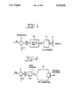
- FIG. 1 shows an embodiment, preferably to be used, of the invention
- FIG. 2 shows a further beneficial embodiment of the invention.
- the literature discloses a solution for rendering an amplifier, for example an optical semiconductor amplifier, less polarization-dependent, use being made of the principle that the signal is amplified twice, i.e. once in the forward direction and for a second time, in the reverse direction. Prior to the amplification in the reverse direction, the polarization of the once amplified signal is rotated. Because the input signal is amplified twice with different polarization directions, the total amplification will be less dependent on the polarization direction of the input signal. To achieve said effect, an orthogonal polarization reflector is used, the polarization of the input signal being orthogonally reflected after amplification by the optical amplifier. An embodiment of this comprises a Faraday rotator and a mirror.
- the invention is based on the inventive insight that it is not necessary for every polarization direction to be reflected orthogonally. Such a reflection will be necessary solely for the horizontal and vertical direction of polarization, assuming that the amplifier has a horizontal principal axis of polarization. Proceeding from this, use can be made of a reflector which is reciprocal, a signal fed thereto and having a vertical polarization being reflected as a reflection signal having a virtually horizontal polarization and vice versa.
- FIG. 1 shows an embodiment, preferably to be used, of the invention.
- Said embodiment comprises a circulator having at least three ports, the input signal is being fed to one port and being emitted at the adjacent port.
- Said adjacent port is connected to an optical amplifier, such as, for example, an optical semiconductor amplifier.
- an optical amplifier such as, for example, an optical semiconductor amplifier.
- a retarder R Provided at the other side of the optical amplifier is a retarder R, in particular a ⁇ /4 retarder, behind which a mirror S is situated.
- the angle between one of the principal axes of the retarder R and the polarization direction of the amplifier is preferably 45°.
- a retarder is a reciprocal device.
- the signal fed thereto can be represented by two components whose polarization directions are mutually perpendicular.
- the retarder delays one component with respect to the other.
- the amplification device input signal is fed to a port of the circulator C and reaches, via an adjacent port thereof, the optical amplifier OA.
- the amplified input signal reaches the ⁇ /4 retarder R with the above-mentioned delay property of the components of the amplified input signal.
- the signal After being reflected by the mirror S, the signal again passes through the retarder R and the optical amplifier OA in the reverse direction.
- the amplified reflection signal rs appears and is separated from the input signal is by means of the circulator C.
- the amplified reflection signal can be taken off as amplifier output signal os at a third port.
- the polarization-reciprocal reflector which in this embodiment consists of the ⁇ /4 retarder R and a mirror S, achieves the result that the output signal os is less polarization-dependent.
- the angle between one of the principal axes of the ⁇ /4 retarder and the polarization of the amplifier is equal to 45°, an optimum polarization independence of the amplification is obtained.
- the simplest form of the retarder is a 45° ⁇ /4 plate. Said plate can be very thin and can consequently be coupled directly to the components interacting therewith, i.e. the amplifier and the mirror. In other words, lenses can be omitted. It is clear that a compact unit is achieved in the case of this embodiment.
- the ⁇ /4 plate converts vertically linearly polarized light into circularly polarized light which is then reflected by the mirror circularly polarized in another direction of orientation (left-hand/right-hand).
- the ⁇ /4 plate then converts the optical signal fed to it into horizontally polarized light. The converse takes place for a horizontally polarized optical input signal.
- the input signal is amplified with a polarization-independent amplification factor by means of the simple configuration described above, which consists solely of reciprocal components.
- the ⁇ /4 retarder can be formed with the same beneficial effect by a section of birefringent glass fiber whose length is equal to 1/2n+1/4 times the beat length, n being equal to 0 or an integer.
- beat length is used in the case of two propagating modes having a different propagation constant.
- the phase difference between the two modes has become 360°.
- beat length instead of “beat length”
- coupling length is also used.
- the two respective modes are the two perpendicular principal polarizations.
- the ⁇ /4 retarder is integrated in the amplifier.
- An optimum compact configuration is obtained if the mirror is formed by a coating layer having a high reflection and provided on the output face of the ⁇ /4 retarder.
- FIG. 2 shows another embodiment of the invention in which the polarization-reciprocal reflector is constructed as a loop reflector having a reciprocal polarization rotation of 90°.
- the input signal After passing through the circulator C, the input signal is fed to a coupling device, for example a 3 dB coupling device, after which the signal emerging from one output port is fed to the amplifier OA.
- the signal originating from the amplifier OA is presented via the coupling device K to one side of a glass fibre loop OF, the other side of said glass fiber being connected to the other output port of the coupling device K.
- Incorporated in the glass fiber loop OF is a 90° circular retarder CR. Said circular retarder may be implemented as a twisted glass fiber section.
- the circular retardation used in this case is also referred to as optical activity.
- a 3 dB coupling device can furthermore be used as take-off device, for which a circulator C is chosen in the embodiment shown.
- the input signal is again amplified with polarization-independent amplification factor.
Abstract
Description
Claims (15)
Applications Claiming Priority (2)
| Application Number | Priority Date | Filing Date | Title |
|---|---|---|---|
| NL9101244A NL9101244A (en) | 1991-07-15 | 1991-07-15 | POLARIZATION-SENSITIVE GAINING DEVICE. |
| NL9101244 | 1991-07-15 |
Publications (1)
| Publication Number | Publication Date |
|---|---|
| US5295016A true US5295016A (en) | 1994-03-15 |
Family
ID=19859521
Family Applications (1)
| Application Number | Title | Priority Date | Filing Date |
|---|---|---|---|
| US07/891,640 Expired - Fee Related US5295016A (en) | 1991-07-15 | 1992-05-29 | Polarization insensitive amplification device |
Country Status (10)
| Country | Link |
|---|---|
| US (1) | US5295016A (en) |
| EP (1) | EP0523766B1 (en) |
| JP (1) | JPH07114299B2 (en) |
| AT (1) | ATE140832T1 (en) |
| CA (1) | CA2070194C (en) |
| DE (1) | DE69212402T2 (en) |
| ES (1) | ES2090483T3 (en) |
| FI (1) | FI922823A (en) |
| NL (1) | NL9101244A (en) |
| NO (1) | NO303897B1 (en) |
Cited By (31)
| Publication number | Priority date | Publication date | Assignee | Title |
|---|---|---|---|---|
| US5822113A (en) * | 1995-02-24 | 1998-10-13 | Lucent Technologies Inc. | Optical amplifier using optical circulator and fiber amplifier |
| US6175446B1 (en) | 1998-09-23 | 2001-01-16 | Sarnoff Corporation | Polarization-independent semiconductor optical amplifier |
| EP1128503A2 (en) * | 2000-02-28 | 2001-08-29 | Nortel Networks Limited | Optical amplifier stage |
| DE10009380A1 (en) * | 2000-02-29 | 2001-09-13 | Schneider Laser Technologies | Fiber amplifier |
| US6335820B1 (en) | 1999-12-23 | 2002-01-01 | Xtera Communications, Inc. | Multi-stage optical amplifier and broadband communication system |
| US6356384B1 (en) | 1998-03-24 | 2002-03-12 | Xtera Communications Inc. | Broadband amplifier and communication system |
| US6359725B1 (en) | 1998-06-16 | 2002-03-19 | Xtera Communications, Inc. | Multi-stage optical amplifier and broadband communication system |
| US6370164B1 (en) | 1996-12-23 | 2002-04-09 | Xtera Communications, Inc. | Broadband sagnac raman amplifiers and cascade lasers |
| US6374006B1 (en) | 1998-03-20 | 2002-04-16 | Xtera Communications, Inc. | Chirped period gratings for raman amplification in circulator loop cavities |
| US6384966B1 (en) * | 1999-11-03 | 2002-05-07 | Time-Bandwidth Products Ag | Multiple pass optical amplifier with thermal birefringence compensation |
| US20020141694A1 (en) * | 2001-03-15 | 2002-10-03 | Massachusetts Institute Of Technology | Methods of achieving optimal communications performance |
| US6567430B1 (en) | 1998-09-21 | 2003-05-20 | Xtera Communications, Inc. | Raman oscillator including an intracavity filter and amplifiers utilizing same |
| US6574037B2 (en) | 1998-06-16 | 2003-06-03 | Xtera Communications, Inc. | All band amplifier |
| US6600592B2 (en) | 1998-03-24 | 2003-07-29 | Xtera Communications, Inc. | S+ band nonlinear polarization amplifiers |
| US6631025B2 (en) | 2000-01-12 | 2003-10-07 | Xtera Communications, Inc. | Low-noise distributed Raman amplifier using bi-directional pumping using multiple Raman orders |
| US6693737B2 (en) | 1998-03-24 | 2004-02-17 | Xtera Communications, Inc. | Dispersion compensating nonlinear polarization amplifiers |
| US6700697B2 (en) * | 2002-01-23 | 2004-03-02 | Np Photonics, Inc. | Reflective erbium-doped amplifier |
| US20040101313A1 (en) * | 2002-11-21 | 2004-05-27 | Fujitsu Limited | Optical repeater |
| US6760148B2 (en) | 1998-03-24 | 2004-07-06 | Xtera Communications, Inc. | Nonlinear polarization amplifiers in nonzero dispersion shifted fiber |
| US6760509B2 (en) | 2000-02-14 | 2004-07-06 | The Regents Of The University Of Michigan | SNR booster for WDM systems |
| US6831779B2 (en) * | 2001-04-27 | 2004-12-14 | Massachusetts Institute Of Technology | Method and apparatus for stabilizing a high-gain, high-power single polarization EDFA |
| US20050078359A1 (en) * | 2003-10-13 | 2005-04-14 | Seung-Woo Kim | Broad-band light source using a semiconductor optical amplifier |
| US6885498B2 (en) | 1998-06-16 | 2005-04-26 | Xtera Communications, Inc. | Multi-stage optical amplifier and broadband communication system |
| US20050088724A1 (en) * | 2003-10-27 | 2005-04-28 | Lee Jeong-Seok | Optical signal transmission apparatus including reflective gain-clamped semiconductor optical amplifier |
| US20050207009A1 (en) * | 2004-03-22 | 2005-09-22 | Efimov Oleg M | Nonreciprocal optical element with independent control of transmission opposite directions |
| US6985283B1 (en) | 1998-06-16 | 2006-01-10 | Xtera Communications, Inc. | Fiber-optic compensation for dispersion, gain tilt, and band pump nonlinearity |
| CN1318870C (en) * | 2004-02-04 | 2007-05-30 | 株式会社Kt | Optical communication system and method thereof |
| WO2007082202A2 (en) * | 2006-01-09 | 2007-07-19 | Chemimage Corporation | Birefringent spectral filter with wide field of view and associated communications method and apparatus |
| US20100296161A1 (en) * | 2007-12-21 | 2010-11-25 | Little Brent E | Polarization insensitive optical circuit |
| US20100302637A1 (en) * | 2007-12-21 | 2010-12-02 | Little Brent E | Polarization insensitive optical circuit |
| US20200403383A1 (en) * | 2019-06-19 | 2020-12-24 | Nec Laboratories America, Inc | Semiconductor amplifier with low polariation-dependent gain |
Families Citing this family (3)
| Publication number | Priority date | Publication date | Assignee | Title |
|---|---|---|---|---|
| US5481391A (en) * | 1994-02-17 | 1996-01-02 | At&T Corp. | Optical fiber system and method for overcoming the effects of polarization gain anisotropy in a fiber amplifier |
| GB2386777A (en) * | 2002-03-19 | 2003-09-24 | Bookham Technology Plc | Polarisation insensitive optical amplifier |
| FR2992482A1 (en) | 2012-06-22 | 2013-12-27 | France Telecom | REFLECTIVE LIGHT DEVICE FOR A WDM PON OPTICAL ACCESS NETWORK COMPRISING A LIGHT SOURCE WITH AN OPTICAL GAIN MEDIUM |
Citations (8)
| Publication number | Priority date | Publication date | Assignee | Title |
|---|---|---|---|---|
| JPH02933A (en) * | 1988-03-25 | 1990-01-05 | Fujitsu Ltd | Optical amplifier |
| US4900917A (en) * | 1988-07-15 | 1990-02-13 | American Telephone And Telegraph Company, At&T Bell Laboratories | Polarization insensitive optical communication device utilizing optical preamplification |
| JPH0293623A (en) * | 1988-09-30 | 1990-04-04 | Nec Corp | Reflection type optical amplifier |
| JPH0298185A (en) * | 1988-10-05 | 1990-04-10 | Nippon Telegr & Teleph Corp <Ntt> | Optical amplifying device |
| US4941738A (en) * | 1988-07-29 | 1990-07-17 | American Telephone And Telegraph Company | Polarization independent optical amplifier apparatus |
| US4952017A (en) * | 1989-03-14 | 1990-08-28 | At&T Bell Laboratories | Polarization independent semiconductor optical amplifier |
| EP0405406A2 (en) * | 1989-06-26 | 1991-01-02 | Oki Electric Industry Co., Ltd. | Optical amplifier |
| US5010586A (en) * | 1987-04-15 | 1991-04-23 | British Telecommunications Public Limited Company | Optical two-way transmission system with loop reflector modulator |
Family Cites Families (1)
| Publication number | Priority date | Publication date | Assignee | Title |
|---|---|---|---|---|
| JPS5740671A (en) * | 1980-08-22 | 1982-03-06 | Seiko Instr & Electronics Ltd | Electronic watch |
-
1991
- 1991-07-15 NL NL9101244A patent/NL9101244A/en not_active Application Discontinuation
-
1992
- 1992-05-29 US US07/891,640 patent/US5295016A/en not_active Expired - Fee Related
- 1992-06-02 CA CA002070194A patent/CA2070194C/en not_active Expired - Fee Related
- 1992-06-04 NO NO922208A patent/NO303897B1/en unknown
- 1992-06-17 FI FI922823A patent/FI922823A/en unknown
- 1992-06-18 EP EP92201796A patent/EP0523766B1/en not_active Expired - Lifetime
- 1992-06-18 DE DE69212402T patent/DE69212402T2/en not_active Expired - Fee Related
- 1992-06-18 AT AT92201796T patent/ATE140832T1/en not_active IP Right Cessation
- 1992-06-18 ES ES92201796T patent/ES2090483T3/en not_active Expired - Lifetime
- 1992-07-08 JP JP4218117A patent/JPH07114299B2/en not_active Expired - Fee Related
Patent Citations (8)
| Publication number | Priority date | Publication date | Assignee | Title |
|---|---|---|---|---|
| US5010586A (en) * | 1987-04-15 | 1991-04-23 | British Telecommunications Public Limited Company | Optical two-way transmission system with loop reflector modulator |
| JPH02933A (en) * | 1988-03-25 | 1990-01-05 | Fujitsu Ltd | Optical amplifier |
| US4900917A (en) * | 1988-07-15 | 1990-02-13 | American Telephone And Telegraph Company, At&T Bell Laboratories | Polarization insensitive optical communication device utilizing optical preamplification |
| US4941738A (en) * | 1988-07-29 | 1990-07-17 | American Telephone And Telegraph Company | Polarization independent optical amplifier apparatus |
| JPH0293623A (en) * | 1988-09-30 | 1990-04-04 | Nec Corp | Reflection type optical amplifier |
| JPH0298185A (en) * | 1988-10-05 | 1990-04-10 | Nippon Telegr & Teleph Corp <Ntt> | Optical amplifying device |
| US4952017A (en) * | 1989-03-14 | 1990-08-28 | At&T Bell Laboratories | Polarization independent semiconductor optical amplifier |
| EP0405406A2 (en) * | 1989-06-26 | 1991-01-02 | Oki Electric Industry Co., Ltd. | Optical amplifier |
Non-Patent Citations (2)
| Title |
|---|
| Electronics Letters, No. 22, Oct. 25, 1990, Stevenage GB Herts., GB, 1913 1914, M. Sumida, Polarisation Insensitive Configuration of Semiconductor Laser Amplifier . * |
| Electronics Letters, No. 22, Oct. 25, 1990, Stevenage GB Herts., GB, 1913-1914, M. Sumida, "Polarisation Insensitive Configuration of Semiconductor Laser Amplifier". |
Cited By (53)
| Publication number | Priority date | Publication date | Assignee | Title |
|---|---|---|---|---|
| US5822113A (en) * | 1995-02-24 | 1998-10-13 | Lucent Technologies Inc. | Optical amplifier using optical circulator and fiber amplifier |
| US6370164B1 (en) | 1996-12-23 | 2002-04-09 | Xtera Communications, Inc. | Broadband sagnac raman amplifiers and cascade lasers |
| US20030058899A1 (en) * | 1996-12-23 | 2003-03-27 | Xtera Communications, Inc., A Delaware Corporation | Optical amplification using polarization diversity pumping |
| US6833946B2 (en) | 1996-12-23 | 2004-12-21 | Xtera Communications, Inc. | Optical amplification using polarization diversity pumping |
| US6374006B1 (en) | 1998-03-20 | 2002-04-16 | Xtera Communications, Inc. | Chirped period gratings for raman amplification in circulator loop cavities |
| US6356384B1 (en) | 1998-03-24 | 2002-03-12 | Xtera Communications Inc. | Broadband amplifier and communication system |
| US6600592B2 (en) | 1998-03-24 | 2003-07-29 | Xtera Communications, Inc. | S+ band nonlinear polarization amplifiers |
| US6693737B2 (en) | 1998-03-24 | 2004-02-17 | Xtera Communications, Inc. | Dispersion compensating nonlinear polarization amplifiers |
| US6693738B2 (en) | 1998-03-24 | 2004-02-17 | The Regents Of The University Of Michigan | Broadband amplifier and communication system |
| US6760148B2 (en) | 1998-03-24 | 2004-07-06 | Xtera Communications, Inc. | Nonlinear polarization amplifiers in nonzero dispersion shifted fiber |
| US6580548B2 (en) | 1998-03-24 | 2003-06-17 | Xtera Communications, Inc. | Broadband amplifier and communication system |
| US6885498B2 (en) | 1998-06-16 | 2005-04-26 | Xtera Communications, Inc. | Multi-stage optical amplifier and broadband communication system |
| US6985283B1 (en) | 1998-06-16 | 2006-01-10 | Xtera Communications, Inc. | Fiber-optic compensation for dispersion, gain tilt, and band pump nonlinearity |
| US6359725B1 (en) | 1998-06-16 | 2002-03-19 | Xtera Communications, Inc. | Multi-stage optical amplifier and broadband communication system |
| US6574037B2 (en) | 1998-06-16 | 2003-06-03 | Xtera Communications, Inc. | All band amplifier |
| US6567430B1 (en) | 1998-09-21 | 2003-05-20 | Xtera Communications, Inc. | Raman oscillator including an intracavity filter and amplifiers utilizing same |
| US6175446B1 (en) | 1998-09-23 | 2001-01-16 | Sarnoff Corporation | Polarization-independent semiconductor optical amplifier |
| US6384966B1 (en) * | 1999-11-03 | 2002-05-07 | Time-Bandwidth Products Ag | Multiple pass optical amplifier with thermal birefringence compensation |
| US6335820B1 (en) | 1999-12-23 | 2002-01-01 | Xtera Communications, Inc. | Multi-stage optical amplifier and broadband communication system |
| US6631025B2 (en) | 2000-01-12 | 2003-10-07 | Xtera Communications, Inc. | Low-noise distributed Raman amplifier using bi-directional pumping using multiple Raman orders |
| US6714342B2 (en) | 2000-01-12 | 2004-03-30 | Xtera Communications, Inc. | Low-noise distributed Raman amplifier using bi-directional pumping using multiple Raman orders |
| US6760509B2 (en) | 2000-02-14 | 2004-07-06 | The Regents Of The University Of Michigan | SNR booster for WDM systems |
| EP1128503A3 (en) * | 2000-02-28 | 2003-08-06 | Nortel Networks Limited | Optical amplifier stage |
| EP1128503A2 (en) * | 2000-02-28 | 2001-08-29 | Nortel Networks Limited | Optical amplifier stage |
| US20020101650A1 (en) * | 2000-02-28 | 2002-08-01 | King Jonathan P. | Optical amplifier stage |
| DE10009380A1 (en) * | 2000-02-29 | 2001-09-13 | Schneider Laser Technologies | Fiber amplifier |
| DE10009380B4 (en) * | 2000-02-29 | 2007-11-08 | Jenoptik Ldt Gmbh | fiber amplifier |
| US6919986B2 (en) | 2000-05-05 | 2005-07-19 | Xtera Communications, Inc. | Nonlinear polarization amplifiers in nonzero dispersion shifted fiber |
| US20020141694A1 (en) * | 2001-03-15 | 2002-10-03 | Massachusetts Institute Of Technology | Methods of achieving optimal communications performance |
| US8958666B2 (en) | 2001-03-15 | 2015-02-17 | Massachusetts Institute Of Technology | Methods of achieving optimal communications performance |
| US20080019705A1 (en) * | 2001-03-15 | 2008-01-24 | Caplan David O | Methods of achieving optimal communications performance |
| US7181097B2 (en) | 2001-03-15 | 2007-02-20 | Massachusetts Institute Of Technology | Methods of achieving optimal communications performance |
| US6831779B2 (en) * | 2001-04-27 | 2004-12-14 | Massachusetts Institute Of Technology | Method and apparatus for stabilizing a high-gain, high-power single polarization EDFA |
| US6700697B2 (en) * | 2002-01-23 | 2004-03-02 | Np Photonics, Inc. | Reflective erbium-doped amplifier |
| US7616377B2 (en) | 2002-11-21 | 2009-11-10 | Fujitsu Limited | Optical repeater |
| US7375878B2 (en) * | 2002-11-21 | 2008-05-20 | Fujitsu Limited | Optical repeater |
| US20040101313A1 (en) * | 2002-11-21 | 2004-05-27 | Fujitsu Limited | Optical repeater |
| US7173757B2 (en) * | 2003-10-13 | 2007-02-06 | Samsung Electronics Co., Ltd. | Broad-band light source using a semiconductor optical amplifier |
| US20050078359A1 (en) * | 2003-10-13 | 2005-04-14 | Seung-Woo Kim | Broad-band light source using a semiconductor optical amplifier |
| US20050088724A1 (en) * | 2003-10-27 | 2005-04-28 | Lee Jeong-Seok | Optical signal transmission apparatus including reflective gain-clamped semiconductor optical amplifier |
| US7110168B2 (en) * | 2003-10-27 | 2006-09-19 | Samsung Electronics Co., Ltd. | Optical signal transmission apparatus including reflective gain-clamped semiconductor optical amplifier |
| CN1318870C (en) * | 2004-02-04 | 2007-05-30 | 株式会社Kt | Optical communication system and method thereof |
| US6965472B2 (en) * | 2004-03-22 | 2005-11-15 | Raytheon Company | Nonreciprocal optical element with independent control of transmission opposite directions |
| US20050207009A1 (en) * | 2004-03-22 | 2005-09-22 | Efimov Oleg M | Nonreciprocal optical element with independent control of transmission opposite directions |
| WO2007082202A3 (en) * | 2006-01-09 | 2008-07-24 | Chemimage Corp | Birefringent spectral filter with wide field of view and associated communications method and apparatus |
| US7848000B2 (en) | 2006-01-09 | 2010-12-07 | Chemimage Corporation | Birefringent spectral filter with wide field of view and associated communications method and apparatus |
| WO2007082202A2 (en) * | 2006-01-09 | 2007-07-19 | Chemimage Corporation | Birefringent spectral filter with wide field of view and associated communications method and apparatus |
| US20100296161A1 (en) * | 2007-12-21 | 2010-11-25 | Little Brent E | Polarization insensitive optical circuit |
| US20100302637A1 (en) * | 2007-12-21 | 2010-12-02 | Little Brent E | Polarization insensitive optical circuit |
| US8314988B2 (en) | 2007-12-21 | 2012-11-20 | Infinera Corporation | Polarization insensitive optical circuit |
| US8452185B2 (en) * | 2007-12-21 | 2013-05-28 | Infinera Corporation | Polarization insensitive optical circuit |
| US20200403383A1 (en) * | 2019-06-19 | 2020-12-24 | Nec Laboratories America, Inc | Semiconductor amplifier with low polariation-dependent gain |
| WO2020257473A1 (en) * | 2019-06-19 | 2020-12-24 | Nec Laboratories America, Inc. | Semiconductor amplifier with low polarization-dependent gain |
Also Published As
| Publication number | Publication date |
|---|---|
| NO922208D0 (en) | 1992-06-04 |
| DE69212402T2 (en) | 1997-01-23 |
| DE69212402D1 (en) | 1996-08-29 |
| EP0523766A1 (en) | 1993-01-20 |
| NL9101244A (en) | 1993-02-01 |
| JPH05211368A (en) | 1993-08-20 |
| FI922823A0 (en) | 1992-06-17 |
| JPH07114299B2 (en) | 1995-12-06 |
| ES2090483T3 (en) | 1996-10-16 |
| NO922208L (en) | 1993-01-18 |
| FI922823A (en) | 1993-01-16 |
| CA2070194A1 (en) | 1993-01-16 |
| ATE140832T1 (en) | 1996-08-15 |
| EP0523766B1 (en) | 1996-07-24 |
| NO303897B1 (en) | 1998-09-14 |
| CA2070194C (en) | 1997-04-01 |
Similar Documents
| Publication | Publication Date | Title |
|---|---|---|
| US5295016A (en) | Polarization insensitive amplification device | |
| US6014256A (en) | Polarizing beam splitter/combiner | |
| US6498680B1 (en) | Compact tunable optical wavelength interleaver | |
| CA2078994A1 (en) | Optical apparatus | |
| JPH09189885A (en) | Optical device | |
| US5936768A (en) | Optical passive device for an optical fiber amplifier and the optical amplifier | |
| US5726801A (en) | Reduced optical isolator module for a miniaturized laser diode assembly | |
| JPH10170867A (en) | Optical device with optical circulator function | |
| JPH07281128A (en) | Optical isolator | |
| US6885821B2 (en) | Full-duplex optical add/drop communications system utilizing central light sources | |
| US6954307B2 (en) | Four-port PM circulator | |
| US5734667A (en) | Polarization-stable laser | |
| CN208984906U (en) | A kind of integrated free space optical circulator | |
| JP2761141B2 (en) | Polarization rotating mirror | |
| JPH0527200A (en) | Polarized wave coupler | |
| JPH0246432A (en) | Optical amplifier | |
| CN211859134U (en) | Light path multiplexing double-stage optical isolator | |
| CN217543553U (en) | Polarization beam splitter | |
| CN115963602A (en) | Polarization-maintaining optical fiber circulator | |
| JP2977926B2 (en) | Optical circulator | |
| EP0283227A2 (en) | Optical isolator | |
| JP2744295B2 (en) | Polarization coupler | |
| JPS62200319A (en) | Optical fiber circuit device | |
| JP2612912B2 (en) | Optical amplifier | |
| AU675424B2 (en) | Improvements to optical phase shifting |
Legal Events
| Date | Code | Title | Description |
|---|---|---|---|
| AS | Assignment |
Owner name: KONINKLIJKE PTT NEDERLAND N.V., A CORP. OF THE NET Free format text: ASSIGNMENT OF ASSIGNORS INTEREST.;ASSIGNOR:VAN DEVENTER, MATTIJS O.;REEL/FRAME:006160/0262 Effective date: 19920429 |
|
| FEPP | Fee payment procedure |
Free format text: PAYOR NUMBER ASSIGNED (ORIGINAL EVENT CODE: ASPN); ENTITY STATUS OF PATENT OWNER: LARGE ENTITY |
|
| FPAY | Fee payment |
Year of fee payment: 4 |
|
| AS | Assignment |
Owner name: KONINKLIJKE KPN N.V., NETHERLANDS Free format text: CHANGE OF NAME;ASSIGNOR:KONINKLIJKE PTT NEDERLAND N.V.;REEL/FRAME:009624/0331 Effective date: 19980628 |
|
| AS | Assignment |
Owner name: KONINKLIJKE KPN N.V., NETHERLANDS Free format text: CHANGE OF CORPORATE ADDRESS EFFECTIVE 08-27-99;ASSIGNOR:KONINKLIJKE KPN N.V.;REEL/FRAME:010710/0764 Effective date: 19990827 |
|
| FPAY | Fee payment |
Year of fee payment: 8 |
|
| REMI | Maintenance fee reminder mailed | ||
| LAPS | Lapse for failure to pay maintenance fees | ||
| STCH | Information on status: patent discontinuation |
Free format text: PATENT EXPIRED DUE TO NONPAYMENT OF MAINTENANCE FEES UNDER 37 CFR 1.362 |
|
| FP | Lapsed due to failure to pay maintenance fee |
Effective date: 20060315 |