TECHNICAL FIELD
The present invention relates to a device and a method for controlling a construction vehicle mainly for loading work such as a wheel loader, etc.
BACKGROUND OF THE INVENTION
A conventional control system of a device for controlling a wheel loader mainly for loading work is illustrated in FIG. 11.
With reference to FIG. 11, the output of an engine E is transmitted to a torque converter TC and a gear G and the output transmitted to the gear G drives hydraulic pumps P1 and P2 of a fixed capacity.
A bucket operation pilot valve AL is operated to actuate a bucket main operation valve AV to thereby turn a bucket A by way of a bucket cylinder AC, so that the bucket A tilts rearward or dumps forward.
A boom operation pilot valve BL is operated to actuate a boom main operation valve BV to thereby turn a boom B by way of a boom cylinder BC, so that the boom B lifts upward or lowers downward.
Designated at PP is a pilot pump.
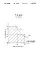
The performance of the hydraulic pumps P1 and P2 of a fixed capacity in the conventional control system of a working machine is illustrated in FIG. 12(a).
In the same figure, P1, P2, Q1 and Q2 represent respectively the oil pressures and the flow rates of the hydraulic pumps P1 and P2.
A rectangle surrounded by O-P2 -P2 Q2 point-Q2 is a region where the hydraulic pump P2 alone operates and a hatching portion surrounded by O-P2 -P2 Q2 point-P1 Q2 point-P1 Q1 point-Q1 is a region where both the hydraulic pumps P1 and P2 operate.
FIG. 12(b) is a graph showing a torque curve of the output of an engine wherein TEM is a torque curve at the full throttling time, TEM G is a torque curve when an electronic control type governor operates, TT is an absorption torque curve of a torque converter, NC1 is an engine speed at the point where the absorption torque curve TT intersects the torque curve TEM G, TPA is an average hydraulic pump torque when the oil pressure in a hydraulic circuit of a working machine is low, TA1 is a torque at the point where the absorption torque curve TT intersects the curve of the torque obtained by subtracting TPA from TEM, TB1 is a torque at the point where the absorption torque curve TT intersects the curve of the torque obtained by subtracting TPB from TEM, and NB1 is an engine speed at that time.
Referring back to FIG. 12(a), designated at PA is a pressure at the point where the average hydraulic pump torque curve TPA at a low oil pressure intersects the vertical line connecting the P1 Q1 point to Q1 and PB is an oil pressure at the point where the average oil pressure pump torque curve TPB at a high oil pressure intersects the vertical line connecting the P2 Q2 point to Q2.
As is evident from FIGS. 12(a) and (b), according to the conventional control system of the working machine, the distribution of the output of the engine to the travel of the vehicle and the operation of the working machine are selected in two steps depending on the oil pressure, namely, a high pressure or a low pressure in the hydraulic circuit of the working machine.
That is, the hydraulic pump torque TPB, i.e. an oil pressure load TPB is reduced at the high pressure (e.g. at the excavating time) so that the torque curve TEM, i.e. the output TEM of the engine is much distributed to the travel torque TB1 and the hydraulic pump torque TPA, i.e. an oil pressure load TPA is increased at the low pressure (e.g. at the load lifting time) so that the output TEM of the engine is much distributed to the operation of the working machine, whereby the output of the engine can be effectively utilized.
In the conventional control system, since the engine torque TEM is fixed, the distribution of the torque at the travelling time and the working time is limited by the pump capacity (Q1 or Q1 +Q2) so that the output of the engine for the travel is difficult to be ideally set (actually an operator performs the throttle operation to thereby control the travel output).
There is such a serious problem in the conventional control system for selecting the pump capacity in two steps by the oil pressure alone that the variation of the output of the working machine, particularly the variation of the speed of the working machine occurs in the middle of working so that an unskilled operator can hardly operate the working machine.
There is another problem that the engine speed hardly increases when it is changed from a low speed to a speed burst and a heavy load working is required adding to that.
It is an object of the present invention to solve the problems set forth above.
SUMMARY OF THE INVENTION
To achieve the above object, the present invention provides a device for controlling a loading work vehicle equipped with a plurality of hydraulic pumps of a fixed capacity for a loading work machine and with a torque converter, the device comprising an engine equipped with an electronic control type governor or an electric governor as a means for controlling the output of the engine, changeover valves for changing over the flow of pressure oil to a drain circuit in response to the oil pressure of the working machine or an electric instruction are disposed in the circuit on the downstream side of one of the hydraulic pumps for the working machine, a selection switch for selecting output characteristics, a governor controller for controlling engine output characteristic selected by said switch, and a cut-off valve controller for actuating the changeover valves in response to the electric instruction of the selection switch.
Furthermore, the device is equipped with means for detecting stepping amount of an accelerator pedal and an engine speed detector, both of which give instruction signals to the governor controller, and a selection switch for changing over from a forward second speed to a forward first speed wherein the governor controller decides a full throttled state at a low engine speed and the changeover from the forward second speed to the forward first speed, thereby issuing a switchover valve signal to the switchover valve to reduce an oil pressure load of the engine. Still furthermore, a maximum engine speed of the engine equipped with the electric governor controller is varied in response to an output signal of a working oil pressure detector of the working machine.
BRIEF DESCRIPTION OF THE DRAWINGS
FIG. 1 is a view showing the control system of a vehicle for loading work according to a first embodiment of the present invention,
FIG. 2(a) is a graph showing pump torque characteristic curves at an M2 mode,
FIG. 2(b) is a graph showing power distribution characteristic curves at the M2 mode,
FIG. 3 is a flow chart showing an operating procedure,
FIG. 4(a) is a graph showing pump torque characteristic curves at an M3 mode of FIG. 4(b) is a graph showing a power distribution characteristic curve at the M3 mode.
FIG. 5 is a control system diagram according to a second embodiment of the present invention and
FIGS. 6(a) and (b),
FIGS. 7(a) and (b), and
FIGS. 8(a) and (b) are graphs showing pump torque characteristic curves and power distribution characteristic curves at an M1 mode, the M2 mode and the M3 mode.
FIG. 9 is a flow chart showing an operating procedure according to the second embodiment of the present invention,
FIG. 10 is a view showing a method of controlling the cut-off valve by the engine speed and the stepping amount of the accelerator pedal,
FIG. 11 shows a conventional control system diagram and
FIGS. 12(a) and (b) are graphs showing pump torque characteristic curves and power distribution characteristic curves at the M1 mode according to the first embodiment of the present invention (and the conventional one in FIG. 11).
DETAILED DESCRIPTION
An embodiment of the present invention will be described with reference to drawings.
FIG. 1 is a view showing the control system of a vehicle for loading work according to the first embodiment of present invention wherein elements which operate in the same way as the conventional system as explained in FIG. 11 are denoted at the same numerals.
An engine E has an electronic control type governor 10 which is mounted thereon and is capable of optionally selecting output characteristics in steps and an electronic governor controller 11 is provided for controlling the electronic control type governor 10 in response to input signals (1) to (4) set forth hereunder.
(1) a signal representing an engine speed NE issued by a rotary sensor 12 provided on the gear G
(2) a cut-off valve operation signal issued by a cut-off valve controller 13 (the electronic governor controller 11 receives the cut-off valve signal as the input signal and issues information signals)
(3) a stepping amount signal σA issued by an accelerator pedal 14
(4) mode signals issued by a mode selection switch 15
The cut-off valve controller 13 receives signals from and sends signals to the electronic governor controller 11 and receives signals issued by an F2 (forward second speed)-F1(forward first speed) selection switch 19 provided at a boom operation pilot valve BL (TMC is a transmission controller) and outputs a signal to a changeover valve, i.e. an electromagnetic pilot cut-off valve 18 to thereby select the electromagnetic pilot cut-off valve 18. A changeover valve, i.e. a pilot unload valve 17, which is selectively switched by the oil pressure of the hydraulic pump P2, is provided at the discharge side of the hydraulic pump P2. Since the pilot unload valve 17 and the electromagnetic pilot cut-off valve 18 are respectively coupled to the pilot oil pressure side of a main unload valve 16, the unload oil pressure of the hydraulic pump P1 is determined by the oil pressure of the hydraulic pump P2 and the cut-off valve controller 13.
An operation of the embodiment will be described hereinafter.
If the mode 1 is selected by operating the selection switch 15, the M1 mode is obtained in the same way as the conventional method which is explained in FIGS. 12(a) and (b).
If the mode 2 is selected, the electromagnetic cut-off valve 18 is positioned at a cut-off position at the excavating time alone so that the M2 mode is obtained as illustrated in FIGS. 2(a) and (b).
That is, in FIGS. 2(a) and (b), those which are denoted at the same numerals as those in FIGS. 12(a) and (b) are same. At the M2 mode, an engine torque as denoted at TEM2 is set under the output TEM of the engine as illustrated in FIG. 2(b).
Since the average oil pressure pump torque TPA and the average oil pressure pump torque TPB are respectively taken from the engine torque TEM2, the available travel engine torque curves intersect the absorption torque curve TT at the points of TA2 and TB2 (each corresponding to the driving power and the travel speed of the vehicle) so that the available travel engine torques are represented by line segments TA2 NA2 and TB2 NB2.
Although high oil pressure is required at the excavating time when the transmission gear ratio is changed from the forward second speed F2 to the forward first speed F1, the hydraulic pump P2 alone is operated since the excavating operation is easily made at the time when the amount of oil is less varied.
The oil pressure versus the flow rate of the hydraulic pump is shown in FIG. 2(a) as the region (denoted at B) surrounded by O-P2 -P2 Q2 point-Q2.
Since the electromagnetic pilot cut-off valve 18 is positioned at the cut-off position, the average oil pressure pump torque TPA ' at the low pressure at this time is under the average oil pressure pump torque TPA as illustrated in FIG. 2(a) and the engine torque corresponding to the driving power and travel speed of the vehicle at this time is represented by line segment TA2 'NA2 ' which is larger than line segment TA2 NA2 as illustrated in FIG. 2(b) so that the performance of the vehicle is improved.
That is, if the M1 mode is compared with the M2 mode, the following expressions are established, wherein the driving power at the M2 mode is set to be equal to or less than that at the M1 mode. ##EQU1##
An operation procedure at the M2 mode is illustrated in the flow chart of FIG. 3 which reads as follows.
(1) (Start)→(2) (M2 mode?)→(3) (F2 to F1 selection switch is ON?)→(4){Cut-off valve output is ON (Pump P1 unload).}
If the selection switch 15 is operated to select the M3 mode, the electromagnetic pilot cut-off valve 18 is always positioned at the cut-off position so that the M3 mode as illustrated in FIGS. 4(a) and (b) is obtained.
That is, since the device is usually operated by the hydraulic pump P2 alone, when the M2 mode is compared with the M3 mode, the following expressions are established wherein the driving power at the M3 mode is equal to or less than that at the M2 mode. ##EQU2##
An operation procedure at the M3 mode is illustrated in the flow chart of FIG. 3 which reads as follows.
(1) (Start)→(2) (M2 mode?)→(5) (M3 mode?)→(4) {Cut-off valve output is ON (Pump P1 unload).
FIG. 5 is a view showing a control system according to a second embodiment of the present invention wherein the difference between the second embodiment and the first embodiment is that the electronic control type governor 10 in FIG. 1 is replaced by an electric governor 23 in FIG. 5 which successively can turn the control lever of the governor and the electronic governor controller 11 in FIG. 1 is replaced by an electric governor controller 21 in FIG. 5 and furthermore the pilot unload valve 17 in FIG. 1 is omitted but a pressure detector (analog) 26 is provided.
Designated at 22 is an injection pump, 23 is the electric governor, 24 is a governor motor and 25 is a governor potentiometer.
Performance curves according to the second embodiment is illustrated in FIGS. 6(a) and (b) (M1 mode), FIGS. 7(a) and (b) (M2 mode) and FIGS. 8(a) and (b) (M3 mode) which are substantially respectively similar to the performance curves according to the first embodiment as illustrated in FIGS. 12(a) and (b) (M1 mode), FIGS. 2(a) and (b) (M2 mode) and FIGS. 4(a) and (b) (M3 mode). Set forth hereunder is only the difference between the performance curves of the first embodiment and those of the second embodiment.
The maximum engine speed which is controlled by the electric governor controller 21 varies in response to the amplitude of the output signal issued by the pressure detector 26 as illustrated in FIG. 7(b) and FIG. 8(b).
That is, the maximum engine speed is restricted by the oil pressure load (the engine torque TEM is fixed) and the reduction ratio ΔN of the maximum engine speed is proportional to the oil pressure P and is set to meet the following expression so as to set the optimum driving power against the oil pressure load. That is, at the M2 mode, in case that the forward second speed F2 is changed to the forward first speed F1, the expression of ΔN2 '/N2 ≈PA /PB is established while in other cases, the expression of ΔN2 "/ΔN2 '=K (proportional constant) is established and at the M3 mode, the expression of ΔN3 '/N3 ≈PA /PB is established.
A control flow chart at this time is illustrated in FIG. 9.
Described hereinafter are a method of and an operation of controlling the cut-off valve by the engine speed and the stepping amount of the accelerator pedal.
The control method is common to the first embodiment as illustrated in FIG. 1 and the second embodiment as illustrated in FIG. 5 wherein the accelerator pedals are represented respectively as electric pedals 14 and cut-off valves are represented as electromagnetic pilot cut-off valve 18.
According to the control flow chart in FIG. 3, an operation procedure reads as (1) (Start)→(6) {Less than engine speed N1 (a previously set engine speed)?}→(7) (Is accelerator pedal at a full throttle position?)→(4) {Cut-off valve output is ON (Pump P1 is unloaded).} (Also refer to FIG. 10).
Accordingly, for example, when the engine speed is low and an excess torque of the engine is low such as the time when the vehicle accelerates while lifting the load, an oil pressure consumption torque is temporarily reduced to thereby improve the increase of the engine speed.
With the arrangement as set forth above in detail, the present invention has the following great effect.
(1) Since engine output, hydraulic driving power, and driving power can be set in a plurality of degrees by combining the cut-off conditions of the hydraulic pumps in steps in response to the selected engine output, functions of the vehicle can be set according to the work load or work amount.
Since the oil pressure load is electrically selected at the M2 and M3 modes, the working speed in response to the nature of the work can be obtained and even an unskilled operator can operate the device with ease.
Since the engine output, the hydraulic driving power, and the driving power are respectively restricted by the work load at the M2 and M3 modes, the fuel consumption can be reduced.
(2) It is possible to set functions of the vehicle according to the work load since the distribution of the hydraulic driving power and the driving power can be optionally set relative to the output of the engine by permitting the governor lever to turn automatically.
Since the output of the engine is restricted according to the work load, the fuel consumption can be reduced.
Furthermore, since the governor control is automatically made, it is not necessary for the operator to operate frequently the throttle valve (stepping operation).
(3) If there occurs such a need that the engine speed is changed from the low speed to the speed burst and the heavy load is required, e.g. at the time of starting the engine while lifting the load, it is possible to improve the accelerating performance of the engine.
(4) It is possible to work with ease without enlarging variation of the working speed at the excavating time by varying the pump load and operating only one of the hydraulic pumps when the operator operates the F2 (forward second speed)-F1(forward first speed) selection switch 19 to issue the instruction at the excavating time at the M2 mode. Furthermore, it is possible to restrict the oil pressure torque at the excavating time.