US5297780A - Rescue spreading tool - Google Patents
Rescue spreading tool Download PDFInfo
- Publication number
- US5297780A US5297780A US07/952,688 US95268892A US5297780A US 5297780 A US5297780 A US 5297780A US 95268892 A US95268892 A US 95268892A US 5297780 A US5297780 A US 5297780A
- Authority
- US
- United States
- Prior art keywords
- motor
- light weight
- spreading
- rescue device
- sun gear
- Prior art date
- Legal status (The legal status is an assumption and is not a legal conclusion. Google has not performed a legal analysis and makes no representation as to the accuracy of the status listed.)
- Expired - Lifetime
Links
Images


Classifications
-
- A—HUMAN NECESSITIES
- A62—LIFE-SAVING; FIRE-FIGHTING
- A62B—DEVICES, APPARATUS OR METHODS FOR LIFE-SAVING
- A62B3/00—Devices or single parts for facilitating escape from buildings or the like, e.g. protection shields, protection screens; Portable devices for preventing smoke penetrating into distinct parts of buildings
- A62B3/005—Rescue tools with forcing action
-
- Y—GENERAL TAGGING OF NEW TECHNOLOGICAL DEVELOPMENTS; GENERAL TAGGING OF CROSS-SECTIONAL TECHNOLOGIES SPANNING OVER SEVERAL SECTIONS OF THE IPC; TECHNICAL SUBJECTS COVERED BY FORMER USPC CROSS-REFERENCE ART COLLECTIONS [XRACs] AND DIGESTS
- Y10—TECHNICAL SUBJECTS COVERED BY FORMER USPC
- Y10S—TECHNICAL SUBJECTS COVERED BY FORMER USPC CROSS-REFERENCE ART COLLECTIONS [XRACs] AND DIGESTS
- Y10S72/00—Metal deforming
- Y10S72/705—Vehicle body or frame straightener
Definitions
- This invention relates to portable devices which deliver spreading or cutting motion under high loads and particularly those devices used for emergency rescue conditions and commonly referred to as "jaws of life” devices.
- Rescue tools known as "jaws of life” devices are specialized tools used by various rescue personnel such as police, firemen, paramedics generally for the purpose of extricating accident victims from vehicles whose exits have been rendered inoperable. These tools require spreading and closing forces for opening or ripping apart inoperable doors or for cutting through relatively thick metal layers. Pushing and pulling forces of 7,000 to 15,000 pounds at the tips are considered to be normal for the proper operation of such tools. In the past, in order to achieve such high forces, the tools have been almost exclusively hydraulic and powered by gasoline engines, for example as described in U.S. Pat. No. 4,842,249.
- Some tools such as described in U.S. Pat. No. 4,896,862 are designed as separate jaw elements for use with various available powered inputs such as a pneumatic or hydraulic pumps or electric motors which drive threaded actuating elements. Though described as being powered with an electric motor, most devices are powered by gasoline or other fuel operated devices which provide the requisite driving power in a portable fashion. Electric power sources are not readily available in most emergency situations and portable batteries have not been considered capable of providing the requisite torque for effective operation of such devices.
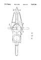
- FIG. 1 is an isometric view of one embodiment of the device of the present invention with an in-line gear driving motor;
- FIG. 2 is an isometric partial cutaway of the planetary gear arrangement in the embodiment of FIG. 1.
- FIGS. 3 and 4 are top and bottom views of a second embodiment of the device of the present invention with a motor parallel to the gearing and with a pulley drive;
- FIG. 5 is a front cutaway view of the device shown in FIGS. 3 and 4 showing the drive and torque increasing gear system;
- FIG. 6 is a side view of the arm attachment pin
- FIG. 7 is a right side view showing the handle attachment in the various embodiments.
- the present invention comprises a truly light weight portable rescue device of the "jaws of life" type having spreading arms which will quietly deliver cutting and/or spreading motions under very high loads and in any arm position.
- the device comprises a portable heavy duty motor, such as a motor utilized in operating portable winches, which is most preferably powered by a DC power supply such as typical 12 volt DC vehicle batteries.
- the output of the motor is converted to a low controllable speed and high torque by input speed reduction means such as a rotary multiple stage gear box having a compound planetary output stage.
- the geared output permits the effective utilization of portable battery powering for use in a "jaws of life” device.
- the gear box comprises a sun gear which is driven by the motor and planetary spindle gears driven by the sun gear.
- the output stage of the planetary spindle gears is connected to one or more of the spreading arms which emanate from a common vertex via ring gears and ring lugs.
- Other speed reduction means include compound gearing, cluster gearing
- the self contained electric motor be of an explosion proof type and that a fail-safe, electrically off, brake be interposed between the motor input and the geared output. Since the device is electrically powered by a vehicle battery there is no ignitable fuel and the tool is relatively safe for most rescue operations. The only maintenance required is periodic gear lubrication and even this can be dispensed with in a closed, self lubricating system.
- Actuators including gear boxes which have arms that extend from rotating ring gears of planetary gear systems and which are useful in the present invention, include those utilized in positioning aircraft flight control surfaces. Such actuators are disclosed in U.S. Pat. Nos. 4,721,016; 4,742,730; 4,825,723; and 5,120,285 as well as U.S. Pat. No. 5,106,354 which discloses a gear system designed for specific use in folding aircraft wings.
- the device is provided with a large handle for stable two hand control and the handle is provided with a power switch for actuating of the arms in either the arms spreading (ripping) or arm closing (cutting or snipping) modes.
- the planetary gears drive ring gears with external ring lugs which are attached to the appropriate arms (high strength spreaders, sharpened cutters and the like) via removable pins. This provides the rapid ability to tailor the rescue tool to the particular situation. Either both arms are moved away from an original position or more preferably for simplified construction, one arm is fixed in position on the housing of the device and the other arm moves relative thereto.
- a particularly desirable configuration for the geared torque increasing means is a compound planetary containing gearbox comprised of floating planet gears which eliminate the conventional carrier and planet support bearings.
- the present invention Since the power supply (a 12 volt DC battery) is available in nearly any vehicle, and separable from the device, the present invention is truly lightweight (typically, with a weight of about thirty pounds as compared to common devices weighing in excess of 200 pounds and which require two people for operation) and substantially more portable than those of the prior art, with effective utilization by one person. Since the device carries no fuel it is also easily transported without the specialized carriers necessary with gasoline powered hydraulic equipment. In addition, the device is nearly as safe as simple mechanically operated tools under inclement conditions.
- FIG. 1 depicts a rescue device 10 of the present invention, which, with spreading arms 12a and 12b having flat opposing surfaces, is specifically designed for ripping open or spreading operations.
- the spreading arms 12a and 12b because of the high stress forces placed on them, are preferably comprised of high strength tool steel (or any other high strength material appropriate for the load) and are apertured to reduce weight.
- the spreading tips of arms 12a and 12b are solid and stepped for appropriate selective placement in correspondingly sized openings, particularly for firm grip on jagged metal and for creating a wedge shaped opening so that difficult jobs can be done in several small spreads rather than one large spread.
- Heavy duty explosion proof motor 13 is powered by a 12 volt DC battery such as a vehicle battery (not shown) via power cable 9.
- the motor 13 directly drives the gearbox shown in FIG. 2.
- Input gears 14 translate rotary movement from motor 13, to turn sun gear 17.
- Centrally positioned sun gear 17 in turn causes rotation of planetary spindle gears 18 to drive ring gears 19, thereby providing the requisite high torque movement of arm 12a relative to fixed arm 12b.
- Arm 12a is removably attached to the pair of ring gear lugs 19a and arm 12b is removably attached to the pair of lugs 19b. Both arms 12a and 12b are shown attached by removable pins 30 (more clearly seen in FIG.
- the pins 30 comprise heavy duty machined steel rods with carrying ring 30a and reusable cotter type closing clip 30b. Other removable retention means are also available for this purpose.
- Handle 11 is affixed to adjacent walls of housing 32 to provide for better control in handling.
- the handle 11 or housing 32 contain a trigger switch (not shown) for discriminately turning the device on and off.
- Vinyl grips 11a and 11b facilitate the gripping.
- Arm 12b is forked and is attached to housing lugs 19b and does not move during operation.
- Arm 12a is attached to lugs 19b of the ring gears 19, driven by the planetary output drive gears 18, whereby the spreading forces are concentrated on arm 12a and the relative movement between the arms 12a and 12b.
- Arm 12a fits within the fork of arm 12b, whereby they nest together in the adjacent closed position.
- the device 10' is shown with a pulley drive 15, as opposed to the direct input gear drive shown for the embodiment of FIGS. 1 and 2 (the pulley drive is exemplary of offset torque transmission means, other of which include chain drives, multiple stage spur gears and flex drives). This permits a more compact design without the outward extension of the motor.
- the arms 12a' and 12b' are shown in closed nested position, the initial spreading position.
- Arm 12b' is attached to the housing via lugs 29b and pin 30.
- Arm 12a' is attached to the driving ring gears 29 via ring gear lugs and pin 30.
- motor 13' drives shaft 13' through safety fail safe brake 31 and pulley 15a.
- Pulley belt 15b connecting pulleys 15a and 15c, in turn drives gear pulley 15c, which drives an input planetary carrier attached to sun gear 16 which in turn drives a second input planetary carrier coupled to sun gear 17'.
- Sun gear 17' drives the multiple planetary gears of spindle gears 18' .
- the planetary gears drive ring gears 29 for rotary movement of the attached arm 12a'.
- the gearing of the sun gear 17' and spindle gears 18' causes a reduction in rotational speed with an increase in torque which is transmitted to the moving arm 12a'.
- grease fitting 33 is provided for periodic lubrication of gear box 20.
Abstract
Description
Claims (11)
Priority Applications (14)
| Application Number | Priority Date | Filing Date | Title |
|---|---|---|---|
| US07/952,688 US5297780A (en) | 1992-09-29 | 1992-09-29 | Rescue spreading tool |
| EP93922272A EP0746525B1 (en) | 1992-09-29 | 1993-09-20 | Rescue tool |
| DK93922272T DK0746525T3 (en) | 1992-09-29 | 1993-09-20 | rescue Tools |
| PCT/US1993/008914 WO1994007788A1 (en) | 1992-09-29 | 1993-09-20 | Rescue tool |
| DE69325726T DE69325726T2 (en) | 1992-09-29 | 1993-09-20 | RESCUE TOOL |
| KR1019950701201A KR100219723B1 (en) | 1992-09-29 | 1993-09-20 | Rescue tool |
| JP50913194A JP3468521B2 (en) | 1992-09-29 | 1993-09-20 | Rescue equipment |
| CA002145754A CA2145754C (en) | 1992-09-29 | 1993-09-20 | Rescue tool |
| IL10705293A IL107052A (en) | 1992-09-29 | 1993-09-21 | Rescue device |
| MYPI93001928A MY109967A (en) | 1992-09-29 | 1993-09-23 | Rescue spreading tool |
| CN93118419A CN1051053C (en) | 1992-09-29 | 1993-09-29 | Rescue spreading tool |
| MX9306050A MX9306050A (en) | 1992-09-29 | 1993-09-29 | LIGHTWEIGHT PORTABLE RESCUE DEVICE. |
| US08/289,842 US5544862A (en) | 1992-09-29 | 1994-08-12 | Rescue tool |
| US08/410,817 US5520064A (en) | 1992-09-29 | 1995-03-27 | Portable rescue tool |
Applications Claiming Priority (1)
| Application Number | Priority Date | Filing Date | Title |
|---|---|---|---|
| US07/952,688 US5297780A (en) | 1992-09-29 | 1992-09-29 | Rescue spreading tool |
Related Child Applications (1)
| Application Number | Title | Priority Date | Filing Date |
|---|---|---|---|
| US9450293A Continuation-In-Part | 1992-09-29 | 1993-07-20 |
Publications (1)
| Publication Number | Publication Date |
|---|---|
| US5297780A true US5297780A (en) | 1994-03-29 |
Family
ID=25493144
Family Applications (1)
| Application Number | Title | Priority Date | Filing Date |
|---|---|---|---|
| US07/952,688 Expired - Lifetime US5297780A (en) | 1992-09-29 | 1992-09-29 | Rescue spreading tool |
Country Status (2)
| Country | Link |
|---|---|
| US (1) | US5297780A (en) |
| MY (1) | MY109967A (en) |
Cited By (12)
| Publication number | Priority date | Publication date | Assignee | Title |
|---|---|---|---|---|
| US5406826A (en) * | 1992-11-05 | 1995-04-18 | Lukas Hydraulik Gmbh | Spreader device with replaceable spreading jaws |
| US5520064A (en) * | 1992-09-29 | 1996-05-28 | Curtiss Wright Flight Systems Inc. | Portable rescue tool |
| US5810333A (en) * | 1997-02-06 | 1998-09-22 | Curtiss Wright Flight Systems Inc. | Ram device |
| US6062503A (en) * | 1996-06-13 | 2000-05-16 | Fast Basket, Inc. | Apparatus and methods for hose storage |
| US6311537B1 (en) | 1998-10-30 | 2001-11-06 | Orlando C. Vigil | Blade tip for a rescue tool |
| WO2014145980A1 (en) * | 2013-03-15 | 2014-09-18 | Creative Motion Control, Inc. | Tool with linear drive mechanism |
| WO2014152591A3 (en) * | 2013-03-15 | 2015-01-29 | Power Hawk Technologies Inc. | Portable rescue tool |
| US20180021603A1 (en) * | 2015-01-26 | 2018-01-25 | Lukas Hydraulik Gmbh | Hydraulic implement |
| US20180178045A1 (en) * | 2015-05-27 | 2018-06-28 | Jpm Beheer B.V. | Rescue tool |
| US10300311B2 (en) * | 2017-09-29 | 2019-05-28 | Eric Ramone Rose | Roses iron curtain entry tool |
| CN114082116A (en) * | 2021-11-19 | 2022-02-25 | 四川南山射钉紧固器材有限公司 | Quick rescue scissors |
| US20220126122A1 (en) * | 2020-10-26 | 2022-04-28 | Snap-On Incorporated | Portable electric rescue tool |
Citations (10)
| Publication number | Priority date | Publication date | Assignee | Title |
|---|---|---|---|---|
| US2580829A (en) * | 1950-01-16 | 1952-01-01 | William J Peck | Automobile jack |
| US4333330A (en) * | 1980-04-21 | 1982-06-08 | H. K. Porter, Inc. | Spreader tool |
| US4721016A (en) * | 1984-07-23 | 1988-01-26 | Sundstrand Corporation | Multiple-stage geared rotary actuator |
| US4742730A (en) * | 1982-09-30 | 1988-05-10 | The Boeing Company | Failsafe rotary actuator |
| US4825723A (en) * | 1987-09-04 | 1989-05-02 | Allied-Signal Inc. | Compound planetary gear assembly |
| US4842249A (en) * | 1983-09-16 | 1989-06-27 | Weigand George R | Spreader type rescue tool |
| US4896862A (en) * | 1988-04-22 | 1990-01-30 | Ganley Robert F | Method of operating a screw-propelled rescue tool |
| US5085407A (en) * | 1989-11-17 | 1992-02-04 | Lonon Edward M | Motorized jack |
| US5106354A (en) * | 1990-02-08 | 1992-04-21 | Russ David E | One-piece planetary gear for a rotary actuator and method of assembling a rotary actuator with a one-piece planetary gear |
| US5120285A (en) * | 1990-10-01 | 1992-06-09 | Sundstrand Corporation | Jam tolerant geared rotary actuator for multiple actuator systems with a single prime mover |
-
1992
- 1992-09-29 US US07/952,688 patent/US5297780A/en not_active Expired - Lifetime
-
1993
- 1993-09-23 MY MYPI93001928A patent/MY109967A/en unknown
Patent Citations (10)
| Publication number | Priority date | Publication date | Assignee | Title |
|---|---|---|---|---|
| US2580829A (en) * | 1950-01-16 | 1952-01-01 | William J Peck | Automobile jack |
| US4333330A (en) * | 1980-04-21 | 1982-06-08 | H. K. Porter, Inc. | Spreader tool |
| US4742730A (en) * | 1982-09-30 | 1988-05-10 | The Boeing Company | Failsafe rotary actuator |
| US4842249A (en) * | 1983-09-16 | 1989-06-27 | Weigand George R | Spreader type rescue tool |
| US4721016A (en) * | 1984-07-23 | 1988-01-26 | Sundstrand Corporation | Multiple-stage geared rotary actuator |
| US4825723A (en) * | 1987-09-04 | 1989-05-02 | Allied-Signal Inc. | Compound planetary gear assembly |
| US4896862A (en) * | 1988-04-22 | 1990-01-30 | Ganley Robert F | Method of operating a screw-propelled rescue tool |
| US5085407A (en) * | 1989-11-17 | 1992-02-04 | Lonon Edward M | Motorized jack |
| US5106354A (en) * | 1990-02-08 | 1992-04-21 | Russ David E | One-piece planetary gear for a rotary actuator and method of assembling a rotary actuator with a one-piece planetary gear |
| US5120285A (en) * | 1990-10-01 | 1992-06-09 | Sundstrand Corporation | Jam tolerant geared rotary actuator for multiple actuator systems with a single prime mover |
Cited By (26)
| Publication number | Priority date | Publication date | Assignee | Title |
|---|---|---|---|---|
| US5520064A (en) * | 1992-09-29 | 1996-05-28 | Curtiss Wright Flight Systems Inc. | Portable rescue tool |
| US5406826A (en) * | 1992-11-05 | 1995-04-18 | Lukas Hydraulik Gmbh | Spreader device with replaceable spreading jaws |
| US6062503A (en) * | 1996-06-13 | 2000-05-16 | Fast Basket, Inc. | Apparatus and methods for hose storage |
| US5810333A (en) * | 1997-02-06 | 1998-09-22 | Curtiss Wright Flight Systems Inc. | Ram device |
| US6311537B1 (en) | 1998-10-30 | 2001-11-06 | Orlando C. Vigil | Blade tip for a rescue tool |
| US6389870B1 (en) | 1998-10-30 | 2002-05-21 | Orlando C. Vigil | Blade tip for a rescue tool |
| US11224770B2 (en) | 2013-03-15 | 2022-01-18 | Snap-On Incorporated | Portable rescue tool |
| EP2969033A4 (en) * | 2013-03-15 | 2017-03-22 | Power Hawk Technologies Inc. | Portable rescue tool |
| US9849524B2 (en) | 2013-03-15 | 2017-12-26 | Creative Motion Control, Inc. | Tool with linear drive mechanism |
| WO2014152591A3 (en) * | 2013-03-15 | 2015-01-29 | Power Hawk Technologies Inc. | Portable rescue tool |
| WO2014145980A1 (en) * | 2013-03-15 | 2014-09-18 | Creative Motion Control, Inc. | Tool with linear drive mechanism |
| US20180021603A1 (en) * | 2015-01-26 | 2018-01-25 | Lukas Hydraulik Gmbh | Hydraulic implement |
| CN108025198A (en) * | 2015-01-26 | 2018-05-11 | 鲁卡斯液压有限公司 | Hydraulic instrument |
| CN108025198B (en) * | 2015-01-26 | 2019-04-19 | 鲁卡斯液压有限公司 | Hydraulic instrument |
| US10293192B2 (en) * | 2015-01-26 | 2019-05-21 | Lukas Hydraulik Gmbh | Hydraulic implement |
| CN110038236A (en) * | 2015-01-26 | 2019-07-23 | 鲁卡斯液压有限公司 | Hydraulic instrument |
| US10589135B2 (en) | 2015-01-26 | 2020-03-17 | Lukas Hydraulik Gmbh | Hydraulic implement |
| US11771926B2 (en) * | 2015-05-27 | 2023-10-03 | Zamqua Holding B.V. | Rescue tool |
| US20180178045A1 (en) * | 2015-05-27 | 2018-06-28 | Jpm Beheer B.V. | Rescue tool |
| US10300311B2 (en) * | 2017-09-29 | 2019-05-28 | Eric Ramone Rose | Roses iron curtain entry tool |
| US20220126122A1 (en) * | 2020-10-26 | 2022-04-28 | Snap-On Incorporated | Portable electric rescue tool |
| GB2601610A (en) * | 2020-10-26 | 2022-06-08 | Snap On Tools Corp | Portable electric rescue tool |
| US11638842B2 (en) * | 2020-10-26 | 2023-05-02 | Snap-On Incorporated | Portable electric rescue tool |
| US20230211188A1 (en) * | 2020-10-26 | 2023-07-06 | Snap-On Incorporated | Portable electric rescue tool |
| GB2601610B (en) * | 2020-10-26 | 2024-01-03 | Snap On Incorporated | Portable electric rescue tool |
| CN114082116A (en) * | 2021-11-19 | 2022-02-25 | 四川南山射钉紧固器材有限公司 | Quick rescue scissors |
Also Published As
| Publication number | Publication date |
|---|---|
| MY109967A (en) | 1997-10-31 |
Similar Documents
| Publication | Publication Date | Title |
|---|---|---|
| US5544862A (en) | Rescue tool | |
| US5297780A (en) | Rescue spreading tool | |
| US11224770B2 (en) | Portable rescue tool | |
| EP1594792B1 (en) | Powered rope climbing apparatus | |
| US4896862A (en) | Method of operating a screw-propelled rescue tool | |
| US6244568B1 (en) | Rescue spreading tool | |
| US5956992A (en) | Spreading, crushing or cutting device | |
| US4687109A (en) | Radio controlled electric slack puller, brake and battery recharging system | |
| US5520064A (en) | Portable rescue tool | |
| CN214299026U (en) | Power lifting and conveying device for high-altitude emergency repair operation | |
| CN110585615A (en) | Transport device | |
| GB2095202A (en) | A drive mechanism | |
| CN215950265U (en) | Lifter reduction box | |
| CN117228568A (en) | Portable mobile in-place operation device for distribution network and control method | |
| US4363577A (en) | Apparatus for converting power chain saw into a boring tool | |
| RU4936U1 (en) | ELECTROMECHANICAL CLIPPERS | |
| RU2232673C2 (en) | Round-sawing machine |
Legal Events
| Date | Code | Title | Description |
|---|---|---|---|
| AS | Assignment |
Owner name: CURTISS WRIGHT FLIGHT SYSTEMS INC., NEW JERSEY Free format text: ASSIGNMENT OF ASSIGNORS INTEREST.;ASSIGNOR:HICKERSON, WILLIAM;REEL/FRAME:006290/0683 Effective date: 19920922 |
|
| STCF | Information on status: patent grant |
Free format text: PATENTED CASE |
|
| FEPP | Fee payment procedure |
Free format text: PAYOR NUMBER ASSIGNED (ORIGINAL EVENT CODE: ASPN); ENTITY STATUS OF PATENT OWNER: LARGE ENTITY |
|
| FPAY | Fee payment |
Year of fee payment: 4 |
|
| FPAY | Fee payment |
Year of fee payment: 8 |
|
| AS | Assignment |
Owner name: POWER HAWK TECHNOLOGIES, INC., NEW JERSEY Free format text: ASSIGNMENT OF ASSIGNORS INTEREST;ASSIGNOR:CURTISS-WRIGHT CONTROLS, INC.;REEL/FRAME:015127/0173 Effective date: 20040312 Owner name: NATIONAL COOPERATIVE BANK, DISTRICT OF COLUMBIA Free format text: SECURITY AGREEMENT;ASSIGNOR:POWER HAWK TECHNOLOGIES, INC.;REEL/FRAME:015127/0217 Effective date: 20040312 |
|
| FPAY | Fee payment |
Year of fee payment: 12 |