US5306908A - Manually operated hand-held optical scanner with tactile speed control assembly - Google Patents
Manually operated hand-held optical scanner with tactile speed control assembly Download PDFInfo
- Publication number
- US5306908A US5306908A US08/031,771 US3177193A US5306908A US 5306908 A US5306908 A US 5306908A US 3177193 A US3177193 A US 3177193A US 5306908 A US5306908 A US 5306908A
- Authority
- US
- United States
- Prior art keywords
- speed
- torque
- motor
- scanning
- applying
- Prior art date
- Legal status (The legal status is an assumption and is not a legal conclusion. Google has not performed a legal analysis and makes no representation as to the accuracy of the status listed.)
- Expired - Lifetime
Links
Images


Classifications
-
- H—ELECTRICITY
- H04—ELECTRIC COMMUNICATION TECHNIQUE
- H04N—PICTORIAL COMMUNICATION, e.g. TELEVISION
- H04N1/00—Scanning, transmission or reproduction of documents or the like, e.g. facsimile transmission; Details thereof
- H04N1/04—Scanning arrangements, i.e. arrangements for the displacement of active reading or reproducing elements relative to the original or reproducing medium, or vice versa
- H04N1/047—Detection, control or error compensation of scanning velocity or position
-
- H—ELECTRICITY
- H04—ELECTRIC COMMUNICATION TECHNIQUE
- H04N—PICTORIAL COMMUNICATION, e.g. TELEVISION
- H04N1/00—Scanning, transmission or reproduction of documents or the like, e.g. facsimile transmission; Details thereof
- H04N1/04—Scanning arrangements, i.e. arrangements for the displacement of active reading or reproducing elements relative to the original or reproducing medium, or vice versa
- H04N1/10—Scanning arrangements, i.e. arrangements for the displacement of active reading or reproducing elements relative to the original or reproducing medium, or vice versa using flat picture-bearing surfaces
- H04N1/107—Scanning arrangements, i.e. arrangements for the displacement of active reading or reproducing elements relative to the original or reproducing medium, or vice versa using flat picture-bearing surfaces with manual scanning
-
- H—ELECTRICITY
- H04—ELECTRIC COMMUNICATION TECHNIQUE
- H04N—PICTORIAL COMMUNICATION, e.g. TELEVISION
- H04N2201/00—Indexing scheme relating to scanning, transmission or reproduction of documents or the like, and to details thereof
- H04N2201/024—Indexing scheme relating to scanning, transmission or reproduction of documents or the like, and to details thereof deleted
- H04N2201/02406—Arrangements for positioning elements within a head
- H04N2201/02439—Positioning method
-
- H—ELECTRICITY
- H04—ELECTRIC COMMUNICATION TECHNIQUE
- H04N—PICTORIAL COMMUNICATION, e.g. TELEVISION
- H04N2201/00—Indexing scheme relating to scanning, transmission or reproduction of documents or the like, and to details thereof
- H04N2201/04—Scanning arrangements
- H04N2201/047—Detection, control or error compensation of scanning velocity or position
- H04N2201/04701—Detection of scanning velocity or position
- H04N2201/0471—Detection of scanning velocity or position using dedicated detectors
-
- H—ELECTRICITY
- H04—ELECTRIC COMMUNICATION TECHNIQUE
- H04N—PICTORIAL COMMUNICATION, e.g. TELEVISION
- H04N2201/00—Indexing scheme relating to scanning, transmission or reproduction of documents or the like, and to details thereof
- H04N2201/04—Scanning arrangements
- H04N2201/047—Detection, control or error compensation of scanning velocity or position
- H04N2201/04701—Detection of scanning velocity or position
- H04N2201/04715—Detection of scanning velocity or position by detecting marks or the like, e.g. slits
- H04N2201/04724—Detection of scanning velocity or position by detecting marks or the like, e.g. slits on a separate encoder wheel
-
- H—ELECTRICITY
- H04—ELECTRIC COMMUNICATION TECHNIQUE
- H04N—PICTORIAL COMMUNICATION, e.g. TELEVISION
- H04N2201/00—Indexing scheme relating to scanning, transmission or reproduction of documents or the like, and to details thereof
- H04N2201/04—Scanning arrangements
- H04N2201/047—Detection, control or error compensation of scanning velocity or position
- H04N2201/04701—Detection of scanning velocity or position
- H04N2201/04734—Detecting at frequent intervals, e.g. once per line for sub-scan control
-
- H—ELECTRICITY
- H04—ELECTRIC COMMUNICATION TECHNIQUE
- H04N—PICTORIAL COMMUNICATION, e.g. TELEVISION
- H04N2201/00—Indexing scheme relating to scanning, transmission or reproduction of documents or the like, and to details thereof
- H04N2201/04—Scanning arrangements
- H04N2201/047—Detection, control or error compensation of scanning velocity or position
- H04N2201/04701—Detection of scanning velocity or position
- H04N2201/04739—Detection of scanning velocity or position by detecting the scanning head or scanning carriage
-
- H—ELECTRICITY
- H04—ELECTRIC COMMUNICATION TECHNIQUE
- H04N—PICTORIAL COMMUNICATION, e.g. TELEVISION
- H04N2201/00—Indexing scheme relating to scanning, transmission or reproduction of documents or the like, and to details thereof
- H04N2201/04—Scanning arrangements
- H04N2201/047—Detection, control or error compensation of scanning velocity or position
- H04N2201/04753—Control or error compensation of scanning position or velocity
- H04N2201/04755—Control or error compensation of scanning position or velocity by controlling the position or movement of a scanning element or carriage, e.g. of a polygonal mirror, of a drive motor
-
- H—ELECTRICITY
- H04—ELECTRIC COMMUNICATION TECHNIQUE
- H04N—PICTORIAL COMMUNICATION, e.g. TELEVISION
- H04N2201/00—Indexing scheme relating to scanning, transmission or reproduction of documents or the like, and to details thereof
- H04N2201/04—Scanning arrangements
- H04N2201/047—Detection, control or error compensation of scanning velocity or position
- H04N2201/04753—Control or error compensation of scanning position or velocity
- H04N2201/04794—Varying the control or compensation during the scan, e.g. using continuous feedback or from line to line
Definitions
- the present invention relates generally to hand-held optical scanners and, more particularly, to hand-held optical scanners in which the speed of hand scanning is controlled through the use of tactile feedback to the operator.
- Optical scanners are used to produce machine-readable data which is representative of a scanned object, e.g. a page of printed text.
- Optical scanners employ line-focus systems to image scanned objects.
- a light beam from an illuminated line object is imaged by a lens on a linear photosensor array which is positioned remotely from the line object.
- the illuminated line object of the line-focus system is commonly referred to as a "scan line”.
- the linear photosensor array is a single dimension array of photoelements which correspond to small area locations along the line object. These small area locations on the line object are commonly referred to as “picture elements" or "pixels".
- each photoelement produces a data signal which is representative of the intensity of light which is impinged upon it. All of the photoelement data signals are received and processed by an appropriate data processing system which may subsequently store the data on a suitable medium or generate a display signal therefrom for reproducing an image of the object with a display device such as a CRT or printer.
- optical scanners have photoelectric conversion assemblies which employ charge coupled device (CCD) type photosensors. All of the photoelements in a CCD linear array have the same fixed operating (sampling) interval, e.g. one millisecond. A data signal is produced by each element at the end of an operating interval and is representative of an average of the light intensity which the element experiences during the operating interval.
- the scan speed of a scanner employing a linear CCD photosensor array is thus limited by the CCD operating interval. If the scanner displacement rate is greater than one scan line width per CCD operating interval, the scanner will not be able to collect enough data to produce an accurate representation of the document which is being scanned.
- the scan speed is directly controlled by the scanner control system.
- the control systems of such scanners are typically designed to provide a scan speed which is less than, but near the maximum scan speed possible for proper operation with the system photoelectric conversion assembly.
- a hand-held optical scanner is an optical scanner which is moved across a scanned object, e.g. a page of text, by hand.
- the scanning speed i.e., the speed at which an operator moves the scanner across the object, is dependent on the operator. If an operator moves the scanner too rapidly with respect to the operating speed of the scanner photoelectric conversion assembly, data necessary for creating an accurate image of the scanned object will be lost. On the other hand, if the operator moves the scanner at a low rate of speed to avoid data loss, the scanning process may take much more time than is necessary.
- a friction disk is mechanically linked to a guide roller which rotates as the scanner is moved across a document.
- the friction disk is constructed to expand and move into frictional contact with a housing and thus produce a load resisting scanning motion when scanning speed exceeds a predetermined speed.
- a flywheel and a rotating weight which moves radially outwardly relative to its rotation axis with increased scanning speed is employed to limit scanning speed and maintain a relatively smooth scanning speed.
- the scanning unit is moved along a guide rail.
- An associated guide roller rotates, and thereby a DC motor is rotated in the reverse direction.
- the DC motor functions as a generator which produces a load practically proportional to the revolving rate thereof. The load thus produced tends to maintain the revolving rate of the guide roller at a fixed value, which controls the moving speed of the scanning unit for an approximate uniform motion.
- Nakayama et al. thus describes certain methods for limiting scanning speed, but does not consider the performance problem associated with scanning at a speed slower than necessary.
- the present invention is directed to a hand-held optical scanner which employs a speed control assembly to apply an accelerating torque to scanner drive rollers under certain conditions, typically when the operator is moving the scanner at a speed below a predetermined optimal scanning speed range.
- the optimum speed range may be selected to be a relatively small speed range around a preset target speed which is slightly below the maximum speed at which scanning can be performed without data loss.
- the speed control assembly also applies a decelerating torque to scanner drive rollers to prevent an operator from moving the scanner at too high a scanning speed to avoid image data loss or distortion.
- the accelerating torque which is applied by the speed control system may be applied by a direct current (DC) motor.
- the accelerating torque is selected to be sufficiently low so that an operator may manually override the applied torque without causing slipping between the scanner drive rollers and the document being scanned.
- Applicants' have discovered that such a torque level is necessary to enable an operator to easily adjust scanning speed for various scanning operations. For example, an operator may wish to avoid scanning certain portions of a document and would thus wish to slow or possibly stop scanning motion as the undesired portion of the document is approached.
- Applicants have also discovered that when the supplied accelerating torque is maintained at a substantially constant magnitude, that most operators feel very comfortable with the scanner, probably because the torque feels predictable.
- the speed control system "decides" when to apply the accelerating torque to the scanner rollers based upon a clock signal and a signal generated by a displacement sensor such as an encoder unit etc. which monitors the angular displacement of the scanner rolls.
- the control system uses the time and displacement signals to calculate drive roll speed and actuates a drive motor linked to the roller to apply the accelerating torque whenever the current scanner speed is below a preselected speed value.
- the control system uses the time and displacement signals to calculate both drive roll speed and drive roll acceleration and uses both values in determining when to apply the accelerating torque.
- This second embodiment is adapted to take into account a situation in which an operator may be moving the scanner at a speed somewhat below the optimal speed range and yet at the same time is rapidly accelerating the scanner.
- the control system taking acceleration into account, could eliminate application of the motor provided accelerating torque well before the optimum speed range is reached to prevent the operator from continuing to accelerate the scanner through the optimal speed range, i.e., to prevent overshooting the optimal range.
- the control system applies a decelerating torque to prevent an operator from scanning a document at a speed greater than the optimal scanning speed range.
- the determination as to when to apply a decelerating torque is based upon calculated values of either roller velocity or roller velocity and acceleration such as discussed above.
- the applied decelerating torque may be constant or variable and is preferably of sufficient magnitude to prevent an operator from scanning at a speed greater than the optimal speed range, i.e. a decelerating torque sufficient to cause the rollers to skid on the scanned document is applied when the optimal scanning speed range is about to be exceeded.
- the decelerating torque may be applied with any conventional motor and in one embodiment is provided with a DC motor.
- the DC motor is connected to a power source of sufficient magnitude to apply the desired torque.
- the DC motor may be operated as a generator to dissipate mechanical energy which it receives from the drive rollers.
- the electrical output of the DC motor/generator may be applied to ground or, to increase the decelerating torque, may be applied to an opposite electrical potential.
- an onboard battery is used as a power supply to operate the DC motor to apply accelerating torque to the scanner drive rolls. When the DC motor is operated as a generator to apply decelerating torque to the drive rolls, it is connected to the battery in reverse.
- the control system determines that the drive roll speed (or speed and acceleration) are such that neither accelerating drive torque nor decelerating drive torque is necessary, (typically when the scanner is being operated at a relatively constant speed within the optimal speed range) the drive motor is placed in a "free wheeling" state during which it applies no significant accelerating or decelerating torque.
- FIG. 1 is a perspective view of a hand-held optical scanner being used to scan the pages of a book
- FIG. 2 is a partially cut away perspective view of a hand-held optical scanner housing, drive motor, drive rollers and mechanical linkage;
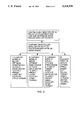
- FIG. 3 is a block diagram showing basic control functions of a hand-held scanner speed control system of one embodiment
- FIG. 4 is a block diagram showing basic control functions of a hand-held scanner speed control system of a second embodiment
- FIG. 5 is a block diagram showing the basic operating components of the hand-held scanner
- FIG. 6 is a graph illustrating applied motor torque as a function of scanning speed according to the control philosophy of FIG. 3;
- FIG. 7 is a graph illustrating one example of applied motor torque as a function of scanning speed according to the control philosophy of FIG. 4.
- FIGS. 1, 2 and 5 illustrate various components of a hand-held optical scanner 10 which comprises an optical sensor assembly (photoelectric conversion device) 101 for generating a data signal representative of a scanned object 11 such as the page of a book.
- the scanner has a housing 12 which supports the optical sensor assembly 80.
- a drive roller assembly 30, 32, 40, 42, etc. is operably mounted on the scanner housing 12 and enables the housing 12 to be rollingly displaced across an object 11 in a predetermined scan direction 13.
- a displacement sensing device such as an encoder unit 70, senses the angular displacement of the drive rollers and generates a signal representation thereof.
- a motor 50 is drivingly linked to the drive rollers 30, 32, etc. for applying driving torque thereto.
- a control assembly actuates the motor 50 for angularly accelerating and decelerating the drive rollers so as to provide tactile feed back to urge an operator to hand displace the housing 12 across the scanned object 11 within a predetermined speed range which is optimal for scanning.
- the speed range is preferably selected to be a relatively small speed range just below the maximum scanning speed at which the unit can operate properly based upon the operating interval of the optical sensor assembly (photoelectric conversion device) 101.
- FIG. 1 illustrates a hand-held optical scanner 10 being used to scan a scan object 11 such as the page of a book.
- the hand-held optical scanner has an elongate, generally box-shaped housing 12 with an open or transparent bottom face 14.
- the housing has a central longitudinal axis XX extending in a direction parallel to scan lines on the object which are imaged and perpendicular to a scanning direction 13 (the direction in which the scanner is moved during a scanning operation).
- the scanner has a central lateral axis YY extending perpendicular to the longitudinal axis XX.
- a scan on/off switch 17 may be provided on the housing or may be incorporated into a roller suspension system (not shown) such that the scanner is enabled for scanning by application of downward force to the scanner by the operator.
- a pair of rotatable shafts 16, 18 extending parallel to central longitudinal axis XX are rotatably supported by support blocks 20 (only one shown) which are fixedly mounted at opposite end portions 22, 24 of the housing.
- a plurality of rollers 30, 32, 34, 40, 42, 44, 46 are fixedly attached to the shafts 16, 18 so as to rotate therewith.
- the rollers may be constructed from rubber, plastic or other suitable material having a coefficient of friction sufficient to non-slippingly engage the surface of a paper document during scanning displacement under normal operating conditions. However, the coefficient of friction of the rollers is sufficiently low so that the rollers will slide on the paper document under certain high speed or high acceleration operating conditions described in detail below.
- a motor 50 is fixedly mounted within the housing 12.
- the motor has a rotatable drive shaft 52 which, in the illustrated embodiment, is arranged parallel to housing axis YY.
- the motor 50 may be a DC motor of a type commercially available such as that sold under the product designation model no. 16.11.182 by Buehler Products, Inc., P.O. Box 33400, Raleigh, N.C.
- a drive shaft gear 54 is fixedly attached to the drive shaft 52 and engages a gear 56 which is fixedly attached to a laterally disposed shaft 58 which may be journaled to forward and rear support blocks (not shown) which are fixedly associated with forward and rear portions of the housing.
- Identical gears 62, 64 are fixedly mounted on opposite ends of shaft 58 and are drivingly engaged with identical gears 66, 68 fixedly mounted on shafts 16 and 18, respectively.
- Drive shafts 16 and 18 are thus rotated by the DC motor in the same direction at identical angular velocities which are directly proportional to the angular velocity of DC motor drive shaft 52.
- a conventional encoder unit 70 is operably associated with motor drive shaft 52 or another shaft, such as 58, 16, 18 of the drive system and provides a pulsed encoder output signal which is representative of angular displacement of drive rollers 30, 32, 40, 42, etc.
- An optical assembly 80 shown schematically in FIG. 5, is situated within the housing and has an elongate scanning head (not shown) which may be of conventional construction and which is positioned between drive shafts 16, 18 extending parallel thereto.
- the optical assembly comprises a light source 82 in the scanning head which illuminates a current scan line portion of the document which is being scanned.
- the optical assembly also comprises an imaging assembly 84, which may comprise a conventional scanner lens assembly, which images the current scan line onto the image plane of a photoelectric conversion device 101 such as a conventional CCD array.
- FIGS. 3 and 6 illustrate the basic operations performed by the scanner speed control system of one embodiment.
- the amount of angular displacement of the drive rollers is continuously monitored by use of encoder 70 and associated counter 116, FIG. 5.
- the first time derivative of roller angular displacement, i.e. angular velocity, is determined by use of signals from counter 116 and clock 118.
- DC motor 50 is actuated to apply torque of a preselected value (either positive, or negative, or zero) to drive rollers 30, 40, etc. based upon a comparison of the current value of roller angular velocity to a predetermined optimal speed range 97.
- the optimal speed range 97 is a relatively small speed range which encompasses a target speed 98 which is slightly less than the maximum speed 99 at which the scanner can operate based upon the sampling rate of the photoelectric conversion device.
- the target speed 98 may be 95% of the maximum speed 99 and the optimal speed range 97 may extend from 90% of maximum speed 99 to 99% of maximum speed 99.
- the drive motor 50 is actuated to apply an accelerating torque to the drive rollers whenever the drive rollers are being moved at a speed below the preselected optimal range 97 of scanning speeds.
- the motor is actuated to apply zero torque to the drive rollers within the preselected optimal range 97 of scanning speeds.
- the motor is actuated to apply a constant smaller decelerating torque when the scanner rollers are moved at a speed above target speed, but within the preselected optimal range.
- a constant relatively high decelerating torque is applied at scanning speeds above the optimal range 97. Variations of this general control philosophy are used in more complex embodiments of the invention to anticipate potential overshoots and undershoots of the optimal speed range, such as discussed below.
- the signals from encoder 70 and clock 118 are used to determine both the first and second time derivates of roller displacement, i.e. the angular velocity and angular acceleration of the drive rollers.
- the current velocity and acceleration values are then both used to determine the magnitude and direction of motor torque to be applied to the drive rollers.
- the velocity and acceleration values may be applied to a predetermined algorithm or look-up table to determine the drive motor torque to be applied. As the result of using acceleration as well as velocity in determining motor response, it may be seen from FIG. 7 that a central envelope is produced in the roller speed region near the optimal speed range 97.
- leading (right edge) represents the motor torque response when the operator is applying a substantial negative acceleration force to the scanner and the trailing (left) edge represents the motor torque response when the operator is applying a substantial accelerating force to the scanner.
- acceleration as a control variable increases the effectiveness of the motor response in maintaining the operator within the optimal speed range.
- time derivatives of displacement could also be used in a speed control system but are unlikely to significantly increase control system effectiveness.
- a microprocessor may use this value to determine the needed input energy.
- the amount of energy input to the motor may be controlled by varying the voltage of the associated motor power source or, as described below, by pulsing a constant voltage energy supply to effectively provide a variable voltage.
- FIG. 5 shows a block diagram of the speed control system of the hand-held scanner of FIG. 1.
- a DC motor 50 is responsive to a voltage supplied from a battery 90 through a pulse width modulator 123 and supplies an angular velocity to the gear and roller assembly 104 which act to move optical assembly 80 and photoelectric conversion device 101 along the document 11 to be copied.
- the photoelectric conversion device 101 is an image receiving device such as a charge coupled device (CCD).
- CCD charge coupled device
- a CCD operates to generate a data signal representative of optical images which are impinged thereon during successive operating intervals. Thus, a "picture" of a small portion of a scanned document (a scan line) is "taken" during each operating interval.
- the data signal is therefore representative of a series of pictures of scan line portions of a document which are generated as the scanner 10 is moved across the document.
- a typical CCD image sensing device takes a "picture" of the document approximately every millisecond. It will be readily apparent that the speed at which the hand-held scanner is moved across the document is critical because it determines the effective width of each scan line for which data is generated. If the scanner is moved too quickly, erratically or in reverse, information from the document will be lost. If the scanner is moved too slowly, redundant information will be gathered with a resulting loss in scanner performance. Therefore, the objective of the speed control system on the hand-held scanner is to urge the user to maintain an optimal forward speed. To this end, the speed control system must sample drive roller velocity and preferably, also drive roller acceleration, process this data and supply a positive or negative voltage to the motor, such that the torque produced by the motor helps the operator adjust the speed of the scanner.
- the movement of the scanner is tracked by means of a quadrature encoder 70 which is designed to provide two pulses that are 90 degrees out of phase.
- the encoder resolution and the drive gear ratio and roller circumference are such that the first pulse or the A pulse provides a rising edge every 13.123 mm of scanner travel which is the scan rate along a document for best image transfer results.
- the second pulse or the B pulse maintains and increments a 16 bit position counter 116 on every rising edge of the A pulse when the scanner is moving forward.
- the B pulse counter will de-increment on the falling edge of the A pulse when the scanner is moving backward, which should ordinarily not happen.
- the position counter will be reset.
- the quadrature encoder acts as a position displacement counter and direction indicator.
- a counter 116 will measure the time between A pulses.
- the counter 116 may run at about 200 kHz and will reset on the rising edge of the A pulse when the scanner is moving forward. If the scanner is moving in reverse, the counter will be reset on the falling edge of the A pulse.
- the counter value is then differentiated once to obtain velocity and twice to obtain acceleration. The differentiation is conducted by the differentiator 117. The position, direction, velocity and/or acceleration are then stored in RAM 120.
- the acceleration will not be calculated and no allowance will be made for the acceleration of the scanner.
- Such a system would regulate the user's speed, but may over or under shoot the target speed when the user applies too much or too little force during the scan.
- the overshoot can be minimized and a target speed can be selected which is closer to the maximum scan speed.
- the target speed should be set to slightly less than the maximum speed that the photoelectrical conversion device 11 is capable of processing data. Then, any minor overshoot of target speed will not result in the loss of data.
- a digital signal processor or microprocessor 122 retrieves the velocity or velocity and acceleration information and converts these values to motor angular velocity and motor angular acceleration through use of an appropriate algorithm or look-up table.
- angular velocity at count zero (W 0 ) is 13.123 mm times the gear ratio between drive shafts 16, 18 and motor drive shaft 52 divided by the velocity at count zero (V 0 ) times 4.571 ⁇ s times the roller radius.
- the angular acceleration at count zero (a 0 ) is the angular velocity at count zero (W 0 ) minus the angular velocity at the previous count (W -1 ) divided by the velocity at count zero (V 0 ) times 4.571 ⁇ s.
- Both of the above conversions can be performed more efficiently by the microprocessor 122 via a look-up table.
- the microprocessor will then calculate the voltage required to provide a preselected torque from the motor to provide tactile feedback to the operator so that he may be urged to operate the scanner at near the target speed.
- "fuzzy logic” is applied and then a table look-up operation is performed to find the desired torque voltage. Fuzzy logic is a control system whereby the designer establishes rules and tables such that a given velocity and acceleration will produce a predetermined torque voltage. Fuzzy logic reduces the amount of math required by the microprocessor, thus the microprocessor design and programming are simpler. Also, the response time is greatly enhanced with fuzzy logic.
- a pulse width modulator (PWM) 123 capable of storing 256 discrete values, may regulate the effective voltage and voltage polarity seen by the motor.
- PWM pulse width modulator
- the voltage provided to the motor (V motor ) is calculated by multiplying N 0-255 by 12 (maximum motor voltage) and dividing by 255, which results in a number 0-12.
- N 0-255 is calculated by multiplying the torque constant (K) of the motor by the angular velocity at count zero (W 0 ) and adding the torque voltage (V torque ).
- the microprocessor programs the pulse width modulator with an appropriate duty cycle based upon this calculated motor voltage.
- An appropriate switch 92 setting is also selected based upon the calculated motor voltage, as described below.
- FIG. 5 also shows the manner in which the motor 50 may be actuated to provide decelerating torque to the drive rollers.
- the pulse width modulator is switched out and that motor terminal is connected to ground.
- a microprocessor responsive switching assembly 92 has a first operating state in which motor 50 is connected to neither battery 90 nor ground 93; a second operating state in which motor 50 is connected to ground 93 only; and a third operating state in which motor 50 is connected (in reverse) to battery 90 only.
- the switch is placed in a selected operating state by a control signal from microprocessor 122. In the first operating state the motor 50 is "free-wheeling" and provides no significant torque to the drive rollers. In the second operating state a first negative torque is provided by the motor.
- a second relatively larger magnitude negative torque is provided by the motor.
- the negative torque increases in magnitude with roller speed since generator output increases with speed.
- a variable resistance switching assembly connecting motor 50 and battery 90 is used to provide a selectively variable negative torque.
- deceleration torque is produced using the pulse width modulator in conjunction with appropriate switch setting.
- the battery 90 is an onboard battery and provides electrical energy to all of the scanner components which use electrical energy.
- Another function that the microprocessor 122 must perform is to interrupt the line selector 102 on every encoder rising edge, i.e. every 13.123 mm of scanner travel, and instruct the line selector to select a line of scan data to process and store the line scan data (in mass storage 119) for final image output as indicated at 121.
- the line selector will select two lines of data, the one immediately before and the one immediately after the encoder pulses, for example, and average the data from the two lines selected. This embodiment produces a more precise image than a single line per pulse.
- the position counter 116, the differentiator 117, the clock 118, the RAM 120, the mass storage 119, the microprocessor (or DSP) 122, the switch 92 and the pulse width modulator 123 would all be implemented in an Application Specific Integrated Circuit (ASIC), which would save space and allow for a smaller, lighter scan device. Also, designing the above speed control circuitry into an ASIC would result in significant manufacturing and component cost savings during mass production.
- ASIC Application Specific Integrated Circuit
- the image signal produced by the above described method and apparatus may be internally stored on a mass storage device 119 mounted within the scanner housing and may also be transmitted to attached devices such as a personal computer (not shown) for further processing (e.g. OCR) or for storage on suitable media such as a hard drive, floppy disk or ROM disk; or for providing a visual display such as through an attached CRT or printer.
- attached devices such as a personal computer (not shown) for further processing (e.g. OCR) or for storage on suitable media such as a hard drive, floppy disk or ROM disk; or for providing a visual display such as through an attached CRT or printer.
Abstract
Description
Number (N.sub.0-255)=K×W.sub.0 +V.sub.torque)
Claims (18)
Priority Applications (4)
| Application Number | Priority Date | Filing Date | Title |
|---|---|---|---|
| US08/031,771 US5306908A (en) | 1993-03-15 | 1993-03-15 | Manually operated hand-held optical scanner with tactile speed control assembly |
| DE69412315T DE69412315T2 (en) | 1993-03-15 | 1994-03-02 | Optical handheld scanner with speed control |
| EP94301507A EP0616461B1 (en) | 1993-03-15 | 1994-03-02 | Hand-held optical scanner with speed control assembly |
| JP6064602A JPH0774896A (en) | 1993-03-15 | 1994-03-08 | Optical scanner for grip |
Applications Claiming Priority (1)
| Application Number | Priority Date | Filing Date | Title |
|---|---|---|---|
| US08/031,771 US5306908A (en) | 1993-03-15 | 1993-03-15 | Manually operated hand-held optical scanner with tactile speed control assembly |
Publications (1)
| Publication Number | Publication Date |
|---|---|
| US5306908A true US5306908A (en) | 1994-04-26 |
Family
ID=21861301
Family Applications (1)
| Application Number | Title | Priority Date | Filing Date |
|---|---|---|---|
| US08/031,771 Expired - Lifetime US5306908A (en) | 1993-03-15 | 1993-03-15 | Manually operated hand-held optical scanner with tactile speed control assembly |
Country Status (4)
| Country | Link |
|---|---|
| US (1) | US5306908A (en) |
| EP (1) | EP0616461B1 (en) |
| JP (1) | JPH0774896A (en) |
| DE (1) | DE69412315T2 (en) |
Cited By (44)
| Publication number | Priority date | Publication date | Assignee | Title |
|---|---|---|---|---|
| US5459588A (en) * | 1993-08-18 | 1995-10-17 | Logitech, Inc. | Apparatus and method for clutchless motor driven hand held scanner |
| US5475503A (en) * | 1994-02-08 | 1995-12-12 | Logitech, Inc. | Roller for optical scanner |
| WO1996027257A2 (en) * | 1995-03-02 | 1996-09-06 | Hewlett-Packard Company | Image scanning device and method |
| US5646402A (en) * | 1995-09-05 | 1997-07-08 | Hewlett-Packard Company | Expandable hand-held scanning device |
| EP0786893A2 (en) * | 1996-01-29 | 1997-07-30 | Hewlett-Packard Company | Hand-held scanning device |
| US5744795A (en) * | 1995-07-31 | 1998-04-28 | Hewlett-Packard Company | Illumination strobing in a scanner to improve image sharpness and power consumption |
| US5777321A (en) * | 1996-01-29 | 1998-07-07 | Hewlett-Packard Company | Scanning device with non-contact optical components |
| US5923444A (en) * | 1997-04-14 | 1999-07-13 | Hewlett-Packard Company | Floating image head design for portable scanner |
| US5995243A (en) * | 1997-06-18 | 1999-11-30 | Hewlett-Packard Company | Illumination system with white level calibration for hand-held scanner |
| US6002124A (en) * | 1998-03-20 | 1999-12-14 | Hewlett-Packard Company | Portable image scanner with optical position sensors |
| US6010072A (en) * | 1996-05-20 | 2000-01-04 | Nec Corporation | Hand scanner movable over a document without meandering |
| US6033086A (en) * | 1998-04-30 | 2000-03-07 | Hewlett-Packard Company | Compact illumination system for image scanner |
| US6064062A (en) * | 1998-06-02 | 2000-05-16 | Hewlett-Packard Company | Optical stray light baffle for image scanner |
| US6064496A (en) * | 1997-06-18 | 2000-05-16 | Hewlett-Packard Company | Scanning device with floating window member |
| EP1026620A2 (en) * | 1999-02-05 | 2000-08-09 | Hewlett-Packard Company | Expandable hand scanner with lens reduction optics |
| US6118553A (en) * | 1998-01-28 | 2000-09-12 | Hewlett-Packard Company | Compact motor drive and active speed governor with optical encoder for scanner mechanisms |
| US6147343A (en) * | 1998-07-23 | 2000-11-14 | Hewlett-Packard Company | Photoelectric imaging method and apparatus |
| US6160250A (en) * | 1999-03-31 | 2000-12-12 | Hewlett-Packard Company | Integrated optical imaging assembly |
| US6229137B1 (en) | 1998-09-14 | 2001-05-08 | Hewlett-Packard Company | Scan line illumination system utilizing hollow reflector |
| US6249360B1 (en) | 1997-04-14 | 2001-06-19 | Hewlett-Packard Company | Image scanning device and method |
| US6259826B1 (en) | 1997-06-12 | 2001-07-10 | Hewlett-Packard Company | Image processing method and device |
| US6265706B1 (en) | 1999-07-12 | 2001-07-24 | Hewlett-Packard Company | Edge to edge image sensor and navigator for portable scanner |
| US6270013B1 (en) * | 1996-07-22 | 2001-08-07 | Wizcom Technologies, Ltd. | Hand-holdable optical scanner particularly useful as electronic translator |
| US6292274B1 (en) | 1998-12-11 | 2001-09-18 | Hewlett-Packard Company | Portable scanner with tilting body design |
| US6330082B1 (en) | 1998-08-28 | 2001-12-11 | Hewlett-Packard Company | Converter for optical scanner |
| US6350980B1 (en) | 1999-08-27 | 2002-02-26 | Hewlett-Packard Company | Imaging assembly with a side mounted optical detector for a scanner |
| US6357939B1 (en) | 2001-02-02 | 2002-03-19 | Hewlett-Packard Company | Method of and apparatus for handheld printing of images on a media |
| US6426498B1 (en) | 2000-04-03 | 2002-07-30 | Hewlett-Packard Co. | Optics module for optical scanning device |
| US6429422B1 (en) | 1999-11-12 | 2002-08-06 | Hewlett-Packard Company | Scanner navigation system with variable aperture |
| US20020180691A1 (en) * | 2001-05-30 | 2002-12-05 | Wong Yoon Kean | Optical sensor based user interface for a portable electronic device |
| US6527182B1 (en) * | 1999-06-04 | 2003-03-04 | Fujitsu Limited | Image reading apparatus and image processing apparatus |
| US6639203B1 (en) | 1997-07-02 | 2003-10-28 | Hewlett-Packard Development Company, L.P. | Catadioptric lens system for a scanning device |
| US6648226B2 (en) * | 2000-09-05 | 2003-11-18 | Canon Kabushiki Kaisha | Image reading apparatus and method |
| US20040211891A1 (en) * | 2002-02-07 | 2004-10-28 | Erhard Hoffmann | Hand-operated device |
| US20050022686A1 (en) * | 2003-07-28 | 2005-02-03 | Dreampatch, Llc | Apparatus, method, and computer program product for animation pad transfer |
| US20050036165A1 (en) * | 2003-08-12 | 2005-02-17 | Charles Jia | Scanning to storage medium using scanning device |
| US6878922B1 (en) | 1998-12-23 | 2005-04-12 | Hewlett-Packard Development Company, L.P. | Optical system for compensating for non-uniform illumination of an object |
| US20050088683A1 (en) * | 2002-02-13 | 2005-04-28 | Kia Silverbrook | Manually operable printer-scanner |
| US20060278714A1 (en) * | 2005-06-14 | 2006-12-14 | David Ho | Portable communication apparatus having optics character recognition function |
| US20070187503A1 (en) * | 2006-02-14 | 2007-08-16 | Ching-Hui Chen | Thin MFP (multifunction peripheral) |
| US20090237446A1 (en) * | 2002-02-13 | 2009-09-24 | Silverbrook Research Pty Ltd. | Capping Device For Hand-Held Printer |
| CN102131030A (en) * | 2011-03-18 | 2011-07-20 | 孟克巴依尔 | Portable duplicating device |
| US20120229821A1 (en) * | 2011-03-10 | 2012-09-13 | Shih-Huang Chen | Integrated contact image sensor module and image scanning system |
| US10019839B2 (en) | 2016-06-30 | 2018-07-10 | Microsoft Technology Licensing, Llc | Three-dimensional object scanning feedback |
Citations (7)
| Publication number | Priority date | Publication date | Assignee | Title |
|---|---|---|---|---|
| US3541248A (en) * | 1967-09-29 | 1970-11-17 | Xerox Corp | Document abstractor with hand-held optical scanner with constant resolution scanning |
| US4703186A (en) * | 1984-07-12 | 1987-10-27 | Matsushita Electric Industrial Co., Ltd. | Hand-held scanner with a speed control device |
| US4709144A (en) * | 1986-04-02 | 1987-11-24 | Hewlett-Packard Company | Color imager utilizing novel trichromatic beamsplitter and photosensor |
| US4793812A (en) * | 1987-10-05 | 1988-12-27 | Xerox Corporation | Hand held optical scanner for omni-font character recognition |
| US4870268A (en) * | 1986-04-02 | 1989-09-26 | Hewlett-Packard Company | Color combiner and separator and implementations |
| US4926041A (en) * | 1989-07-20 | 1990-05-15 | Hewlett-Packard Company | Optical scanner |
| US5182450A (en) * | 1991-11-06 | 1993-01-26 | Primax Electronics Ltd. | Handheld image scanner with automatic movement control |
Family Cites Families (5)
| Publication number | Priority date | Publication date | Assignee | Title |
|---|---|---|---|---|
| WO1987007805A1 (en) * | 1986-06-12 | 1987-12-17 | Casio Computer, Co., Ltd. | Manually scanned image data processor |
| JPS6342275A (en) * | 1986-08-07 | 1988-02-23 | Mitsubishi Electric Corp | Handy image reader |
| WO1988001123A1 (en) * | 1986-08-07 | 1988-02-11 | Mitsubishi Denki Kabushiki Kaisha | Handy image reader |
| US4967188A (en) * | 1989-07-26 | 1990-10-30 | Ncr Corporation | Method for detecting low battery voltage in portable scanning systems |
| JPH04319857A (en) * | 1991-04-19 | 1992-11-10 | Canon Inc | Image reader |
-
1993
- 1993-03-15 US US08/031,771 patent/US5306908A/en not_active Expired - Lifetime
-
1994
- 1994-03-02 EP EP94301507A patent/EP0616461B1/en not_active Expired - Lifetime
- 1994-03-02 DE DE69412315T patent/DE69412315T2/en not_active Expired - Fee Related
- 1994-03-08 JP JP6064602A patent/JPH0774896A/en active Pending
Patent Citations (7)
| Publication number | Priority date | Publication date | Assignee | Title |
|---|---|---|---|---|
| US3541248A (en) * | 1967-09-29 | 1970-11-17 | Xerox Corp | Document abstractor with hand-held optical scanner with constant resolution scanning |
| US4703186A (en) * | 1984-07-12 | 1987-10-27 | Matsushita Electric Industrial Co., Ltd. | Hand-held scanner with a speed control device |
| US4709144A (en) * | 1986-04-02 | 1987-11-24 | Hewlett-Packard Company | Color imager utilizing novel trichromatic beamsplitter and photosensor |
| US4870268A (en) * | 1986-04-02 | 1989-09-26 | Hewlett-Packard Company | Color combiner and separator and implementations |
| US4793812A (en) * | 1987-10-05 | 1988-12-27 | Xerox Corporation | Hand held optical scanner for omni-font character recognition |
| US4926041A (en) * | 1989-07-20 | 1990-05-15 | Hewlett-Packard Company | Optical scanner |
| US5182450A (en) * | 1991-11-06 | 1993-01-26 | Primax Electronics Ltd. | Handheld image scanner with automatic movement control |
Cited By (63)
| Publication number | Priority date | Publication date | Assignee | Title |
|---|---|---|---|---|
| US5459588A (en) * | 1993-08-18 | 1995-10-17 | Logitech, Inc. | Apparatus and method for clutchless motor driven hand held scanner |
| US5475503A (en) * | 1994-02-08 | 1995-12-12 | Logitech, Inc. | Roller for optical scanner |
| US6005681A (en) * | 1995-03-02 | 1999-12-21 | Hewlett-Packard Company | Image scanning device and method |
| WO1996027257A2 (en) * | 1995-03-02 | 1996-09-06 | Hewlett-Packard Company | Image scanning device and method |
| WO1996027257A3 (en) * | 1995-03-02 | 1997-02-20 | Hewlett Packard Co | Image scanning device and method |
| CN1120444C (en) * | 1995-03-02 | 2003-09-03 | 惠普公司 | Freehand image scanning device and method |
| US5744795A (en) * | 1995-07-31 | 1998-04-28 | Hewlett-Packard Company | Illumination strobing in a scanner to improve image sharpness and power consumption |
| US5646402A (en) * | 1995-09-05 | 1997-07-08 | Hewlett-Packard Company | Expandable hand-held scanning device |
| EP0786893A2 (en) * | 1996-01-29 | 1997-07-30 | Hewlett-Packard Company | Hand-held scanning device |
| US5723859A (en) * | 1996-01-29 | 1998-03-03 | Hewlett-Packard Company | Line contact hand-held scanning device and method having a light path substantially perpendicular to the orientation of the object at a line portion |
| US5777321A (en) * | 1996-01-29 | 1998-07-07 | Hewlett-Packard Company | Scanning device with non-contact optical components |
| EP0786893A3 (en) * | 1996-01-29 | 1999-03-31 | Hewlett-Packard Company | Hand-held scanning device |
| US6010072A (en) * | 1996-05-20 | 2000-01-04 | Nec Corporation | Hand scanner movable over a document without meandering |
| US6270013B1 (en) * | 1996-07-22 | 2001-08-07 | Wizcom Technologies, Ltd. | Hand-holdable optical scanner particularly useful as electronic translator |
| US5923444A (en) * | 1997-04-14 | 1999-07-13 | Hewlett-Packard Company | Floating image head design for portable scanner |
| US6249360B1 (en) | 1997-04-14 | 2001-06-19 | Hewlett-Packard Company | Image scanning device and method |
| US6259826B1 (en) | 1997-06-12 | 2001-07-10 | Hewlett-Packard Company | Image processing method and device |
| US6064496A (en) * | 1997-06-18 | 2000-05-16 | Hewlett-Packard Company | Scanning device with floating window member |
| US5995243A (en) * | 1997-06-18 | 1999-11-30 | Hewlett-Packard Company | Illumination system with white level calibration for hand-held scanner |
| US6639203B1 (en) | 1997-07-02 | 2003-10-28 | Hewlett-Packard Development Company, L.P. | Catadioptric lens system for a scanning device |
| US6118553A (en) * | 1998-01-28 | 2000-09-12 | Hewlett-Packard Company | Compact motor drive and active speed governor with optical encoder for scanner mechanisms |
| US6002124A (en) * | 1998-03-20 | 1999-12-14 | Hewlett-Packard Company | Portable image scanner with optical position sensors |
| US6033086A (en) * | 1998-04-30 | 2000-03-07 | Hewlett-Packard Company | Compact illumination system for image scanner |
| US6064062A (en) * | 1998-06-02 | 2000-05-16 | Hewlett-Packard Company | Optical stray light baffle for image scanner |
| US6147343A (en) * | 1998-07-23 | 2000-11-14 | Hewlett-Packard Company | Photoelectric imaging method and apparatus |
| US6330082B1 (en) | 1998-08-28 | 2001-12-11 | Hewlett-Packard Company | Converter for optical scanner |
| US6229137B1 (en) | 1998-09-14 | 2001-05-08 | Hewlett-Packard Company | Scan line illumination system utilizing hollow reflector |
| US6292274B1 (en) | 1998-12-11 | 2001-09-18 | Hewlett-Packard Company | Portable scanner with tilting body design |
| US6878922B1 (en) | 1998-12-23 | 2005-04-12 | Hewlett-Packard Development Company, L.P. | Optical system for compensating for non-uniform illumination of an object |
| EP1026620A3 (en) * | 1999-02-05 | 2001-10-04 | Hewlett-Packard Company, A Delaware Corporation | Expandable hand scanner with lens reduction optics |
| US6184515B1 (en) | 1999-02-05 | 2001-02-06 | Hewlett-Packard Company | Expandable hand scanner with lens reduction optics |
| EP1026620A2 (en) * | 1999-02-05 | 2000-08-09 | Hewlett-Packard Company | Expandable hand scanner with lens reduction optics |
| US6294776B2 (en) | 1999-03-31 | 2001-09-25 | Hewlett-Packard Company | Integrated optical imaging assembly |
| US6160250A (en) * | 1999-03-31 | 2000-12-12 | Hewlett-Packard Company | Integrated optical imaging assembly |
| US6527182B1 (en) * | 1999-06-04 | 2003-03-04 | Fujitsu Limited | Image reading apparatus and image processing apparatus |
| US6265706B1 (en) | 1999-07-12 | 2001-07-24 | Hewlett-Packard Company | Edge to edge image sensor and navigator for portable scanner |
| US6350980B1 (en) | 1999-08-27 | 2002-02-26 | Hewlett-Packard Company | Imaging assembly with a side mounted optical detector for a scanner |
| US6429422B1 (en) | 1999-11-12 | 2002-08-06 | Hewlett-Packard Company | Scanner navigation system with variable aperture |
| US6426498B1 (en) | 2000-04-03 | 2002-07-30 | Hewlett-Packard Co. | Optics module for optical scanning device |
| US6648226B2 (en) * | 2000-09-05 | 2003-11-18 | Canon Kabushiki Kaisha | Image reading apparatus and method |
| US6357939B1 (en) | 2001-02-02 | 2002-03-19 | Hewlett-Packard Company | Method of and apparatus for handheld printing of images on a media |
| US20020180691A1 (en) * | 2001-05-30 | 2002-12-05 | Wong Yoon Kean | Optical sensor based user interface for a portable electronic device |
| US6816154B2 (en) * | 2001-05-30 | 2004-11-09 | Palmone, Inc. | Optical sensor based user interface for a portable electronic device |
| US20090184942A1 (en) * | 2001-05-30 | 2009-07-23 | Palm, Inc. | Optical sensor based user interface for a portable electronic device |
| US7411583B1 (en) | 2001-05-30 | 2008-08-12 | Palm, Inc. | Optical sensor based user interface for a portable electronic device |
| US20040211891A1 (en) * | 2002-02-07 | 2004-10-28 | Erhard Hoffmann | Hand-operated device |
| US7414235B2 (en) * | 2002-02-07 | 2008-08-19 | Robert Bosch Gmbh | Handheld locating device with a sensor for detecting motion parameters |
| US20050088683A1 (en) * | 2002-02-13 | 2005-04-28 | Kia Silverbrook | Manually operable printer-scanner |
| US8011782B2 (en) | 2002-02-13 | 2011-09-06 | Silverbrook Research Pty Ltd | Elongate hand-held printer device with an optical encoder wheel |
| US7426050B2 (en) * | 2002-02-13 | 2008-09-16 | Silverbrook Research Pty Ltd | Manually operable printer-scanner |
| US20080291258A1 (en) * | 2002-02-13 | 2008-11-27 | Silverbrook Research Pty Ltd | Elongate hand-held printer device with an optical encoder wheel |
| US8382278B2 (en) | 2002-02-13 | 2013-02-26 | Silverbrook Research Pty Ltd | Capping device for hand-held printer |
| US20090237446A1 (en) * | 2002-02-13 | 2009-09-24 | Silverbrook Research Pty Ltd. | Capping Device For Hand-Held Printer |
| US8042934B2 (en) | 2002-02-13 | 2011-10-25 | Silverbrook Research Pty Ltd | Capping device for hand-held printer |
| US20050022686A1 (en) * | 2003-07-28 | 2005-02-03 | Dreampatch, Llc | Apparatus, method, and computer program product for animation pad transfer |
| US20050036165A1 (en) * | 2003-08-12 | 2005-02-17 | Charles Jia | Scanning to storage medium using scanning device |
| US7417751B2 (en) | 2003-08-12 | 2008-08-26 | Hewlett-Packard Development Company, L.P. | Scanning to storage medium using scanning device |
| US20060278714A1 (en) * | 2005-06-14 | 2006-12-14 | David Ho | Portable communication apparatus having optics character recognition function |
| US7559476B2 (en) * | 2006-02-14 | 2009-07-14 | Lite-On Technology Corporation | Thin MFP (multifunction peripheral) |
| US20070187503A1 (en) * | 2006-02-14 | 2007-08-16 | Ching-Hui Chen | Thin MFP (multifunction peripheral) |
| US20120229821A1 (en) * | 2011-03-10 | 2012-09-13 | Shih-Huang Chen | Integrated contact image sensor module and image scanning system |
| CN102131030A (en) * | 2011-03-18 | 2011-07-20 | 孟克巴依尔 | Portable duplicating device |
| US10019839B2 (en) | 2016-06-30 | 2018-07-10 | Microsoft Technology Licensing, Llc | Three-dimensional object scanning feedback |
Also Published As
| Publication number | Publication date |
|---|---|
| DE69412315T2 (en) | 1998-12-17 |
| JPH0774896A (en) | 1995-03-17 |
| DE69412315D1 (en) | 1998-09-17 |
| EP0616461B1 (en) | 1998-08-12 |
| EP0616461A2 (en) | 1994-09-21 |
| EP0616461A3 (en) | 1994-10-26 |
Similar Documents
| Publication | Publication Date | Title |
|---|---|---|
| US5306908A (en) | Manually operated hand-held optical scanner with tactile speed control assembly | |
| US5381020A (en) | Hand-held optical scanner with onboard battery recharging assembly | |
| EP0955769B1 (en) | Optical scanner including exposure control | |
| US4748514A (en) | Variable rate scanning control | |
| EP0399651B1 (en) | Apparatus and method of scanning image data | |
| EP0761494A3 (en) | Multiple speed vehicle seat memory control apparatus | |
| EP0576226B1 (en) | Method and apparatus for reading image of image scanner-reader | |
| US4703186A (en) | Hand-held scanner with a speed control device | |
| EP0062479B1 (en) | Raster scanner apparatus and method | |
| US5182450A (en) | Handheld image scanner with automatic movement control | |
| EP1536290A3 (en) | Stage apparatus and linear motor | |
| TW404383U (en) | Electric bicycle | |
| EP0282041A3 (en) | A yaw motion control device for a vehicle | |
| GB2092315A (en) | Variable magnification copying machine | |
| US6118553A (en) | Compact motor drive and active speed governor with optical encoder for scanner mechanisms | |
| GB1433340A (en) | X-ray apparatus | |
| CA1307803C (en) | Web guide apparatus | |
| US4748555A (en) | Control unit for a moving body | |
| EP0899940A3 (en) | Facsimile apparatus | |
| US4428288A (en) | Adjustable drive system for matching surface speeds of a transfer roll and plate roll and method thereof | |
| DE69304755T2 (en) | Control device for cylinder phase adjustment of a printing press | |
| US4424744A (en) | Adjustable drive system for matching surface speeds of a transfer roll and plate roll and method thereof | |
| US4896167A (en) | Image recording apparatus | |
| JPH0855186A (en) | Speed-limit-roller assembly for grip-type scanner | |
| US4313676A (en) | Method of automatically adjusting a picture reproducing apparatus |
Legal Events
| Date | Code | Title | Description |
|---|---|---|---|
| STPP | Information on status: patent application and granting procedure in general |
Free format text: APPLICATION UNDERGOING PREEXAM PROCESSING |
|
| AS | Assignment |
Owner name: HEWLETT-PACKARD COMPANY, CALIFORNIA Free format text: ASSIGNMENT OF ASSIGNORS INTEREST;ASSIGNORS:MCCONICA, CHARLES H.;AAS, ERIC F.;KOCHIS, RICHARD L.;AND OTHERS;REEL/FRAME:006741/0977 Effective date: 19930312 |
|
| FEPP | Fee payment procedure |
Free format text: PAYOR NUMBER ASSIGNED (ORIGINAL EVENT CODE: ASPN); ENTITY STATUS OF PATENT OWNER: LARGE ENTITY |
|
| FPAY | Fee payment |
Year of fee payment: 4 |
|
| AS | Assignment |
Owner name: HEWLETT-PACKARD COMPANY, COLORADO Free format text: MERGER;ASSIGNOR:HEWLETT-PACKARD COMPANY;REEL/FRAME:011523/0469 Effective date: 19980520 |
|
| FPAY | Fee payment |
Year of fee payment: 8 |
|
| FPAY | Fee payment |
Year of fee payment: 12 |
|
| AS | Assignment |
Owner name: HEWLETT-PACKARD DEVELOPMENT COMPANY, L.P., TEXAS Free format text: ASSIGNMENT OF ASSIGNORS INTEREST;ASSIGNOR:HEWLETT-PACKARD COMPANY;REEL/FRAME:026945/0699 Effective date: 20030131 |