US5326253A - Partial combustion process and a catalyst structure for use in the process - Google Patents
Partial combustion process and a catalyst structure for use in the process Download PDFInfo
- Publication number
- US5326253A US5326253A US07/617,975 US61797590A US5326253A US 5326253 A US5326253 A US 5326253A US 61797590 A US61797590 A US 61797590A US 5326253 A US5326253 A US 5326253A
- Authority
- US
- United States
- Prior art keywords
- catalyst
- palladium
- temperature
- combustion
- gas mixture
- Prior art date
- Legal status (The legal status is an assumption and is not a legal conclusion. Google has not performed a legal analysis and makes no representation as to the accuracy of the status listed.)
- Expired - Lifetime
Links
Images


Classifications
-
- B—PERFORMING OPERATIONS; TRANSPORTING
- B01—PHYSICAL OR CHEMICAL PROCESSES OR APPARATUS IN GENERAL
- B01D—SEPARATION
- B01D53/00—Separation of gases or vapours; Recovering vapours of volatile solvents from gases; Chemical or biological purification of waste gases, e.g. engine exhaust gases, smoke, fumes, flue gases, aerosols
- B01D53/34—Chemical or biological purification of waste gases
- B01D53/74—General processes for purification of waste gases; Apparatus or devices specially adapted therefor
- B01D53/86—Catalytic processes
- B01D53/8621—Removing nitrogen compounds
- B01D53/8625—Nitrogen oxides
- B01D53/8628—Processes characterised by a specific catalyst
-
- B—PERFORMING OPERATIONS; TRANSPORTING
- B01—PHYSICAL OR CHEMICAL PROCESSES OR APPARATUS IN GENERAL
- B01J—CHEMICAL OR PHYSICAL PROCESSES, e.g. CATALYSIS OR COLLOID CHEMISTRY; THEIR RELEVANT APPARATUS
- B01J23/00—Catalysts comprising metals or metal oxides or hydroxides, not provided for in group B01J21/00
- B01J23/38—Catalysts comprising metals or metal oxides or hydroxides, not provided for in group B01J21/00 of noble metals
- B01J23/40—Catalysts comprising metals or metal oxides or hydroxides, not provided for in group B01J21/00 of noble metals of the platinum group metals
- B01J23/44—Palladium
-
- B—PERFORMING OPERATIONS; TRANSPORTING
- B01—PHYSICAL OR CHEMICAL PROCESSES OR APPARATUS IN GENERAL
- B01J—CHEMICAL OR PHYSICAL PROCESSES, e.g. CATALYSIS OR COLLOID CHEMISTRY; THEIR RELEVANT APPARATUS
- B01J37/00—Processes, in general, for preparing catalysts; Processes, in general, for activation of catalysts
- B01J37/02—Impregnation, coating or precipitation
- B01J37/0215—Coating
- B01J37/0225—Coating of metal substrates
Definitions
- This invention is both a partial combustion process in which the fuel is partially combusted using specific catalysts and catalytic structures and also a catalyst structure for use in the process.
- the choice of catalysts and supports solves problems in the art dealing with the stability of the overall catalyst structure and ease of catalyst operation.
- the catalyst structure is stable due to its comparatively low operating temperature, has a low temperature at which catalytic combustion begins, and yet is not susceptible to temperature "runaway".
- the combustion gas produced by the catalytic process typically is below the autocombustive temperature for the gas mixture; the gas may be used at that temperature, or fed to other combustion stages for ultimate use in a gas turbine, furnace, boiler, or the like.
- NO x an equilibrium mixture mostly of NO but also containing very minor amounts of NO 2
- NO x may be dealt with either by controlling the combustion process to minimize NO x production or by later removal. Removal of NO x , once produced, is a difficult task because of its relative stability and its low concentration in most exhaust gases.
- One solution found in automobiles is the use of carbon monoxide chemically to reduce NO x to nitrogen while oxidizing the carbon monoxide to carbon dioxide.
- the carbon monoxide concentration is insufficient to react with and to remove the NO x .
- the NO x abatement process chosen must not substantially conflict with the goal for which the combustion gas was created, i.e., the recovery of its heat value in a turbine, boiler, or furnace.
- the process of this invention mixes air and fuel at the beginning of the combustor in a ratio such that the final combustion temperature is, after further combustion step(s), that required by some later process or device which recovers the heat from the combustive gas, e.g., a gas turbine.
- a typical mixture might be methane and air at a volume fuel/volume air ratio of 0.043.
- Such a mixture (after being preheated to 350° C.) would provide a combustion temperature of about 1300° C.
- This mixture passes over a catalyst and is only partially combusted with the catalyst limiting the maximum catalyst temperature to less than about the thermogravimetric analysis (TGA) transition temperature of the reaction:
- this TGA transition temperature is approximately 780° C. to 800° C. in air at one atm and 930° C. to 950° C. in air at ten atm.
- the temperature self-controlling feature of this invention takes place by employing one or more of the following:
- the use of metal substrates has been limited to applications where the adiabatic combustion temperature is below 1100° C. or 1000° C. and where the complete combustion of the fuel/air mixture will result in a substrate temperature that would not damage the metal.
- This limitation caps the final gas temperature that can be achieved or requires the use of staged fuel or air addition further complicating the combustor design.
- the use of the inventive process limits the metal substrate temperature to less than 850° C. at one atm pressure and to less than 950° C. at 16 atm pressure even for fuel/air mixtures with adiabatic combustion temperatures up to 1500° C.
- the inventive process also offers advantage for ceramic substrates since limiting the substrate temperature reduces thermal stress and the propensity for structural failure due to thermal shock during start-up and shutdown of the combustor. This protection is especially important for fuel/air ratios corresponding to adiabatic combustion temperatures of 1300° C. to 1600° C.
- This invention is both a catalyst structure and a partial combustion process in which a fuel/air mixture having a high adiabatic combustion temperature undergoes partial combustion using that catalyst structure.
- the catalyst structure causes the extent of combustion to be self-limiting and, therefore, the temperature of the catalyst structure itself is maintained at a comparatively low temperature, e.g., a temperature significantly below the inherent combustion temperature of the gas passing through the catalyst.
- the catalyst structure comprises palladium on a ceramic or, preferably, a metal support configured such that the feed gas and resulting combustion gas flow easily and quickly through the support.
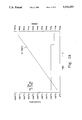
- FIG. 1 is a graph comparing the respective operating temperatures of palladium or platinum catalysts at various of fuel/air ratios.
- FIG. 2A is a graph of the TGA of palladium oxide/palladium at one atm air.
- FIG. 2B is a graph of the TGA of palladium oxide/palladium at one atm of pure O 2 .
- FIG. 3 is a graph of various process outlet temperatures as a function of catalyst preheat temperature for a particular uncoated catalyst.
- FIG. 4 is a graph of various process outlet temperatures as a function of catalyst preheat temperatures for a palladium-containing catalyst prepared using a palladium chloride salt.
- FIGS. 5A and 5B are graphs of LOT and steady state operation temperatures for a zirconia-coated cordierite monolith.
- FIGS. 6A and 6B are graphs of LOT and steady state operation temperatures for a zirconia-coated metal monolith.
- This invention is a catalyst structure and also a partial combustion process in which a fuel/air mixture with a high adiabatic combustion temperature is partially combusted on that specific catalyst structure.
- the structure is a palladium-based catalyst on a ceramic or metal monolith which desirably has been coated with a minor amount (a diffusion barrier) of a non-catalytic metal oxide.
- the process produces an exhaust gas at temperature which may be used either at that temperature or introduced into additional combustion stages for further use in a gas turbine, boiler, or furnace.
- the catalyst comprises palladium on a support.
- the support is first at least partially coated with a coating of an oxidic support material (often called a "washcoat") prior to palladium addition.
- the structure (after the palladium addition) may then be coated with another layer (often called here a "barrier coat").
- Palladium is fairly active as an oxidation catalyst at temperatures of 325° C. (at one atmosphere of air) and lower and consequently is useful in a combustion process as a catalyst for the initial combustion phase. As was discussed above, the catalytic activity of palladium as a fuel oxidation catalyst is believed due to the presence of palladium oxide. Palladium metal does not appear to be a very active as a catalyst except at fairly high temperatures, e.g., substantially above to 800° C. (at one atmosphere). Palladium metal is readily oxidized to palladium oxide in the presence of excess oxygen at temperatures as low as 325° C. according to the equilibrium reaction:
- This transition causes the reaction temperature to be self-limiting. At one atmosphere of air the combustion goes readily up to a temperature of approximately 780° C., the palladium oxide becomes the lesser present species, and the reaction consequently slows.
- the temperature at which palladium oxide converts to palladium depends in part on the oxygen partial pressure.
- the conversion temperature may be measured by a TGA procedure which measures the weight loss of palladium oxide as the temperature increases.
- the palladium oxide to palladium transition point or region can be measured by a TGA procedure. This transition point will establish the self-limiting substrate temperature for a particular set of operating conditions.
- a palladium catalyst used as a combustion catalyst will generally limit the substrate temperature to this TGA transition limiting temperature or below.
- palladium will limit the catalyst substrate temperature to the palladium oxide/palladium TGA transition temperature in most cases, for very active palladium catalyst or for very high preheat temperatures the palladium metal (the low activity species) could have sufficient activity to cause the substrate temperature to rise above the palladium oxide/palladium TGA transition temperature.
- This temperature "runaway” has been observed under certain conditions and results in the catalyst temperature rising uncontrollably to a higher value. Obviously, at these high temperatures the palladium will sinter, lose surface area, and may vaporize resulting in substantial deterioration of the catalyst.
- the "runaway" combustion may be observed either as an oscillation of the wall temperature of the catalyst structure from low to high (significantly above 850° C.) or as a substantial increase of the wall temperature above the limiting temperature.
- “Runaway” combustion is usually prevented by the action of the palladium itself at the limiting temperature since the active palladium oxide species is converted to less catalytically active palladium metal.
- a diffusion barrier coating on the catalyst surface prevents "runaway” combustion.
- "Runaway” combustion may be prevented in this invention by coating the catalyst with a thin washcoat of an inert non-catalytic oxide material which inhibits the catalyst's activity to a degree sufficient to prevent "runaway” but not so much as to prevent partial catalytic combustion.
- the palladium metal is added in an amount at least sufficient to provide catalytic activity.
- the specific amount added depends on a number of requirements, e.g., the fuel used, economics, activity, life, contaminant presence, etc.
- the theoretical maximum amount of metal is likely just enough to cover the maximum amount of support without causing undue metal crystallite growth and concomitant loss of activity. These clearly are competing factors: maximum catalytic activity requires higher surface coverage but higher surface coverage can promote growth between adjacent crystallites.
- the form of the catalyst support must be considered. If the support is used in a high space velocity environment, the catalyst loadings should be high to maintain sufficient conversion even though the residence time is low. Economics has as its general goal the use of the smallest amount of catalytic metal which will do the required task. Finally, the presence of contaminants in the fuel would mandate the use of higher catalyst loadings to offset deterioration in the catalyst due to deactivation.
- the palladium metal content of this catalyst composite is typically quite small, e.g., from 0.01% to approximately 20% by weight, and (preferably) from 0.01% to approximately 10% by weight.
- the palladium may be incorporated onto the support in a variety of different methods using palladium complexes, compounds, or dispersions of the metal.
- the compounds or complexes may be water or hydrocarbon soluble.
- the palladium metal may be precipitated from solution or absorbed into the catalyst carrier in its dissolved form.
- the liquid carrier generally needs only to be removable from the catalyst carrier by volatilization or decomposition while leaving the palladium in a dispersed form on the support.
- Examples of the palladium complexes and compounds suitable in producing the catalysts used in this invention are palladium chloride, palladium diammine dinitrite, palladium nitrate, palladium tetrammine chloride, palladium 2-ethylhexanoic acid, sodium palladium chloride, and a variety of other palladium salts or complexes.
- the catalytic material may be placed on the support so that the leading edge of the catalyst structure is more active. For instance, the catalyst may be more concentrated at that end. This permits the catalyst to "light off” at a lower temperature but should not cause "runaway".
- catalyst adjunct metals selected from Group IB (silver or gold) or Group VIII noble metals (platinum, ruthenium, rhodium, iridium, osmium) are desireable. They may be added in an amount up to a molar equivalent of palladium. The most preferred are silver and platinum. These metals may be added to adjust the self-limiting temperature of the catalyst and, in some cases, to prolong the activity of the catalyst.
- the preferred supports for this catalysts composition are metallic.
- Metallic supports in the form of honeycombs, spiral rolls of corrugated sheet (which may be interspersed with flat separator sheets), columnar (or "handful of straws"), or other configurations having longitudinal channels or passageways permitting high space velocities with a minimal pressure drop are desireable in this service.
- the structures are malleable, may be mounted and attached to surrounding structures more readily, and off lower flow resistance due to walls which are thinner than can be readily manufactured in ceramic supports.
- the preferred materials are aluminum-containing steels such as those found in U.S. Pat. Nos. 4,414,023 to Aggen et al., 4,331,631 to Chapman et al., and 3,969,082 to Cairns, et al. These steels--as well as others sold by Kawasaki Steel Corporation (River Lite 20-5 SR), vernier Deutchse Metalltechnike AG (Alumchrom I RE), and Allegheny Ludlum Steel (Alfa-IV)--contain sufficient dissolved aluminum so that when oxidized the aluminum forms alumina whiskers, crystals, or coatings on the steel's surface to provide a rough and chemically reactive surface for better adherence of the washcoat.
- the steels may have palladium compounds applied directly by appropriate treatment to incorporate the palladium.
- the palladium compounds are applied after application of a washcoat to the steel surface.
- the washcoat may be applied using an approach such as is described in the art, e.g., the application of zirconia, titania, silica, or gamma-alumina sols or sols of mixed oxides containing aluminum, silicon, titanium, zirconium, and additives such as barium, silicon, cerium, lanthanum, chromium, titanium or a variety of other components.
- a primer layer can be applied containing hydrous oxides such as a dilute suspension of pseudo-boehmite alumina as described in U.S. Pat. No. 4,279,782 to Chapman et al.
- the surface is coated with a zirconia suspension, dried, and calcined to form a high surface area adherent oxide layer on the metal surface.
- oxidic materials also may be used separately in the washcoat layer. Zirconia is preferred but other oxides such as silica, titania, and mixtures or oxides of barium, cerium, lanthanum, chromium, and the like may be used.
- the washcoat may be applied in the same fashion one would apply paint to a surface, e.g., by spraying, direct application, dipping the support into the washcoat material, etc.
- An alternative process for adding the catalyst layer to the support structure is first to add the palladium to the inert oxide powder.
- the palladium is fixed on the oxide by heat treatment or by a chemical process.
- the palladium/inert oxide mixture may then be milled to form a colloidal sol and this colloidal sol applied to the metal or ceramic substrate by spraying, dipping, or the like.
- Aluminum structures are also suitable for use in this invention and may be treated or coated in essentially the same manner.
- Aluminum alloys are somewhat more ductile and likely to deform or even to melt in the temperature operating envelope of the process. Consequently, they are less desireable supports but may be used if the temperature criteria can be met.
- a refractory oxide may then be applied as a diffusion barrier to prevent the temperature "runaway" discussed above.
- This barrier layer may be alumina, silica, zirconia, titania, or a variety of other oxides with a low catalytic activity for oxidation of the fuel or mixed oxides or oxides plus additives similar to those described for the washcoat layer.
- the barrier layer may range in thickness from 1% of the washcoat layer thickness to a thickness substantially thicker than the washcoat layer, preferably from 10% to 100% of the washcoat layer thickness.
- the preferred thickness will depend on the operating conditions of the catalyst, including the fuel type, the gas flow velocity, the preheat temperature, and the catalytic activity of the washcoat layer. It has also been found that the application of the diffusion barrier coating only to a downstream portion of the catalyst structure, e.g., 30% to 70% of the length, can provide sufficient protection for the catalyst under certain conditions.
- the barrier layer(s) may be applied using the same application techniques one would use in the application of paint.
- the washcoat, catalyst, and diffusion or barrier coat may be applied to all surfaces of a catalyst support such as described herein or may be applied only to a surface opposite a non-coated surface.
- the spiral corrugated structure noted above may be coated on one side with the washcoat, catalyst, and diffusion barrier coat.
- the treated corrugated structure may then be rolled into a monolith.
- a separator sheet of similar material may also be coated on one side with the catalytic material and rolled along with the corrugated sheet into the spiral monolith.
- the surface in the monolith having the catalyst placed thereon produces heat during the combustion process. This heat may pass to the gas flowing by or may be conducted through the catalyst structure to the adjacent non-catalytic (and hence) cooler surface.
- This catalyst structure should be made in such a size and configuration that the average linear velocity of the gas through the longitudinal channels in the catalyst structure is greater than approximately 0.2 m/second throughout the catalytic structure and no more than approximately 40 m/second.
- This lower limit is greater than the flame front speed for methane and the upper limit is a practical one for the type of supports currently commercially available. These average velocities may be somewhat different for fuels other than methane.
- This process may be used with a variety of fuels and at a broad range of process conditions.
- normally gaseous hydrocarbons e.g., methane, ethane, and propane
- methane ethane
- propane propane
- carbonaceous fuels capable of being vaporized at the process temperatures discussed below are suitable.
- the fuels may be liquid or gaseous at room temperature and pressure.
- Examples include the low molecular weight aliphatic hydrocarbons mentioned above as well as butane, pentane, hexane, heptane, octane, gasoline, aromatic hydrocarbons such as benzene, toluene, ethylbenzene, and xylene; naphthas; diesel fuel and kerosene; jet fuels; other middle distillates; heavier fuels (preferably hydrotreated to remove nitrogenous and sulfurous compounds); oxygen-containing fuels such as alcohols including methanol, ethanol, isopropanol, butanol, or the like; and ethers such as diethylether, ethyl phenyl ether, MTBE, etc.
- Low BTU gases such as town gas or syngas may also be used as fuels.
- the fuel is typically mixed into the combustion air in an amount to produce a mixture having an adiabatic combustion temperature greater than the temperature achieved by this inventive process at the operation pressure of the process.
- the adiabatic combustion temperature is above 900° C., most preferably above 1000° C.
- Non-gaseous fuels should be at least partially vaporized prior to their contacting the catalyst zone.
- the combustion air may be at atmospheric pressure or lower (-0.25 atm) or may be compressed to a pressure of 35 atm or more.
- Stationary gas turbines (which ultimately could use the gas produced by this process) often operate at gauge pressures in the range of five atm to 16 atm. Consequently this process may operate at -0.25 atm to 35 atm, preferably zero atm to 17 atm.
- the process uses a catalytic amount of a palladium-containing material on a catalyst (preferably, metal) support having a low resistance to gas flow.
- a catalyst preferably, metal
- the fuel/air mixture supplied to the catalyst should be well mixed and the gas inlet temperature may be varied depending on the fuel used. This temperature may be achieved by preheating the gas through heat exchange or by adiabatic compression of the incoming air. A benefit of this process is that the preferred catalysts are sufficiently active that the catalytic combustion begins to take place at the temperature found at the compressor outlet.
- the catalytic zone is sized so that the bulk outlet temperature of the gas from that zone is below the catalyst TGA temperature for the O 2 concentration and pressure but, generally, is no more than approximately 800° C. (preferably no greater than 550° C. to 650° C.).
- the catalyst temperature should not exceed 1000° C. and preferably not exceed 950° C.
- This example is in several parts and demonstrates the temperature limiting capabilities of the inventive palladium-based catalyst as compared to a similar platinum-based combustion catalyst.
- a platinum catalyst was prepared as follows: 250 g of a low alkali gamma-alumina, 422 ml distilled water, and 42 ml concentrated (70.3%) nitric acid were placed in a half gallon polymer-lined ball mill. The ball mill was filled half full with alpha-alumina grinding media.
- the mixture was ball milled for eight hours to produce a colloidal alumina sol containing approximately 35% by weight Al 2 O 3 .
- a 100 cell/inch 2 (cpsi) cordierite monolith (two inch diameter by two inch length) was dipped in this alumina sol and the excess blown from the channels of the monolith with air. This monolith was then dried at 100° C. and calcined in a muffle furnace at 850° C. for ten hours. The final monolith contained approximately 20% by weight alumina washcoat.
- the alumina washcoated monolith was dipped in an H 2 PtCl 6 solution containing approximately 0.14 g platinum/g solution. The excess solution was blown out with air and the monolith dried and calcined at 500° C. The platinum impregnation was repeated twice more. The final catalyst was calcined at 850° C. for ten hours. The final catalyst contained 4.5% by weight platinum.
- Part B (Palladium Catalyst Preparation)
- a palladium catalyst was prepared.
- An alumina washcoated cordierite monolith was prepared and calcined as described above.
- a palladium solution was prepared by dissolving PdCl 2 in two equivalents of hydrochloric acid and diluting to 0.042 g palladium/ml. The washcoated monolith was dipped in this solution, the excess solution blown out with air, and the catalyst dried and calcined at 850° C. for ten hours.
- the final catalyst contained approximately 0.5% palladium by weight.
- each of the two catalysts from Parts A and B were installed in a combustion test reactor.
- the reactor was two inch ID and allowed careful control of the preheat temperature of the CH 4 /air mixture prior to contact with the catalyst.
- the reactor was also equipped with thermocouples to measure a variety of different gas and catalyst wall temperatures.
- the comparative platinum catalyst made in Part A was installed in the reactor. Air at 500 Standard Liters Per Minute (SLPM) was passed over an electric heater, a static gas mixer, and through the catalyst. Natural gas containing approximately 93% methane was introduced into the air stream just upstream of the gas mixer. Gas temperatures were measured before and after the catalyst with ceramic covered thermocouples suspended in the gas stream. The catalyst substrate temperature was measured by a thermocouple positioned in one of the channels of the ceramic monolithic catalyst near the outlet of the catalyst.
- SLPM Standard Liters Per Minute
- FIG. 1 At a fuel/air ratio of 0.010, the catalyst was sufficiently active to raise the substrate temperature to 740° C. This value approximated the calculated adiabatic combustion temperature for the mixture of 760° C. As the fuel/air ratio is increased, the substrate temperature closely matched the adiabatic combustion temperature. This showed that the platinum catalyst was combusting all of the fuel at the catalyst surface.
- the palladium catalyst prepared above was then tested in a similar manner. Again, as the fuel/air ratio was increased the substrate temperature rose and tracked the calculated adiabatic combustion temperature. However, as shown in FIG. 1 (at fuel/air ration between 0.013 and 0.020) the substrate temperature remained at 800° C.
- this example shows that a combustion catalyst comprising palladium limits the temperature of the catalyst composition to approximately 780° C.
- the temperature of the platinum catalyst clearly tracks the calculated adiabatic combustion temperature.
- This example demonstrates measurement of the temperature at which palladium oxide converts to palladium metal and, therefore, the temperature limit of the catalyst substrate during methane combustion in excess air.
- the transition from palladium oxide to palladium in air at atmospheric pressure measured by TGA occurs at approximately the same temperature as the limiting substrate temperature (approximately equal to 780° C.) determined when using palladium as the catalyst as found in Example 1 above.
- the TGA experiment was repeated with a new sample of palladium oxide but with the sample chamber purged with pure oxygen. As is shown in FIG. 2B, the measured palladium oxide to palladium transition temperature was 880° C. At higher oxygen partial pressure, the palladium oxide to palladium transition point would occur at even higher temperatures.
- Part A shows the preparation of a steel monolith using palladium but having no protective diffusion barrier layer above the catalyst layer;
- Part B shows the use of the monolith and its propensity for "runaway" even when used at low temperatures.
- a 75.5 inch long sample of two inch wide Kawasaki River Lite 20-5SR corrugated steel and a 73 inch long sample of two inch wide Kawasaki River Lite 20-5SR flat steel strip were heat-treated in an oven in open air at 950° C. for 16 hours.
- the heat treatment resulted in the growth of alumina whiskers on the steel surface due to the aluminum contained in the steel.
- a primer coat was applied to both flat and corrugated strips on both sides by spraying with a 5% by weight pseudo-boehmite colloidal aqueous suspension to obtain a layer representing approximately 1% by weight of the metal.
- the metal was dried at 90° C.
- a high surface area washcoat was applied by spraying with a 20% by weight colloidal suspension of gamma-alumina, drying at 90° C., and calcining in air at 850° C. for five hours.
- the final washcoat represented 20% of the final catalyst weight.
- a palladium-containing solution was prepared by dissolving Pd(NH 3 ) 2 (NO 2 ) 2 in nitric acid. This palladium solution was applied to the washcoated foil strips by spraying to obtain a final catalyst loading of approximately 2% by weight palladium metal. The strips were dried at 90° C. and calcined in air at 850° C. for four hours.
- the corrugated and flat strips were layered together and rolled to form a spiral monolith of approximately two inches diameter and with approximately 300 channels per square inch of geometric area.
- the open area of the monolith is approximately 2.36 inch 2 (or approximately 77% open).
- This Part shows the operation of the catalyst monolith fabricated in Part A in "normal" inlet gas temperature ranges of between 325° C. and 400° C.
- the catalyst structure was placed in the reactor system discussed above. Two thermocouples were installed in the downstream end of the monolith to measure monolith wall temperature. The bulk gas temperature at the outlet was also monitored.
- a flow of 1500 SLPM of air and 70 SLPM of CH 4 were introduced into the monolith.
- the mixed gas was initially preheated to 300° C.
- the preheat temperature was slowly increased at a rate of approximately 20° C./minute.
- This example shows the preparation of a steel monolith support using palladium but having a barrier or diffusion barrier overcoat.
- a 70.0 inch section of Kawaski River Lite 20-5SR corrugated steel strip and a 70.0 inch section of Kawaski River Lite 20-5SR flat steel strips were heat treated in an oven in the open air at 950° C. for 16 hours to cause surface alumina whisker growth.
- Example 3 Using the procedure of Example 3, the two metal strips were sprayed with primer pseudo-boehmite, gamma-alumina washcoat, and palladium. The various drying and calcining steps were also done exactly as found in Example 3.
- a diffusion barrier coating was then applied to the catalyst surface by spraying a 30% gamma-alumina colloidal sol, drying at 90° C., and a calcining at 850° C. for five hours.
- the barrier coating was approximately 5% of the total catalyst weight.
- the two strips were then rolled together to make a spiral monolith of approximately two inch diameter.
- the free open area of the monolith was 2.36 inch 2 (or approximately 78% open).
- This Part shows the operation of the catalytic monolith fabricated in Part A in the same temperature range and using the same temperature rate increase as that used in Example 3.
- the rolled monolith was inserted into the reactor system.
- the air rate was 1500 SLPM and CH 4 was the fuel at 60.5 SLPM.
- the catalyst lit off at approximately 365° C.
- the bulk gas temperature at the catalyst outlet quickly reached 600° C. and stabilized.
- the wall temperature did not oscillate as it had in Example 4.
- This catalyst structure was then cooled and the test sequence repeated four more times.
- This example shows the temperature limiting effect of the inventive catalyst with a single fuel/air ratio and a constantly increasing preheat temperature.
- the wall of the catalyst structure remains at approximately 800° C.
- a high concentration palladium catalyst was prepared.
- a 50 mm diameter by 50 mm length cordierite monolith with 100 cpsi was coated with alumina washcoat as described above.
- the washcoated monolith was calcined at 850° C. for ten hours.
- a PdCl 4 2- solution was prepared by dissolving PdCl 2 in two equivalents of hydrochloric acid. The final solution concentration was 0.081 g palladium/ml.
- the washcoated monolith was dipped in this palladium solution and the excess solution blown out with air. H 2 S gas was then passed through the monolith structure to entirely convert the PdCl 4 2- to PdS.
- the monolith was then calcined at 500° C. in air.
- the palladium impregnation procedure was repeated and the final calcination performed at 850° C. for ten hours.
- thermocouples were installed in a single channel at a distance from the inlet of ten mm, 25 mm, and 48 mm. This channel was sealed with ceramic cement so that the thermocouples measured the substrate ceramic temperature.
- Air at 1000 SLPM and natural gas at 40 SLPM were passed through the catalyst. This feed gas mixture was heated to 300° C. and then increased slowly to monitor catalyst activity as shown in FIG. 4. At 360° C., the catalyst lit-off and its temperature rose above the gas temperature. At approximately 390° C., the substrate temperature from ten mm to the outlet (48 mm) was constant at approximately 800° C. As the inlet gas temperature is further increased, the substrate temperature limited at approximately 800° C.
- the calculated adiabatic combustion temperature was approximately 1240° C.
- the fact that this high activity catalyst did not cause the substrate temperature to increase to 1240° C. is due to the strong temperature limiting behavior of palladium.
- This example shows the LOT and steady state operation of a palladium catalyst having a zirconia coated cordierite support.
- the palladium/zirconia/cordierite catalyst was prepared by first producing a zirconium sol. A 125 gm sample of ZrO 2 having a specific surface area of 95 m 2 /gm was mixed with 211 ml water and 15 ml of concentrated nitric acid in polymer lined ball mill containing ZrO 2 grinding media. The mixture was milled for eight hours.
- a cordierite monolithic honeycomb having 100 cpsi was dipped into the sol, dried, and calcined as described above. This process was repeated until the monolith contained about 18% by weight of the ZrO 2 washcoat.
- a palladium solution was made by dissolving Pd(NO 2 ) 2 (NH 3 ) 2 in aqueous HNO 3 and diluting with water until a concentration of 0.083 g palladium/ml was attained.
- the monolith was dipped into the palladium solution, excess solution blown out with air, dried, and calcined at 850° C. in air. The process was repeated until the catalyst composition contained 2.2% palladium.
- This catalyst composition was placed in an adiabatic combustion reactor. An air flow of 1500 SLPM and a natural gas flow of 60 SLPM is initiated through the catalyst.
- the mixed gas temperature (“preheat") is increased at a constant rate. At 350° C. the catalyst becomes active. As is shown in FIG. 6A, at 370° C. of preheat the catalyst outlet becomes constant at about 800° C. Further increases in the preheat temperature do not cause the catalyst outlet temperature to increase. The palladium limits the catalyst outlet temperature to that point.
- the catalyst was additionally tested for steady state operation at 1000 SLPM of air and 40 SLPM of fuel.
- the catalyst was operated at a constant preheat of 400° C.
- the catalyst was very stable and maintained a catalyst outlet temperature of about 770° C. No decline in activity was noted.
- Example 6 This example is similar to Example 6 but shows instead the beneficial effect in our partial combustion catalyst of utilizing zirconia on a metal support.
- a monolithic metal-foil-based partial combustion catalyst having a ZrO 2 coating was prepared and tested for steady-state stability using the following procedure.
- a ZrO 2 colloidal sol was first produced by hydrolyzing 66 gm of zirconium isoperoxide with water and mixing the resultant mixture with 100 gm of ZrO 2 powder and an additional 100 gm of water.
- the zirconia powder had a specific area of 100 m 2 /gm. This slurry was ball milled in a polymer lined ball mill with cylindrical ZrO 2 media for eight hours. The resultant sol was diluted to a concentration of 15% ZrO 2 with additional water.
- An Fe/Cr/Al foil was corrugated in a herringbone pattern and oxidized in air at 900° C. to form surface alumina whiskers.
- the foil was sprayed with the sol using an air atomizer, dried, and calcined in air at 850° C.
- the resulting foil contained 2 mg ZrO 2 /cm 2 of foil surface.
- a solution containing 0.1 gm palladium/ml was formed by dissolving palladium 2-ethylhexanoic acid in toluene. This solution was sprayed onto the coated metal foil. The foil was dried and calcined and contained about 0.5 mg palladium/cm 2 of surface.
- the corrugated foil was rolled into a spiral structure having longitudinal passageways throughout.
- the final structure was about two inches in diameter and two inches in length.
- the catalyst was tested for steady-state operation much in the same way that the above catalysts were tested.
- Thermocouples were installed within the catalyst at distances of 1, 2.5, and 4.8 cm from the entrance of the catalyst structure.
- Other thermocouples measured the temperature at the outlet of the catalyst and in the gas stream 15 cm after the catalyst.
- the catalyst was additionally tested for steady state operation at 1000 SLPM of air and 40 SLPM of fuel.
- the catalyst was operated at a constant preheat of 500° C.
- the catalyst was very stable and maintained a catalyst outlet temperature of about 760° C. to 770° C. No decline in activity was noted.
Abstract
Description
                                  TABLE
__________________________________________________________________________
Country
     Document
             1st Stage       2nd Stage               3rd
__________________________________________________________________________
                                                     Stage
Japan
     Kokai 60-205129
             Pt-group/Al.sub.2 O.sub.3 & SiO.sub.2
                             La/SiO.sub.2.Al.sub.2 O.sub.3
Japan
     Kokai 60-147243
             La & Pd & Pt/Al.sub.2 O.sub.3
                             ferrite/Al.sub.2 O.sub.3
Japan
     Kokai 60-66022
             Pd & Pt/ZrO.sub.2
                             Ni/ZrO.sub.2
Japan
     Kokai 60-60424
             Pd/-            CaO & Al.sub.2 O.sub.3 & NiO & w/noble metal
Japan
     Kokai 60-51545
             Pd/*            Pt/*                    LaCoO.sub.3 /*
Japan
     Kokai 60-51543
             Pd/*            Pt/*
Japan
     Kokai 60-51544
             Pd/*            Pt/*                    base metal oxide/*
Japan
     Kokai 60-54736
             Pd/*            Pt or Pt--Rh or Ni base metal oxide or
                             LaCO.sub.3 /*
Japan
     Kokai 60-202235
             MoO.sub.4 /-    CoO.sub.3 & ZrO.sub.2 & noble metal
Japan
     Kokai 60-200021
             Pd & Al.sub.2 O.sub.3 /+*
                             Pd & Al.sub.2 O.sub.3 /**
                                                     Pt/**
Japan
     Kokai 60-147243
             noble metal/heat resistant carrier
                             ferrite/heat resistant carrier
Japan
     Kokai 60-60424
             La or Nd/Al.sub.2 O.sub.3 0.5% SiO.sub.2
                             Pd or Pt/NiO & Al.sub.2 O.sub.3 & CaO 0.5%
                             SiO
Japan
     Kokai 60-14938
             Pd/?            Pt/?
Japan
     Kokai 60-14939
             Pd & Pt/refractory
                             ?                       ?
Japan
     Kokai 61-252409
             Pd & Pt/***     Pd & Ni/***             Pd & Pt/***
Japan
     Kokai 62-080419
             Pd & Pt         Pd,Pt & NiO             Pt ot Pt & Pd
Japan
     Kokai 62-080420
             Pd & Pt & NiO   Pt                      Pt & Pd
Japan
     Kokai 63-080848
             Pt & Pd         Pd & Pt & NiO           Pt or Pt & Pd
Japan
     Kokai 63-080849
             Pd, Pt, NiO/?   Pd & Pt (or NiO)/?      Pt or Pd &
__________________________________________________________________________
                                                     Pt/?
 *alumina or zirconia on mullite or cordierite
 **Ce in first layer; one or more of Zr, Sr, Ba in second layer; at least
 one of La and Nd in third layer.
 ***monolithic support stabilized with lanthanide or alkaline earth metal
 oxide
 Note:
 the catalysts in this Table are characterized as "a"/"b" where "a" is the
 active metal and "b" is the carrier
Pta→Pd+1/2O.sub.2
______________________________________
Country     Document       Patentee
______________________________________
U.S.        3,920,583      Pugh
U.S.        3,969,082      Cairns et al.
U.S.        4,279,782      Chapman et al.
U.S.        4,318,828      Chapman
U.S.        4,331,631      Chapman et al.
U.S.        4,414,023      Aggen et al.
U.S.        4,521,532      Cho
U.S.        4,601,999      Retallick et al.
U.S.        4,673,663      Magnier
U.S.        4,742,038      Matsumoto
U.S.        4,752,599      Nakamura et al.
U.S.        4,784,984      Yamanaka et al.
Great Britain
            1,528,455      Cairns et al.
______________________________________
1/2O.sub.2 +Pd←→Pta.
Pta→Pd+O.sub.2
Claims (30)
Priority Applications (14)
| Application Number | Priority Date | Filing Date | Title |
|---|---|---|---|
| US07/617,975 US5326253A (en) | 1990-11-26 | 1990-11-26 | Partial combustion process and a catalyst structure for use in the process |
| RU93039971/04A RU2153631C2 (en) | 1990-11-26 | 1991-11-26 | Method of fuel incomplete combustion (versions) and catalytic system containing palladium catalysts of incomplete combustion (versions) |
| PCT/US1991/008918 WO1992009848A1 (en) | 1990-11-26 | 1991-11-26 | Palladium partial combustion catalysts and a process for using them |
| CN91111207A CN1064538A (en) | 1990-11-26 | 1991-11-26 | Palladium partial combustion catalyst and using method thereof |
| DE69130894T DE69130894T2 (en) | 1990-11-26 | 1991-11-26 | PALLADIUM CATALYSTS FOR COMPLETE COMBUSTION AND METHOD FOR USE THEREOF |
| CA002096949A CA2096949A1 (en) | 1990-11-26 | 1991-11-26 | Palladium partial combustion catalysts and a process for using them |
| ES92905922T ES2129041T3 (en) | 1990-11-26 | 1991-11-26 | PARALLEL COMBUSTION CATALYSTS OF PALADIUM AND PROCEDURE TO USE THEM. |
| JP50566892A JP3191013B2 (en) | 1990-11-26 | 1991-11-26 | Palladium partial combustion catalyst and method of use |
| EP92905922A EP0559844B1 (en) | 1990-11-26 | 1991-11-26 | Palladium partial combustion catalysts and a process for using them |
| AT92905922T ATE176605T1 (en) | 1990-11-26 | 1991-11-26 | PALLADIUM CATALYSTS FOR INCOMPLETE COMBUSTION AND METHOD OF USE THEREOF |
| KR1019930701566A KR100261782B1 (en) | 1990-11-26 | 1991-11-26 | Palladium partial combustion catalysts and a process for using them |
| AU13357/92A AU1335792A (en) | 1990-11-26 | 1991-11-26 | Palladium partial combustion catalysts and a process for using them |
| TW081104048A TW209270B (en) | 1990-11-26 | 1992-05-23 | |
| US08/371,561 US5511972A (en) | 1990-11-26 | 1995-01-11 | Catalyst structure for use in a partial combustion process |
Applications Claiming Priority (1)
| Application Number | Priority Date | Filing Date | Title |
|---|---|---|---|
| US07/617,975 US5326253A (en) | 1990-11-26 | 1990-11-26 | Partial combustion process and a catalyst structure for use in the process |
Related Child Applications (1)
| Application Number | Title | Priority Date | Filing Date |
|---|---|---|---|
| US14819993A Continuation | 1990-11-26 | 1993-11-03 |
Publications (1)
| Publication Number | Publication Date |
|---|---|
| US5326253A true US5326253A (en) | 1994-07-05 |
Family
ID=24475824
Family Applications (2)
| Application Number | Title | Priority Date | Filing Date |
|---|---|---|---|
| US07/617,975 Expired - Lifetime US5326253A (en) | 1990-11-26 | 1990-11-26 | Partial combustion process and a catalyst structure for use in the process |
| US08/371,561 Expired - Lifetime US5511972A (en) | 1990-11-26 | 1995-01-11 | Catalyst structure for use in a partial combustion process |
Family Applications After (1)
| Application Number | Title | Priority Date | Filing Date |
|---|---|---|---|
| US08/371,561 Expired - Lifetime US5511972A (en) | 1990-11-26 | 1995-01-11 | Catalyst structure for use in a partial combustion process |
Country Status (1)
| Country | Link |
|---|---|
| US (2) | US5326253A (en) |
Cited By (52)
| Publication number | Priority date | Publication date | Assignee | Title |
|---|---|---|---|---|
| US5511972A (en) * | 1990-11-26 | 1996-04-30 | Catalytica, Inc. | Catalyst structure for use in a partial combustion process |
| US6015285A (en) * | 1998-01-30 | 2000-01-18 | Gas Research Institute | Catalytic combustion process |
| US6095793A (en) * | 1998-09-18 | 2000-08-01 | Woodward Governor Company | Dynamic control system and method for catalytic combustion process and gas turbine engine utilizing same |
| US6248689B1 (en) | 1998-07-15 | 2001-06-19 | Redem Technologies, Inc. | Self-regenerating diesel exhaust particulate filter and material |
| US6521566B1 (en) | 2000-10-04 | 2003-02-18 | Catalytica Energy Systems, Inc. | Mixed oxide solid solutions |
| US6555081B2 (en) * | 1998-10-15 | 2003-04-29 | Ict Co., Ltd. | Method of the purification of the exhaust gas from a lean-burn engine using a catalyst |
| US6736634B2 (en) * | 2002-01-24 | 2004-05-18 | Carrier Corporation | NOx reduction with a combination of radiation baffle and catalytic device |
| US20060134568A1 (en) * | 2004-12-17 | 2006-06-22 | Texaco Inc. | Method for operating a combustor having a catalyst bed |
| US20070028625A1 (en) * | 2003-09-05 | 2007-02-08 | Ajay Joshi | Catalyst module overheating detection and methods of response |
| US20080302104A1 (en) * | 2007-06-06 | 2008-12-11 | Herng Shinn Hwang | Catalytic Engine |
| US20100158779A1 (en) * | 2008-12-19 | 2010-06-24 | Caterpillar Inc, | Exhaust system having a gold-platinum group metal catalyst |
| US20110113855A1 (en) * | 2009-11-13 | 2011-05-19 | Michael Edward Badding | Analyte Gas Sensors |
| US8061120B2 (en) | 2007-07-30 | 2011-11-22 | Herng Shinn Hwang | Catalytic EGR oxidizer for IC engines and gas turbines |
| US8084096B1 (en) * | 2004-05-24 | 2011-12-27 | University Of Central Florida Research Foundation, Inc. | Method for whisker formation on metallic fibers and substrates |
| US8393160B2 (en) | 2007-10-23 | 2013-03-12 | Flex Power Generation, Inc. | Managing leaks in a gas turbine system |
| US8621869B2 (en) | 2009-05-01 | 2014-01-07 | Ener-Core Power, Inc. | Heating a reaction chamber |
| US8671658B2 (en) | 2007-10-23 | 2014-03-18 | Ener-Core Power, Inc. | Oxidizing fuel |
| US8671917B2 (en) | 2012-03-09 | 2014-03-18 | Ener-Core Power, Inc. | Gradual oxidation with reciprocating engine |
| US8701413B2 (en) | 2008-12-08 | 2014-04-22 | Ener-Core Power, Inc. | Oxidizing fuel in multiple operating modes |
| US8807989B2 (en) | 2012-03-09 | 2014-08-19 | Ener-Core Power, Inc. | Staged gradual oxidation |
| US8844473B2 (en) | 2012-03-09 | 2014-09-30 | Ener-Core Power, Inc. | Gradual oxidation with reciprocating engine |
| US8893468B2 (en) | 2010-03-15 | 2014-11-25 | Ener-Core Power, Inc. | Processing fuel and water |
| US8926917B2 (en) | 2012-03-09 | 2015-01-06 | Ener-Core Power, Inc. | Gradual oxidation with adiabatic temperature above flameout temperature |
| US8980193B2 (en) | 2012-03-09 | 2015-03-17 | Ener-Core Power, Inc. | Gradual oxidation and multiple flow paths |
| US8980192B2 (en) | 2012-03-09 | 2015-03-17 | Ener-Core Power, Inc. | Gradual oxidation below flameout temperature |
| US9017618B2 (en) | 2012-03-09 | 2015-04-28 | Ener-Core Power, Inc. | Gradual oxidation with heat exchange media |
| US9057028B2 (en) | 2011-05-25 | 2015-06-16 | Ener-Core Power, Inc. | Gasifier power plant and management of wastes |
| US9206980B2 (en) | 2012-03-09 | 2015-12-08 | Ener-Core Power, Inc. | Gradual oxidation and autoignition temperature controls |
| US9234660B2 (en) | 2012-03-09 | 2016-01-12 | Ener-Core Power, Inc. | Gradual oxidation with heat transfer |
| US9267432B2 (en) | 2012-03-09 | 2016-02-23 | Ener-Core Power, Inc. | Staged gradual oxidation |
| US9273606B2 (en) | 2011-11-04 | 2016-03-01 | Ener-Core Power, Inc. | Controls for multi-combustor turbine |
| US9273608B2 (en) | 2012-03-09 | 2016-03-01 | Ener-Core Power, Inc. | Gradual oxidation and autoignition temperature controls |
| US9279364B2 (en) | 2011-11-04 | 2016-03-08 | Ener-Core Power, Inc. | Multi-combustor turbine |
| US9328916B2 (en) | 2012-03-09 | 2016-05-03 | Ener-Core Power, Inc. | Gradual oxidation with heat control |
| US9328660B2 (en) | 2012-03-09 | 2016-05-03 | Ener-Core Power, Inc. | Gradual oxidation and multiple flow paths |
| US9347664B2 (en) | 2012-03-09 | 2016-05-24 | Ener-Core Power, Inc. | Gradual oxidation with heat control |
| US9353946B2 (en) | 2012-03-09 | 2016-05-31 | Ener-Core Power, Inc. | Gradual oxidation with heat transfer |
| US9359947B2 (en) | 2012-03-09 | 2016-06-07 | Ener-Core Power, Inc. | Gradual oxidation with heat control |
| US9359948B2 (en) | 2012-03-09 | 2016-06-07 | Ener-Core Power, Inc. | Gradual oxidation with heat control |
| US9371993B2 (en) | 2012-03-09 | 2016-06-21 | Ener-Core Power, Inc. | Gradual oxidation below flameout temperature |
| US9381484B2 (en) | 2012-03-09 | 2016-07-05 | Ener-Core Power, Inc. | Gradual oxidation with adiabatic temperature above flameout temperature |
| WO2016139283A1 (en) * | 2015-03-05 | 2016-09-09 | Shell Internationale Research Maatschappij B.V. | Methane oxidation catalyst, process to prepare the same and method of using the same |
| US9534780B2 (en) | 2012-03-09 | 2017-01-03 | Ener-Core Power, Inc. | Hybrid gradual oxidation |
| US9567903B2 (en) | 2012-03-09 | 2017-02-14 | Ener-Core Power, Inc. | Gradual oxidation with heat transfer |
| US9726374B2 (en) | 2012-03-09 | 2017-08-08 | Ener-Core Power, Inc. | Gradual oxidation with flue gas |
| US10697630B1 (en) | 2019-08-02 | 2020-06-30 | Edan Prabhu | Apparatus and method for reacting fluids using a porous heat exchanger |
| US10865709B2 (en) | 2012-05-23 | 2020-12-15 | Herng Shinn Hwang | Flex-fuel hydrogen reformer for IC engines and gas turbines |
| US11173473B2 (en) | 2016-08-31 | 2021-11-16 | Shell Oil Company | Methane oxidation catalyst, process to prepare the same and method of using the same |
| US11219889B2 (en) | 2016-08-31 | 2022-01-11 | Shell Oil Company | Methane oxidation catalyst, process to prepare the same and method of using the same |
| US11293343B2 (en) | 2016-11-16 | 2022-04-05 | Herng Shinn Hwang | Catalytic biogas combined heat and power generator |
| US11433352B1 (en) | 2021-10-18 | 2022-09-06 | Edan Prabhu | Apparatus and method for oxidizing fluid mixtures using porous and non-porous heat exchangers |
| US11939901B1 (en) | 2023-06-12 | 2024-03-26 | Edan Prabhu | Oxidizing reactor apparatus |
Families Citing this family (27)
| Publication number | Priority date | Publication date | Assignee | Title |
|---|---|---|---|---|
| DE19639150C2 (en) * | 1996-09-24 | 1998-07-02 | Daimler Benz Ag | Central heating device for a gas generation system |
| ATE244695T1 (en) * | 1998-09-03 | 2003-07-15 | Dow Global Technologies Inc | AUTOTHERMAL PROCESS FOR PRODUCING OLEFINS |
| US5996243A (en) * | 1998-09-18 | 1999-12-07 | Chang; Chih-Chang | Hair dryer |
| US6488907B1 (en) | 1999-07-30 | 2002-12-03 | Conoco Inc. | Catalytic partial oxidation processes and catalysts with diffusion barrier coating |
| US6145501A (en) * | 1999-11-08 | 2000-11-14 | Carrier Corporation | Low emission combustion system |
| DE10050709A1 (en) * | 2000-10-13 | 2002-04-25 | Basf Ag | Structured catalyst support, useful for the hydrogenation of aromatic compounds, contains a promoter comprising a Group I, II or IV metal or Group I-IV or VI metal and sulfur, selenium and carbon |
| US6718772B2 (en) | 2000-10-27 | 2004-04-13 | Catalytica Energy Systems, Inc. | Method of thermal NOx reduction in catalytic combustion systems |
| US7121097B2 (en) | 2001-01-16 | 2006-10-17 | Catalytica Energy Systems, Inc. | Control strategy for flexible catalytic combustion system |
| WO2002038920A2 (en) | 2000-11-13 | 2002-05-16 | Catalytica Energy Systems, Inc. | Thermally tolerant support structure for a catalytic combustion catalyst |
| US6698412B2 (en) | 2001-01-08 | 2004-03-02 | Catalytica Energy Systems, Inc. | Catalyst placement in combustion cylinder for reduction on NOx and particulate soot |
| US6630423B2 (en) | 2001-03-30 | 2003-10-07 | Siemens Westinghouse Power Corporation | Graded metal catalytic tubes |
| US6796129B2 (en) | 2001-08-29 | 2004-09-28 | Catalytica Energy Systems, Inc. | Design and control strategy for catalytic combustion system with a wide operating range |
| US7117674B2 (en) * | 2002-04-10 | 2006-10-10 | The Boeing Company | Catalytic combustor and method for substantially eliminating various emissions |
| US6831204B2 (en) * | 2002-10-11 | 2004-12-14 | Conocophillips Company | MCrAlY supported catalysts for oxidative dehydrogenation of alkanes |
| US20040255588A1 (en) * | 2002-12-11 | 2004-12-23 | Kare Lundberg | Catalytic preburner and associated methods of operation |
| EP1592924A2 (en) * | 2003-01-17 | 2005-11-09 | Catalytica Energy Systems, Inc. | Dynamic control system and method for multi-combustor catalytic gas turbine engine |
| US7007486B2 (en) | 2003-03-26 | 2006-03-07 | The Boeing Company | Apparatus and method for selecting a flow mixture |
| US7469544B2 (en) * | 2003-10-10 | 2008-12-30 | Pratt & Whitney Rocketdyne | Method and apparatus for injecting a fuel into a combustor assembly |
| US7017329B2 (en) * | 2003-10-10 | 2006-03-28 | United Technologies Corporation | Method and apparatus for mixing substances |
| US7140184B2 (en) * | 2003-12-05 | 2006-11-28 | United Technologies Corporation | Fuel injection method and apparatus for a combustor |
| US7111463B2 (en) * | 2004-01-23 | 2006-09-26 | Pratt & Whitney Rocketdyne Inc. | Combustion wave ignition for combustors |
| US7127899B2 (en) * | 2004-02-26 | 2006-10-31 | United Technologies Corporation | Non-swirl dry low NOx (DLN) combustor |
| US7531479B2 (en) * | 2004-05-05 | 2009-05-12 | Siemens Energy, Inc. | Catalytically active coating and method of depositing on a substrate |
| US8196848B2 (en) * | 2005-04-29 | 2012-06-12 | Pratt & Whitney Rocketdyne, Inc. | Gasifier injector |
| EP1898153B1 (en) * | 2006-09-06 | 2009-11-25 | Electrolux Home Products Corporation N.V. | Gas burner for cooking appliances |
| US20100275611A1 (en) * | 2009-05-01 | 2010-11-04 | Edan Prabhu | Distributing Fuel Flow in a Reaction Chamber |
| US9987612B1 (en) | 2017-04-13 | 2018-06-05 | Caterpillar Inc. | Reactor assembly |
Citations (50)
| Publication number | Priority date | Publication date | Assignee | Title |
|---|---|---|---|---|
| US3970435A (en) * | 1975-03-27 | 1976-07-20 | Midland-Ross Corporation | Apparatus and method for methanation |
| US4019969A (en) * | 1975-11-17 | 1977-04-26 | Instytut Nawozow Sztucznych | Method of manufacturing catalytic tubes with wall-supported catalyst, particularly for steam reforming of hydrocarbons and methanation |
| FR2382584A1 (en) * | 1977-03-04 | 1978-09-29 | Johnson Matthey Co Ltd | Gas turbine with catalytic burner - which contains thermally stable, oxidn. resistant metal monolith with through holes in which catalytic combustion occurs |
| US4270896A (en) * | 1975-08-26 | 1981-06-02 | Engelhard Minerals & Chemicals Corporation | Catalyst system |
| JPS6026211A (en) * | 1983-07-21 | 1985-02-09 | Matsushita Electric Ind Co Ltd | Combustion burner |
| JPS6060411A (en) * | 1983-09-12 | 1985-04-08 | Matsushita Electric Ind Co Ltd | Catalytic combustion apparatus |
| JPS60175925A (en) * | 1984-02-23 | 1985-09-10 | Toshiba Corp | Catalytic combustion |
| JPS60196511A (en) * | 1984-03-19 | 1985-10-05 | Nippon Shokubai Kagaku Kogyo Co Ltd | Catalyst system for combustion and burning method used in said system |
| JPS60202745A (en) * | 1984-03-23 | 1985-10-14 | Kikai Syst Shinko Kyokai | Catalyst for high-temperature combustion |
| JPS60205116A (en) * | 1984-03-29 | 1985-10-16 | Nippon Shokubai Kagaku Kogyo Co Ltd | Combustion catalyst system and combustion therewith |
| JPS60205115A (en) * | 1984-03-29 | 1985-10-16 | Nippon Shokubai Kagaku Kogyo Co Ltd | Combustion catalyst system and combustion therewith |
| JPS60222145A (en) * | 1984-04-20 | 1985-11-06 | Hitachi Ltd | Method for using heat resistant catalyst |
| JPS60238148A (en) * | 1984-05-11 | 1985-11-27 | Agency Of Ind Science & Technol | Auriferous oxide catalyst for catalytic combustion of combustible gas |
| JPS6133233A (en) * | 1984-07-25 | 1986-02-17 | Nippon Shokubai Kagaku Kogyo Co Ltd | Combustion catalyst for methane fuel and combustion system using said catalyst |
| JPS6138627A (en) * | 1984-07-31 | 1986-02-24 | Hitachi Ltd | Catalyst stable at high temperature, process for preparing the catalyst, and process for carrying out chemical reaction using the catalyst |
| US4572904A (en) * | 1983-09-27 | 1986-02-25 | Signal Applied Technologies Inc. | Lead-tolerant catalyst system for treating exhaust gas containing lead compounds |
| JPS61147014A (en) * | 1984-12-21 | 1986-07-04 | Matsushita Electric Ind Co Ltd | Catalytic burner |
| US4603547A (en) * | 1980-10-10 | 1986-08-05 | Williams Research Corporation | Catalytic relight coating for gas turbine combustion chamber and method of application |
| JPS61235609A (en) * | 1985-04-11 | 1986-10-20 | Nippon Shokubai Kagaku Kogyo Co Ltd | Combustion method for methane fuel in catalyst system |
| JPS61237905A (en) * | 1985-04-15 | 1986-10-23 | Nippon Shokubai Kagaku Kogyo Co Ltd | Combustion method of methane fuel by contact combustion catalyst system |
| EP0198948A2 (en) * | 1985-04-11 | 1986-10-29 | Nippon Shokubai Kagaku Kogyo Co., Ltd | Catalytic combustor for combustion of lower hydrocarbon fuel |
| JPS61252408A (en) * | 1985-05-02 | 1986-11-10 | Kikai Syst Shinko Kyokai | Method of igniting methane fuel |
| JPS6241511A (en) * | 1985-08-19 | 1987-02-23 | Nippon Shokubai Kagaku Kogyo Co Ltd | Combustion catalyst system and its process for combustion |
| JPS6246116A (en) * | 1985-08-23 | 1987-02-28 | Babcock Hitachi Kk | Method of contact combusting for carbon monoxide and hydrogen containing gas and equipment thereof |
| JPS6249125A (en) * | 1985-08-27 | 1987-03-03 | Babcock Hitachi Kk | Operating method for high temperature catalyst combustion device |
| JPS6279847A (en) * | 1985-10-01 | 1987-04-13 | Nippon Shokubai Kagaku Kogyo Co Ltd | Catalyst system for combustion of lower hydrocarbon fuel and combustion method using said system |
| JPS6284215A (en) * | 1985-10-07 | 1987-04-17 | Mitsubishi Heavy Ind Ltd | Catalyst combustion method |
| JPS62112910A (en) * | 1985-11-12 | 1987-05-23 | Nippon Shokubai Kagaku Kogyo Co Ltd | Catalyst combustion type hot air generating method |
| JPS62125210A (en) * | 1985-11-27 | 1987-06-06 | Masuhiro Takeyama | Heat generating device utilizing contact reaction |
| JPS62158910A (en) * | 1985-12-28 | 1987-07-14 | Furonteia:Kk | Flame port for gas cooking unit |
| JPS62216642A (en) * | 1986-03-19 | 1987-09-24 | Tokyo Electric Power Co Inc:The | Catalytic material for gas turbine combustor |
| JPS62261803A (en) * | 1986-05-09 | 1987-11-14 | Toyo C C I Kk | Contact burning method |
| JPS6341720A (en) * | 1986-08-07 | 1988-02-23 | グリヴ エスアールエル | Boiler with catalyst combustion section of methane hot-water boiling for domestic application |
| JPS6380847A (en) * | 1986-09-25 | 1988-04-11 | Nippon Shokubai Kagaku Kogyo Co Ltd | Catalytic system for combustion of high pressure methane based fuel and combustion method using the same |
| JPS63190644A (en) * | 1986-09-10 | 1988-08-08 | Hitachi Ltd | Heat-resistant catalysts and catalyst combustion method using the former |
| JPS63213723A (en) * | 1987-03-02 | 1988-09-06 | Hitachi Ltd | Catalyst combustion device |
| JPS63267804A (en) * | 1987-04-23 | 1988-11-04 | Mitsubishi Heavy Ind Ltd | Oxidizing catalyst for high temperature service |
| JPH01139911A (en) * | 1987-11-27 | 1989-06-01 | Mitsubishi Heavy Ind Ltd | Method of catalytic combustion of combustible gas |
| JPH01210707A (en) * | 1988-02-17 | 1989-08-24 | Babcock Hitachi Kk | Device and method of catalytic combustion device |
| JPH01242151A (en) * | 1988-03-22 | 1989-09-27 | Kobe Steel Ltd | Catalyst body for high temperature combustor and its production |
| US4870824A (en) * | 1987-08-24 | 1989-10-03 | Westinghouse Electric Corp. | Passively cooled catalytic combustor for a stationary combustion turbine |
| US4893465A (en) * | 1988-08-22 | 1990-01-16 | Engelhard Corporation | Process conditions for operation of ignition catalyst for natural gas combustion |
| JPH0221117A (en) * | 1988-07-07 | 1990-01-24 | Osaka Gas Co Ltd | Catalyst combustion burner |
| JPH0252930A (en) * | 1988-08-16 | 1990-02-22 | Tokyo Electric Power Co Inc:The | Gas turbine burner |
| JPH0259045A (en) * | 1988-08-26 | 1990-02-28 | Babcock Hitachi Kk | Catalyst carrier |
| EP0370244A1 (en) * | 1988-11-21 | 1990-05-30 | General Electric Company | Laminated substrate for catalytic combustor reactor bed |
| JPH02213607A (en) * | 1989-02-09 | 1990-08-24 | Babcock Hitachi Kk | Device for catalytic combustion and method for its manufacture |
| JPH02238206A (en) * | 1989-03-10 | 1990-09-20 | Sakai Chem Ind Co Ltd | Method and device for catalytic combustion |
| JPH02268830A (en) * | 1989-04-12 | 1990-11-02 | Nippon Shokubai Kagaku Kogyo Co Ltd | Catalyst for combustion of kerosene type fuel |
| US5026611A (en) * | 1988-07-06 | 1991-06-25 | Usui Kokusai Kangyo Kabushiki Kaisha | Metal-made carrier body for exhaust gas cleaning catalyst and production of the carrier body |
Family Cites Families (47)
| Publication number | Priority date | Publication date | Assignee | Title |
|---|---|---|---|---|
| GB1469527A (en) * | 1973-03-30 | 1977-04-06 | Atomic Energy Authority Uk | Manufacture of catalysts |
| US3956188A (en) * | 1973-12-10 | 1976-05-11 | Engelhard Minerals & Chemicals Corporation | Compositions and methods for high temperature stable catalysts |
| US3966391A (en) * | 1973-12-10 | 1976-06-29 | Engelhard Minerals & Chemicals Corporation | Method of combustion using high temperature stable catalysts |
| US4008037A (en) * | 1973-12-10 | 1977-02-15 | Engelhard Minerals & Chemicals Corporation | Compositions and methods for high temperature stable catalysts |
| US4021185A (en) * | 1973-12-10 | 1977-05-03 | Engelhard Minerals & Chemicals Corporation | Compositions and methods for high temperature stable catalysts |
| US3966790A (en) * | 1973-12-10 | 1976-06-29 | Engelhard Minerals & Chemicals Corporation | Compositions and methods for high temperature stable catalysts |
| GB1471138A (en) * | 1974-05-06 | 1977-04-21 | Atomic Energy Authority Uk | Supports for catalyst materials |
| GB1528455A (en) | 1976-01-27 | 1978-10-11 | Atomic Energy Authority Uk | Catalyst preparation by deposition |
| US4287856A (en) * | 1978-05-08 | 1981-09-08 | Johnson, Matthey & Co., Limited | Engines |
| US4331631A (en) * | 1979-11-28 | 1982-05-25 | General Motors Corporation | Enhanced oxide whisker growth on peeled Al-containing stainless steel foil |
| US4279782A (en) * | 1980-03-31 | 1981-07-21 | General Motors Corporation | Application of an alumina coating to oxide whisker-covered surface on Al-containing stainless steel foil |
| US4318828A (en) * | 1980-08-15 | 1982-03-09 | General Motors Corporation | Enhanced oxide whisker growth on cold-rolled aluminum-containing stainless steel foil |
| US4366668A (en) * | 1981-02-25 | 1983-01-04 | Gulf Research & Development Company | Substoichiometric combustion of low heating value gases |
| FR2507920B1 (en) * | 1981-06-22 | 1986-05-16 | Rhone Poulenc Spec Chim | CATALYST SUPPORT, ESPECIALLY AN AFTER-COMBUSTION CATALYST AND METHOD FOR MANUFACTURING THE SAME |
| US4414023A (en) * | 1982-04-12 | 1983-11-08 | Allegheny Ludlum Steel Corporation | Iron-chromium-aluminum alloy and article and method therefor |
| JPS6014939A (en) * | 1983-07-05 | 1985-01-25 | Toshiba Corp | Combustion catalyst for gas turbine |
| JPS6014938A (en) * | 1983-07-06 | 1985-01-25 | Toshiba Corp | Combustion catalyst for gas turbine |
| JPS6051543A (en) * | 1983-08-31 | 1985-03-23 | Mitsubishi Heavy Ind Ltd | Oxidizing catalyst |
| JPS6051544A (en) * | 1983-08-31 | 1985-03-23 | Mitsubishi Heavy Ind Ltd | Oxidizing catalyst |
| JPS6051545A (en) * | 1983-08-31 | 1985-03-23 | Mitsubishi Heavy Ind Ltd | Oxidizing catalyst |
| JPS6054736A (en) * | 1983-09-05 | 1985-03-29 | Mitsubishi Heavy Ind Ltd | Oxidation catalyst |
| JPS6060424A (en) * | 1983-09-12 | 1985-04-08 | Toshiba Corp | Catalytic combustion apparatus |
| JPS6066022A (en) * | 1983-09-21 | 1985-04-16 | Toshiba Corp | Combustion in gas turbine |
| US4601999A (en) * | 1983-11-09 | 1986-07-22 | William B. Retallick | Metal support for a catalyst |
| EP0144094B1 (en) * | 1983-12-07 | 1988-10-19 | Kabushiki Kaisha Toshiba | Nitrogen oxides decreasing combustion method |
| JPS60205129A (en) * | 1984-03-29 | 1985-10-16 | Toshiba Corp | Combustor for gas-turbine |
| JPS60147243A (en) * | 1984-01-09 | 1985-08-03 | Toshiba Corp | Gas turbine combustor |
| JPS60202235A (en) * | 1984-03-26 | 1985-10-12 | Toshiba Corp | Combustor of gas turbine |
| JPS60200021A (en) * | 1984-03-26 | 1985-10-09 | Toshiba Corp | Combustor of gas turbine |
| US4521532A (en) * | 1984-04-23 | 1985-06-04 | General Motors Corporation | Monolithic catalytic converter for improved thermal performance |
| JPS61252409A (en) * | 1985-05-02 | 1986-11-10 | Kikai Syst Shinko Kyokai | Method of igniting methane fuel |
| JPS61252418A (en) * | 1985-05-02 | 1986-11-10 | Matsushita Electric Ind Co Ltd | Catalyst burner |
| JPS6280419A (en) * | 1985-10-02 | 1987-04-13 | Nippon Shokubai Kagaku Kogyo Co Ltd | Combustion catalyst system for low class hydro-carbon fuel and combustion method of using this system |
| JPS6280420A (en) * | 1985-10-03 | 1987-04-13 | Nippon Shokubai Kagaku Kogyo Co Ltd | Combustion catalyst system for low class hydro-carbon fuel and combustion method of using same |
| US4742038A (en) * | 1985-11-26 | 1988-05-03 | Toyota Jidoshi Kabushiki Kaisha | Monolithic catalyst support and catalyst deposited on the support |
| EP0232793B1 (en) * | 1986-01-30 | 1990-11-22 | Nippon Steel Corporation | Stainless steel ribbon for use as a catalyst carrier for automobile exhaust gas and method for producing same |
| US4752599A (en) * | 1986-03-31 | 1988-06-21 | Nippon Steel Corporation | Method for producing a base of a catalyst carrier for automobile exhaust gas-purification |
| JPS6380848A (en) * | 1986-09-25 | 1988-04-11 | Nippon Shokubai Kagaku Kogyo Co Ltd | Catalytic system for combustion of high pressure methane based fuel and combustion method using the same |
| JPS6380849A (en) * | 1986-09-25 | 1988-04-11 | Nippon Shokubai Kagaku Kogyo Co Ltd | Catalytic system for combustion of high pressure methane based fuel and combustion method using the same |
| US5232357A (en) * | 1990-11-26 | 1993-08-03 | Catalytica, Inc. | Multistage process for combusting fuel mixtures using oxide catalysts in the hot stage |
| US5183401A (en) * | 1990-11-26 | 1993-02-02 | Catalytica, Inc. | Two stage process for combusting fuel mixtures |
| US5326253A (en) * | 1990-11-26 | 1994-07-05 | Catalytica, Inc. | Partial combustion process and a catalyst structure for use in the process |
| US5248251A (en) * | 1990-11-26 | 1993-09-28 | Catalytica, Inc. | Graded palladium-containing partial combustion catalyst and a process for using it |
| US5258349A (en) * | 1990-11-26 | 1993-11-02 | Catalytica, Inc. | Graded palladium-containing partial combustion catalyst |
| US5281128A (en) * | 1990-11-26 | 1994-01-25 | Catalytica, Inc. | Multistage process for combusting fuel mixtures |
| US5259754A (en) * | 1990-11-26 | 1993-11-09 | Catalytica, Inc. | Partial combustion catalyst of palladium on a zirconia support and a process for using it |
| US5250489A (en) * | 1990-11-26 | 1993-10-05 | Catalytica, Inc. | Catalyst structure having integral heat exchange |
-
1990
- 1990-11-26 US US07/617,975 patent/US5326253A/en not_active Expired - Lifetime
-
1995
- 1995-01-11 US US08/371,561 patent/US5511972A/en not_active Expired - Lifetime
Patent Citations (53)
| Publication number | Priority date | Publication date | Assignee | Title |
|---|---|---|---|---|
| US3970435A (en) * | 1975-03-27 | 1976-07-20 | Midland-Ross Corporation | Apparatus and method for methanation |
| US4270896A (en) * | 1975-08-26 | 1981-06-02 | Engelhard Minerals & Chemicals Corporation | Catalyst system |
| US4019969A (en) * | 1975-11-17 | 1977-04-26 | Instytut Nawozow Sztucznych | Method of manufacturing catalytic tubes with wall-supported catalyst, particularly for steam reforming of hydrocarbons and methanation |
| FR2382584A1 (en) * | 1977-03-04 | 1978-09-29 | Johnson Matthey Co Ltd | Gas turbine with catalytic burner - which contains thermally stable, oxidn. resistant metal monolith with through holes in which catalytic combustion occurs |
| CA1107517A (en) * | 1977-03-04 | 1981-08-25 | Bernard E. Enga | Catalysis |
| US4603547A (en) * | 1980-10-10 | 1986-08-05 | Williams Research Corporation | Catalytic relight coating for gas turbine combustion chamber and method of application |
| JPS6026211A (en) * | 1983-07-21 | 1985-02-09 | Matsushita Electric Ind Co Ltd | Combustion burner |
| JPS6060411A (en) * | 1983-09-12 | 1985-04-08 | Matsushita Electric Ind Co Ltd | Catalytic combustion apparatus |
| US4572904A (en) * | 1983-09-27 | 1986-02-25 | Signal Applied Technologies Inc. | Lead-tolerant catalyst system for treating exhaust gas containing lead compounds |
| JPS60175925A (en) * | 1984-02-23 | 1985-09-10 | Toshiba Corp | Catalytic combustion |
| JPS60196511A (en) * | 1984-03-19 | 1985-10-05 | Nippon Shokubai Kagaku Kogyo Co Ltd | Catalyst system for combustion and burning method used in said system |
| JPS60202745A (en) * | 1984-03-23 | 1985-10-14 | Kikai Syst Shinko Kyokai | Catalyst for high-temperature combustion |
| JPS60205116A (en) * | 1984-03-29 | 1985-10-16 | Nippon Shokubai Kagaku Kogyo Co Ltd | Combustion catalyst system and combustion therewith |
| JPS60205115A (en) * | 1984-03-29 | 1985-10-16 | Nippon Shokubai Kagaku Kogyo Co Ltd | Combustion catalyst system and combustion therewith |
| JPS60222145A (en) * | 1984-04-20 | 1985-11-06 | Hitachi Ltd | Method for using heat resistant catalyst |
| JPS60238148A (en) * | 1984-05-11 | 1985-11-27 | Agency Of Ind Science & Technol | Auriferous oxide catalyst for catalytic combustion of combustible gas |
| JPS6133233A (en) * | 1984-07-25 | 1986-02-17 | Nippon Shokubai Kagaku Kogyo Co Ltd | Combustion catalyst for methane fuel and combustion system using said catalyst |
| JPS6138627A (en) * | 1984-07-31 | 1986-02-24 | Hitachi Ltd | Catalyst stable at high temperature, process for preparing the catalyst, and process for carrying out chemical reaction using the catalyst |
| JPS61147014A (en) * | 1984-12-21 | 1986-07-04 | Matsushita Electric Ind Co Ltd | Catalytic burner |
| JPS61235609A (en) * | 1985-04-11 | 1986-10-20 | Nippon Shokubai Kagaku Kogyo Co Ltd | Combustion method for methane fuel in catalyst system |
| EP0198948A2 (en) * | 1985-04-11 | 1986-10-29 | Nippon Shokubai Kagaku Kogyo Co., Ltd | Catalytic combustor for combustion of lower hydrocarbon fuel |
| JPS61237905A (en) * | 1985-04-15 | 1986-10-23 | Nippon Shokubai Kagaku Kogyo Co Ltd | Combustion method of methane fuel by contact combustion catalyst system |
| JPS61252408A (en) * | 1985-05-02 | 1986-11-10 | Kikai Syst Shinko Kyokai | Method of igniting methane fuel |
| JPS6241511A (en) * | 1985-08-19 | 1987-02-23 | Nippon Shokubai Kagaku Kogyo Co Ltd | Combustion catalyst system and its process for combustion |
| JPS6246116A (en) * | 1985-08-23 | 1987-02-28 | Babcock Hitachi Kk | Method of contact combusting for carbon monoxide and hydrogen containing gas and equipment thereof |
| JPS6249125A (en) * | 1985-08-27 | 1987-03-03 | Babcock Hitachi Kk | Operating method for high temperature catalyst combustion device |
| JPS6279847A (en) * | 1985-10-01 | 1987-04-13 | Nippon Shokubai Kagaku Kogyo Co Ltd | Catalyst system for combustion of lower hydrocarbon fuel and combustion method using said system |
| JPS6284215A (en) * | 1985-10-07 | 1987-04-17 | Mitsubishi Heavy Ind Ltd | Catalyst combustion method |
| JPS62112910A (en) * | 1985-11-12 | 1987-05-23 | Nippon Shokubai Kagaku Kogyo Co Ltd | Catalyst combustion type hot air generating method |
| JPS62125210A (en) * | 1985-11-27 | 1987-06-06 | Masuhiro Takeyama | Heat generating device utilizing contact reaction |
| JPS62158910A (en) * | 1985-12-28 | 1987-07-14 | Furonteia:Kk | Flame port for gas cooking unit |
| JPS62216642A (en) * | 1986-03-19 | 1987-09-24 | Tokyo Electric Power Co Inc:The | Catalytic material for gas turbine combustor |
| JPS62261803A (en) * | 1986-05-09 | 1987-11-14 | Toyo C C I Kk | Contact burning method |
| JPS6341720A (en) * | 1986-08-07 | 1988-02-23 | グリヴ エスアールエル | Boiler with catalyst combustion section of methane hot-water boiling for domestic application |
| JPS63190644A (en) * | 1986-09-10 | 1988-08-08 | Hitachi Ltd | Heat-resistant catalysts and catalyst combustion method using the former |
| JPS6380847A (en) * | 1986-09-25 | 1988-04-11 | Nippon Shokubai Kagaku Kogyo Co Ltd | Catalytic system for combustion of high pressure methane based fuel and combustion method using the same |
| JPS63213723A (en) * | 1987-03-02 | 1988-09-06 | Hitachi Ltd | Catalyst combustion device |
| JPS63267804A (en) * | 1987-04-23 | 1988-11-04 | Mitsubishi Heavy Ind Ltd | Oxidizing catalyst for high temperature service |
| US4870824A (en) * | 1987-08-24 | 1989-10-03 | Westinghouse Electric Corp. | Passively cooled catalytic combustor for a stationary combustion turbine |
| JPH01139911A (en) * | 1987-11-27 | 1989-06-01 | Mitsubishi Heavy Ind Ltd | Method of catalytic combustion of combustible gas |
| JPH01210707A (en) * | 1988-02-17 | 1989-08-24 | Babcock Hitachi Kk | Device and method of catalytic combustion device |
| JPH01242151A (en) * | 1988-03-22 | 1989-09-27 | Kobe Steel Ltd | Catalyst body for high temperature combustor and its production |
| US5026611A (en) * | 1988-07-06 | 1991-06-25 | Usui Kokusai Kangyo Kabushiki Kaisha | Metal-made carrier body for exhaust gas cleaning catalyst and production of the carrier body |
| JPH0221117A (en) * | 1988-07-07 | 1990-01-24 | Osaka Gas Co Ltd | Catalyst combustion burner |
| JPH0252930A (en) * | 1988-08-16 | 1990-02-22 | Tokyo Electric Power Co Inc:The | Gas turbine burner |
| US4893465A (en) * | 1988-08-22 | 1990-01-16 | Engelhard Corporation | Process conditions for operation of ignition catalyst for natural gas combustion |
| EP0356197A1 (en) * | 1988-08-22 | 1990-02-28 | Engelhard Corporation | Process conditions for operation of ignition catalyst for natural gas combustion |
| JPH0259045A (en) * | 1988-08-26 | 1990-02-28 | Babcock Hitachi Kk | Catalyst carrier |
| EP0370244A1 (en) * | 1988-11-21 | 1990-05-30 | General Electric Company | Laminated substrate for catalytic combustor reactor bed |
| JPH02211255A (en) * | 1988-11-21 | 1990-08-22 | General Electric Co <Ge> | Lamination-layer supporting body for bed of contact combustion reactor |
| JPH02213607A (en) * | 1989-02-09 | 1990-08-24 | Babcock Hitachi Kk | Device for catalytic combustion and method for its manufacture |
| JPH02238206A (en) * | 1989-03-10 | 1990-09-20 | Sakai Chem Ind Co Ltd | Method and device for catalytic combustion |
| JPH02268830A (en) * | 1989-04-12 | 1990-11-02 | Nippon Shokubai Kagaku Kogyo Co Ltd | Catalyst for combustion of kerosene type fuel |
Non-Patent Citations (9)
| Title |
|---|
| Hayashi et al., "Performance Characteristics of Gas Turbine Combustion Catalyst Under High Pressure", Gas Turbine Society of Japan, 1990, 18-69, 55. |
| Hayashi et al., Performance Characteristics of Gas Turbine Combustion Catalyst Under High Pressure , Gas Turbine Society of Japan, 1990, 18 69, 55. * |
| Kee et al., "The Chemkin Thermodynamic Data Base", Sandia National Laboratory Report No. SAND87-8215, 1987. |
| Kee et al., The Chemkin Thermodynamic Data Base , Sandia National Laboratory Report No. SAND87 8215, 1987. * |
| Kubaschewski et al., "Metallurgical Thermo-Chemistry", International Series on Materials Science and Technology, 5th Edition, vol. 24, 382. |
| Kubaschewski et al., Metallurgical Thermo Chemistry , International Series on Materials Science and Technology, 5th Edition, vol. 24, 382. * |
| L. Louis Hegedus, "Temperature Excursions in Catalytic Monoliths", AIChE Journal, Sep. 1975, vol. 21, No. 5, 849-853. |
| L. Louis Hegedus, Temperature Excursions in Catalytic Monoliths , AIChE Journal, Sep. 1975, vol. 21, No. 5, 849 853. * |
| Pennline, Henry W., Richard R. Schehl, and William P. Haynes, Operation of a Tube Wall Methanation Reactor, Ind. Eng. Chem. Process Des. Dev.: vol. 18, No. 1, 1979. * |
Cited By (66)
| Publication number | Priority date | Publication date | Assignee | Title |
|---|---|---|---|---|
| US5511972A (en) * | 1990-11-26 | 1996-04-30 | Catalytica, Inc. | Catalyst structure for use in a partial combustion process |
| US6015285A (en) * | 1998-01-30 | 2000-01-18 | Gas Research Institute | Catalytic combustion process |
| US6248689B1 (en) | 1998-07-15 | 2001-06-19 | Redem Technologies, Inc. | Self-regenerating diesel exhaust particulate filter and material |
| US6095793A (en) * | 1998-09-18 | 2000-08-01 | Woodward Governor Company | Dynamic control system and method for catalytic combustion process and gas turbine engine utilizing same |
| US6555081B2 (en) * | 1998-10-15 | 2003-04-29 | Ict Co., Ltd. | Method of the purification of the exhaust gas from a lean-burn engine using a catalyst |
| US6521566B1 (en) | 2000-10-04 | 2003-02-18 | Catalytica Energy Systems, Inc. | Mixed oxide solid solutions |
| US6736634B2 (en) * | 2002-01-24 | 2004-05-18 | Carrier Corporation | NOx reduction with a combination of radiation baffle and catalytic device |
| US7975489B2 (en) | 2003-09-05 | 2011-07-12 | Kawasaki Jukogyo Kabushiki Kaisha | Catalyst module overheating detection and methods of response |
| US20070028625A1 (en) * | 2003-09-05 | 2007-02-08 | Ajay Joshi | Catalyst module overheating detection and methods of response |
| US8591996B2 (en) | 2004-05-24 | 2013-11-26 | University Of Central Florida Research Foundation, Inc. | Method for whisker formation on metallic fibers and substrates |
| US8247034B2 (en) | 2004-05-24 | 2012-08-21 | University Of Central Florida Research Foundation, Inc. | Advanced catalyst system prepared from a whiskered aluminum-containing metallic alloy substrate |
| US8084096B1 (en) * | 2004-05-24 | 2011-12-27 | University Of Central Florida Research Foundation, Inc. | Method for whisker formation on metallic fibers and substrates |
| US20060134568A1 (en) * | 2004-12-17 | 2006-06-22 | Texaco Inc. | Method for operating a combustor having a catalyst bed |
| US8177545B2 (en) * | 2004-12-17 | 2012-05-15 | Texaco Inc. | Method for operating a combustor having a catalyst bed |
| US8397509B2 (en) | 2007-06-06 | 2013-03-19 | Herng Shinn Hwang | Catalytic engine |
| US20080302104A1 (en) * | 2007-06-06 | 2008-12-11 | Herng Shinn Hwang | Catalytic Engine |
| US8061120B2 (en) | 2007-07-30 | 2011-11-22 | Herng Shinn Hwang | Catalytic EGR oxidizer for IC engines and gas turbines |
| US9587564B2 (en) | 2007-10-23 | 2017-03-07 | Ener-Core Power, Inc. | Fuel oxidation in a gas turbine system |
| US8671658B2 (en) | 2007-10-23 | 2014-03-18 | Ener-Core Power, Inc. | Oxidizing fuel |
| US8393160B2 (en) | 2007-10-23 | 2013-03-12 | Flex Power Generation, Inc. | Managing leaks in a gas turbine system |
| US8701413B2 (en) | 2008-12-08 | 2014-04-22 | Ener-Core Power, Inc. | Oxidizing fuel in multiple operating modes |
| US9926846B2 (en) | 2008-12-08 | 2018-03-27 | Ener-Core Power, Inc. | Oxidizing fuel in multiple operating modes |
| US20100158779A1 (en) * | 2008-12-19 | 2010-06-24 | Caterpillar Inc, | Exhaust system having a gold-platinum group metal catalyst |
| US8236261B2 (en) | 2008-12-19 | 2012-08-07 | Caterpillar Inc. | Exhaust system having a gold-platinum group metal catalyst |
| US8071504B2 (en) * | 2008-12-19 | 2011-12-06 | Caterpillar Inc. | Exhaust system having a gold-platinum group metal catalyst |
| US8621869B2 (en) | 2009-05-01 | 2014-01-07 | Ener-Core Power, Inc. | Heating a reaction chamber |
| US20110113855A1 (en) * | 2009-11-13 | 2011-05-19 | Michael Edward Badding | Analyte Gas Sensors |
| US8893468B2 (en) | 2010-03-15 | 2014-11-25 | Ener-Core Power, Inc. | Processing fuel and water |
| US9057028B2 (en) | 2011-05-25 | 2015-06-16 | Ener-Core Power, Inc. | Gasifier power plant and management of wastes |
| US9279364B2 (en) | 2011-11-04 | 2016-03-08 | Ener-Core Power, Inc. | Multi-combustor turbine |
| US9273606B2 (en) | 2011-11-04 | 2016-03-01 | Ener-Core Power, Inc. | Controls for multi-combustor turbine |
| US8980192B2 (en) | 2012-03-09 | 2015-03-17 | Ener-Core Power, Inc. | Gradual oxidation below flameout temperature |
| US9347664B2 (en) | 2012-03-09 | 2016-05-24 | Ener-Core Power, Inc. | Gradual oxidation with heat control |
| US8980193B2 (en) | 2012-03-09 | 2015-03-17 | Ener-Core Power, Inc. | Gradual oxidation and multiple flow paths |
| US9206980B2 (en) | 2012-03-09 | 2015-12-08 | Ener-Core Power, Inc. | Gradual oxidation and autoignition temperature controls |
| US9234660B2 (en) | 2012-03-09 | 2016-01-12 | Ener-Core Power, Inc. | Gradual oxidation with heat transfer |
| US9267432B2 (en) | 2012-03-09 | 2016-02-23 | Ener-Core Power, Inc. | Staged gradual oxidation |
| US8926917B2 (en) | 2012-03-09 | 2015-01-06 | Ener-Core Power, Inc. | Gradual oxidation with adiabatic temperature above flameout temperature |
| US9273608B2 (en) | 2012-03-09 | 2016-03-01 | Ener-Core Power, Inc. | Gradual oxidation and autoignition temperature controls |
| US8844473B2 (en) | 2012-03-09 | 2014-09-30 | Ener-Core Power, Inc. | Gradual oxidation with reciprocating engine |
| US9328916B2 (en) | 2012-03-09 | 2016-05-03 | Ener-Core Power, Inc. | Gradual oxidation with heat control |
| US9328660B2 (en) | 2012-03-09 | 2016-05-03 | Ener-Core Power, Inc. | Gradual oxidation and multiple flow paths |
| US8671917B2 (en) | 2012-03-09 | 2014-03-18 | Ener-Core Power, Inc. | Gradual oxidation with reciprocating engine |
| US9353946B2 (en) | 2012-03-09 | 2016-05-31 | Ener-Core Power, Inc. | Gradual oxidation with heat transfer |
| US9359947B2 (en) | 2012-03-09 | 2016-06-07 | Ener-Core Power, Inc. | Gradual oxidation with heat control |
| US9359948B2 (en) | 2012-03-09 | 2016-06-07 | Ener-Core Power, Inc. | Gradual oxidation with heat control |
| US9371993B2 (en) | 2012-03-09 | 2016-06-21 | Ener-Core Power, Inc. | Gradual oxidation below flameout temperature |
| US9381484B2 (en) | 2012-03-09 | 2016-07-05 | Ener-Core Power, Inc. | Gradual oxidation with adiabatic temperature above flameout temperature |
| US9017618B2 (en) | 2012-03-09 | 2015-04-28 | Ener-Core Power, Inc. | Gradual oxidation with heat exchange media |
| US9534780B2 (en) | 2012-03-09 | 2017-01-03 | Ener-Core Power, Inc. | Hybrid gradual oxidation |
| US9567903B2 (en) | 2012-03-09 | 2017-02-14 | Ener-Core Power, Inc. | Gradual oxidation with heat transfer |
| US8807989B2 (en) | 2012-03-09 | 2014-08-19 | Ener-Core Power, Inc. | Staged gradual oxidation |
| US9726374B2 (en) | 2012-03-09 | 2017-08-08 | Ener-Core Power, Inc. | Gradual oxidation with flue gas |
| US10865709B2 (en) | 2012-05-23 | 2020-12-15 | Herng Shinn Hwang | Flex-fuel hydrogen reformer for IC engines and gas turbines |
| WO2016139283A1 (en) * | 2015-03-05 | 2016-09-09 | Shell Internationale Research Maatschappij B.V. | Methane oxidation catalyst, process to prepare the same and method of using the same |
| US10112178B2 (en) | 2015-03-05 | 2018-10-30 | Shell Oil Company | Methane oxidation catalyst, process to prepare the same and method of using the same |
| US10512896B2 (en) | 2015-03-05 | 2019-12-24 | Shell Oil Company | Methane oxidation catalyst, process to prepare the same and method of using the same |
| RU2715732C2 (en) * | 2015-03-05 | 2020-03-03 | Шелл Интернэшнл Рисерч Маатсхаппий Б.В. | Catalyst for oxidation of methane, process for production thereof and method for application thereof |
| CN107405602B (en) * | 2015-03-05 | 2020-08-21 | 国际壳牌研究有限公司 | Methane oxidation catalyst, method of making and method of using the same |
| CN107405602A (en) * | 2015-03-05 | 2017-11-28 | 国际壳牌研究有限公司 | Methane oxidation catalyst, its preparation method and its application method |
| US11173473B2 (en) | 2016-08-31 | 2021-11-16 | Shell Oil Company | Methane oxidation catalyst, process to prepare the same and method of using the same |
| US11219889B2 (en) | 2016-08-31 | 2022-01-11 | Shell Oil Company | Methane oxidation catalyst, process to prepare the same and method of using the same |
| US11293343B2 (en) | 2016-11-16 | 2022-04-05 | Herng Shinn Hwang | Catalytic biogas combined heat and power generator |
| US10697630B1 (en) | 2019-08-02 | 2020-06-30 | Edan Prabhu | Apparatus and method for reacting fluids using a porous heat exchanger |
| US11433352B1 (en) | 2021-10-18 | 2022-09-06 | Edan Prabhu | Apparatus and method for oxidizing fluid mixtures using porous and non-porous heat exchangers |
| US11939901B1 (en) | 2023-06-12 | 2024-03-26 | Edan Prabhu | Oxidizing reactor apparatus |
Also Published As
| Publication number | Publication date |
|---|---|
| US5511972A (en) | 1996-04-30 |
Similar Documents
| Publication | Publication Date | Title |
|---|---|---|
| US5326253A (en) | Partial combustion process and a catalyst structure for use in the process | |
| US5248251A (en) | Graded palladium-containing partial combustion catalyst and a process for using it | |
| US5258349A (en) | Graded palladium-containing partial combustion catalyst | |
| EP0559844B1 (en) | Palladium partial combustion catalysts and a process for using them | |
| US5405260A (en) | Partial combustion catalyst of palladium on a zirconia support and a process for using it | |
| US5183401A (en) | Two stage process for combusting fuel mixtures | |
| US5281128A (en) | Multistage process for combusting fuel mixtures | |
| US5232357A (en) | Multistage process for combusting fuel mixtures using oxide catalysts in the hot stage | |
| US5250489A (en) | Catalyst structure having integral heat exchange | |
| US5425632A (en) | Process for burning combustible mixtures | |
| US5512250A (en) | Catalyst structure employing integral heat exchange | |
| EP0558669B1 (en) | Multistage process for combusting fuel mixtures | |
| US5823761A (en) | Process for catalytic combustion with staged fuel injection | |
| EP0842111A1 (en) | Catalyst support for high temperature applications and catalysts and catalytic processes employing same | |
| EP0745180A1 (en) | Improved process and catalyst structure employing integral heat exchange with optional downstream flameholder | |
| CA2096949A1 (en) | Palladium partial combustion catalysts and a process for using them |
Legal Events
| Date | Code | Title | Description |
|---|---|---|---|
| AS | Assignment |
Owner name: CATALYTICA, INC. Free format text: ASSIGNMENT OF ASSIGNORS INTEREST.;ASSIGNORS:DALLA BETTA, RALPH A.;SHOJI, TORU;TSURUMI, KAZUNORI;AND OTHERS;REEL/FRAME:005573/0679 Effective date: 19910116 Owner name: TANAKA KIKINZOKU KOGYO K.K. Free format text: ASSIGNMENT OF ASSIGNORS INTEREST.;ASSIGNORS:DALLA BETTA, RALPH A.;SHOJI, TORU;TSURUMI, KAZUNORI;AND OTHERS;REEL/FRAME:005573/0679 Effective date: 19910116 |
|
| STCF | Information on status: patent grant |
Free format text: PATENTED CASE |
|
| AS | Assignment |
Owner name: CATALYTICA COMBUSTION SYSTEMS, INC., CALIFORNIA Free format text: ASSIGNMENT OF ASSIGNORS INTEREST;ASSIGNOR:CATALYTICA, INC., A DELAWARE CORPORATION;REEL/FRAME:012581/0441 Effective date: 19970725 |
|
| AS | Assignment |
Owner name: CATALYTICA COMBUSTION SYSTEMS, INC., CALIFORNIA Free format text: ASSIGNMENT OF ASSIGNORS INTEREST;ASSIGNOR:CATALYTICA, INC., A DELAWARE CORPORATION;REEL/FRAME:008579/0415 Effective date: 19970725 |
|
| FPAY | Fee payment |
Year of fee payment: 4 |
|
| FPAY | Fee payment |
Year of fee payment: 8 |
|
| AS | Assignment |
Owner name: CATALYTICA ENERGY SYSTEMS, INC., CALIFORNIA Free format text: CHANGE OF NAME;ASSIGNOR:CATALYTICA COMBUSTION SYSTEMS, INC.;REEL/FRAME:013045/0492 Effective date: 20001101 |
|
| AS | Assignment |
Owner name: CATALYTICA ENERGY SYSTEMS, INC., ARIZONA Free format text: ASSIGNMENT OF ASSIGNORS INTEREST;ASSIGNOR:TANAKA KIKINZOKU KOGYO K.K.;REEL/FRAME:015251/0453 Effective date: 20040913 |
|
| FEPP | Fee payment procedure |
Free format text: PAT HOLDER CLAIMS SMALL ENTITY STATUS, ENTITY STATUS SET TO SMALL (ORIGINAL EVENT CODE: LTOS); ENTITY STATUS OF PATENT OWNER: SMALL ENTITY |
|
| REMI | Maintenance fee reminder mailed | ||
| FPAY | Fee payment |
Year of fee payment: 12 |
|
| SULP | Surcharge for late payment |
Year of fee payment: 11 |
|
| AS | Assignment |
Owner name: EATON CORPORATION, OHIO Free format text: ASSIGNMENT OF ASSIGNORS INTEREST;ASSIGNOR:CATALYTICA ENERGY SYSTEMS, INC.;REEL/FRAME:019881/0064 Effective date: 20070717 Owner name: EATON CORPORATION,OHIO Free format text: ASSIGNMENT OF ASSIGNORS INTEREST;ASSIGNOR:CATALYTICA ENERGY SYSTEMS, INC.;REEL/FRAME:019881/0064 Effective date: 20070717 |
|
| FEPP | Fee payment procedure |
Free format text: PAYOR NUMBER ASSIGNED (ORIGINAL EVENT CODE: ASPN); ENTITY STATUS OF PATENT OWNER: SMALL ENTITY |
|
| AS | Assignment |
Owner name: INTERNATIONAL ENGINE INTELLECTUAL PROPERTY COMPANY Free format text: ASSIGNMENT OF ASSIGNORS INTEREST;ASSIGNOR:EATON CORPORATION;REEL/FRAME:027656/0196 Effective date: 20110331 |