US5327752A - Computer equipment lock - Google Patents
Computer equipment lock Download PDFInfo
- Publication number
- US5327752A US5327752A US08/119,314 US11931493A US5327752A US 5327752 A US5327752 A US 5327752A US 11931493 A US11931493 A US 11931493A US 5327752 A US5327752 A US 5327752A
- Authority
- US
- United States
- Prior art keywords
- spindle
- sleeve
- lock
- tumbler
- outer shell
- Prior art date
- Legal status (The legal status is an assumption and is not a legal conclusion. Google has not performed a legal analysis and makes no representation as to the accuracy of the status listed.)
- Expired - Lifetime
Links
Images


Classifications
-
- E—FIXED CONSTRUCTIONS
- E05—LOCKS; KEYS; WINDOW OR DOOR FITTINGS; SAFES
- E05B—LOCKS; ACCESSORIES THEREFOR; HANDCUFFS
- E05B27/00—Cylinder locks or other locks with tumbler pins or balls that are set by pushing the key in
- E05B27/02—Cylinder locks or other locks with tumbler pins or balls that are set by pushing the key in operated by the edge of the key
- E05B27/08—Cylinder locks or other locks with tumbler pins or balls that are set by pushing the key in operated by the edge of the key arranged axially
- E05B27/083—Cylinder locks or other locks with tumbler pins or balls that are set by pushing the key in operated by the edge of the key arranged axially of the split-pin tumbler type
-
- E—FIXED CONSTRUCTIONS
- E05—LOCKS; KEYS; WINDOW OR DOOR FITTINGS; SAFES
- E05B—LOCKS; ACCESSORIES THEREFOR; HANDCUFFS
- E05B73/00—Devices for locking portable objects against unauthorised removal; Miscellaneous locking devices
- E05B73/0005—Devices for locking portable objects against unauthorised removal; Miscellaneous locking devices using chains, cables or the like
-
- E—FIXED CONSTRUCTIONS
- E05—LOCKS; KEYS; WINDOW OR DOOR FITTINGS; SAFES
- E05B—LOCKS; ACCESSORIES THEREFOR; HANDCUFFS
- E05B73/00—Devices for locking portable objects against unauthorised removal; Miscellaneous locking devices
- E05B73/0082—Devices for locking portable objects against unauthorised removal; Miscellaneous locking devices for office machines, e.g. PC's, portable computers, typewriters, calculators
-
- Y—GENERAL TAGGING OF NEW TECHNOLOGICAL DEVELOPMENTS; GENERAL TAGGING OF CROSS-SECTIONAL TECHNOLOGIES SPANNING OVER SEVERAL SECTIONS OF THE IPC; TECHNICAL SUBJECTS COVERED BY FORMER USPC CROSS-REFERENCE ART COLLECTIONS [XRACs] AND DIGESTS
- Y10—TECHNICAL SUBJECTS COVERED BY FORMER USPC
- Y10T—TECHNICAL SUBJECTS COVERED BY FORMER US CLASSIFICATION
- Y10T70/00—Locks
- Y10T70/40—Portable
-
- Y—GENERAL TAGGING OF NEW TECHNOLOGICAL DEVELOPMENTS; GENERAL TAGGING OF CROSS-SECTIONAL TECHNOLOGIES SPANNING OVER SEVERAL SECTIONS OF THE IPC; TECHNICAL SUBJECTS COVERED BY FORMER USPC CROSS-REFERENCE ART COLLECTIONS [XRACs] AND DIGESTS
- Y10—TECHNICAL SUBJECTS COVERED BY FORMER USPC
- Y10T—TECHNICAL SUBJECTS COVERED BY FORMER US CLASSIFICATION
- Y10T70/00—Locks
- Y10T70/50—Special application
- Y10T70/5009—For portable articles
-
- Y—GENERAL TAGGING OF NEW TECHNOLOGICAL DEVELOPMENTS; GENERAL TAGGING OF CROSS-SECTIONAL TECHNOLOGIES SPANNING OVER SEVERAL SECTIONS OF THE IPC; TECHNICAL SUBJECTS COVERED BY FORMER USPC CROSS-REFERENCE ART COLLECTIONS [XRACs] AND DIGESTS
- Y10—TECHNICAL SUBJECTS COVERED BY FORMER USPC
- Y10T—TECHNICAL SUBJECTS COVERED BY FORMER US CLASSIFICATION
- Y10T70/00—Locks
- Y10T70/70—Operating mechanism
- Y10T70/7441—Key
- Y10T70/7486—Single key
- Y10T70/7508—Tumbler type
- Y10T70/7559—Cylinder type
- Y10T70/7588—Rotary plug
- Y10T70/7593—Sliding tumblers
Definitions
- the present invention relates generally to tumbler locks and, more particularly, relates to a tumbler lock for use in securing a portable computer or other suitably adapted object in one location.
- tumbler locks such as the well-known axial pin tubular locks
- Such locks have been used primarily in locking applications associated with stationary objects.
- Locking the computer in a storage area such as a desk drawer or a file cabinet, when not in use, represents an alternative solution to the potential threat of theft.
- a storage area such as a desk drawer or a file cabinet
- securement measures may lead to decreased efficiency regarding the use of the computer due to the expenditure of additional time and effort in securing the computer in the storage area and then retrieving it prior to use.
- a lock which may be inserted into a standardized and dedicated locking aperture within the body of a portable computer or other device to be secured would overcome the prior disadvantages and problems.
- Such a lock should have high security attributes which will preclude a thief from easily overcoming the lock by means of either picking or forced disengagement of the lock due to withdrawal of the locking member.
- a lock having an inner shell and an outer shell, with the outer shell comprising a front portion and a rear portion.
- the front portion of the outer shell is attached to a looped cable which may be wrapped around a solid stationary object and then placed over the lock prior to the insertion of the lock's spindle head and anti-rotation extension arms into a dedicated computer port, thereby creating a closed security loop.
- the rear portion of the outer shell is in sliding engagement with the remainder of the lock assembly and is spring-biased toward the spindle head.
- the rear portion of the outer shell will move towards the head and hence eliminate any gap between the lock assembly and the computer which might otherwise exist, thereby preventing manipulation of the spindle or anti-rotation arms.
- the anti-rotation arms which may be attached to plate means disposed within the lock body, prevent disengagement of the spindle head through rotation of the lock shell.
- the sliding engagement of the rear portion of the outer shell is permitted by the use of slotted engagement means between the outer shell and the inner shell.
- locking rotation of the spindle is permitted by the rotation of a driver pin sleeve which is connected to the spindle.
- This connection between the driver pin sleeve and the spindle is effected by means of a slotted indenture and pin means.
- This slotted indenture further prevents the withdrawal of the spindle from the locking mechanism by means of abutting engagement with detent means located on the inner surface of the drive sleeve.
- the locking mechanism of the present invention is provided with a retaining plate abutting a non-rotatable tumbler sleeve.
- Both the pin plate and adjacent tumbler sleeve are provided with central slots matching the general geometry of the spindle head, thereby permitting the withdrawal of the spindle only when the head is properly aligned.
- the pin plate is held in place by a combination of spring means and the splined configuration of the inner shell.
- the tumbler sleeve is held in place by pin means disposed through the inner sleeve and engaging slotted indenture means on the outer perimeter of the tumbler sleeve.
- the spindle itself makes use of a gradual tapered transition zone between the spindle body and neck, thereby substantially reducing the likelihood of spindle failure.
- FIGURE 1 is a perspective view of the computer equipment lock of the present invention.
- FIG. 2 is an exploded perspective view of the computer equipment lock according to the preferred embodiment of the present invention.
- FIG. 3 is a sectional side view of the computer equipment lock taken along line 3--3 of FIG. 1.
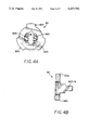
- FIGS. 4A-B are end and side views of the retaining plate for use in the computer equipment lock of the present invention.
- FIG. 5 is an isolated perspective view of a locking spindle for use in the computer equipment lock of the present invention.
- FIGS. 6A-B are front and rear views of a stationary tumbler sleeve for use in the computer equipment lock of the present invention.
- FIGS. 7A-B are front and rear views of a rotatable driver sleeve for use in the computer equipment lock of the present invention.
- FIGS. 1-3 a tubular lock 10 according to the preferred embodiment of the present invention is shown generally in FIG. 1, in exploded view in FIG. 2, and in cross section in FIG. 3.
- the lock 10 includes an outer shell having a forward portion 15 and a rear portion 20.
- a non-rotatable inner shell 22 housed within the outer shell is a non-rotatable inner shell 22 as best seen by reference to FIG. 2.
- Telescoped within the inner shell 22 is a rotatable driver sleeve 24. In the assembled state, the rotatable driver sleeve 24 is disposed in face to face relation with non-rotatable tumbler sleeve 26.
- the rotatable driver sleeve 24 houses a multiplicity of driver pins 28 which cooperatively depress spring biased tumbler pins 30 housed within the non-rotatable tumbler sleeve 26 upon insertion of a proper key member 32 (FIG. 2), thereby permitting relative rotation of driver sleeve 24.
- Extending through sleeves 24, 26 is a locking spindle 34, described in greater detail below.
- connecting means 36 are disposed between rotatable driver sleeve 24 and locking spindle 34, thereby serving to transmit the rotational movement of driver sleeve 24 to the spindle 34.
- the forward portion 15 of the outer shell comprises a cable ring structure as shown most clearly in FIGS. 2 and 3.
- the cable ring structure comprises a substantially circular body portion 38 and an integrally formed stem portion 40.
- the stem portion 40 is provided with a substantially hollow center portion 42 which may receive cable means 44.
- the preferred embodiment of the cable means for use in the present invention includes an internal core 46 formed from stainless steel aircraft cable and an external sleeve 48 formed from PVC or a like material.
- the internal core includes a proximal end portion 50 which extends beyond the end of the sleeve 48.
- the proximal end portion 50 of the cable core 46 is receivable within the hollow center portion 42 of the outer shell stem 40.
- the distal end of the cable 44 is formed into a loop 52 in a manner well known to those skilled in the art.
- the loop 52 may be either connected to a stationary body by means o#a second locking device (not shown) or passed over the rear end 20 of the tubular lock prior to insertion of the spindle into an appropriate locking port, thereby creating a locked circuit between the tubular lock 10 and the attached cable means 44.
- PVC sleeve 48 to cover the cable means 46 permits the cable means to be wrapped around stationary objects prior to the loop 52 being disposed over the lock 10 of the present invention without damaging the surface of the stationary object.
- the rear portion 20 of the outer shell is provided with a rear surface 54 of a stepped configuration.
- the rear surface 54 is comprised of a substantially planar section 56 having a lowered shoulder member 58 at the perimeter of the outer shell and a raised shoulder member 60 at the interior thereof.
- a scuff plate 62 will be attached to the rear surface 54 of the outer shell 20.
- the scuff plate 62 is secured in place by adhesive means as are well known to those skilled in the art as well as by geometric cooperation with shoulder members 58, 60 of rear surface 54.
- an inner shell 22 Disposed within the outer shell portions 15, 20 is an inner shell 22 which is shown most clearly in FIG. 2. As shown, the forward face of the inner shell 22 has a substantially circular perimeter with indent means 64 for properly aligning and guiding key 32 into contacting relation with driver pins 28.
- the body portion 66 of the inner shell 22 is of a substantially solid cylindrical configuration. As shown, a bore hole 68 and a slot 70 are disposed within inner shell 22 for respectively accepting a first retaining pin 72 and a second retaining pin 74.
- retaining pin 72 is disposed between inner shell 22 and non-rotatable tumbler sleeve 26 while retaining pin 74 is disposed between the outer shell 20 and slot 70 housed within inner shell 22.
- this attachment permits the rear portion 20 of the outer shell to slide with relation to inner shell 22 and spindle 34.
- the spindle 34 will comprise a head portion 76, a neck portion 77 and a body portion 78.
- the spindle head 76 and neck 77 will preferably form a T-shaped cross section.
- the T-shaped spindle will be inserted into a slot provided in a computer or other portable device to be secured (not shown).
- the geometry of the slot should be such that the head 76 of spindle 34 may be inserted or withdrawn only when the spindle and slot are properly aligned.
- the rotatable driver sleeve 24 and connected spindle 34 will then be rotated approximately 90° in the manner described below, thereby preventing the withdrawal of the lock 10 through the application of an axial force.
- a retaining plate 80 which is illustrated in FIGS. 2, 4A and 4b.
- Retaining plate 80 includes a slotted passage 81 through which spindle head 76 may pass when the spindle 34 and retaining plate 80 are properly aligned.
- the retaining plate 80 also preferably includes extensive members 82a, 82b which will extend rearwardly along spindle neck 78 after insertion of spindle head 76 through passage 81.
- the retaining plate 80 must be well secured against rotation within the lock 10. In a preferred embodiment of the present invention, this securement is achieved by means of the cooperative geometric engagement between peripheral segments 83a-83c and the matching spline detail of inner shell 22.
- internally disposed spring means 85 serve to bias rear portion 20 of the outer shell towards the spindle head 76, thereby reducing the gap between rear scuff plate 62 and the slot provided in the computer or other device, thereby substantially covering the anti-rotation arms 82a, 82b and reducing the potential for lock manipulation and damage.
- the internally disposed spring means 85 also provide axial force directed against retaining plate 80, thereby providing added stability to the overall lock structure.
- the spindle for use in the lock of the present invention is shown in FIG. 5.
- the spindle is substantially "T" shaped and includes a substantially cylindrical body portion 78 and a substantially cylindrical neck portion 77 having a diameter which is less than that of the body portion 78.
- head portion 76 is disposed at the end of neck portion 77 to form a T-shaped member for insertion into a geometrically similar slotted port on the portable computer or other device to be secured.
- the largest cross sectional dimension of the spindle head 76 will slightly exceed the diameter of the body portion 78, thus precluding withdrawal of the spindle through driver sleeve 24.
- the smallest cross sectional dimension of the spindle head will preferably be substantially equivalent to the diameter of the neck portion 77.
- FIGS. 6A and 6B showing, respectively, forward and rear views of the non-rotatable tumbler sleeve 26.
- the inner surface of the tumbler sleeve 26 is provided with support surfaces 90, 91 which are maintained in contacting relation with the outer surface of body portion 78 of spindle 34.
- the inner surface of the tumbler sleeve is also provided with indentures 92, 93 which permit spindle head 76 to pass through the tumbler sleeve 26 when the proper respective alignment between these components is achieved.
- the non-rotatable tumbler sleeve thus provides a stable support for the spindle 34 while at the same time permitting passage of the spindle head 76 during the assembly process.
- the spindle 34 is provided with a gradual transition zone 94 (FIG. 3) located between neck 77 and body portion 78.
- a gradual transition zone 94 FIG. 3
- the use of such a rounded transition zone reduces the potential for spindle failure since the forces applied to the spindle are distributed across a broad surface, thus avoiding the concentration of forces at one location.
- spindles utilized in the past have often incorporated sharp-edged transition zones, leading to the potential for catastrophic failure at high energy surfaces such as corners and the like.
- FIGS. 7A and 7B The forward and rear faces of rotatable driver sleeve 24 are illustrated in FIGS. 7A and 7B respectively.
- the driver sleeve is provided with internally disposed detent means 96 extending into the central portion thereof.
- the body portion 78 of spindle 34 is provided with a groove 98 extending from the forward face 100 of the spindle to a point 102 lying forward of the neck portion 77.
- groove 98 cooperatively engages the detent means 96 of the driver sleeve 24. Accordingly, when the spindle 34 and the driver sleeve 24 are in engagement, relative axial movement is restricted by the length of the groove 98.
- the groove 98 in spindle 34 is of a substantially uniform depth over its entire length except for a depressed bore 104.
- the driver sleeve 24 and the spindle 34 are attached by connecting pin 36 illustrated in FIGS. 2 and 3.
- This connecting pin 36 is inserted through the driver sleeve bore hole 106 and into depressed bore 104 located in groove 98.
- the placement of depressed bore 104 within groove 98 enhances the ease of assembly since proper radial alignment between the driver sleeve 24 and spindle 34 is readily achieved through engagement of the detent means 96 with groove 98.
- driver sleeve bore hole 106 and spindle bore hole 104 will be properly aligned when the detent 96 of the driver sleeve comes into abutting relation with the terminal point 102 of groove 98, thus substantially simplifying the insertion of connecting pin 36.
- Ease of assembly in the lock 10 of the present invention is further enhanced by the use of slotted pin engagement means 108 on the outer surface of non-rotatable tumbler sleeve 26. As illustrated in FIGS. 2 and 3, rotation of tumbler sleeve 26 is prohibited by means of a retaining pin 72 and engaging slot 108. As will be appreciated, the use of slot 108 rather than a bore hole enhances the ease of assembly as well as simplifying the manufacturing process, since the need to achieve close tolerances between the inner shell 22 and the tumbler sleeve 26 of each individual lock is substantially reduced.
- a series of angularly spaced tumbler pins 30 are slidably positioned within bores 110 defined through the non-rotatable tumbler sleeve 26 (FIG. 6A) and function to normally retain the spindle 34 in its locked position wherein rotational movement is prohibited.
- the tumbler pins 30 are invariably urged forward by means of coiled compression springs 112. These coiled compression springs are disposed within the bores 110 which retain the tumbler pins. Under the urging of the springs 112, the tumbler pins 30 are disposed along the bores 110 in such a manner that the outer ends of the pins normally project outward beyond the shear plane 114 (FIG.
Abstract
Description
Claims (7)
Priority Applications (1)
| Application Number | Priority Date | Filing Date | Title |
|---|---|---|---|
| US08/119,314 US5327752A (en) | 1992-06-01 | 1993-09-09 | Computer equipment lock |
Applications Claiming Priority (2)
| Application Number | Priority Date | Filing Date | Title |
|---|---|---|---|
| US89178392A | 1992-06-01 | 1992-06-01 | |
| US08/119,314 US5327752A (en) | 1992-06-01 | 1993-09-09 | Computer equipment lock |
Related Parent Applications (1)
| Application Number | Title | Priority Date | Filing Date |
|---|---|---|---|
| US89178392A Continuation | 1992-06-01 | 1992-06-01 |
Publications (1)
| Publication Number | Publication Date |
|---|---|
| US5327752A true US5327752A (en) | 1994-07-12 |
Family
ID=25398813
Family Applications (1)
| Application Number | Title | Priority Date | Filing Date |
|---|---|---|---|
| US08/119,314 Expired - Lifetime US5327752A (en) | 1992-06-01 | 1993-09-09 | Computer equipment lock |
Country Status (1)
| Country | Link |
|---|---|
| US (1) | US5327752A (en) |
Cited By (100)
| Publication number | Priority date | Publication date | Assignee | Title |
|---|---|---|---|---|
| US5381685A (en) * | 1992-01-24 | 1995-01-17 | Kensington Microware Limited | Computer physical security device |
| US5400629A (en) * | 1992-06-01 | 1995-03-28 | Fort Lock Corporation | Axial pin tumbler lock |
| US5493878A (en) * | 1992-01-24 | 1996-02-27 | Kensington Microware Limited | Computer physical security device |
| US5595074A (en) * | 1996-01-29 | 1997-01-21 | Munro; Robert G. | Desktop security locking station for a laptop computer or similarly sized computer peripheral |
| US5622064A (en) * | 1995-05-24 | 1997-04-22 | Dell Usa, L.P. | Computer access port locking device and method |
| US5687592A (en) * | 1993-07-23 | 1997-11-18 | Dell Usa, L.P. | Mechanical lock for a removable hard disk drive and a removable memory card |
| EP0808402A1 (en) * | 1995-02-08 | 1997-11-26 | Kensington Microware Limited | Computer physical security device |
| US5692400A (en) * | 1996-03-25 | 1997-12-02 | Hewlett-Packard Company | Securing portable computers and associated docking systems |
| US5709110A (en) * | 1996-10-07 | 1998-01-20 | Greenfield; Jack | Security system for a lap-top computer |
| US5791171A (en) * | 1997-02-12 | 1998-08-11 | Qualtec Data Products, Inc. | Scissor lock with removable cable adapter |
| WO1998039541A1 (en) | 1997-03-07 | 1998-09-11 | Qualtec Data Products, Inc. | Lock with removable cable adapter |
| US5832754A (en) * | 1995-04-05 | 1998-11-10 | Mckenzie; Dennis | Locking device for surfboards |
| US5868014A (en) * | 1995-12-23 | 1999-02-09 | Samsung Electronics Co., Ltd. | Security locking device for a desk top computer |
| US5913907A (en) * | 1998-04-30 | 1999-06-22 | Lee; Miko | Lock for securing a portable computer or the like |
| US5983679A (en) * | 1998-11-17 | 1999-11-16 | Micro Security Devices, Inc. | Portable anti-theft locking anchor |
| US5987937A (en) * | 1997-10-22 | 1999-11-23 | Samsung Electronics Co., Ltd. | Peripheral locking device for portable computers |
| US6000252A (en) | 1992-01-24 | 1999-12-14 | Acco Brands, Inc. | Computer physical security device |
| US6038891A (en) * | 1997-03-27 | 2000-03-21 | Acco Brands, Inc. | Security hole fastening device |
| US6112562A (en) * | 1993-01-19 | 2000-09-05 | Acco Brands, Inc. | Computer physical security device |
| US6112561A (en) | 1994-08-26 | 2000-09-05 | Acco Brands, Inc. | Security device for a portable computer |
| DE19915959A1 (en) * | 1999-04-09 | 2000-11-02 | Jin Tay Ind Co | Lock for physically attaching a computer to an object, where the lock is of straightforward design having only one moving part, an interlock plate with extending locking journal |
| US6170304B1 (en) * | 1999-02-26 | 2001-01-09 | Hewlett-Packard Company | Method and apparatus for securing electronic components |
| US6173591B1 (en) * | 1996-07-15 | 2001-01-16 | Acco Brands, Inc. | Security hole fastening device |
| US6199413B1 (en) | 1999-09-23 | 2001-03-13 | Kryptonite Corporation | Security lock for portable articles |
| US6205824B1 (en) * | 2000-01-31 | 2001-03-27 | Jin Tay Industries Co Ltd | Lock with a fastening cable |
| US6212918B1 (en) | 1998-09-24 | 2001-04-10 | Benson Enterprises Incorporated | Locking mechanism for portable valuables |
| US6227017B1 (en) * | 1994-04-12 | 2001-05-08 | Darrell A. Igelmund | Computer slot security adaptor |
| US6257029B1 (en) * | 2000-01-05 | 2001-07-10 | Ming-Pang Liao | Computer lock having double locking leaves |
| US20020017119A1 (en) * | 1992-01-24 | 2002-02-14 | Acco Brands, Inc. | Computer physical security device |
| US6360405B1 (en) * | 1999-06-21 | 2002-03-26 | Kryptonite Corporation | Security anchor/tether assemblage for portable articles |
| WO2002042586A1 (en) | 2000-11-23 | 2002-05-30 | Mair Avganim | Locking device for portable computers |
| US6401502B1 (en) * | 2001-05-08 | 2002-06-11 | Jin Tay Industries Co., Ltd. | Multipurpose cable lock |
| US6463770B1 (en) * | 2001-07-03 | 2002-10-15 | Miko Lee | Lock for a computer |
| EP1028212A3 (en) * | 1994-11-15 | 2002-12-18 | Acco Brands Inc. | Computer physical security device |
| US6513350B1 (en) * | 2000-09-20 | 2003-02-04 | Acco Brands, Inc. | Computer physical security device |
| WO2003046320A1 (en) * | 2001-11-26 | 2003-06-05 | Mair Avganim | Anti-theft device for portable computers |
| US6578394B2 (en) | 2001-09-06 | 2003-06-17 | Hewlett-Packard Development Company | Portable computer security device |
| US6601416B1 (en) * | 2002-04-10 | 2003-08-05 | Richard Sanders | Notebook computer security lever locking assembly |
| US6619081B1 (en) * | 2001-12-31 | 2003-09-16 | Chun Te Yu | Steel cable lock structure |
| US6619080B1 (en) * | 2001-12-31 | 2003-09-16 | Chun Te Yu | Lock bolt structure of steel cable lock |
| US6662602B1 (en) | 1996-11-08 | 2003-12-16 | Acco Brands, Inc. | Security device for a portable computer |
| US6735990B1 (en) | 1992-01-24 | 2004-05-18 | Acco Brands, Inc. | Computer physical security device |
| US6742366B1 (en) | 2002-12-23 | 2004-06-01 | The Sun Lock Company Ltd. | Locking and securing system for slot bearing products |
| US6755056B2 (en) * | 1994-04-12 | 2004-06-29 | Darrell A. Igelmund | Computer slot security adaptor |
| US6758069B2 (en) * | 2002-08-30 | 2004-07-06 | Acco Brands, Inc. | Computer physical security devices |
| WO2004067887A1 (en) * | 2003-01-30 | 2004-08-12 | Mair Avganim | An arrangement for arresting a portable object to a stationary object by a cable |
| US6779370B2 (en) | 2002-02-27 | 2004-08-24 | Belkin Components | Security device, method of manufacturing the same, and method of operating the same |
| US20050268675A1 (en) * | 2004-04-22 | 2005-12-08 | Loudon Alexander J T | Computer & electronics security system |
| US20060081021A1 (en) * | 2004-10-20 | 2006-04-20 | Acco Brands, Inc. | Security device including linearly moving member |
| US20060082965A1 (en) * | 2004-10-20 | 2006-04-20 | Paul Walker | Securing computer equipment |
| US20060138915A1 (en) * | 2004-12-28 | 2006-06-29 | Goldberg Mark A | Mobile computer security cabinet |
| US7073358B1 (en) * | 2005-12-22 | 2006-07-11 | Grace Lin | Self-locking cable lock |
| US7079032B2 (en) | 2003-03-27 | 2006-07-18 | Acco Brands Usa Llc | Portable electronic device physical security apparatus with alarmed cable |
| US7150168B1 (en) * | 2005-10-17 | 2006-12-19 | Lambert Kuo | Tubular pin tumbler lock unit |
| US7152440B1 (en) | 2001-10-09 | 2006-12-26 | Infocus Corporation | Apparatus to secure an access door on a housing |
| US7185518B1 (en) * | 2005-10-07 | 2007-03-06 | Ho E Screw & Hardware Co., Ltd. | Safety lock for computer |
| US20070074547A1 (en) * | 2005-09-30 | 2007-04-05 | Accton Technology Corporation | Lock structure for coupling kensington lock |
| US20070125137A1 (en) * | 2005-12-01 | 2007-06-07 | Compucage International Inc. | Security device for a computer system |
| US20070139874A1 (en) * | 2005-12-15 | 2007-06-21 | Eiichi Tanaka | Detachable handle for notebook computers |
| US20070226967A1 (en) * | 2006-04-01 | 2007-10-04 | Wine-Woods Enterprises | Locking snap buckle |
| GB2437108A (en) * | 2006-04-06 | 2007-10-17 | Tag Company | Security device for a computer |
| US20070295040A1 (en) * | 2006-06-23 | 2007-12-27 | Miko Lee | Merchandise lock |
| US20080034817A1 (en) * | 2006-08-09 | 2008-02-14 | Asustek Computer Inc. | Lock module |
| US20080053168A1 (en) * | 2006-09-05 | 2008-03-06 | Miz Engineering Ltd. | Lock assembly |
| US20080054127A1 (en) * | 2006-09-05 | 2008-03-06 | Se-Kure Controls, Inc. | System for securing a cable to a portable article |
| US20080072633A1 (en) * | 2006-09-25 | 2008-03-27 | Elsamma Samuel | Security device |
| WO2008051927A2 (en) * | 2006-10-23 | 2008-05-02 | Acco Brands Usa Llc | Security apparatus |
| US20080110217A1 (en) * | 2006-11-14 | 2008-05-15 | Targus Group International, Inc. | Security System and Related Devices and Methods |
| US20080116327A1 (en) * | 2006-11-22 | 2008-05-22 | Goldberg Mark A | Mobile workstation |
| US20080142660A1 (en) * | 2006-12-18 | 2008-06-19 | Goldberg Mark A | Wall mounted workstation |
| US20080164792A1 (en) * | 2007-01-04 | 2008-07-10 | Goldberg Mark A | Mobile computer security cart |
| US7415852B1 (en) * | 2004-10-06 | 2008-08-26 | Acco Brands Usa Llc | Tubular lock with theft deterrent |
| US7507096B1 (en) | 2004-10-08 | 2009-03-24 | Maxtor Corporation | Data storage device security system |
| WO2007061568A3 (en) * | 2005-11-18 | 2009-04-30 | Acco Brands Usa Llc | Locking device with passage |
| US20090188287A1 (en) * | 2008-01-30 | 2009-07-30 | Forrest Xu | Axial spring balancing pin tumbler lock |
| US7647796B2 (en) | 2003-07-23 | 2010-01-19 | Acco Brands Usa Llc | Computer physical security device with retractable cable |
| US20100309853A1 (en) * | 2006-10-26 | 2010-12-09 | Qualcomm Incorporated | Progressive information beacon symbols |
| US20110007475A1 (en) * | 2009-07-10 | 2011-01-13 | Eduardo Escamilla | Information Handling System Flexible Security Lock |
| US20110016932A1 (en) * | 2008-02-15 | 2011-01-27 | Sinox Co., Ltd | Burgarproof lock and burgarproof system using the same |
| US7891220B2 (en) | 2006-01-05 | 2011-02-22 | Sinox Company Ltd. | Multi-purpose detachable lock container and method of use |
| US20110179834A1 (en) * | 2010-01-25 | 2011-07-28 | ACCO Brands Corporation | Security apparatus including breakaway key |
| US7997106B2 (en) | 2009-05-29 | 2011-08-16 | Acco Brands Usa Llc | Security apparatus including locking head and attachment device |
| US20110209311A1 (en) * | 2006-04-01 | 2011-09-01 | Woods Michael E | Security system and method including security buckle |
| USD651889S1 (en) * | 2011-04-19 | 2012-01-10 | Acco Brands Usa Llc | Security apparatus |
| US20120167647A1 (en) * | 2010-12-29 | 2012-07-05 | Chang-Chiang Yu | Lock structure for electronic device |
| US8230707B2 (en) | 2007-05-25 | 2012-07-31 | ACCO Brands Corporation | Security system with lock interface member with multiple apertures |
| US20120227448A1 (en) * | 2011-03-07 | 2012-09-13 | Ingamar Co., Ltd. | Rotatable lock for a portable electronic device |
| USD667286S1 (en) * | 2011-08-04 | 2012-09-18 | Sinox Co., Ltd. | Lock |
| US8353184B2 (en) | 2005-01-21 | 2013-01-15 | Sinox Company Ltd. | Tamper indicating padlock |
| USD674266S1 (en) | 2003-08-05 | 2013-01-15 | The Eastern Company | Cable shackle padlock having a sidewall aperture for a status indicator |
| US8671721B2 (en) | 2010-07-06 | 2014-03-18 | Sinox Company Ltd. | Lock structure |
| US8695384B2 (en) | 2010-07-06 | 2014-04-15 | Sinox Company Ltd. | Lock structure |
| US8720236B2 (en) | 2003-05-14 | 2014-05-13 | Sinox Company Ltd. | Padlock |
| US8881558B2 (en) | 2003-08-05 | 2014-11-11 | The Eastern Company | Combination and key operated locks with indicators |
| US8922994B2 (en) | 2012-09-21 | 2014-12-30 | Lenovo (Singapore) Ltd. Pte. | Locking mechanism |
| US20180238083A1 (en) * | 2017-02-20 | 2018-08-23 | Ingenico Group | Locking bracket for locking a digital device into a casing |
| US10337212B2 (en) * | 2015-06-04 | 2019-07-02 | Zeal Innovation Ltd | Security devices |
| US20190210509A1 (en) * | 2018-01-09 | 2019-07-11 | Ford Global Technologies, Llc | Truck Box Cable Lock Assembly |
| US10360161B2 (en) | 2017-03-29 | 2019-07-23 | International Business Machines Corporation | Cable lock with confidential data protection |
| USD916152S1 (en) * | 2020-08-24 | 2021-04-13 | Apq Development, Llc | Compression limiter |
Citations (7)
| Publication number | Priority date | Publication date | Assignee | Title |
|---|---|---|---|---|
| US3785183A (en) * | 1972-01-31 | 1974-01-15 | I O Prague Corp | Theft deterrent for office machines, television sets and small factory tools |
| GB1376011A (en) * | 1972-01-24 | 1974-12-04 | Keystone Consolidated Ind Inc | Cylinder lock |
| US3859826A (en) * | 1973-02-21 | 1975-01-14 | M Leonard Singer | Apparatus for securing office equipment at a remote station |
| US4057984A (en) * | 1975-11-24 | 1977-11-15 | Avaiusini Mauricio V | Ski lock device with single actuating means |
| US4858455A (en) * | 1988-02-11 | 1989-08-22 | Ming Tay Hardware Ind. Co., Ltd. | Lock core |
| US4938040A (en) * | 1990-01-12 | 1990-07-03 | Humphreys Jr William J | Securing device for surfboards |
| US5024072A (en) * | 1990-08-28 | 1991-06-18 | Miko Lee | Tumbler pin lock system |
-
1993
- 1993-09-09 US US08/119,314 patent/US5327752A/en not_active Expired - Lifetime
Patent Citations (7)
| Publication number | Priority date | Publication date | Assignee | Title |
|---|---|---|---|---|
| GB1376011A (en) * | 1972-01-24 | 1974-12-04 | Keystone Consolidated Ind Inc | Cylinder lock |
| US3785183A (en) * | 1972-01-31 | 1974-01-15 | I O Prague Corp | Theft deterrent for office machines, television sets and small factory tools |
| US3859826A (en) * | 1973-02-21 | 1975-01-14 | M Leonard Singer | Apparatus for securing office equipment at a remote station |
| US4057984A (en) * | 1975-11-24 | 1977-11-15 | Avaiusini Mauricio V | Ski lock device with single actuating means |
| US4858455A (en) * | 1988-02-11 | 1989-08-22 | Ming Tay Hardware Ind. Co., Ltd. | Lock core |
| US4938040A (en) * | 1990-01-12 | 1990-07-03 | Humphreys Jr William J | Securing device for surfboards |
| US5024072A (en) * | 1990-08-28 | 1991-06-18 | Miko Lee | Tumbler pin lock system |
Cited By (160)
| Publication number | Priority date | Publication date | Assignee | Title |
|---|---|---|---|---|
| US6553794B1 (en) | 1992-01-24 | 2003-04-29 | Acco Brands, Inc. | Computer physical security device |
| US6000252A (en) | 1992-01-24 | 1999-12-14 | Acco Brands, Inc. | Computer physical security device |
| US6000251A (en) | 1992-01-24 | 1999-12-14 | Acco Brands, Inc. | Computer physical security device |
| US5502989A (en) * | 1992-01-24 | 1996-04-02 | Kensington Microware Limited | Computer physical security device |
| US6588241B1 (en) | 1992-01-24 | 2003-07-08 | Acco Brands, Inc. | Computer physical security device |
| US6735990B1 (en) | 1992-01-24 | 2004-05-18 | Acco Brands, Inc. | Computer physical security device |
| US7121125B2 (en) | 1992-01-24 | 2006-10-17 | Acco Brands Usa Llc | Computer physical security device |
| US6155088A (en) | 1992-01-24 | 2000-12-05 | Acco Brands, Inc. | Computer physical security device |
| US5493878A (en) * | 1992-01-24 | 1996-02-27 | Kensington Microware Limited | Computer physical security device |
| US20010013234A1 (en) * | 1992-01-24 | 2001-08-16 | William R. Murray | Computer physical security device |
| US5381685A (en) * | 1992-01-24 | 1995-01-17 | Kensington Microware Limited | Computer physical security device |
| US7143614B1 (en) * | 1992-01-24 | 2006-12-05 | Acco Brands Usa Llc | Computer physical security device |
| US20020017119A1 (en) * | 1992-01-24 | 2002-02-14 | Acco Brands, Inc. | Computer physical security device |
| US5400629A (en) * | 1992-06-01 | 1995-03-28 | Fort Lock Corporation | Axial pin tumbler lock |
| US6112562A (en) * | 1993-01-19 | 2000-09-05 | Acco Brands, Inc. | Computer physical security device |
| US5687592A (en) * | 1993-07-23 | 1997-11-18 | Dell Usa, L.P. | Mechanical lock for a removable hard disk drive and a removable memory card |
| US6305199B1 (en) | 1994-04-12 | 2001-10-23 | Darrell A. Igelmund | Computer slot security adaptor |
| US6227017B1 (en) * | 1994-04-12 | 2001-05-08 | Darrell A. Igelmund | Computer slot security adaptor |
| US6755056B2 (en) * | 1994-04-12 | 2004-06-29 | Darrell A. Igelmund | Computer slot security adaptor |
| US6112561A (en) | 1994-08-26 | 2000-09-05 | Acco Brands, Inc. | Security device for a portable computer |
| EP1028212A3 (en) * | 1994-11-15 | 2002-12-18 | Acco Brands Inc. | Computer physical security device |
| US6006557A (en) | 1995-02-08 | 1999-12-28 | Acco Brands, Inc. | Computer physical security device |
| EP0808402A1 (en) * | 1995-02-08 | 1997-11-26 | Kensington Microware Limited | Computer physical security device |
| EP0808402A4 (en) * | 1995-02-08 | 1998-04-08 | Kensington Microwave Ltd | Computer physical security device |
| US5832754A (en) * | 1995-04-05 | 1998-11-10 | Mckenzie; Dennis | Locking device for surfboards |
| US5622064A (en) * | 1995-05-24 | 1997-04-22 | Dell Usa, L.P. | Computer access port locking device and method |
| US5868014A (en) * | 1995-12-23 | 1999-02-09 | Samsung Electronics Co., Ltd. | Security locking device for a desk top computer |
| US5595074A (en) * | 1996-01-29 | 1997-01-21 | Munro; Robert G. | Desktop security locking station for a laptop computer or similarly sized computer peripheral |
| US6047572A (en) * | 1996-03-25 | 2000-04-11 | Hewlett-Packard Company | Docking station with multi-function security feature |
| US5692400A (en) * | 1996-03-25 | 1997-12-02 | Hewlett-Packard Company | Securing portable computers and associated docking systems |
| US6173591B1 (en) * | 1996-07-15 | 2001-01-16 | Acco Brands, Inc. | Security hole fastening device |
| US6301940B1 (en) * | 1996-07-15 | 2001-10-16 | Acco Brands, Inc. | Security hole fastening device |
| US5709110A (en) * | 1996-10-07 | 1998-01-20 | Greenfield; Jack | Security system for a lap-top computer |
| US6662602B1 (en) | 1996-11-08 | 2003-12-16 | Acco Brands, Inc. | Security device for a portable computer |
| US5791171A (en) * | 1997-02-12 | 1998-08-11 | Qualtec Data Products, Inc. | Scissor lock with removable cable adapter |
| US5875657A (en) * | 1997-03-07 | 1999-03-02 | Qualtec Data Products, Inc. | Lock with removable cable adapter |
| WO1998039541A1 (en) | 1997-03-07 | 1998-09-11 | Qualtec Data Products, Inc. | Lock with removable cable adapter |
| US6038891A (en) * | 1997-03-27 | 2000-03-21 | Acco Brands, Inc. | Security hole fastening device |
| US5987937A (en) * | 1997-10-22 | 1999-11-23 | Samsung Electronics Co., Ltd. | Peripheral locking device for portable computers |
| US5913907A (en) * | 1998-04-30 | 1999-06-22 | Lee; Miko | Lock for securing a portable computer or the like |
| US6212918B1 (en) | 1998-09-24 | 2001-04-10 | Benson Enterprises Incorporated | Locking mechanism for portable valuables |
| US5983679A (en) * | 1998-11-17 | 1999-11-16 | Micro Security Devices, Inc. | Portable anti-theft locking anchor |
| US6321579B1 (en) | 1998-11-17 | 2001-11-27 | Micro Security Devices Inc. | Portable anti-theft locking anchor |
| US6170304B1 (en) * | 1999-02-26 | 2001-01-09 | Hewlett-Packard Company | Method and apparatus for securing electronic components |
| DE19915959C2 (en) * | 1999-04-09 | 2001-03-01 | Jin Tay Ind Co | Lock for securing a computer to an object |
| DE19915959A1 (en) * | 1999-04-09 | 2000-11-02 | Jin Tay Ind Co | Lock for physically attaching a computer to an object, where the lock is of straightforward design having only one moving part, an interlock plate with extending locking journal |
| US6360405B1 (en) * | 1999-06-21 | 2002-03-26 | Kryptonite Corporation | Security anchor/tether assemblage for portable articles |
| US6199413B1 (en) | 1999-09-23 | 2001-03-13 | Kryptonite Corporation | Security lock for portable articles |
| US6257029B1 (en) * | 2000-01-05 | 2001-07-10 | Ming-Pang Liao | Computer lock having double locking leaves |
| US6205824B1 (en) * | 2000-01-31 | 2001-03-27 | Jin Tay Industries Co Ltd | Lock with a fastening cable |
| US6513350B1 (en) * | 2000-09-20 | 2003-02-04 | Acco Brands, Inc. | Computer physical security device |
| EP1328696A1 (en) * | 2000-09-20 | 2003-07-23 | ACCO Brands, Inc. | Computer physical security device |
| EP1328696A4 (en) * | 2000-09-20 | 2004-04-14 | Acco Brands Inc | Computer physical security device |
| WO2002042586A1 (en) | 2000-11-23 | 2002-05-30 | Mair Avganim | Locking device for portable computers |
| US6401502B1 (en) * | 2001-05-08 | 2002-06-11 | Jin Tay Industries Co., Ltd. | Multipurpose cable lock |
| US6463770B1 (en) * | 2001-07-03 | 2002-10-15 | Miko Lee | Lock for a computer |
| US6578394B2 (en) | 2001-09-06 | 2003-06-17 | Hewlett-Packard Development Company | Portable computer security device |
| US7152440B1 (en) | 2001-10-09 | 2006-12-26 | Infocus Corporation | Apparatus to secure an access door on a housing |
| US20040261473A1 (en) * | 2001-11-26 | 2004-12-30 | Mair Avganim | Anti -theft device for portable computers |
| WO2003046320A1 (en) * | 2001-11-26 | 2003-06-05 | Mair Avganim | Anti-theft device for portable computers |
| US7028513B2 (en) | 2001-11-26 | 2006-04-18 | Mair Avganim | Anti-theft device for portable computers |
| US6619080B1 (en) * | 2001-12-31 | 2003-09-16 | Chun Te Yu | Lock bolt structure of steel cable lock |
| US6619081B1 (en) * | 2001-12-31 | 2003-09-16 | Chun Te Yu | Steel cable lock structure |
| US6779370B2 (en) | 2002-02-27 | 2004-08-24 | Belkin Components | Security device, method of manufacturing the same, and method of operating the same |
| US20050022566A1 (en) * | 2002-02-27 | 2005-02-03 | Bellow Stephen Lester | Security device, method of manufacturing the same, and method of operating the same |
| US6971254B2 (en) | 2002-02-27 | 2005-12-06 | Belkin Components | Security device, method of manufacturing the same, and method of operating the same |
| US6601416B1 (en) * | 2002-04-10 | 2003-08-05 | Richard Sanders | Notebook computer security lever locking assembly |
| US6758069B2 (en) * | 2002-08-30 | 2004-07-06 | Acco Brands, Inc. | Computer physical security devices |
| US6742366B1 (en) | 2002-12-23 | 2004-06-01 | The Sun Lock Company Ltd. | Locking and securing system for slot bearing products |
| WO2004067887A1 (en) * | 2003-01-30 | 2004-08-12 | Mair Avganim | An arrangement for arresting a portable object to a stationary object by a cable |
| US20060225470A1 (en) * | 2003-01-30 | 2006-10-12 | Mair Avganim | Arrangement for arresting a portable object to a stationary object by a cable |
| US7441426B2 (en) | 2003-01-30 | 2008-10-28 | Mair Avganim | Arrangement for arresting a portable object to a stationary object by a cable |
| US7079032B2 (en) | 2003-03-27 | 2006-07-18 | Acco Brands Usa Llc | Portable electronic device physical security apparatus with alarmed cable |
| US8720236B2 (en) | 2003-05-14 | 2014-05-13 | Sinox Company Ltd. | Padlock |
| US7647796B2 (en) | 2003-07-23 | 2010-01-19 | Acco Brands Usa Llc | Computer physical security device with retractable cable |
| USD674266S1 (en) | 2003-08-05 | 2013-01-15 | The Eastern Company | Cable shackle padlock having a sidewall aperture for a status indicator |
| US8881558B2 (en) | 2003-08-05 | 2014-11-11 | The Eastern Company | Combination and key operated locks with indicators |
| US20050268675A1 (en) * | 2004-04-22 | 2005-12-08 | Loudon Alexander J T | Computer & electronics security system |
| US7415852B1 (en) * | 2004-10-06 | 2008-08-26 | Acco Brands Usa Llc | Tubular lock with theft deterrent |
| US7507096B1 (en) | 2004-10-08 | 2009-03-24 | Maxtor Corporation | Data storage device security system |
| US20060082965A1 (en) * | 2004-10-20 | 2006-04-20 | Paul Walker | Securing computer equipment |
| US20060081021A1 (en) * | 2004-10-20 | 2006-04-20 | Acco Brands, Inc. | Security device including linearly moving member |
| US7227747B2 (en) | 2004-10-20 | 2007-06-05 | Hewlett-Packard Development Company, L.P. | Securing computer equipment |
| US20060138915A1 (en) * | 2004-12-28 | 2006-06-29 | Goldberg Mark A | Mobile computer security cabinet |
| US8353184B2 (en) | 2005-01-21 | 2013-01-15 | Sinox Company Ltd. | Tamper indicating padlock |
| US20070074547A1 (en) * | 2005-09-30 | 2007-04-05 | Accton Technology Corporation | Lock structure for coupling kensington lock |
| US7185518B1 (en) * | 2005-10-07 | 2007-03-06 | Ho E Screw & Hardware Co., Ltd. | Safety lock for computer |
| US7150168B1 (en) * | 2005-10-17 | 2006-12-19 | Lambert Kuo | Tubular pin tumbler lock unit |
| US7730751B2 (en) | 2005-11-18 | 2010-06-08 | Acco Brands Usa Llc | Locking device with passage |
| US7963132B2 (en) * | 2005-11-18 | 2011-06-21 | Acco Brands Usa Llc | Locking device with passage |
| US20100263414A1 (en) * | 2005-11-18 | 2010-10-21 | Guillermo Andres | Locking device with passage |
| WO2007061568A3 (en) * | 2005-11-18 | 2009-04-30 | Acco Brands Usa Llc | Locking device with passage |
| TWI392789B (en) * | 2005-11-18 | 2013-04-11 | Acco Brands Usa Llc | Locking device with passage |
| US20070125137A1 (en) * | 2005-12-01 | 2007-06-07 | Compucage International Inc. | Security device for a computer system |
| US20070139874A1 (en) * | 2005-12-15 | 2007-06-21 | Eiichi Tanaka | Detachable handle for notebook computers |
| US7073358B1 (en) * | 2005-12-22 | 2006-07-11 | Grace Lin | Self-locking cable lock |
| US7891220B2 (en) | 2006-01-05 | 2011-02-22 | Sinox Company Ltd. | Multi-purpose detachable lock container and method of use |
| WO2007115248A2 (en) * | 2006-04-01 | 2007-10-11 | My-T Llc | Locking snap buckle |
| WO2007115248A3 (en) * | 2006-04-01 | 2008-07-10 | My T Llc | Locking snap buckle |
| US8418327B2 (en) | 2006-04-01 | 2013-04-16 | Michael E. Woods | Security system and method including security buckle |
| US20110209311A1 (en) * | 2006-04-01 | 2011-09-01 | Woods Michael E | Security system and method including security buckle |
| US20070226967A1 (en) * | 2006-04-01 | 2007-10-04 | Wine-Woods Enterprises | Locking snap buckle |
| US8191212B2 (en) | 2006-04-01 | 2012-06-05 | Woods Michael E | Security system and method including security buckle |
| GB2437108A (en) * | 2006-04-06 | 2007-10-17 | Tag Company | Security device for a computer |
| US20070295040A1 (en) * | 2006-06-23 | 2007-12-27 | Miko Lee | Merchandise lock |
| US7331203B2 (en) | 2006-06-23 | 2008-02-19 | Miko Lee | Merchandise lock |
| US20080034817A1 (en) * | 2006-08-09 | 2008-02-14 | Asustek Computer Inc. | Lock module |
| US7353672B2 (en) * | 2006-09-05 | 2008-04-08 | Miz Engineering Ltd. | Lock assembly |
| US7540451B2 (en) | 2006-09-05 | 2009-06-02 | Se-Kure Controls, Inc. | System for securing a cable to a portable article |
| US20080054127A1 (en) * | 2006-09-05 | 2008-03-06 | Se-Kure Controls, Inc. | System for securing a cable to a portable article |
| US20080053168A1 (en) * | 2006-09-05 | 2008-03-06 | Miz Engineering Ltd. | Lock assembly |
| US20080072633A1 (en) * | 2006-09-25 | 2008-03-27 | Elsamma Samuel | Security device |
| WO2008051927A3 (en) * | 2006-10-23 | 2008-08-07 | Acco Brands Usa Llc | Security apparatus |
| US9423823B2 (en) | 2006-10-23 | 2016-08-23 | ACCO Brands Corporation | Security apparatus for securing a portable electronic device |
| US20110013361A1 (en) * | 2006-10-23 | 2011-01-20 | Acco Brands Usa Llc | Security apparatus |
| WO2008051927A2 (en) * | 2006-10-23 | 2008-05-02 | Acco Brands Usa Llc | Security apparatus |
| US8842422B2 (en) | 2006-10-23 | 2014-09-23 | ACCO Brands Corporation | Security apparatus |
| US10928861B2 (en) | 2006-10-23 | 2021-02-23 | ACCO Brands Corporation | Security apparatus |
| US20110122551A1 (en) * | 2006-10-23 | 2011-05-26 | Acco Brands Usa Llc | Security Apparatus |
| US20100300158A1 (en) * | 2006-10-23 | 2010-12-02 | Acco Brands Usa Llc | Security apparatus |
| US10656682B2 (en) | 2006-10-23 | 2020-05-19 | ACCO Brands Corporation | Security apparatus |
| US11392177B2 (en) | 2006-10-23 | 2022-07-19 | ACCO Brands Corporation | Security apparatus |
| US10520985B2 (en) | 2006-10-23 | 2019-12-31 | ACCO Brands Corporation | Security apparatus |
| US9791894B2 (en) | 2006-10-23 | 2017-10-17 | ACCO Brands Corporation | Security apparatus |
| US10146264B2 (en) | 2006-10-23 | 2018-12-04 | ACCO Brands Corporation | Security apparatus |
| US10031558B2 (en) | 2006-10-23 | 2018-07-24 | ACCO Brands Corporation | Security apparatus |
| US20100309853A1 (en) * | 2006-10-26 | 2010-12-09 | Qualcomm Incorporated | Progressive information beacon symbols |
| US20080110217A1 (en) * | 2006-11-14 | 2008-05-15 | Targus Group International, Inc. | Security System and Related Devices and Methods |
| US20080116327A1 (en) * | 2006-11-22 | 2008-05-22 | Goldberg Mark A | Mobile workstation |
| US20080142660A1 (en) * | 2006-12-18 | 2008-06-19 | Goldberg Mark A | Wall mounted workstation |
| US7798580B2 (en) | 2007-01-04 | 2010-09-21 | Global Equipment Company Inc. | Mobile computer security cart |
| US20080164792A1 (en) * | 2007-01-04 | 2008-07-10 | Goldberg Mark A | Mobile computer security cart |
| US8230707B2 (en) | 2007-05-25 | 2012-07-31 | ACCO Brands Corporation | Security system with lock interface member with multiple apertures |
| US7685854B2 (en) * | 2008-01-30 | 2010-03-30 | Forrest Xu | Axial spring balancing pin tumbler lock |
| US20090188287A1 (en) * | 2008-01-30 | 2009-07-30 | Forrest Xu | Axial spring balancing pin tumbler lock |
| US20110016932A1 (en) * | 2008-02-15 | 2011-01-27 | Sinox Co., Ltd | Burgarproof lock and burgarproof system using the same |
| US7997106B2 (en) | 2009-05-29 | 2011-08-16 | Acco Brands Usa Llc | Security apparatus including locking head and attachment device |
| US8042366B2 (en) | 2009-05-29 | 2011-10-25 | Acco Brands Usa Llc | Security apparatus including attachment device |
| US8001812B2 (en) | 2009-05-29 | 2011-08-23 | Acco Brands Usa Llc | Security apparatus including locking head |
| US7948751B2 (en) * | 2009-07-10 | 2011-05-24 | Dell Products L.P. | Information handling system flexible security lock |
| US20110007475A1 (en) * | 2009-07-10 | 2011-01-13 | Eduardo Escamilla | Information Handling System Flexible Security Lock |
| US20110179834A1 (en) * | 2010-01-25 | 2011-07-28 | ACCO Brands Corporation | Security apparatus including breakaway key |
| US8671721B2 (en) | 2010-07-06 | 2014-03-18 | Sinox Company Ltd. | Lock structure |
| US8695384B2 (en) | 2010-07-06 | 2014-04-15 | Sinox Company Ltd. | Lock structure |
| US8578744B2 (en) * | 2010-12-29 | 2013-11-12 | Sinox Co., Ltd. | Lock structure for electronic device |
| US20120167647A1 (en) * | 2010-12-29 | 2012-07-05 | Chang-Chiang Yu | Lock structure for electronic device |
| US20120227448A1 (en) * | 2011-03-07 | 2012-09-13 | Ingamar Co., Ltd. | Rotatable lock for a portable electronic device |
| US8505344B2 (en) * | 2011-03-07 | 2013-08-13 | Ingamar Co., Ltd. | Rotatable lock for a portable electronic device |
| USD660682S1 (en) * | 2011-04-19 | 2012-05-29 | Acco Brands Usa Llc | Security apparatus |
| USD651889S1 (en) * | 2011-04-19 | 2012-01-10 | Acco Brands Usa Llc | Security apparatus |
| USD661975S1 (en) | 2011-04-19 | 2012-06-19 | ACCO Brands Corporation | Attachment device for security apparatus |
| USD670553S1 (en) | 2011-04-19 | 2012-11-13 | ACCO Brands Corporation | Attachment device for security apparatus |
| USD667286S1 (en) * | 2011-08-04 | 2012-09-18 | Sinox Co., Ltd. | Lock |
| US8922994B2 (en) | 2012-09-21 | 2014-12-30 | Lenovo (Singapore) Ltd. Pte. | Locking mechanism |
| US10337212B2 (en) * | 2015-06-04 | 2019-07-02 | Zeal Innovation Ltd | Security devices |
| US10669748B2 (en) * | 2017-02-20 | 2020-06-02 | Ingenico Group | Locking bracket for locking a digital device into a casing |
| US20180238083A1 (en) * | 2017-02-20 | 2018-08-23 | Ingenico Group | Locking bracket for locking a digital device into a casing |
| US10360161B2 (en) | 2017-03-29 | 2019-07-23 | International Business Machines Corporation | Cable lock with confidential data protection |
| US20190210509A1 (en) * | 2018-01-09 | 2019-07-11 | Ford Global Technologies, Llc | Truck Box Cable Lock Assembly |
| USD916152S1 (en) * | 2020-08-24 | 2021-04-13 | Apq Development, Llc | Compression limiter |
Similar Documents
| Publication | Publication Date | Title |
|---|---|---|
| US5327752A (en) | Computer equipment lock | |
| US5829280A (en) | Cable locking device with automatic pop-up feature | |
| US6991479B2 (en) | Connector lock for a universal serial bus port | |
| US5265453A (en) | Cylinder lock | |
| US6708535B1 (en) | Notebook computer security hook lock assembly | |
| US4048821A (en) | Combination padlock | |
| US4570470A (en) | Door lock security device | |
| US4075878A (en) | Cable lock | |
| US4689976A (en) | Pop-up handle assembly | |
| CA2533511C (en) | Computer physical security device with retractable cable | |
| US7302816B1 (en) | Combined computer security lock and security cable | |
| US7698916B2 (en) | Lock | |
| US6199413B1 (en) | Security lock for portable articles | |
| US5117661A (en) | Disk drive lock | |
| US6758073B2 (en) | Lock assembly | |
| US5133203A (en) | Axial pin tumbler lock | |
| US20090049876A1 (en) | Security apparatus with stabilizing element | |
| US7730751B2 (en) | Locking device with passage | |
| US5148690A (en) | Two-section type pickproof lock assembly | |
| WO1998032939A1 (en) | Portable computers lock | |
| US6305197B1 (en) | Cable combination lock | |
| US6880376B1 (en) | Anti-twist key lock with changeable locking device | |
| US6536244B1 (en) | Computer security device | |
| US4416129A (en) | Cylinder lock with key removable plug | |
| US4858456A (en) | Resettable axial tumbler lock |
Legal Events
| Date | Code | Title | Description |
|---|---|---|---|
| STCF | Information on status: patent grant |
Free format text: PATENTED CASE |
|
| FPAY | Fee payment |
Year of fee payment: 4 |
|
| FPAY | Fee payment |
Year of fee payment: 8 |
|
| AS | Assignment |
Owner name: CITICORP NORTH AMERICA, AS ADMINISTRATIVE AGENT, I Free format text: PATENT SECURITY AGREEMENT;ASSIGNORS:ACCO BRANDS CORPORATION, A DELAWARE CORPORATION;ACCO BRANDS USA LLC, A DELAWARE LIMITED LIABILITY COMPANY BOONE INTERNATIONAL, INC., A CALIFORNIA CORPORATION GENERAL BINDING CORPORATION, A DELAWARE CORPORATION;BOONE INTERNATIONAL, INC., A CALIFORNIA CORPORATION;AND OTHERS;REEL/FRAME:016914/0813 Effective date: 20050817 |
|
| RR | Request for reexamination filed |
Effective date: 20050819 |
|
| RR | Request for reexamination filed |
Effective date: 20050819 |
|
| FPAY | Fee payment |
Year of fee payment: 12 |
|
| B1 | Reexamination certificate first reexamination |
Free format text: THE PATENTABILITY OF CLAIMS 1-7 IS CONFIRMED. |
|
| AS | Assignment |
Owner name: ACCO BRANDS CORPORATION, ILLINOIS Free format text: RELEASE BY SECURED PARTY;ASSIGNOR:CITICORP NORTH AMERICA, INC.;REEL/FRAME:023312/0784 Effective date: 20090930 Owner name: ACCO BRANDS USA LLC, ILLINOIS Free format text: RELEASE BY SECURED PARTY;ASSIGNOR:CITICORP NORTH AMERICA, INC.;REEL/FRAME:023312/0784 Effective date: 20090930 Owner name: BOONE INTERNATIONAL, INC., ILLINOIS Free format text: RELEASE BY SECURED PARTY;ASSIGNOR:CITICORP NORTH AMERICA, INC.;REEL/FRAME:023312/0784 Effective date: 20090930 Owner name: GENERAL BINDING CORPORATION, ILLINOIS Free format text: RELEASE BY SECURED PARTY;ASSIGNOR:CITICORP NORTH AMERICA, INC.;REEL/FRAME:023312/0784 Effective date: 20090930 Owner name: U.S. BANK NATIONAL ASSOCIATION, ILLINOIS Free format text: SECURITY AGREEMENT;ASSIGNORS:ACCO BRANDS CORPORATION;ACCO BRANDS USA LLC;DAY-TIMERS INC.;AND OTHERS;REEL/FRAME:023312/0902 Effective date: 20090930 Owner name: ACCO BRANDS CORPORATION,ILLINOIS Free format text: RELEASE BY SECURED PARTY;ASSIGNOR:CITICORP NORTH AMERICA, INC.;REEL/FRAME:023312/0784 Effective date: 20090930 Owner name: ACCO BRANDS USA LLC,ILLINOIS Free format text: RELEASE BY SECURED PARTY;ASSIGNOR:CITICORP NORTH AMERICA, INC.;REEL/FRAME:023312/0784 Effective date: 20090930 Owner name: BOONE INTERNATIONAL, INC.,ILLINOIS Free format text: RELEASE BY SECURED PARTY;ASSIGNOR:CITICORP NORTH AMERICA, INC.;REEL/FRAME:023312/0784 Effective date: 20090930 Owner name: GENERAL BINDING CORPORATION,ILLINOIS Free format text: RELEASE BY SECURED PARTY;ASSIGNOR:CITICORP NORTH AMERICA, INC.;REEL/FRAME:023312/0784 Effective date: 20090930 Owner name: U.S. BANK NATIONAL ASSOCIATION,ILLINOIS Free format text: SECURITY AGREEMENT;ASSIGNORS:ACCO BRANDS CORPORATION;ACCO BRANDS USA LLC;DAY-TIMERS INC.;AND OTHERS;REEL/FRAME:023312/0902 Effective date: 20090930 |
|
| AS | Assignment |
Owner name: DEUTSCHE BANK AG NEW YORK, NEW YORK Free format text: SECURITY AGREEMENT;ASSIGNORS:ACCO BRANDS CORPORATION;ACCO BRANDS USA LLC;DAY-TIMERS INC.;AND OTHERS;REEL/FRAME:023390/0821 Effective date: 20090930 Owner name: ACCO BRANDS USA LLC, ILLINOIS Free format text: CHANGE OF NAME;ASSIGNOR:ACCO BRANDS, INC.;REEL/FRAME:023390/0733 Effective date: 20050727 Owner name: KENSINGTON MICROWARE LIMITED, CALIFORNIA Free format text: ASSIGNMENT OF ASSIGNORS INTEREST;ASSIGNORS:MYERS, GARY L.;CARL, STEWART R.;ZARNOWITZ, ARTHUR H.;REEL/FRAME:023390/0483;SIGNING DATES FROM 19930315 TO 19930907 Owner name: ACCO USA, INC., ILLINOIS Free format text: MERGER;ASSIGNOR:KENSINGTON MICROWARE LIMITED;REEL/FRAME:023390/0548 Effective date: 19971229 Owner name: ACCO BRANDS, INC., ILLINOIS Free format text: CHANGE OF NAME;ASSIGNOR:ACCO USA, INC.;REEL/FRAME:023401/0117 Effective date: 20050811 |
|
| AS | Assignment |
Owner name: DEUTSCHE BANK AG NEW YORK BRANCH, NEW YORK Free format text: SECURITY AGREEMENT;ASSIGNORS:ACCO BRANDS CORPORATION;ACCO BRANDS USA LLC;DAY-TIMERS INC.;AND OTHERS;REEL/FRAME:023449/0180 Effective date: 20090930 Owner name: DEUTSCHE BANK AG NEW YORK BRANCH,NEW YORK Free format text: SECURITY AGREEMENT;ASSIGNORS:ACCO BRANDS CORPORATION;ACCO BRANDS USA LLC;DAY-TIMERS INC.;AND OTHERS;REEL/FRAME:023449/0180 Effective date: 20090930 |
|
| AS | Assignment |
Owner name: ACCO BRANDS CORPORATION, ILLINOIS Free format text: RELEASE BY SECURED PARTY;ASSIGNOR:DEUTSCHE BANK AG NEW YORK BRANCH, AS COLLATERAL AGENT;REEL/FRAME:028168/0738 Effective date: 20120430 Owner name: ACCO BRANDS CORPORATION, ILLINOIS Free format text: RELEASE BY SECURED PARTY;ASSIGNOR:U.S. BANK NATIONAL ASSOCIATION, AS COLLATERAL TRUSTEE;REEL/FRAME:028168/0713 Effective date: 20120430 |
|
| AS | Assignment |
Owner name: BARCLAYS BANK PLC, AS ADMINISTRATIVE AGENT, NEW YO Free format text: SECURITY AGREEMENT;ASSIGNOR:ACCO BRANDS USA LLC;REEL/FRAME:028217/0360 Effective date: 20120430 |
|
| AS | Assignment |
Owner name: ACCO BRANDS USA LLC, ILLINOIS Free format text: CORRECTIVE ASSIGNMENT TO CORRECT THE MISSING ASSIGNEES ON THE RELEASE OF SECURITY INTEREST IN PATENTS PREVIOUSLY RECORDED ON REEL 028168 FRAME 0738. ASSIGNOR(S) HEREBY CONFIRMS THE ASSIGNEES ACCO BRANDS USA LLC, AND GENERAL BINDING CORPORATION ARE ADDITIONAL ASIGNEES;ASSIGNOR:DEUTSCHE BANK AG NEW YORK BRANK, AS COLLATERAL AGENT;REEL/FRAME:028488/0056 Effective date: 20120430 Owner name: ACCO BRANDS USA LLC, ILLINOIS Free format text: CORRECTIVE ASSIGNMENT TO CORRECT THE THE MISSING ASSIGNEES ON THE RELEASE OF SECURITY INTEREST IN PATENTS PREVIOUSLY RECORDED ON REEL 028168 FRAME 0713. ASSIGNOR(S) HEREBY CONFIRMS THE ASSIGNEES ACCO BRANDS USA LLC AND GENERAL BINDING CORPORATION ARE ADDITIONAL ASSIGNEES;ASSIGNOR:U.S. BANK NATIONAL ASSOCIATION, AS COLLATERAL TRUSTEE;REEL/FRAME:028487/0671 Effective date: 20120430 Owner name: GENERAL BINDING CORPORATION, ILLINOIS Free format text: CORRECTIVE ASSIGNMENT TO CORRECT THE THE MISSING ASSIGNEES ON THE RELEASE OF SECURITY INTEREST IN PATENTS PREVIOUSLY RECORDED ON REEL 028168 FRAME 0713. ASSIGNOR(S) HEREBY CONFIRMS THE ASSIGNEES ACCO BRANDS USA LLC AND GENERAL BINDING CORPORATION ARE ADDITIONAL ASSIGNEES;ASSIGNOR:U.S. BANK NATIONAL ASSOCIATION, AS COLLATERAL TRUSTEE;REEL/FRAME:028487/0671 Effective date: 20120430 Owner name: ACCO BRANDS CORPORATION, ILLINOIS Free format text: CORRECTIVE ASSIGNMENT TO CORRECT THE MISSING ASSIGNEES ON THE RELEASE OF SECURITY INTEREST IN PATENTS PREVIOUSLY RECORDED ON REEL 028168 FRAME 0738. ASSIGNOR(S) HEREBY CONFIRMS THE ASSIGNEES ACCO BRANDS USA LLC, AND GENERAL BINDING CORPORATION ARE ADDITIONAL ASIGNEES;ASSIGNOR:DEUTSCHE BANK AG NEW YORK BRANK, AS COLLATERAL AGENT;REEL/FRAME:028488/0056 Effective date: 20120430 Owner name: GENERAL BINDING CORPORATION, ILLINOIS Free format text: CORRECTIVE ASSIGNMENT TO CORRECT THE MISSING ASSIGNEES ON THE RELEASE OF SECURITY INTEREST IN PATENTS PREVIOUSLY RECORDED ON REEL 028168 FRAME 0738. ASSIGNOR(S) HEREBY CONFIRMS THE ASSIGNEES ACCO BRANDS USA LLC, AND GENERAL BINDING CORPORATION ARE ADDITIONAL ASIGNEES;ASSIGNOR:DEUTSCHE BANK AG NEW YORK BRANK, AS COLLATERAL AGENT;REEL/FRAME:028488/0056 Effective date: 20120430 Owner name: ACCO BRANDS CORPORATION, ILLINOIS Free format text: CORRECTIVE ASSIGNMENT TO CORRECT THE THE MISSING ASSIGNEES ON THE RELEASE OF SECURITY INTEREST IN PATENTS PREVIOUSLY RECORDED ON REEL 028168 FRAME 0713. ASSIGNOR(S) HEREBY CONFIRMS THE ASSIGNEES ACCO BRANDS USA LLC AND GENERAL BINDING CORPORATION ARE ADDITIONAL ASSIGNEES;ASSIGNOR:U.S. BANK NATIONAL ASSOCIATION, AS COLLATERAL TRUSTEE;REEL/FRAME:028487/0671 Effective date: 20120430 |
|
| FEPP | Fee payment procedure |
Free format text: PAYOR NUMBER ASSIGNED (ORIGINAL EVENT CODE: ASPN); ENTITY STATUS OF PATENT OWNER: LARGE ENTITY Free format text: PAYER NUMBER DE-ASSIGNED (ORIGINAL EVENT CODE: RMPN); ENTITY STATUS OF PATENT OWNER: LARGE ENTITY |
|
| AS | Assignment |
Owner name: BANK OF AMERICA, N.A., AS NEW ADMINISTRATIVE AGENT Free format text: ASSIGNMENT AND ASSUMPTION OF INTELLECTUAL PROPERTY SECURITY AGREEMENT RECORDED AT R/F 028217/0360;ASSIGNOR:BARCLAYS BANK PLC, AS EXISTING ADMINISTRATIVE AGENT, EXISTING SWING LINE LENDER AND EXISTING L/C ISSUER;REEL/FRAME:030427/0574 Effective date: 20130513 |