US5343190A - Signalling footwear - Google Patents
Signalling footwear Download PDFInfo
- Publication number
- US5343190A US5343190A US07/944,923 US94492392A US5343190A US 5343190 A US5343190 A US 5343190A US 94492392 A US94492392 A US 94492392A US 5343190 A US5343190 A US 5343190A
- Authority
- US
- United States
- Prior art keywords
- article
- magnet
- reed switch
- footwear
- signalling
- Prior art date
- Legal status (The legal status is an assumption and is not a legal conclusion. Google has not performed a legal analysis and makes no representation as to the accuracy of the status listed.)
- Expired - Lifetime
Links
Images


Classifications
-
- A—HUMAN NECESSITIES
- A43—FOOTWEAR
- A43B—CHARACTERISTIC FEATURES OF FOOTWEAR; PARTS OF FOOTWEAR
- A43B3/00—Footwear characterised by the shape or the use
- A43B3/34—Footwear characterised by the shape or the use with electrical or electronic arrangements
- A43B3/50—Footwear characterised by the shape or the use with electrical or electronic arrangements with sound or music sources
-
- A—HUMAN NECESSITIES
- A43—FOOTWEAR
- A43B—CHARACTERISTIC FEATURES OF FOOTWEAR; PARTS OF FOOTWEAR
- A43B1/00—Footwear characterised by the material
- A43B1/0027—Footwear characterised by the material made at least partially from a material having special colours
- A43B1/0036—Footwear characterised by the material made at least partially from a material having special colours with fluorescent or phosphorescent parts
-
- A—HUMAN NECESSITIES
- A43—FOOTWEAR
- A43B—CHARACTERISTIC FEATURES OF FOOTWEAR; PARTS OF FOOTWEAR
- A43B1/00—Footwear characterised by the material
- A43B1/0054—Footwear characterised by the material provided with magnets, magnetic parts or magnetic substances
-
- A—HUMAN NECESSITIES
- A43—FOOTWEAR
- A43B—CHARACTERISTIC FEATURES OF FOOTWEAR; PARTS OF FOOTWEAR
- A43B3/00—Footwear characterised by the shape or the use
- A43B3/34—Footwear characterised by the shape or the use with electrical or electronic arrangements
-
- A—HUMAN NECESSITIES
- A43—FOOTWEAR
- A43B—CHARACTERISTIC FEATURES OF FOOTWEAR; PARTS OF FOOTWEAR
- A43B3/00—Footwear characterised by the shape or the use
- A43B3/34—Footwear characterised by the shape or the use with electrical or electronic arrangements
- A43B3/36—Footwear characterised by the shape or the use with electrical or electronic arrangements with light sources
-
- G—PHYSICS
- G01—MEASURING; TESTING
- G01D—MEASURING NOT SPECIALLY ADAPTED FOR A SPECIFIC VARIABLE; ARRANGEMENTS FOR MEASURING TWO OR MORE VARIABLES NOT COVERED IN A SINGLE OTHER SUBCLASS; TARIFF METERING APPARATUS; MEASURING OR TESTING NOT OTHERWISE PROVIDED FOR
- G01D5/00—Mechanical means for transferring the output of a sensing member; Means for converting the output of a sensing member to another variable where the form or nature of the sensing member does not constrain the means for converting; Transducers not specially adapted for a specific variable
- G01D5/12—Mechanical means for transferring the output of a sensing member; Means for converting the output of a sensing member to another variable where the form or nature of the sensing member does not constrain the means for converting; Transducers not specially adapted for a specific variable using electric or magnetic means
- G01D5/25—Selecting one or more conductors or channels from a plurality of conductors or channels, e.g. by closing contacts
- G01D5/251—Selecting one or more conductors or channels from a plurality of conductors or channels, e.g. by closing contacts one conductor or channel
- G01D5/2515—Selecting one or more conductors or channels from a plurality of conductors or channels, e.g. by closing contacts one conductor or channel with magnetically controlled switches, e.g. by movement of a magnet
Definitions
- This invention relates to footwear designed to give an exterior sensible signal when in use.
- exterior sensible signal is meant either (a) a visual signal created by an exteriorly visible light emitting diode (LED), light bulb or other source; or (b) an audible signal.
- LED exteriorly visible light emitting diode
- audible signal means that such signal is sensible to someone near the wearer of the footwear.
- circuitry for installation in an article of footwear wherein the motion of the circuit while walking causes a light source to be switched on.
- a light source must be battery powered and preferably, to avoid undue battery wear and/or battery replacement, means must be provided to ensure that the light is turned off when the circuit is not in use.
- an article of footwear containing a series circuit comprising : a battery, at least one normally open reed switch and at least one sensible signalling means.
- the sensible signalling means may either be a light source visible exterior to the footwear or an audio source audible exterior to the footwear.
- a magnet is provided moveable between ON and OFF positions, and biassed to the OFF position. In the ON position the magnet is located to close the reed switch and in the OFF position to open it. The magnet is preferably biassed to an OFF position to save undue battery wear. When the reed switch is closed the sensible signal is activated, when the reed switch is open, it is not.
- reed switches over other switches is that they may be remotely actuated.
- the reed switch and connected circuitry may be located in a control module while the actuator for the switch may be outside the module.
- reed switches there may be a plurality of reed switches, each individually corresponding to an ON position, thus there may be more than one signalling means, each one activated by one of the reed switches.
- multiple signalling means may be operated by a single reed switch.
- one reed switch may be open when another is closed there must be an OFF position where all signalling means are extinguished and the magnet should be biassed to this OFF position in order to save battery power.
- the signalling means is a light source (preferably an LED) and in an alternate aspect the signalling means is a sound source.
- the magnet mount must allow the magnet to move between one or more ON positions, on the one hand, and an OFF position, on the other hand, and preferably be biassed toward the OFF position.
- the magnet is allowed to move in a locus of movement including the OFF position and at least one ON position.
- the magnet is inertially moveable along a bore over a locus including an OFF position and at least one ON position and is spring biassed to OFF position.
- the magnet is inertially moveable along a bore over a locus involving an OFF position and at least one ON position and is magnetically biassed to OFF position.
- two springs or two magnets may be used to bias the switching magnet to a central OFF position between two ON positions adjacent opposite ends of the locus of movement.
- the magnet may be spring or magnet biassed toward OFF position and the magnet may be shaped to ride as a floating piston in a bore which acts like a piston cylinder. Bladders in the shoe containing gas or liquid may be located at one or both ends of the bore to be compressed and expanded by the normal flexures of walking to move the magnet between an OFF position and one or two ON positions.
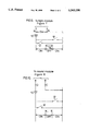
- FIG. 1 is a perspective view of a shoe showing both visible and audible signalling means
- FIG. 2 is a schematic top view of FIG. 1, showing the disposition of the signalling means
- FIG. 3 is a perspective view of a shoe showing both visible and audible signalling means in an alternate disposition to that of FIG. 1,
- FIG. 4 is a schematic top view of the shoe of FIG. 3, showing the disposition of the signalling means
- FIG. 5 is a schematic perspective view of the signalling and control modules associated with the arrangement of FIG. 1,
- FIG. 6 is a schematic wiring diagram of the control module of FIG. 5,
- FIG. 7 is a schematic wiring diagram of the light module of FIG. 5,
- FIG. 8 is a schematic wiring diagram of the sound module of FIG. 5,
- FIG. 9 is a schematic view of the operation of a movable magnet and reed switch to determine the operation of a light emitting diode (LED),
- LED light emitting diode
- FIG. 10 is a schematic view of the operation of a movable magnet and reed switch to determine the operation of a sound synthesizer
- FIG. 11 schematically demonstrates the action of a linearly movable spring biased magnet, on a reed switch
- FIG. 11A shows an alternative construction to FIG. 11,
- FIG. 12 schematically demonstrates the action of a linearly movable magnetically biased magnet on a reed switch
- FIG. 12A shows an alternative construction of FIG. 12,
- FIG. 13 is a perspective schematic view of a magnet and reed switch
- FIG. 14 in section, and illustrates the use of an air driven magnet with a reed switch
- FIG. 14A shows an alternative construction to FIG. 14.
- FIG. 15 shows, in perspective the use of an air driven magnet with a reed switch
- FIG. 16 shows a rotary driven magnet for use in controlling a reed switch
- FIG. 17 schematically indicates the heel of a shoe with a linearly slidable magnet therein
- FIG. 18 schematically indicates the heel of a shoe with an air driven magnet and a single air bladder
- FIG. 19 schematically indicates the heel and sole of a shoe with an air driven magnet and double air bladders
- FIG. 20 schematically indicates the heel of a shoe with a rotatably mounted magnet therein
- FIG. 21 is a side view of the heel of FIG. 18 with the single bladder therein,
- FIG. 22 is a side view of the sole and heel of a shoe with the double bladder of FIG. 19.
- shoes in accord with the invention will frequently be designed to provide only light, or only sound signals.
- An ⁇ Actuator ⁇ herein is the component designed to control the state of the reed switch.
- Various actuators are shown in FIGS. 9-22 inclusive.
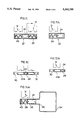
- FIG. 9 shows the basic circuitry for a control module using LED's having battery 10 connected in series with one or more normally open reed switches 12 (which are themselves connected in parallel) and one or more LED's 14 (shown in FIG. 7).
- the LED's are shown connected across terminals at jack elements A,B to illustrate that the LED's may, if desired, be part of a separate plug-in module (see also FIG. 5) for the circuit.
- FIG. 10 demonstrates the analogous circuit using a sound synthesizer 72 (See FIG. 8).
- the sound synthesizer has terminals C,D.
- the sound synthesizer may use any suitable synthesizer integrated circuit ( ⁇ IC ⁇ or ⁇ chip ⁇ 18 but I prefer to use MC 68HC05K0 manufactured by Motorola).
- the battery 10 is connected through one or more the reed switch(es) 12 connected in parallel. The connections may be made through jack elements at C,D if a plug-in module (see FIG. 5) is used.
- the magnet 16 is shown in the neutral or OFF position at which time all reed switches will be open.
- the magnet moves into an ON position in proximity to a reed switch, the corresponding reed switch will close and the closure of either reed switch connects the battery across the C,D terminals activating the sound synthesizer.
- the synthesizer may be programmed to make a variety of sounds at the choice of the programmer, for example ⁇ choo ⁇ for a children's shoe.
- FIG. 11 schematically illustrates an actuator comprising a capsule 22 for embedment in a shoe containing a cylindrical magnet 24, which in this instance may be in either polarity.
- the magnet 24 is biassed toward a central or OFF position by opposed compression springs 26.
- Reed switches 12 for a circuit such as FIGS. 9 or 10 are located adjacent each end of the capsule 22 to be activated when the magnet moves toward such end (an ON position),
- the magnet 16 moves intermittently toward one of the ends and actuates the proximate reed switch 12, to light the LED's 14 (FIG. 7) or activate the sound synthesizer 18, FIG. 8.
- the springs 26 move the magnet to OFF position turning off the visible or audible signal.
- one reed switch 12 only may be used and only one spring 26 located to bias the spring toward an OFF position at the end of capsule 22 remote from the reed switch.
- the spring In the actuator of FIG. 11, and its one spring alternative, the spring must be yielding enough to permit magnet travel to the ON position during walking.
- FIG. 11A shows an alternative construction wherein capsule 22 containing a single spring 26 biases the magnet 24 out of proximity with the single reed switch 12. Under the inertial forces of walking the magnet 24 may move leftward in tube 22 sufficiently to close the single reed switch 12 actuating a sound or light circuit, or both, during the interval ending when the spring 26 moves the magnet 24 out of effective proximity with reed switch 12.
- FIG. 12 shows a capsule 22A with a magnet 24 therein fixed in position at the end of capsule 22A biassed to the central OFF position by the bias magnets 30 and 32. Under the motion of walking or running the inertia of the magnet 24 will cause it to slide toward one end or the other of the capsule against a bias to reach an ON position and activate a reed switch 12 to cause the audible or visual signal as in the circuits of FIG. 9 or 10.
- FIG. 12A shows an alternative construction wherein capsule 28 is associated with a single magnet 30 which biases magnet 24 out of proximity to the single reed switch 12. Under the inertial forces of walking the magnet 24 may move leftward in tube 22 sufficiently to close the single reed switch 12 actuating a sound or light circuit, or both, during the interval ending when the repulsion by the magnet 30 moves the magnet out of effective proximity to reed switch 12.
- FIG. 13 is a schematic indication of an actuator capsule 22A (omitting the springs or bias magnets) a magnet 24 and a reed switch 12.
- FIGS. 14 and 15 a pair of bladders 34 is shown connected to a bore in cylinder 36 wherein a magnet 24 is shaped to act like a piston in a piston cylinder.
- Springs 38 bear on stops 40.
- FIG. 14 the leftward or rightward movement of the magnet 24 is limited by bias springs 38 and the magnet 24.
- the springs drive the magnet 24 to a central location, that is to the OFF position away from either reed switch 12.
- each bladder 34 volume is intermittently compressed and the air (or liquid) contents of the bladder move the magnet rightward or leftward to the ON position to close the reed switch and activate a visible or audible signal in accord with the circuitry of FIGS. 9 or 10.
- magnetic biassing by analogy to FIG. 12 may be used.
- a single bladder and reed switch may be used.
- excursions of the magnet 24 may only be allowed in one direction and a single reed switch used.
- FIG. 14A shows an alternative construction where cylinder 36 is connected to a single bladder 34 and, opposite the bladder, contains a single spring 38 biasing the magnet 24 out of effective proximity to the single reed switch 12. Under pressure from bladder 34 the magnet 24 may move leftward in cylinder 36 sufficiently to close the single reed switch 12 activating a sound or light circuit, or both, during the interval ending when spring 38 moves the magnet out of effective proximity to reed switch 12.
- FIGS. 16 and 20 show an alternative means for controlling the reed switch.
- the magnet 24P is pivotally mounted like a flywheel with polarity as shown.
- Stationary bias magnets 52 and 54 are both designed to be polarized south toward the locus of magnet 24P with the rotating magnet polarity as shown.
- the north pole of rotatable magnet 24P is held over one of the stationary magnets and the rotating magnet is kept in one of two OFF positions remote from either reed switches 12, so that these are open and the circuit of either FIG. 1 or FIG. 2 is inactive.
- the magnet 24P rotates or oscillates through an arc, from time to time closing a reed switch 12 and actuating the circuit of FIG. 9 or 10 to produce the audible or visual signal.
- the magnet 24P may be constrained to oscillate through a small arc between an ON position and an OFF position, the latter determined by a magnet such as 54.
- FIGS. 1-4 show a running shoe 60 with a cavity in the heel containing the control module 64 a light module 70 and sound module 72.
- the light module and the sound module may be used together or as alternates.
- FIG. 5 shows the control module having female connections for jack connections A,B,C and D, corresponding to those shown in FIGS. 6-10 and adapted to receive either the light module or the sound module or both. These may be plugged directly into the control module, as shown to be located in the heel, as indicated by FIGS. 1 and 2 or the light and sound output devices LED's 14 or speaker 15) may be remotely located and connected by appropriate leads 76 as illustrated in FIGS. 3 and 4. Although such leads 76 may be wires moulded into the shoe I would prefer to use CAPTON (TM) film circuitry a thin plastic film with the conductor 76 printed on it produced by Dupont Chemical Co. and sold under the trade mark PYRALUX.
- CAPTON TM film circuitry a thin plastic film with the conductor 76 printed on it
- FIGS. 17-20 the actuator tube is located near the control module 64 with the reed switch inside module 64 and this is suitable for the inertial and spinning magnet application of FIGS. 9-14, and 16.
- the bladder operated actuator for the actuation of the device in FIGS. 14 and 15 must, as shown in FIGS. 14 and 15 be located in the sole or heel of the shoe as shown in FIGS. 18 and 19.
- FIG. 19 shows a double bladder 34 design as shown in FIGS. 14 and 15 and the physical disposition of the bladders 34 is indicated in FIG. 22.
- FIG. 18 shows a single bladder design, discussed previously and FIG. 21 shows its disposition in the heel of a shoe.
- control module 64 of FIG. 6 will be obvious. Responsive to movement of a permanent magnet 16 or 24 (not shown in FIG. 6) into suitable proximity to reed switch 12, the latter will close, connecting battery power across terminals A and B on the one hand and across terminals C and D on the other hand.
- the LED's will light as soon as power is connected across terminals A and B.
- sound synthesizer integrated circuit ⁇ IC ⁇ or ⁇ chip ⁇ 18 is, as stated, preferably that manufactured by Motorola under number MC68HC05K0.
- the positive lead from terminal D is connected to the positive terminal P of IC 18 and the negative lead is connected to negative IC terminal N.
- a modulated output from terminal M is applied to the base of transistor amplifier 73.
- the amplified output is applied to the speaker 15 to produce the sound.
- the synthesizer will give a choice of sounds including a sound similar to the sound ⁇ choo ⁇ for children's shoes.
- the resistance 75 is connected in parallel with the speaker 15 and typically has the value 303 K ⁇ .
- Other sound synthesizers with their own characteristic connections are within the scope of the invention.
- any shoe may have a light module alone, a sound module alone or both. On closure of the reed switch due to movement of the magnet during walking, the connected module is activated and light sound or both are produced until the reed switch is opened.
Abstract
Description
Claims (9)
Priority Applications (7)
| Application Number | Priority Date | Filing Date | Title |
|---|---|---|---|
| CA002078270A CA2078270C (en) | 1992-09-15 | 1992-09-15 | Signalling footwear |
| US07/944,923 US5343190A (en) | 1992-09-15 | 1992-09-15 | Signalling footwear |
| EP93307237A EP0589607A1 (en) | 1992-09-15 | 1993-09-14 | Signalling footwear |
| CN93119270A CN1089458A (en) | 1992-09-15 | 1993-09-15 | A kind of footwear that send signal |
| BR9303791A BR9303791A (en) | 1992-09-15 | 1993-09-15 | Footwear article |
| JP5230387A JPH06189808A (en) | 1992-09-15 | 1993-09-16 | Shoe article |
| US08/160,185 US5422628A (en) | 1992-09-15 | 1993-12-02 | Reed switch actuated circuit |
Applications Claiming Priority (2)
| Application Number | Priority Date | Filing Date | Title |
|---|---|---|---|
| CA002078270A CA2078270C (en) | 1992-09-15 | 1992-09-15 | Signalling footwear |
| US07/944,923 US5343190A (en) | 1992-09-15 | 1992-09-15 | Signalling footwear |
Related Child Applications (1)
| Application Number | Title | Priority Date | Filing Date |
|---|---|---|---|
| US08/160,185 Continuation-In-Part US5422628A (en) | 1992-09-15 | 1993-12-02 | Reed switch actuated circuit |
Publications (1)
| Publication Number | Publication Date |
|---|---|
| US5343190A true US5343190A (en) | 1994-08-30 |
Family
ID=25675522
Family Applications (2)
| Application Number | Title | Priority Date | Filing Date |
|---|---|---|---|
| US07/944,923 Expired - Lifetime US5343190A (en) | 1992-09-15 | 1992-09-15 | Signalling footwear |
| US08/160,185 Expired - Fee Related US5422628A (en) | 1992-09-15 | 1993-12-02 | Reed switch actuated circuit |
Family Applications After (1)
| Application Number | Title | Priority Date | Filing Date |
|---|---|---|---|
| US08/160,185 Expired - Fee Related US5422628A (en) | 1992-09-15 | 1993-12-02 | Reed switch actuated circuit |
Country Status (6)
| Country | Link |
|---|---|
| US (2) | US5343190A (en) |
| EP (1) | EP0589607A1 (en) |
| JP (1) | JPH06189808A (en) |
| CN (1) | CN1089458A (en) |
| BR (1) | BR9303791A (en) |
| CA (1) | CA2078270C (en) |
Cited By (48)
| Publication number | Priority date | Publication date | Assignee | Title |
|---|---|---|---|---|
| US5422628A (en) * | 1992-09-15 | 1995-06-06 | Rodgers; Nicholas A. | Reed switch actuated circuit |
| US5438493A (en) * | 1994-06-08 | 1995-08-01 | Tseng; Shen-Ko | Rolling ball-controlled light emitting device for shoes |
| US5465197A (en) * | 1994-06-07 | 1995-11-07 | Chien; Tseng-Lu | Portable light |
| US5483759A (en) * | 1994-02-01 | 1996-01-16 | Genesco Inc. | Footwear or other products |
| US5570655A (en) * | 1993-12-24 | 1996-11-05 | Targa; Anthony | Device for controlling animal access to a location |
| US5599088A (en) * | 1995-08-21 | 1997-02-04 | Chien; Tseng L. | Flashing footwear light module |
| US5644858A (en) * | 1993-12-02 | 1997-07-08 | L.A. Gear, Inc. | Inertially responsive footwear lights |
| US5748087A (en) * | 1996-08-01 | 1998-05-05 | Ingargiola; Thomas R. | Remote personal security alarm system |
| US5876108A (en) * | 1995-08-03 | 1999-03-02 | Chien; Tseng Lu | Illuminated rotating object |
| US5903103A (en) * | 1997-03-13 | 1999-05-11 | Garner; Melvin C. | Sequential flashing footwear |
| US5921653A (en) * | 1995-05-02 | 1999-07-13 | Chien; Tseng-Lu | Super-thin lighting arrangement for a moving object |
| US5955957A (en) * | 1997-06-17 | 1999-09-21 | Calabrese; Stephen | Footwear with electroluminescent wire |
| US5969479A (en) * | 1997-11-04 | 1999-10-19 | Cheerine Development (Hong Kong) Ltd. | Light flashing system |
| USRE37220E1 (en) | 1993-03-22 | 2001-06-12 | Carmen Rapisarda | Module to provide intermittent light with movement |
| US6280344B1 (en) | 1998-10-22 | 2001-08-28 | Ebonite International, Inc. | Luminous bowling ball |
| US6463691B1 (en) * | 1998-08-19 | 2002-10-15 | Michael R. Atkins | Magnetically actuated indicator device for a fishing rod, fishing rig incorporating the device, and method of using same |
| US20040051474A1 (en) * | 2002-09-04 | 2004-03-18 | Wong Wai Kai | Articles with flashing lights |
| US6788201B2 (en) | 2002-11-05 | 2004-09-07 | Skechers U.S.A., Inc. Ii | Motion sensitive switch and circuitry |
| US20040255490A1 (en) * | 2001-08-01 | 2004-12-23 | Wan Kin Yip | Article of apparel |
| US20050011737A1 (en) * | 2003-07-14 | 2005-01-20 | Wong Wai Kai | Inertia switch and flashing light system |
| US20050024852A1 (en) * | 2003-07-31 | 2005-02-03 | Wong Wai Kai | Letter flashing system for footwear and personal articles |
| US20050134191A1 (en) * | 2003-12-23 | 2005-06-23 | Wong Wai K. | Flashing light system with multiple voltages |
| US20050150138A1 (en) * | 2004-01-08 | 2005-07-14 | Bbc International, Ltd. | Clothing with externally activated switch |
| EP1600069A1 (en) * | 2004-05-24 | 2005-11-30 | BBC International, Ltd. | Footwear with externally activated switch |
| FR2871032A1 (en) * | 2004-06-02 | 2005-12-09 | Xiaoli Bouiller | Shoe, has electromechanical system supplied by electrical storage battery and flashing lamps positioned in heel of outsole or on upper part of shoe, and musical system located in heel of outsole on upper part of shoe |
| US7004598B2 (en) | 2003-02-18 | 2006-02-28 | Cheerine Development (Hong Kong) Ltd. | Flashing light system with power selection |
| US20060080868A1 (en) * | 2004-10-19 | 2006-04-20 | Fang-Lin Chi | Call display and vibration-sensed light emitting shoe heel |
| US7057354B2 (en) | 2003-09-15 | 2006-06-06 | Cheerine Development (Hong Kong) Limited | Frequency controlled lighting system |
| US20060132314A1 (en) * | 2004-12-06 | 2006-06-22 | Sokrethya Sok | Safety alarm for use with footwear |
| US7067986B2 (en) | 2003-09-15 | 2006-06-27 | Cheerine Development (Hong Kong) Limited | Frequency controlled lighting system |
| US7178929B2 (en) | 2004-11-12 | 2007-02-20 | Bbc International, Ltd. | Light and sound producing system |
| US7207688B2 (en) | 2005-08-18 | 2007-04-24 | Wong Wai Yuen | Interactive shoe light device |
| US20090107009A1 (en) * | 2006-05-03 | 2009-04-30 | Ashton Walter Bishop | Footwear |
| US20090251077A1 (en) * | 2008-04-03 | 2009-10-08 | Donald Wilborn | Article of clothing with washable light module |
| US20100115799A1 (en) * | 2008-11-13 | 2010-05-13 | Brady Welter | Shoe Apparatus |
| US20110148621A1 (en) * | 2008-06-04 | 2011-06-23 | Helge Neukirch | Device with magnet arrangement |
| US20110266904A1 (en) * | 2008-08-04 | 2011-11-03 | Cesare Stefanini | Permanent magnet actuator for adaptive actuation |
| US20130033042A1 (en) * | 2011-08-03 | 2013-02-07 | Energy Harvesters Llc | Method and apparatus for generating electrical energy |
| US8469535B2 (en) | 2010-06-17 | 2013-06-25 | Bbc International Llc | Interactive lighted footwear |
| US20170265584A1 (en) * | 2016-03-15 | 2017-09-21 | Nike, Inc. | Foot presence sensing using magnets in footwear |
| US20180007996A1 (en) * | 2016-07-06 | 2018-01-11 | MSG Sports and Entertainment, LLC | Wireless microphone system for an article of footwear |
| US10667576B2 (en) * | 2014-08-13 | 2020-06-02 | Adidas Ag | Co-molded 3D elements |
| US11026481B2 (en) | 2016-03-15 | 2021-06-08 | Nike, Inc. | Foot presence signal processing using velocity |
| US11064768B2 (en) | 2016-03-15 | 2021-07-20 | Nike, Inc. | Foot presence signal processing using velocity |
| US20220142292A1 (en) * | 2019-03-27 | 2022-05-12 | Nec Corporation | Insole-type electronic device and method for manufacturing insole-type electronic device |
| US11357290B2 (en) | 2016-03-15 | 2022-06-14 | Nike, Inc. | Active footwear sensor calibration |
| US11407191B2 (en) | 2016-05-24 | 2022-08-09 | Adidas Ag | Method for the manufacture of a shoe sole, shoe sole, and shoe with pre-manufactured TPU article |
| US11938697B2 (en) | 2016-05-24 | 2024-03-26 | Adidas Ag | Method and apparatus for automatically manufacturing shoe soles |
Families Citing this family (48)
| Publication number | Priority date | Publication date | Assignee | Title |
|---|---|---|---|---|
| WO1995026652A1 (en) * | 1994-04-01 | 1995-10-12 | Bbc International, Ltd. | Footwear having provisions for accepting modules |
| US5771178A (en) * | 1995-06-12 | 1998-06-23 | Scully Signal Company | Fail-safe fluid transfer controller |
| US5777552A (en) * | 1995-08-02 | 1998-07-07 | Sentrol, Inc. | Curtain door alarm |
| US5765300A (en) * | 1995-12-28 | 1998-06-16 | Kianka; Michael | Shoe activated sound synthesizer device |
| US6012822A (en) | 1996-11-26 | 2000-01-11 | Robinson; William J. | Motion activated apparel flasher |
| US6073181A (en) * | 1997-06-03 | 2000-06-06 | International Business Machines Corporation | Multi-buffer error detection for an open data-link interface LAN adapter |
| US5909088A (en) * | 1997-06-27 | 1999-06-01 | East Asia Services Ltd. | Motion activated illuminating footwear and light module therefor with sequential oscillating lights |
| GB2327153B (en) | 1997-07-07 | 2002-03-20 | Nokia Mobile Phones Ltd | A radio device |
| US6493652B1 (en) | 1997-10-02 | 2002-12-10 | Personal Electronic Devices, Inc. | Monitoring activity of a user in locomotion on foot |
| US6876947B1 (en) | 1997-10-02 | 2005-04-05 | Fitsense Technology, Inc. | Monitoring activity of a user in locomotion on foot |
| US6611789B1 (en) | 1997-10-02 | 2003-08-26 | Personal Electric Devices, Inc. | Monitoring activity of a user in locomotion on foot |
| US6882955B1 (en) | 1997-10-02 | 2005-04-19 | Fitsense Technology, Inc. | Monitoring activity of a user in locomotion on foot |
| US6298314B1 (en) | 1997-10-02 | 2001-10-02 | Personal Electronic Devices, Inc. | Detecting the starting and stopping of movement of a person on foot |
| US6018705A (en) * | 1997-10-02 | 2000-01-25 | Personal Electronic Devices, Inc. | Measuring foot contact time and foot loft time of a person in locomotion |
| US5894201A (en) * | 1997-11-04 | 1999-04-13 | Cheerine Development (Hong Kong) Ltd | Light flashing system |
| US6000149A (en) * | 1998-10-30 | 1999-12-14 | Pomerantz; David | Audio shoe |
| US6002091A (en) * | 1998-11-18 | 1999-12-14 | Breed Automotive Technology, Inc. | Bi-directional shock sensor employing reed switch |
| GB2352551A (en) * | 1999-07-23 | 2001-01-31 | Bbc Internat | Sound generating electronic shoes with alarm |
| US6760457B1 (en) | 2000-09-11 | 2004-07-06 | Micro Ear Technology, Inc. | Automatic telephone switch for hearing aid |
| US7248713B2 (en) | 2000-09-11 | 2007-07-24 | Micro Bar Technology, Inc. | Integrated automatic telephone switch |
| AU2002255568B8 (en) | 2001-02-20 | 2014-01-09 | Adidas Ag | Modular personal network systems and methods |
| US6599166B2 (en) | 2001-04-27 | 2003-07-29 | Steven Ellman | Method and device for causing a toy to simulate a condition, such as yawn or sleep |
| KR100370374B1 (en) * | 2001-06-08 | 2003-02-05 | 주도씨엔피 주식회사 | Running shoes with radiator and producing electric power |
| US7447325B2 (en) * | 2002-09-12 | 2008-11-04 | Micro Ear Technology, Inc. | System and method for selectively coupling hearing aids to electromagnetic signals |
| US7369671B2 (en) * | 2002-09-16 | 2008-05-06 | Starkey, Laboratories, Inc. | Switching structures for hearing aid |
| US8284970B2 (en) | 2002-09-16 | 2012-10-09 | Starkey Laboratories Inc. | Switching structures for hearing aid |
| US7059739B2 (en) * | 2002-10-17 | 2006-06-13 | Cheerine Development (Hong Kong) Ltd. | Skates with flashing lights |
| US20040172856A1 (en) * | 2003-03-06 | 2004-09-09 | Tek Nek Toys International, Inc. | Role-playing shoes with sound and light |
| US7262557B1 (en) * | 2003-07-01 | 2007-08-28 | Zhong Wang | Apparatus for illuminating footwear |
| KR200330633Y1 (en) * | 2003-07-07 | 2003-10-17 | 이태성 | Remote responded shoes |
| US20050183294A1 (en) * | 2004-02-19 | 2005-08-25 | Bbc International, Ltd. | Shoe with light and sound activated manually and automatically |
| US7189137B2 (en) | 2004-05-17 | 2007-03-13 | Steven Ellman | Tearing mechanism for a toy, such as a doll, having fixed or movable eyes |
| CA2565072A1 (en) * | 2004-06-02 | 2005-12-22 | Steven Ellman | Expression mechanism for a toy, such as a doll, having fixed or movable eyes |
| US8041066B2 (en) | 2007-01-03 | 2011-10-18 | Starkey Laboratories, Inc. | Wireless system for hearing communication devices providing wireless stereo reception modes |
| US9774961B2 (en) | 2005-06-05 | 2017-09-26 | Starkey Laboratories, Inc. | Hearing assistance device ear-to-ear communication using an intermediate device |
| CN105192985B (en) * | 2005-06-27 | 2017-09-22 | 耐克创新有限合伙公司 | Carry out the system with footwear operation and other purposes for activation and/or certification electronic installation |
| US8028443B2 (en) | 2005-06-27 | 2011-10-04 | Nike, Inc. | Systems for activating and/or authenticating electronic devices for operation with footwear |
| NL1030464C2 (en) | 2005-11-18 | 2007-05-21 | Nedap Agri B V | Motion detector for animals. |
| US8188868B2 (en) | 2006-04-20 | 2012-05-29 | Nike, Inc. | Systems for activating and/or authenticating electronic devices for operation with apparel |
| US8208642B2 (en) | 2006-07-10 | 2012-06-26 | Starkey Laboratories, Inc. | Method and apparatus for a binaural hearing assistance system using monaural audio signals |
| CN101295458A (en) * | 2007-04-27 | 2008-10-29 | 富士迈半导体精密工业(上海)有限公司 | Display equipment and method for displaying information |
| CN101488417A (en) * | 2008-01-18 | 2009-07-22 | 鹏智科技(深圳)有限公司 | Shock switch |
| EP2265341A1 (en) | 2008-04-02 | 2010-12-29 | Nike International Ltd. | Wearable device assembly having athletic functionality |
| US9420385B2 (en) | 2009-12-21 | 2016-08-16 | Starkey Laboratories, Inc. | Low power intermittent messaging for hearing assistance devices |
| US10003379B2 (en) | 2014-05-06 | 2018-06-19 | Starkey Laboratories, Inc. | Wireless communication with probing bandwidth |
| IT201700040113A1 (en) * | 2017-04-11 | 2018-10-11 | Raiot Srl | Footwear for cycling |
| WO2019040797A1 (en) | 2017-08-23 | 2019-02-28 | Pace, Llc | Gait feedback system |
| CN109730396B (en) * | 2019-01-30 | 2022-09-30 | 厦门敏踏鞋业有限公司 | Suction trachea air sac shoes |
Citations (11)
| Publication number | Priority date | Publication date | Assignee | Title |
|---|---|---|---|---|
| US3859651A (en) * | 1974-01-14 | 1975-01-07 | Jr Thomas W Thomas | Boom angle indicator |
| US3960376A (en) * | 1972-07-24 | 1976-06-01 | Berlin Evan H | Balancing skill game |
| US4264899A (en) * | 1978-09-01 | 1981-04-28 | Menzies John I | Portable alarm for entry detection |
| US4298910A (en) * | 1980-02-19 | 1981-11-03 | Rjm Industries, Inc. | Roller skate wheel with self-contained generator |
| US4339747A (en) * | 1979-11-13 | 1982-07-13 | Maybee Richard C | Burglar alarm |
| US4350853A (en) * | 1980-11-18 | 1982-09-21 | The United States Of America As Represented By The Department Of Energy | Alarm toe switch |
| US4588387A (en) * | 1984-02-27 | 1986-05-13 | Neptune Corporation | Illuminated infant toy |
| US4737774A (en) * | 1986-08-15 | 1988-04-12 | Compucap, Inc. | Magnet based activity sensor |
| US4771394A (en) * | 1986-02-03 | 1988-09-13 | Puma Aktiengesellschaft Rudolf Dassler Sport | Computer shoe system and shoe for use therewith |
| US4848009A (en) * | 1988-03-07 | 1989-07-18 | Rodgers Nicholas A | Flashing footwear |
| EP0335467A1 (en) * | 1988-03-30 | 1989-10-04 | Intermedium B.V. | Footwear |
Family Cites Families (6)
| Publication number | Priority date | Publication date | Assignee | Title |
|---|---|---|---|---|
| US2572760A (en) * | 1948-01-15 | 1951-10-23 | Rikelman Nathan | Illuminated shoe device |
| US3618059A (en) * | 1968-06-19 | 1971-11-02 | Milton F Allen | Electronic detection and tracing means |
| GB2089015A (en) * | 1980-12-08 | 1982-06-16 | Tang Chuen | Improvements in waterproof light emitting devices |
| CA1193436A (en) * | 1984-10-11 | 1985-09-17 | Isabella Ziemlinski | Footwear with orientation signal device |
| WO1991018374A1 (en) * | 1990-05-12 | 1991-11-28 | Edgar Stephen Roy Dakin | Visibility aid |
| US5343190A (en) * | 1992-09-15 | 1994-08-30 | Rodgers Nicholas A | Signalling footwear |
-
1992
- 1992-09-15 US US07/944,923 patent/US5343190A/en not_active Expired - Lifetime
- 1992-09-15 CA CA002078270A patent/CA2078270C/en not_active Expired - Fee Related
-
1993
- 1993-09-14 EP EP93307237A patent/EP0589607A1/en not_active Withdrawn
- 1993-09-15 BR BR9303791A patent/BR9303791A/en not_active Application Discontinuation
- 1993-09-15 CN CN93119270A patent/CN1089458A/en active Pending
- 1993-09-16 JP JP5230387A patent/JPH06189808A/en active Pending
- 1993-12-02 US US08/160,185 patent/US5422628A/en not_active Expired - Fee Related
Patent Citations (11)
| Publication number | Priority date | Publication date | Assignee | Title |
|---|---|---|---|---|
| US3960376A (en) * | 1972-07-24 | 1976-06-01 | Berlin Evan H | Balancing skill game |
| US3859651A (en) * | 1974-01-14 | 1975-01-07 | Jr Thomas W Thomas | Boom angle indicator |
| US4264899A (en) * | 1978-09-01 | 1981-04-28 | Menzies John I | Portable alarm for entry detection |
| US4339747A (en) * | 1979-11-13 | 1982-07-13 | Maybee Richard C | Burglar alarm |
| US4298910A (en) * | 1980-02-19 | 1981-11-03 | Rjm Industries, Inc. | Roller skate wheel with self-contained generator |
| US4350853A (en) * | 1980-11-18 | 1982-09-21 | The United States Of America As Represented By The Department Of Energy | Alarm toe switch |
| US4588387A (en) * | 1984-02-27 | 1986-05-13 | Neptune Corporation | Illuminated infant toy |
| US4771394A (en) * | 1986-02-03 | 1988-09-13 | Puma Aktiengesellschaft Rudolf Dassler Sport | Computer shoe system and shoe for use therewith |
| US4737774A (en) * | 1986-08-15 | 1988-04-12 | Compucap, Inc. | Magnet based activity sensor |
| US4848009A (en) * | 1988-03-07 | 1989-07-18 | Rodgers Nicholas A | Flashing footwear |
| EP0335467A1 (en) * | 1988-03-30 | 1989-10-04 | Intermedium B.V. | Footwear |
Cited By (67)
| Publication number | Priority date | Publication date | Assignee | Title |
|---|---|---|---|---|
| US5422628A (en) * | 1992-09-15 | 1995-06-06 | Rodgers; Nicholas A. | Reed switch actuated circuit |
| USRE37220E1 (en) | 1993-03-22 | 2001-06-12 | Carmen Rapisarda | Module to provide intermittent light with movement |
| US5644858A (en) * | 1993-12-02 | 1997-07-08 | L.A. Gear, Inc. | Inertially responsive footwear lights |
| US5570655A (en) * | 1993-12-24 | 1996-11-05 | Targa; Anthony | Device for controlling animal access to a location |
| US5483759A (en) * | 1994-02-01 | 1996-01-16 | Genesco Inc. | Footwear or other products |
| US5465197A (en) * | 1994-06-07 | 1995-11-07 | Chien; Tseng-Lu | Portable light |
| US5438493A (en) * | 1994-06-08 | 1995-08-01 | Tseng; Shen-Ko | Rolling ball-controlled light emitting device for shoes |
| US5921653A (en) * | 1995-05-02 | 1999-07-13 | Chien; Tseng-Lu | Super-thin lighting arrangement for a moving object |
| US5876108A (en) * | 1995-08-03 | 1999-03-02 | Chien; Tseng Lu | Illuminated rotating object |
| US5599088A (en) * | 1995-08-21 | 1997-02-04 | Chien; Tseng L. | Flashing footwear light module |
| US5748087A (en) * | 1996-08-01 | 1998-05-05 | Ingargiola; Thomas R. | Remote personal security alarm system |
| US5903103A (en) * | 1997-03-13 | 1999-05-11 | Garner; Melvin C. | Sequential flashing footwear |
| US5955957A (en) * | 1997-06-17 | 1999-09-21 | Calabrese; Stephen | Footwear with electroluminescent wire |
| US5969479A (en) * | 1997-11-04 | 1999-10-19 | Cheerine Development (Hong Kong) Ltd. | Light flashing system |
| US6463691B1 (en) * | 1998-08-19 | 2002-10-15 | Michael R. Atkins | Magnetically actuated indicator device for a fishing rod, fishing rig incorporating the device, and method of using same |
| US6280344B1 (en) | 1998-10-22 | 2001-08-28 | Ebonite International, Inc. | Luminous bowling ball |
| US20040255490A1 (en) * | 2001-08-01 | 2004-12-23 | Wan Kin Yip | Article of apparel |
| US20040051474A1 (en) * | 2002-09-04 | 2004-03-18 | Wong Wai Kai | Articles with flashing lights |
| US6906472B2 (en) | 2002-09-04 | 2005-06-14 | Cheerine Development (Hong Kong) Ltd. | Articles with flashing lights |
| US6788201B2 (en) | 2002-11-05 | 2004-09-07 | Skechers U.S.A., Inc. Ii | Motion sensitive switch and circuitry |
| US7004598B2 (en) | 2003-02-18 | 2006-02-28 | Cheerine Development (Hong Kong) Ltd. | Flashing light system with power selection |
| US20050011737A1 (en) * | 2003-07-14 | 2005-01-20 | Wong Wai Kai | Inertia switch and flashing light system |
| US7170019B2 (en) | 2003-07-14 | 2007-01-30 | Cheerine Development (Hong Kong), Ltd. | Inertia switch and flashing light system |
| US20050024852A1 (en) * | 2003-07-31 | 2005-02-03 | Wong Wai Kai | Letter flashing system for footwear and personal articles |
| US7067986B2 (en) | 2003-09-15 | 2006-06-27 | Cheerine Development (Hong Kong) Limited | Frequency controlled lighting system |
| US7057354B2 (en) | 2003-09-15 | 2006-06-06 | Cheerine Development (Hong Kong) Limited | Frequency controlled lighting system |
| US20050134191A1 (en) * | 2003-12-23 | 2005-06-23 | Wong Wai K. | Flashing light system with multiple voltages |
| US7029140B2 (en) | 2003-12-23 | 2006-04-18 | Cheerine Development (Hong Kong) Ltd. | Flashing light system with multiple voltages |
| US7254910B2 (en) | 2004-01-08 | 2007-08-14 | Bbc International, Ltd. | Footwear with externally activated switch |
| US20050150138A1 (en) * | 2004-01-08 | 2005-07-14 | Bbc International, Ltd. | Clothing with externally activated switch |
| US7096607B2 (en) * | 2004-01-08 | 2006-08-29 | Bbc International, Ltd. | Clothing with externally activated switch |
| EP1600069A1 (en) * | 2004-05-24 | 2005-11-30 | BBC International, Ltd. | Footwear with externally activated switch |
| FR2871032A1 (en) * | 2004-06-02 | 2005-12-09 | Xiaoli Bouiller | Shoe, has electromechanical system supplied by electrical storage battery and flashing lamps positioned in heel of outsole or on upper part of shoe, and musical system located in heel of outsole on upper part of shoe |
| US20060080868A1 (en) * | 2004-10-19 | 2006-04-20 | Fang-Lin Chi | Call display and vibration-sensed light emitting shoe heel |
| US7178929B2 (en) | 2004-11-12 | 2007-02-20 | Bbc International, Ltd. | Light and sound producing system |
| US20060132314A1 (en) * | 2004-12-06 | 2006-06-22 | Sokrethya Sok | Safety alarm for use with footwear |
| US7207688B2 (en) | 2005-08-18 | 2007-04-24 | Wong Wai Yuen | Interactive shoe light device |
| US20090107009A1 (en) * | 2006-05-03 | 2009-04-30 | Ashton Walter Bishop | Footwear |
| US20090251077A1 (en) * | 2008-04-03 | 2009-10-08 | Donald Wilborn | Article of clothing with washable light module |
| US7857477B2 (en) | 2008-04-03 | 2010-12-28 | Bbc Internatinoal Llc | Article of clothing with washable light module |
| US20110148621A1 (en) * | 2008-06-04 | 2011-06-23 | Helge Neukirch | Device with magnet arrangement |
| US20110266904A1 (en) * | 2008-08-04 | 2011-11-03 | Cesare Stefanini | Permanent magnet actuator for adaptive actuation |
| US20100115799A1 (en) * | 2008-11-13 | 2010-05-13 | Brady Welter | Shoe Apparatus |
| US8469535B2 (en) | 2010-06-17 | 2013-06-25 | Bbc International Llc | Interactive lighted footwear |
| US8907505B2 (en) * | 2011-08-03 | 2014-12-09 | Energy Harvesters Llc | Method and apparatus for generating electrical energy |
| US9303628B2 (en) | 2011-08-03 | 2016-04-05 | Grumer Lawrence C | Method and apparatus for generating electrical energy |
| US20130033042A1 (en) * | 2011-08-03 | 2013-02-07 | Energy Harvesters Llc | Method and apparatus for generating electrical energy |
| US10667576B2 (en) * | 2014-08-13 | 2020-06-02 | Adidas Ag | Co-molded 3D elements |
| US11284669B2 (en) * | 2014-08-13 | 2022-03-29 | Adidas Ag | Co-molded 3D elements |
| US20210274888A1 (en) * | 2016-03-15 | 2021-09-09 | Nike, Inc. | Foot presence sensing using magnets in footwear |
| US11766095B2 (en) | 2016-03-15 | 2023-09-26 | Nike, Inc. | Foot presence signal processing using velocity |
| US11026481B2 (en) | 2016-03-15 | 2021-06-08 | Nike, Inc. | Foot presence signal processing using velocity |
| US11044967B2 (en) * | 2016-03-15 | 2021-06-29 | Nike, Inc. | Foot presence sensing using magnets in footwear |
| US11064768B2 (en) | 2016-03-15 | 2021-07-20 | Nike, Inc. | Foot presence signal processing using velocity |
| US11071355B2 (en) | 2016-03-15 | 2021-07-27 | Nike, Inc. | Foot presence signal processing systems and methods |
| US11925239B2 (en) | 2016-03-15 | 2024-03-12 | Nike, Inc. | Foot presence sensing systems for active footwear |
| US11213100B2 (en) | 2016-03-15 | 2022-01-04 | Nike, Inc. | Foot presence sensing systems for active footwear |
| US20170265584A1 (en) * | 2016-03-15 | 2017-09-21 | Nike, Inc. | Foot presence sensing using magnets in footwear |
| US11889900B2 (en) | 2016-03-15 | 2024-02-06 | Nike, Inc. | Capacitive foot presence sensing for footwear |
| US11357290B2 (en) | 2016-03-15 | 2022-06-14 | Nike, Inc. | Active footwear sensor calibration |
| US11857029B2 (en) | 2016-03-15 | 2024-01-02 | Nike, Inc. | Foot presence signal processing systems and methods |
| US10758012B2 (en) | 2016-03-15 | 2020-09-01 | Nike, Inc. | Sensing device for footwear |
| US11407191B2 (en) | 2016-05-24 | 2022-08-09 | Adidas Ag | Method for the manufacture of a shoe sole, shoe sole, and shoe with pre-manufactured TPU article |
| US11938697B2 (en) | 2016-05-24 | 2024-03-26 | Adidas Ag | Method and apparatus for automatically manufacturing shoe soles |
| US11478037B2 (en) * | 2016-07-06 | 2022-10-25 | Msg Entertainment Group, Llc | Wireless microphone system for an article of footwear |
| US20180007996A1 (en) * | 2016-07-06 | 2018-01-11 | MSG Sports and Entertainment, LLC | Wireless microphone system for an article of footwear |
| US20220142292A1 (en) * | 2019-03-27 | 2022-05-12 | Nec Corporation | Insole-type electronic device and method for manufacturing insole-type electronic device |
Also Published As
| Publication number | Publication date |
|---|---|
| CA2078270A1 (en) | 1994-03-16 |
| US5422628A (en) | 1995-06-06 |
| CA2078270C (en) | 1999-01-12 |
| JPH06189808A (en) | 1994-07-12 |
| EP0589607A1 (en) | 1994-03-30 |
| CN1089458A (en) | 1994-07-20 |
| BR9303791A (en) | 1994-03-29 |
Similar Documents
| Publication | Publication Date | Title |
|---|---|---|
| US5343190A (en) | Signalling footwear | |
| US5894201A (en) | Light flashing system | |
| US7178929B2 (en) | Light and sound producing system | |
| RU2397000C2 (en) | Toy construction set with functional units | |
| EP1600069B1 (en) | Footwear with externally activated switch | |
| US7482712B2 (en) | DC power supply with input voltage polarity indication | |
| US5969479A (en) | Light flashing system | |
| US20060249096A1 (en) | Light and sound producing pet toy | |
| US4848009A (en) | Flashing footwear | |
| US9878261B1 (en) | Toy reactive to a signal | |
| EP1552761B1 (en) | Article of footwear with externally activated switch | |
| KR100741512B1 (en) | Switch Having Waterproof Function and Waterproof Lantern Using the Same | |
| US5881029A (en) | Device to trigger buzzing of alarm clock | |
| IT9067282A1 (en) | DEVICE TO ANIMATE TOYS, BOOMS AND SIMILAR ITEMS | |
| CN215570331U (en) | Sports chip body for shoes | |
| US7262557B1 (en) | Apparatus for illuminating footwear | |
| CN2495073Y (en) | Illuminating apparatus on shoes | |
| JP2646045B2 (en) | Remote control device | |
| ATE185217T1 (en) | BISTABLE SWITCH ARRANGEMENT | |
| AU782629B2 (en) | Light flashing system | |
| MX2008000636A (en) | Miniature switch and battery holder | |
| JP2004208913A (en) | Rocking toy |
Legal Events
| Date | Code | Title | Description |
|---|---|---|---|
| FPAY | Fee payment |
Year of fee payment: 4 |
|
| AS | Assignment |
Owner name: CABARETE HOLDING BV, NETHERLANDS Free format text: LICENSE;ASSIGNOR:RODGERS, NICHOLAS A.;REEL/FRAME:011763/0317 Effective date: 19961231 |
|
| REMI | Maintenance fee reminder mailed | ||
| REIN | Reinstatement after maintenance fee payment confirmed | ||
| FP | Lapsed due to failure to pay maintenance fee |
Effective date: 20020830 |
|
| FEPP | Fee payment procedure |
Free format text: PETITION RELATED TO MAINTENANCE FEES GRANTED (ORIGINAL EVENT CODE: PMFG); ENTITY STATUS OF PATENT OWNER: LARGE ENTITY |
|
| FPAY | Fee payment |
Year of fee payment: 8 |
|
| SULP | Surcharge for late payment | ||
| PRDP | Patent reinstated due to the acceptance of a late maintenance fee |
Effective date: 20030923 |
|
| STCF | Information on status: patent grant |
Free format text: PATENTED CASE |
|
| FPAY | Fee payment |
Year of fee payment: 12 |
|
| AS | Assignment |
Owner name: CHAMELEON, INC., NEW JERSEY Free format text: AGENCY AGREEMENT, TERMINATION LETTER;ASSIGNORS:ROGERS, NICHOLAS A.;SHAW, NICHOLAS A.;REEL/FRAME:017746/0409 Effective date: 20040630 |