US5343960A - Caterpillar track attachment - Google Patents
Caterpillar track attachment Download PDFInfo
- Publication number
- US5343960A US5343960A US07/941,970 US94197092A US5343960A US 5343960 A US5343960 A US 5343960A US 94197092 A US94197092 A US 94197092A US 5343960 A US5343960 A US 5343960A
- Authority
- US
- United States
- Prior art keywords
- wheels
- vehicle
- tracks
- plow
- attachment according
- Prior art date
- Legal status (The legal status is an assumption and is not a legal conclusion. Google has not performed a legal analysis and makes no representation as to the accuracy of the status listed.)
- Expired - Lifetime
Links
Images


Classifications
-
- E—FIXED CONSTRUCTIONS
- E02—HYDRAULIC ENGINEERING; FOUNDATIONS; SOIL SHIFTING
- E02F—DREDGING; SOIL-SHIFTING
- E02F9/00—Component parts of dredgers or soil-shifting machines, not restricted to one of the kinds covered by groups E02F3/00 - E02F7/00
- E02F9/02—Travelling-gear, e.g. associated with slewing gears
-
- B—PERFORMING OPERATIONS; TRANSPORTING
- B62—LAND VEHICLES FOR TRAVELLING OTHERWISE THAN ON RAILS
- B62D—MOTOR VEHICLES; TRAILERS
- B62D55/00—Endless track vehicles
- B62D55/04—Endless track vehicles with tracks and alternative ground wheels, e.g. changeable from endless track vehicle into wheeled vehicle and vice versa
-
- E—FIXED CONSTRUCTIONS
- E02—HYDRAULIC ENGINEERING; FOUNDATIONS; SOIL SHIFTING
- E02F—DREDGING; SOIL-SHIFTING
- E02F3/00—Dredgers; Soil-shifting machines
- E02F3/04—Dredgers; Soil-shifting machines mechanically-driven
- E02F3/76—Graders, bulldozers, or the like with scraper plates or ploughshare-like elements; Levelling scarifying devices
- E02F3/80—Component parts
Definitions
- the invention relates to caterpillar track vehicle propulsion and more specifically to a heavy duty caterpillar track attachment to be adapted to a vehicle having a drive shaft and a steering mechanism.
- U.S. Pat. No. 1,665,470 which describes a rear-end assembly for power driven vehicles, more specifically tractors.
- the rear-end assembly comprises a transmission mechanism adapted to receive the motive power from the differential of the vehicle, and to transmit it to a pair of rear drive wheels driving a pair of caterpillar tracks. It is assumed that the vehicle had been originally designed to undergo this transformation by having a special corresponding front assembly that is suitable to cooperate with the rear-end assembly. Therefore, if such a front assembly was not previously designed for that purpose, the rear-end assembly cannot be installed on the vehicle.
- the rear drive mechanism of the vehicle has to be mostly replaced by the rear-end assembly which comprises several moving or rotative parts that might as well be subjected to possible breakdown, reducing thereby the reliability of the assembly.
- U.S. Pat. No. 3,710,886 which describes a mechanism for converting a wheeled vehicle into a tracked vehicle.
- the mechanism comprises a pair of track assemblies adapted to be connected to the brake drums of the vehicle in replacement of the normal four wheels.
- the steering mechanism of the vehicle is further implemented through the brake system of the vehicle for controlling braking of the tracks to steer the vehicle.
- Such mechanism requires a complicated installation which leads to the track conversion.
- the whole weight of the vehicle is carried by adaptors joining the track assemblies to the wheels, therefore requiring very strong adaptors that will not be any way suitable for labor on soft or uneven grounds, especially for working the soil or the snow.
- Another object of the invention is to provide such an attachment with reduced cost in built-up while maintaining strongness for heavy work possibilities.
- Another object of the invention is to provide such an attachment with slides instead of the conventional idler wheels for guiding the portion of the tracks on the ground.
- a caterpillar track attachment to be adapted to a vehicle having a drive shaft and a steering mechanism, comprising:
- a frame for supporting said vehicle said frame having securing means for connecting said vehicle onto said frame, and a pair of spaced apart elongated side members around which the tracks are respectively mounted, each of said members having front and rear sets of wheels located substantially at its front and rear extremities for guiding therearound the corresponding track, and straight slide means located at its lower portion between the corresponding rear and front sets of wheels for guiding the corresponding track;
- drive means for transmitting motive power from said drive shaft to said tracks, said drive means being operatively connectable to said drive shaft and engaging said tracks;
- hydraulic means to be coupled to said steering mechanism for providing at least one hydraulic fluid outlet controlled by commands from said steering mechanism;
- said attachment can be adapted to said vehicle by operatively connecting said drive means to said drive shaft, by connecting said frame to said vehicle by said securing means, and by coupling said steering mechanism to said hydraulic means.
- the attachment comprises a rear beam provided with a pair of brackets extending rearwards therefrom for hitching up a plow to said attachment, and said hydraulic fluid outlet is positioned close to said pair of brackets for connecting a hydraulic accessory of said plow to said outlet.
- the attachment is also in combination with the plow, wherein said plow as a grading blade provided with retractile and inclination systems.
- FIG. 1 is a side elevational view of a vehicle to which is adapted thereto a first embodiment of a caterpillar track attachment according to the present invention
- FIG. 2 is a side elevational view of a vehicle to which is adapted thereto a second embodiment of a caterpillar track attachment according to the present invention
- FIG. 3 is a top plan view of a half portion of the attachment shown in FIG. 2;
- FIG. 4 is an enlarged exploded view of the sprocket wheel shown in FIG. 2;
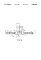
- FIG. 5 is a side elevational view of the vehicle and the attachment shown in FIG. 2, to which is also hitched up a plow, showing how the vehicle is adapted to the attachment;
- FIG. 6 is an enlarged side elevational view of the retractile system of the grading blade shown in FIG. 5;
- FIG. 7 is a front elevational view of the inclination system of a plow's grading blade according to the present invention.
- FIG. 8 is a schematic diagram of the hydraulic system of the vehicle combined with an attachment according to the present invention.
- FIG. 9 is a cross-sectional view taken along line 9--9 of the slide and the track shown in FIG. 1;
- FIG. 10 is a cross-sectional view taken along line 10--10 of the slide and the track shown in FIG. 2;
- FIG. 11 is a cross-sectional view taken along line 11--11 in FIG. 9;
- FIG. 12 is a cross-sectional view taken along line 12--12 in FIG. 9;
- FIG. 13 is a top plan view of the coupling of the plow hitched up to the attachment shown in FIG. 4;
- FIG. 14 shows a side elevational view of axle positioning systems according to the present invention.
- FIG. 15 shows a front elevational view of one of the axle positioning systems shown in FIG. 14.
- a first embodiment of a caterpillar track attachment 2 is adapted to a tractor 4 having a rear drive shaft 6 and, as most of vehicles are provided with, a steering mechanism (not shown in the Figure) used for normally steering the tractor 4.
- the attachment 2 comprises a pair of endless caterpillar tracks 8 respectively on each side of the tractor 4 for propelling it instead of the usual wheels.
- the attachment also comprises a frame 10 for supporting the tractor 4.
- the frame 10 is formed by a pair of spaced apart elongated side members 12, a front transverse beam 14 (shown in dotted lines) and a rear transverse beam 16 (shown in dotted lines) that join each of the side members 12 and fix it all firmly together.
- the tractor 4 is secured to the attachment 2 on these front and rear beams 14 and 16.
- Each of the tracks 8 is mounted around the corresponding one of the side members 12.
- each of the side members 12 is provided with front and rear sets of coaxially aligned idler wheels 22 and 24 for guiding therearound the corresponding track, and a straight slide 26 made of TEFLON (Trade Mark) located at its lower portion between the front and rear sets of idler wheels 22 and 24 for guiding the corresponding track 8 during its course.
- Each of the side members 12 has also at its upper portion three other shorter slides 28, 30 and 32 made of TEFLON and a pair of idler wheels 34 beside the sprocket wheel 36 engaging the corresponding track to guide it during its course between the sprocket wheel 36 and the front set of idler wheels 22.
- the sprocket wheels 36 are fixedly attached at both ends of the drive shaft 6 respectively in direct linkage therewith and in a gearing engagement with the tracks 8.
- the motive power could be transmitted from the drive shaft 6 to the sprocket wheels 36 in various way, such as with coupling gears or belts, allowing to locate the rotation axis of the sprocket wheels 28 at any convenient place for their purpose.
- Each of the tracks 8 has along its entire length tooth-receiving holes set equally apart, that can be engaged by the teeth 38 of the sprocket wheel 36.
- Each of the sprocket wheels 36 has a one-piece hub 40 around which are mounted five arc pieces 39 forming a rim, each of the arc pieces 39 being provided with a group of the teeth 38 that form the entire set of teeth of the sprocket wheel 36 when all the arc pieces 39 are mounted around the hub 40.
- Installation of the sprocket wheels 36 is made easier as each of its pieces 39, 40 is relatively light, instead of a heavy one-piece sprocket wheel.
- the sprocket wheel 36 might as well be formed of a one-piece hub 40 around which is mounted with bolts 41 a one-piece rim 43 provided with the entire set of teeth.
- the rim 43 is made of a polyurethane plastic and an aluminum alloy, thereby providing the same advantages as the prior embodiment of the sprocket wheel 36 while straightening the rim 43 for heavy work.
- each of the side members 12 has a stretch adjuster formed by a telescopic arm 42 having an end connected to the corresponding side member 12, and a pair of coaxially aligned idler wheels 44 attached to an opposite end of the arm 42.
- the stretch is simply adjusted by positioning longitudinally the idler wheels 44 to press up against the corresponding track 8 for producing the desired stretch thereof.
- FIG. 2 there is shown another embodiment of the attachment 2 that differs slightly from the one shown in FIG. 1 in that pairs of coaxially aligned idler wheels 46, 48, 50 are use to guide the tracks 8 on the upper portion of the side members 12, instead of the prior slides 28, 30, 32 (shown in FIG. 1). Two of these pairs of wheels 46 and 48 are positioned on proximity of each sprocket wheel 36 near the locations where the track 8 is engaged and disengaged.
- a second set of idler wheels 44 shown in FIG. 1 for adjusting the track stretch
- each of the side members 12 is provided with a front set of bigger idler wheels 22 directly attached to the front end of the telescopic arm 42 forming the stretch adjuster.
- the front transverse beam 18 is provided with coupling elements 19 for connecting the front part of the tractor 4 to the attachment 2.
- FIG. 3 a top view of a half portion of the frame 10 shown in FIG. 2.
- the other half is symmetrically the same.
- Each pair of idler wheels 22, 24, 34 and 44 is spaced from one another so as to give good support to the tracks 8 while maintaining a certain engagement with them in order to reduce their lateral skid.
- this engagement is maintained by providing the tracks 8 with inwardly projecting pairs of spaced lugs 54 set equally apart from one another on their entire length such that there is always a pair of lugs 54 guiding each of the tracks 8 on these idler wheels 22, 24, 34 and 44.
- FIG. 5 it is shown how the attachment 2 is mounted by firstly fixedly attaching the sprocket wheels 36 to the drive shaft 6 of the tractor 4, secondly placing the tractor 4 onto the attachment 2 and securing the front axle 18 of the tractor 4 to the front beam 14 (shown in FIG. 1 and 2) and bolting the pair of hooks 20 (shown in FIG. 1) to corresponding hooks of the tractor 4, and thirdly setting the tracks (not shown) around each side members 12.
- the attachment 2 is especially useful for converting a simple tractor into a snow grooming vehicle when combined with a special type of rear snow plow 56 having a hydraulic piston 58 that can produce a lever action to force a rotation between the plow 56 and its coupling 60 to the attachment 2 for steering the vehicle.
- the use of slides 26 for guiding the tracks 8 (not shown) instead of conventional idler wheels increases significantly the vehicle's stability, even on bumpy ground. By means of the slides 26, the tracks 8 always lay on top of the bumps without falling into the troughs therebetween.
- the tractor 4 being almost perfectly stable, the plow 56 towed by the tractor 4 operates best for grading the snow.
- the low number of structural parts forming the attachment 2 results in an overall improved reliability since there are less parts that may break down.
- the plow 56 has a grading blade 61 provided with a retractile system 63 for protecting the blade 61 from potentially abusive impacts caused for example by rocks, stumps, etc.
- the grading blade 61 is also provided with an inclination system 65 (shown in FIG. 7) for adjusting an angle of grading with respect to a horizontal plane of the plow 56 in order to reduce centrifugal forces occurring when the vehicle turns and maintain a higher grading quality.
- the retractile system 63 comprises a bracket 67 attached to the main frame of the plow 56, onto which an end of the grading blade 61 is pivotally connected.
- the retractile system 63 also comprises a shock absorber assembly including a shaft 69, a sliding sleeve 71, first and second linking members 99, 75, and a spring 73.
- the shaft 69 has a first end pivotally connected to the bracket 67 and a second end provided with a stop.
- the sliding sleeve 71 is mounted around the shaft 69 and is capable of sliding therealong.
- the first linking member 99 has an end pivotally connected to the bracket 67 and another end pivotally connected to the sleeve 71 at point 96.
- the second linking member 75 has an end pivotally connected to the sleeve 71 at point 96 and another end pivotally connected to the grading blade 61.
- the spring 73 is mounted along the shaft 69 between its stop and the sleeve so that, in operating position when said grading blade 61 rests against the ground, the shaft 69 is held in a bias position by means of the sleeve 71 which is held at its turn in position by means of the linking members 99, 75 which are slightly skewed with one another.
- the grading blade 61 When the grading blade 61 is brought forward for grading the ground and meets a hard obstacle, it pivots with respect to the bracket 67 so that the grading blade 61 can get over the obstacle while the linking members 99, 75 are folded with respect to each other and the sleeve 71 is moved along the shaft 69 toward the stop to compress the spring 73. Once the obstacle passed the grading blade 61 is automatically brought back to its operating position by means of the spring 73.
- the retractile system 63 is extremely hard to retract when the grading blade 61 is in operating position, but once engaged the spring 73 absorbs the impact.
- the grading blade 61 can turn up around the mounting 67 in response to a sufficient retracting force acting thereon, folding then the linking members 99, 75 whose articulations are repelled by the coil spring 73 in opposition to their motion for repositioning thereafter the grading blade 61 in operating position.
- the inclination system 65 is built upon the same brackets 67 as the retractile system 63 shown in FIG. 6.
- the inclination system 65 includes an elongated beam member 77 extending crosswise from side to side of the plow 56.
- the beam member 77 is pivotally connected to one side of the plow 56 so as to pivot around a pivot point 85.
- the beam member 77 is provided with attaching devices along its length that are spaced apart from each other and attached respectively to different portions of the grading blade 61 so that the latter is solid with the beam member 77.
- the inclination system 65 further comprises guides 79 fixed to the main frame of the plow 56 and cooperating with the beam member 77, for restricting the beam member 77 to vertical movements.
- the inclination system 65 further comprises a hydraulic piston 81 having its upper end pivotally connected to a support 83 on the plow 56, and its lower end pivotally connected to the beam member 77 at a predetermined distance from the pivot point 85 in order to obtain the desired lever action.
- the piston 81 has a hydraulic line supplied by the vehicle's steering mechanism (not shown). The angle of grading can be adjusted via commands on the steering mechanism. When the vehicle enters a turn, the inclination of the grader will be proportional to the action of the steering mechanism, i.e. the sharper the turn the more pronounced the oscillation will be.
- FIG. 8 there is shown a schematic diagram of a hydraulic system for controlling the hydraulic piston 58.
- the power steering mechanism of the vehicle comprises a fluid tank 62 that supplies in fluid a hydraulic pump 64 that provides a constant fluid outflow.
- a pressure relief valve 66 regulates the fluid pressure by returning the fluid in the tank 62, while a spool valve 68 is in neutral position and blocks up any flow.
- a command mechanism 70 can be for instance the power steering mechanism of the tractor 4 (shown in FIG. 4) or any suitable lever installed for that purpose.
- a hydraulic line 76 is simply coupled to the power steering mechanism and provides a hydraulic fluid outlet connectable to the hydraulic piston 58 to control.
- other spool valves 72 can be connected to the hydraulic line 74 for possible connections to other hydraulic vehicle accessories such as the front plow 52 (shown in FIG. 4), and the hydraulic piston 81 of the inclination system 65 (shown in FIG. 7), these accessories being suitably controlled with command mechanisms (such as the command mechanism 70) installed for that purpose.
- command mechanisms such as the command mechanism 70
- FIGS. 9 and 10 two embodiments of the sleeves 26 are shown.
- Each of the slides 26 cooperates with the corresponding track 8 for guiding it.
- the second embodiment of the slide 26 shown in FIG. 10 is more suitable for attaching sets of track-bearing idler wheels 39 (shown in FIG. 2) thereto.
- the pair of lugs 54 are sufficiently spaced apart for allowing passage of the slide 26, but close enough to avoid as much as possible lateral skid.
- the tracks 8 are along their entire length also provided with outwardly projecting crosswise treads 76 set substantially equally apart from one another to improve the traction of the tracks 8.
- Each of the treads 76 is secured to the track 8 with bolts and nuts 78.
- the rear transverse beam 16 is provided with a pair of brackets 80 that are used to hitch up the plow 56 to the attachment 2.
- the fluid outlet of the hydraulic line 76 coupled to the power steering mechanism (as shown in FIG. 8) of the tractor 4 is located close to the pair of brackets 80 and is connected to the piston inlet. The vehicle can therefore be steered by pivoting the plow 56 with respect to the attachment 2.
- each of the wheels or set of wheels 22, 24, 39 (as shown in FIG. 1) is provided with a positioning device 90 for adjusting a position of its axle 92 in order to control the slide's wear and improve the smoothness of the track's sliding.
- the positioning device 90 forms a collar into which the axle 92 is tightened by at least three locking elements 94 inwardly projecting from the collar in converging directions at 120° from one another.
- the position of the wheel 22, 24, 39 can be adjusted by varying respectively the projecting portions of the locking elements 94 within the collar.
Landscapes
- Engineering & Computer Science (AREA)
- Mining & Mineral Resources (AREA)
- Civil Engineering (AREA)
- General Engineering & Computer Science (AREA)
- Structural Engineering (AREA)
- Mechanical Engineering (AREA)
- Chemical & Material Sciences (AREA)
- Combustion & Propulsion (AREA)
- Transportation (AREA)
- Agricultural Machines (AREA)
- Non-Deflectable Wheels, Steering Of Trailers, Or Other Steering (AREA)
Abstract
Description
Claims (18)
Priority Applications (2)
| Application Number | Priority Date | Filing Date | Title |
|---|---|---|---|
| CA002077702A CA2077702C (en) | 1992-09-08 | 1992-09-08 | Caterpillar track attachment |
| US07/941,970 US5343960A (en) | 1992-09-08 | 1992-09-08 | Caterpillar track attachment |
Applications Claiming Priority (2)
| Application Number | Priority Date | Filing Date | Title |
|---|---|---|---|
| CA002077702A CA2077702C (en) | 1992-09-08 | 1992-09-08 | Caterpillar track attachment |
| US07/941,970 US5343960A (en) | 1992-09-08 | 1992-09-08 | Caterpillar track attachment |
Publications (1)
| Publication Number | Publication Date |
|---|---|
| US5343960A true US5343960A (en) | 1994-09-06 |
Family
ID=25675501
Family Applications (1)
| Application Number | Title | Priority Date | Filing Date |
|---|---|---|---|
| US07/941,970 Expired - Lifetime US5343960A (en) | 1992-09-08 | 1992-09-08 | Caterpillar track attachment |
Country Status (2)
| Country | Link |
|---|---|
| US (1) | US5343960A (en) |
| CA (1) | CA2077702C (en) |
Cited By (42)
| Publication number | Priority date | Publication date | Assignee | Title |
|---|---|---|---|---|
| US5829848A (en) * | 1995-06-23 | 1998-11-03 | Agtracks, Inc. | Track suspension apparatus for vehicles of various types |
| US5842757A (en) * | 1997-01-31 | 1998-12-01 | Agtracks, Inc. | Track system for vehicles |
| USRE36284E (en) * | 1993-12-13 | 1999-08-31 | Agtracks, Inc. | Track system for vehicles |
| WO2000002765A1 (en) * | 1998-07-10 | 2000-01-20 | Agtracks, Inc. | Guide wheel for flexible track of a track system |
| WO2000002766A1 (en) * | 1998-07-10 | 2000-01-20 | Agtacks, Inc. | Mounting device for track apparatus |
| US6062661A (en) * | 1998-07-10 | 2000-05-16 | Agtracks, Inc. | Track system drive wheel for agricultural implements |
| US6068353A (en) * | 1998-07-10 | 2000-05-30 | Agtracks, Inc. | Track apparatus incorporating non-pneumatic wheels |
| GB2344088A (en) * | 1998-11-27 | 2000-05-31 | Larrington Richard Ltd | Endless-track conversion for a wheeled vehicle |
| US6074025A (en) * | 1998-07-10 | 2000-06-13 | Agtracks, Inc. | Track apparatus incorporating cantilever mounted wheels |
| US6076619A (en) * | 1998-12-10 | 2000-06-20 | Hammer; Adolph | All terrain vehicle for disabled persons |
| US6132133A (en) * | 1996-06-12 | 2000-10-17 | Komatsu Ltd. | Crawler type vibratory compacting machine |
| US6199646B1 (en) * | 1996-08-01 | 2001-03-13 | Kubota Corporation | Working vehicle with semicrawlers |
| US6481123B1 (en) * | 1997-12-31 | 2002-11-19 | Kassbohrer Glandefahrzeug Ag | Track maintenance device |
| US20030079922A1 (en) * | 2001-10-29 | 2003-05-01 | Campbell Jeffery D. | Four wheel drive motorized carrier |
| EP1378426A1 (en) * | 2002-07-05 | 2004-01-07 | Otico | Kit for elastomeric track for motor vehicle, and vehicle equipped with such a kit |
| US20040065487A1 (en) * | 2002-10-08 | 2004-04-08 | Tool Engineering & Manufacturing Company | Rail track vehicle |
| US20040140138A1 (en) * | 2003-01-21 | 2004-07-22 | Glen Brazier | Terrain conforming track assembly |
| US20050035655A1 (en) * | 2003-08-13 | 2005-02-17 | Clark Equipment Company | Track with offset drive lugs and drive wheel therefore |
| US20050056468A1 (en) * | 2003-09-17 | 2005-03-17 | Tucker Sno-Cat Corporation | Tracked vehicle with improved track drive unit |
| US20050076542A1 (en) * | 2003-10-08 | 2005-04-14 | Robert Gregoire | Snow surface grooming apparatus |
| US20050145422A1 (en) * | 2004-01-02 | 2005-07-07 | Loegering Mfg. Inc. | Track assembly |
| US20070017713A1 (en) * | 2005-06-10 | 2007-01-25 | The Charles Machine Works, Inc. | Utility Track Machine With Undercarriage Bogie Rollers |
| WO2007140539A1 (en) | 2006-06-08 | 2007-12-13 | Himachal Helicopter Skiing Pty | Snow traction unit for vehicles |
| WO2008025141A1 (en) * | 2006-08-29 | 2008-03-06 | Rpm Tech Inc. | Steering system for an adaptable vehicle |
| US20090050379A1 (en) * | 2007-08-22 | 2009-02-26 | Clark Equipment Company | Track vehicle having drive and suspension systems |
| US20090116943A1 (en) * | 2006-04-19 | 2009-05-07 | Messeri's P.A. | Compact tracked vehicle for transporting and self-loading material, that can be operated by a standing operator |
| US7552785B2 (en) | 2006-11-02 | 2009-06-30 | Clark Equipment Company | Suspension system for track vehicle |
| US20100060075A1 (en) * | 2006-12-12 | 2010-03-11 | Hansen Ronald S | Conversion System for a Wheeled Vehicle |
| WO2011030994A1 (en) * | 2009-09-09 | 2011-03-17 | Lee Chung-Chul | Tracked vehicle, amphibious track, track shoe for a track, and manually operated steerable tracked vehicle |
| US20110180332A1 (en) * | 2010-01-27 | 2011-07-28 | Les Produits Gilbert Inc. | Steering system for a tracked vehicle |
| US8430188B2 (en) | 2006-12-11 | 2013-04-30 | Vermeer Manufacturing Company | Apparatus for converting a wheeled vehicle to a tracked vehicle |
| US8801115B2 (en) | 2008-12-09 | 2014-08-12 | Vermeer Manufacturing Company | Apparatus for converting a wheeled vehicle to a tracked vehicle |
| US9008913B1 (en) * | 2013-11-22 | 2015-04-14 | Oshkosh Corporation | Steering control system for a towed axle |
| US9033431B1 (en) | 2010-06-30 | 2015-05-19 | Camoplast Solideal Inc | Track assembly for an off-road vehicle |
| US9505454B1 (en) | 2011-06-13 | 2016-11-29 | Camso Inc. | Track assembly for traction of an off-road vehicle |
| US9663164B2 (en) | 2012-07-30 | 2017-05-30 | Cnh Industrial America Llc | Undercarriage system for a tracked work vehicle |
| US9738342B2 (en) | 2014-11-13 | 2017-08-22 | Acorn Products, Llc | Steering assemblies for multi-wheeled vehicles and multi-wheeled vehicles including the steering assemblies |
| CN108487350A (en) * | 2018-04-13 | 2018-09-04 | 新兴移山(天津)重工有限公司 | A kind of machinery bogie frame |
| US10099733B1 (en) * | 2016-02-05 | 2018-10-16 | The Charles Machine Works, Inc. | Endless track and guide member |
| US10875591B2 (en) | 2015-08-04 | 2020-12-29 | Camso Inc. | Track system for traction of an agricultural vehicle travelling on fields and roads |
| US11077897B2 (en) | 2015-10-23 | 2021-08-03 | Camso Manufacturing Italy S.R.L. | Track system for traction of a vehicle |
| US20220266929A1 (en) * | 2021-02-25 | 2022-08-25 | Glen Brazier | Anti-jam track wheel assembly |
Citations (12)
| Publication number | Priority date | Publication date | Assignee | Title |
|---|---|---|---|---|
| US1073759A (en) * | 1912-03-20 | 1913-09-23 | Walter E Huck | Plow. |
| US1665470A (en) * | 1925-11-06 | 1928-04-10 | Emil F Norelius | Rear-end assembly for power-driven vehicles |
| US1810138A (en) * | 1928-07-27 | 1931-06-16 | Marion Machine Foundry & Suppl | Articulated tractor track |
| US2794273A (en) * | 1952-07-02 | 1957-06-04 | Bomford & Evershed Ltd | Attachments for vehicles for traversing heaped up material along the ground |
| US3321027B1 (en) * | 1965-08-26 | 1967-05-23 | ||
| US3710886A (en) * | 1969-06-12 | 1973-01-16 | A Wagner | Mechanism for converting wheeled vehicle into tracked vehicle |
| US3939930A (en) * | 1973-06-21 | 1976-02-24 | Firstenberg Harold S | Vehicle track retention device |
| US3976153A (en) * | 1975-04-25 | 1976-08-24 | Lateur Michel J | Vehicle with removable traction apparatus |
| US4448273A (en) * | 1981-12-18 | 1984-05-15 | Barbieri Louis C | Endless track attachment for a vehicle |
| US4727948A (en) * | 1986-08-06 | 1988-03-01 | Julseth Richard A | Rear crawler track retrofit for garden and lawn tractors |
| US4821824A (en) * | 1988-02-04 | 1989-04-18 | Lloyd Gilbert | Auxiliary traction system |
| US4865141A (en) * | 1987-01-30 | 1989-09-12 | Leo Gey | Device for changing over a vehicle provided with wheels to a track vehicle |
-
1992
- 1992-09-08 US US07/941,970 patent/US5343960A/en not_active Expired - Lifetime
- 1992-09-08 CA CA002077702A patent/CA2077702C/en not_active Expired - Lifetime
Patent Citations (13)
| Publication number | Priority date | Publication date | Assignee | Title |
|---|---|---|---|---|
| US1073759A (en) * | 1912-03-20 | 1913-09-23 | Walter E Huck | Plow. |
| US1665470A (en) * | 1925-11-06 | 1928-04-10 | Emil F Norelius | Rear-end assembly for power-driven vehicles |
| US1810138A (en) * | 1928-07-27 | 1931-06-16 | Marion Machine Foundry & Suppl | Articulated tractor track |
| US2794273A (en) * | 1952-07-02 | 1957-06-04 | Bomford & Evershed Ltd | Attachments for vehicles for traversing heaped up material along the ground |
| US3321027B1 (en) * | 1965-08-26 | 1967-05-23 | ||
| US3321027A (en) * | 1965-08-26 | 1967-05-23 | Int Harvester Co | Self-restoring plow trip |
| US3710886A (en) * | 1969-06-12 | 1973-01-16 | A Wagner | Mechanism for converting wheeled vehicle into tracked vehicle |
| US3939930A (en) * | 1973-06-21 | 1976-02-24 | Firstenberg Harold S | Vehicle track retention device |
| US3976153A (en) * | 1975-04-25 | 1976-08-24 | Lateur Michel J | Vehicle with removable traction apparatus |
| US4448273A (en) * | 1981-12-18 | 1984-05-15 | Barbieri Louis C | Endless track attachment for a vehicle |
| US4727948A (en) * | 1986-08-06 | 1988-03-01 | Julseth Richard A | Rear crawler track retrofit for garden and lawn tractors |
| US4865141A (en) * | 1987-01-30 | 1989-09-12 | Leo Gey | Device for changing over a vehicle provided with wheels to a track vehicle |
| US4821824A (en) * | 1988-02-04 | 1989-04-18 | Lloyd Gilbert | Auxiliary traction system |
Cited By (73)
| Publication number | Priority date | Publication date | Assignee | Title |
|---|---|---|---|---|
| USRE36284E (en) * | 1993-12-13 | 1999-08-31 | Agtracks, Inc. | Track system for vehicles |
| US5829848A (en) * | 1995-06-23 | 1998-11-03 | Agtracks, Inc. | Track suspension apparatus for vehicles of various types |
| US6132133A (en) * | 1996-06-12 | 2000-10-17 | Komatsu Ltd. | Crawler type vibratory compacting machine |
| US6199646B1 (en) * | 1996-08-01 | 2001-03-13 | Kubota Corporation | Working vehicle with semicrawlers |
| US5842757A (en) * | 1997-01-31 | 1998-12-01 | Agtracks, Inc. | Track system for vehicles |
| US6481123B1 (en) * | 1997-12-31 | 2002-11-19 | Kassbohrer Glandefahrzeug Ag | Track maintenance device |
| WO2000002766A1 (en) * | 1998-07-10 | 2000-01-20 | Agtacks, Inc. | Mounting device for track apparatus |
| US6068353A (en) * | 1998-07-10 | 2000-05-30 | Agtracks, Inc. | Track apparatus incorporating non-pneumatic wheels |
| US6074024A (en) * | 1998-07-10 | 2000-06-13 | Agtracks, Inc. | Guide wheel for flexible track of a track system |
| US6074025A (en) * | 1998-07-10 | 2000-06-13 | Agtracks, Inc. | Track apparatus incorporating cantilever mounted wheels |
| US6062661A (en) * | 1998-07-10 | 2000-05-16 | Agtracks, Inc. | Track system drive wheel for agricultural implements |
| US6062662A (en) * | 1998-07-10 | 2000-05-16 | Agtracks, Inc. | Mounting device for track apparatus |
| WO2000002765A1 (en) * | 1998-07-10 | 2000-01-20 | Agtracks, Inc. | Guide wheel for flexible track of a track system |
| GB2344088A (en) * | 1998-11-27 | 2000-05-31 | Larrington Richard Ltd | Endless-track conversion for a wheeled vehicle |
| US6076619A (en) * | 1998-12-10 | 2000-06-20 | Hammer; Adolph | All terrain vehicle for disabled persons |
| US6776248B2 (en) * | 2001-10-29 | 2004-08-17 | Jeffery D. Campbell | Four wheel drive motorized carrier |
| US20030079922A1 (en) * | 2001-10-29 | 2003-05-01 | Campbell Jeffery D. | Four wheel drive motorized carrier |
| EP1378426A1 (en) * | 2002-07-05 | 2004-01-07 | Otico | Kit for elastomeric track for motor vehicle, and vehicle equipped with such a kit |
| US20040017107A1 (en) * | 2002-07-05 | 2004-01-29 | Otico | Vehicle drive device with flexible crawler and vehicle thus obtained |
| FR2841868A1 (en) * | 2002-07-05 | 2004-01-09 | Otico | FLEXIBLE TRACK DRIVE DEVICE FOR MOTOR VEHICLE AND VEHICLE THUS OBTAINED |
| US6981563B2 (en) | 2002-07-05 | 2006-01-03 | Otico | Vehicle drive device with flexible crawler and vehicle thus obtained |
| US20040065487A1 (en) * | 2002-10-08 | 2004-04-08 | Tool Engineering & Manufacturing Company | Rail track vehicle |
| US6854540B2 (en) | 2002-10-08 | 2005-02-15 | Mckinnon Paul G. | Rail track vehicle |
| US20040140138A1 (en) * | 2003-01-21 | 2004-07-22 | Glen Brazier | Terrain conforming track assembly |
| US6904986B2 (en) * | 2003-01-21 | 2005-06-14 | Glen Brazier | Terrain conforming track assembly |
| US20050035655A1 (en) * | 2003-08-13 | 2005-02-17 | Clark Equipment Company | Track with offset drive lugs and drive wheel therefore |
| US20050072607A1 (en) * | 2003-09-17 | 2005-04-07 | Tucker Sno-Cat Corporation | Tracked vehicle with improved track drive unit |
| US20050072606A1 (en) * | 2003-09-17 | 2005-04-07 | Tucker Sno-Cat Corporation | Tracked vehicle with improved track drive unit |
| US20050056469A1 (en) * | 2003-09-17 | 2005-03-17 | Tucker Sno-Cat Corporation | Tracked vehicle with improved track drive unit |
| US7201242B2 (en) | 2003-09-17 | 2007-04-10 | Tucker Sno-Cat Corporation | Tracked vehicle with improved track drive unit |
| US6968914B2 (en) | 2003-09-17 | 2005-11-29 | Tucker Sno-Cat Corporation | Tracked vehicle with improved track drive unit |
| US20050056468A1 (en) * | 2003-09-17 | 2005-03-17 | Tucker Sno-Cat Corporation | Tracked vehicle with improved track drive unit |
| US6983812B2 (en) | 2003-09-17 | 2006-01-10 | Tucker Sno-Cat Corporation | Tracked vehicle with improved track drive unit |
| US20050076542A1 (en) * | 2003-10-08 | 2005-04-14 | Robert Gregoire | Snow surface grooming apparatus |
| US7255184B2 (en) | 2004-01-02 | 2007-08-14 | Loegering Mfg, Inc. | Track assembly |
| US20050145422A1 (en) * | 2004-01-02 | 2005-07-07 | Loegering Mfg. Inc. | Track assembly |
| US20070017713A1 (en) * | 2005-06-10 | 2007-01-25 | The Charles Machine Works, Inc. | Utility Track Machine With Undercarriage Bogie Rollers |
| US20090116943A1 (en) * | 2006-04-19 | 2009-05-07 | Messeri's P.A. | Compact tracked vehicle for transporting and self-loading material, that can be operated by a standing operator |
| WO2007140539A1 (en) | 2006-06-08 | 2007-12-13 | Himachal Helicopter Skiing Pty | Snow traction unit for vehicles |
| WO2008025141A1 (en) * | 2006-08-29 | 2008-03-06 | Rpm Tech Inc. | Steering system for an adaptable vehicle |
| US7552785B2 (en) | 2006-11-02 | 2009-06-30 | Clark Equipment Company | Suspension system for track vehicle |
| US9180910B2 (en) | 2006-12-11 | 2015-11-10 | Vermeer Manufacturing Company | Apparatus for converting a wheeled vehicle to a tracked vehicle |
| US9079614B2 (en) | 2006-12-11 | 2015-07-14 | Vermeer Manufacturing Company | Apparatus for converting a wheeled vehicle to a tracked vehicle |
| US8827013B2 (en) | 2006-12-11 | 2014-09-09 | Vermeer Manufacturing Company | Apparatus for converting a wheeled vehicle to a tracked vehicle |
| US9352776B2 (en) | 2006-12-11 | 2016-05-31 | Vermeer Manufacturing Company | Apparatus for converting a wheeled vehicle to a tracked vehicle |
| US8430188B2 (en) | 2006-12-11 | 2013-04-30 | Vermeer Manufacturing Company | Apparatus for converting a wheeled vehicle to a tracked vehicle |
| US8794358B2 (en) * | 2006-12-12 | 2014-08-05 | Loegering Mfg., Inc. | Conversion system for a wheeled vehicle |
| US20100060075A1 (en) * | 2006-12-12 | 2010-03-11 | Hansen Ronald S | Conversion System for a Wheeled Vehicle |
| US9643667B2 (en) | 2006-12-12 | 2017-05-09 | A.S.V., Llc | Conversion system for a wheeled vehicle |
| US7798260B2 (en) * | 2007-08-22 | 2010-09-21 | Clark Equipment Company | Track vehicle having drive and suspension systems |
| CN101784433B (en) * | 2007-08-22 | 2013-01-30 | 克拉克设备公司 | Track vehicle having drive and suspension systems |
| US20090050379A1 (en) * | 2007-08-22 | 2009-02-26 | Clark Equipment Company | Track vehicle having drive and suspension systems |
| US8801115B2 (en) | 2008-12-09 | 2014-08-12 | Vermeer Manufacturing Company | Apparatus for converting a wheeled vehicle to a tracked vehicle |
| WO2011030994A1 (en) * | 2009-09-09 | 2011-03-17 | Lee Chung-Chul | Tracked vehicle, amphibious track, track shoe for a track, and manually operated steerable tracked vehicle |
| US8157033B2 (en) | 2010-01-27 | 2012-04-17 | Les Produits Gilbert Inc. | Steering system for a tracked vehicle |
| US20110180332A1 (en) * | 2010-01-27 | 2011-07-28 | Les Produits Gilbert Inc. | Steering system for a tracked vehicle |
| US9033431B1 (en) | 2010-06-30 | 2015-05-19 | Camoplast Solideal Inc | Track assembly for an off-road vehicle |
| US10399619B1 (en) | 2011-06-13 | 2019-09-03 | Camso Inc. | Track assembly for traction of an off-road vehicle |
| US9505454B1 (en) | 2011-06-13 | 2016-11-29 | Camso Inc. | Track assembly for traction of an off-road vehicle |
| US11661125B2 (en) | 2011-06-13 | 2023-05-30 | Camso Inc. | Track assembly for traction of an off-road vehicle |
| US10112663B1 (en) | 2011-06-13 | 2018-10-30 | Camso Inc. | Track assembly for traction of an off-road vehicle |
| US9663164B2 (en) | 2012-07-30 | 2017-05-30 | Cnh Industrial America Llc | Undercarriage system for a tracked work vehicle |
| US9008913B1 (en) * | 2013-11-22 | 2015-04-14 | Oshkosh Corporation | Steering control system for a towed axle |
| US9315210B2 (en) | 2013-11-22 | 2016-04-19 | Oshkosh Corporation | Steering control system for a towed axle |
| US9738342B2 (en) | 2014-11-13 | 2017-08-22 | Acorn Products, Llc | Steering assemblies for multi-wheeled vehicles and multi-wheeled vehicles including the steering assemblies |
| US10875591B2 (en) | 2015-08-04 | 2020-12-29 | Camso Inc. | Track system for traction of an agricultural vehicle travelling on fields and roads |
| US11077897B2 (en) | 2015-10-23 | 2021-08-03 | Camso Manufacturing Italy S.R.L. | Track system for traction of a vehicle |
| US10745068B2 (en) | 2016-02-05 | 2020-08-18 | The Charles Machine Works, Inc. | Endless track and guide member |
| US20190031256A1 (en) * | 2016-02-05 | 2019-01-31 | The Charles Machine Works, Inc. | Endless Track And Guide Member |
| US10099733B1 (en) * | 2016-02-05 | 2018-10-16 | The Charles Machine Works, Inc. | Endless track and guide member |
| CN108487350A (en) * | 2018-04-13 | 2018-09-04 | 新兴移山(天津)重工有限公司 | A kind of machinery bogie frame |
| CN108487350B (en) * | 2018-04-13 | 2023-11-21 | 新兴移山(天津)重工有限公司 | Mechanical bogie frame |
| US20220266929A1 (en) * | 2021-02-25 | 2022-08-25 | Glen Brazier | Anti-jam track wheel assembly |
Also Published As
| Publication number | Publication date |
|---|---|
| CA2077702C (en) | 1998-10-20 |
| CA2077702A1 (en) | 1994-03-09 |
Similar Documents
| Publication | Publication Date | Title |
|---|---|---|
| US5343960A (en) | Caterpillar track attachment | |
| US5655615A (en) | Wheeled vehicle for distributing agricultural materials in fields having uneven terrain | |
| US7077220B2 (en) | Tractor with rear castor wheels | |
| EP1538888B1 (en) | Upper hitch link | |
| US6739612B2 (en) | Offset arm for towing rotary mowers and the like | |
| US5660409A (en) | Antisway trailer hitch with surge break accommodations | |
| US5191952A (en) | Track-type vehicle having steerable wheels | |
| WO1979000561A1 (en) | Multi-purpose vehicle | |
| US4457127A (en) | Mower | |
| US5680715A (en) | Machine for packing snow or the like along a trail | |
| US5562166A (en) | Garden tiller | |
| CA1279683C (en) | Endless track attachment for a wheeled vehicle | |
| US3343501A (en) | Self-steering and self-propelled farm vehicle | |
| USRE32442E (en) | Belt tensioning mechanism | |
| FI65527C (en) | FORDONSBUREN BAERARE FOER SKOGSBRUKSREDSKAP | |
| US1974410A (en) | Mower | |
| US4860465A (en) | Snow grooming vehicle and attachments | |
| US5468007A (en) | Towing hitch | |
| US4815223A (en) | Snow grooming vehicle and attachments | |
| US20080315556A1 (en) | Tractor hitch attachment connector | |
| EP0201526B1 (en) | Tractor with slip steering | |
| US3219133A (en) | Crawler-track automotive vehicle | |
| US1759063A (en) | Draft attachment for tractors | |
| US3205950A (en) | Wheeled vehicles carrying tool bars for cultivation | |
| CA2022788C (en) | Drive apparatus |
Legal Events
| Date | Code | Title | Description |
|---|---|---|---|
| AS | Assignment |
Owner name: LES EQUIPEMENTS INDUSTRIELS, CANADA Free format text: ASSIGNMENT OF ASSIGNORS INTEREST.;ASSIGNOR:GILBERT, SYLVAIN;REEL/FRAME:006371/0951 Effective date: 19920818 |
|
| STCF | Information on status: patent grant |
Free format text: PATENTED CASE |
|
| FPAY | Fee payment |
Year of fee payment: 4 |
|
| FPAY | Fee payment |
Year of fee payment: 8 |
|
| AS | Assignment |
Owner name: LAURENTIAN BANK OF CANADA, CANADA Free format text: SECURITY AGREEMENT;ASSIGNOR:LES PRODUITS GILBERT INC.;REEL/FRAME:015409/0734 Effective date: 20040426 |
|
| FEPP | Fee payment procedure |
Free format text: PAYOR NUMBER ASSIGNED (ORIGINAL EVENT CODE: ASPN); ENTITY STATUS OF PATENT OWNER: SMALL ENTITY |
|
| FPAY | Fee payment |
Year of fee payment: 12 |
|
| AS | Assignment |
Owner name: LES EQUIPEMENTS INDUSTRIELS DE ROBERVAL INC., CANA Free format text: CORRECTIVE ASSIGNMENT TO CORRECT THE CLERICAL ERROR IN THE NAME OF THE ASSIGNEE PREVIOUSLY RECORDED ON REEL 006371 FRAME 0951;ASSIGNOR:GILBERT, SYLVAIN;REEL/FRAME:019019/0449 Effective date: 19920818 Owner name: LES PRODUITS GILBERT INC., CANADA Free format text: CHANGE OF NAME;ASSIGNOR:GILBERT-TECH INC.;REEL/FRAME:019019/0524 Effective date: 20001220 Owner name: GILBERT-TECH INC., CANADA Free format text: CHANGE OF NAME;ASSIGNOR:LES EQUIPEMENTS INDUSTRIELS DE ROBERVAL INC.;REEL/FRAME:019019/0458 Effective date: 19930726 Owner name: GILBERT-TECH INC., CANADA Free format text: MERGER;ASSIGNOR:GILBERT-TECH INC.;REEL/FRAME:019019/0464 Effective date: 20000901 |
|
| AS | Assignment |
Owner name: BANQUE NATIONALE DU CANADA,CANADA Free format text: SECURITY INTEREST;ASSIGNOR:LES PRODUITS GILBERT INC.;REEL/FRAME:019399/0674 Effective date: 20061128 Owner name: BANQUE NATIONALE DU CANADA, CANADA Free format text: SECURITY INTEREST;ASSIGNOR:LES PRODUITS GILBERT INC.;REEL/FRAME:019399/0674 Effective date: 20061128 |