US5347740A - Multi-functional variable position rifle and camera mount - Google Patents
Multi-functional variable position rifle and camera mount Download PDFInfo
- Publication number
- US5347740A US5347740A US07/898,830 US89883092A US5347740A US 5347740 A US5347740 A US 5347740A US 89883092 A US89883092 A US 89883092A US 5347740 A US5347740 A US 5347740A
- Authority
- US
- United States
- Prior art keywords
- mounting
- rifle
- cylindrical
- post
- attached
- Prior art date
- Legal status (The legal status is an assumption and is not a legal conclusion. Google has not performed a legal analysis and makes no representation as to the accuracy of the status listed.)
- Expired - Lifetime
Links
Images


Classifications
-
- F—MECHANICAL ENGINEERING; LIGHTING; HEATING; WEAPONS; BLASTING
- F41—WEAPONS
- F41C—SMALLARMS, e.g. PISTOLS, RIFLES; ACCESSORIES THEREFOR
- F41C27/00—Accessories; Details or attachments not otherwise provided for
-
- G—PHYSICS
- G03—PHOTOGRAPHY; CINEMATOGRAPHY; ANALOGOUS TECHNIQUES USING WAVES OTHER THAN OPTICAL WAVES; ELECTROGRAPHY; HOLOGRAPHY
- G03B—APPARATUS OR ARRANGEMENTS FOR TAKING PHOTOGRAPHS OR FOR PROJECTING OR VIEWING THEM; APPARATUS OR ARRANGEMENTS EMPLOYING ANALOGOUS TECHNIQUES USING WAVES OTHER THAN OPTICAL WAVES; ACCESSORIES THEREFOR
- G03B29/00—Combinations of cameras, projectors or photographic printing apparatus with non-photographic non-optical apparatus, e.g. clocks or weapons; Cameras having the shape of other objects
Definitions
- the multi-functional variable position rifle and camera mount fills the desire of the hunter not only to make almost perfect shots, but also to take pictures instead of shooting.
- a secondary function of the device is to allow adjusting the scope or telescopic sights on a rifle before hunting by calibrating or adjusting the scope for a distance as chosen by the hunter. Most commonly, the telescopic sights on larger rifles are calibrated to hit a bulls eye on a target at 100 or 200 yards. Many minor mechanical details may be easily changed in the invention as described and we wish to be limited only to the general purpose and description in these claims, drawings, and specifications.
- the objective of this invention includes:
- the preferred embodiment of the invention may be described as five major components. These are:
- a rifle and camera mounting beam with means to adjustably fasten a rifle and/or camera to the mounting beam.
- a cylindrical mounting post that pivotally attaches to the mounting beam and has a locking device to lock the beam in a desired position and a slidable collar that may be locked in position on the mounting post;
- an outer mounting open cylinder attached at right angles to a cylindrical side arm or horizontal positioning arm; the outer mounting cylinder being sized to closely but slidably fit over the cylindrical mounting post with the sliding collar on the cylindrical mounting post being used to adjust the vertical height of the gun mounting beam above the outer mounting open cylinder and allowing the mounting post to be rotated in the outer mounting open cylinder;
- a tee shaped mounting piece comprising an open cylinder sized to closely but slidably fit the horizontal positioning arm and attached at right angles to a cylindrical pivot post.
- the U shaped clamp with the open inner mounting cylinder is clamped to a rail or horizontal support piece.
- the cylindrical pivot post of the tee shaped mounting piece is slipped into the inner open mounting cylinder.
- the horizontal positioning arm or side arm of the outer mounting cylinder is slipped into the horizontal open cylinder of the tee shaped mounting piece.
- the cylindrical mounting post, which is attached to the mounting beam, is slipped into the outer mounting cylinder and the rifle and/or camera are fastened to the mounting beam. All pieces may be rigidly attached to each other by tightening thumb screws or similar locking devices in the inner mounting cylinder, the open cylinder holding the positioning arm and the inner mounting cylinder.
- the mounting beam may be held horizontal with a threaded locking device in the cylindrical mounting post.
- a hunter may adjust the vertical height of the mounting post. The hunter may then move the gun in a natural movement and lock the gun or camera in a given position as he wishes.
- the many different positions are made possible because the side armor positioning arm can both pivot and slide in or out thereby allowing a range of positions of the inner mount that allows the rifle to be pivoted while the pivotal connection between the rifle mount allows tilting the rifle to make either a very close or long shot. Further flexibility is attained by installing one or more roller bearings in the short section of the U shaped clamp thereby allowing the clamp to move easily on a support rail before clamping rigidly to the support rail.
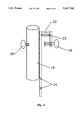
- FIG. 1 shows a rifle and camera attached to a rifle mount beam which is pivotally attached to cylindrical mounting post.
- FIG. 2 shows a tee shaped piece comprising an outer cylinder holder to rotatably hold the cylindrical mounting post with the outer cylinder holder having positioning arm or side arm attached thereto.
- FIG. 3 shows a positioning armholder to slidably fit over the positioning arm and a cylindrical post attached at right angles to the positioning arm holder.
- FIG. 4 shows a clamp to movable fasten to a fixed position rail; with the clamp attached to an open cylindrical holder sized to hold the cylindrical post which is attached to the positioning arm holder as shown in FIG. 3.
- FIG. 5 shows detail of a pivotal connection and locking pin to allow adjustably fixing the rifle in a horizontal position.
- FIG. 6 shows a camera and camera mount attachable to the rifle mount beam.
- FIG. 7 shows a mounting base to hold the pivotally and vertically adjustable unit shown in FIG. 1 when a hunter is not hunting from a stand or vehicle.
- FIG. 1 we show a rifle 1 held in mounting units 7 with tie down straps 11 that conveniently may be made from VelcroTM.
- the mounting units 7 may be attached to the mounting beam 9 which has a U shaped cross section as shown in FIG. 6.
- camera mount unit 20 Also removably attached to mounting beam 9 is camera mount unit 20.
- the pivot locking knob 21 may be used to hold the mounting unit 20 with camera 25 to the beam 9 in an adjustable fashion.
- a pivotal or horizontal adjustment connector 8 is pivotally connected to cylindrical post 2 with a threaded locking pivot pin 5.
- An adjustment knob 4 with gear teeth meshing with gear teeth 15 on adjustment connector 8 as shown in more detail in FIG. 5 may be adjusted to firmly but movably hold mount 9 and locking pivot pin 5 can be further tightened to hold mount 9 quite rigidly at a desired position.
- a slidable collar 3 with a position locking thumbscrew 6 may be moved and locked in position to adjust the vertical height of beam 9 when the cylindrical mounting post 2 is slipped into outer mounting cylinder 12, as shown in FIG. 2.
- FIG. 2 shows the tee shaped open cylindrical outer mount holder 12 and a side arm 13 with slot 33 which acts to hold the open cylindrical mount 12 in a vertical position as side arm 13 slides into side arm holder 16, FIG. 3, with slot 33 fitting closely around guide pins 32, FIG. 3.
- the side arm 13 is sized to fit closely but to slide easily in side arm holder 16, FIG. 3.
- Locking ring 30 is held in place with a threaded thumb screw 31 to prevent arm 31 from disengaging from side arm holder 16.
- FIG. 3 we show side arm holder 16 rigidly attached at right angles to a cylindrical post 14.
- Cylindrical post 14 is sized to fit closely but rotatably in the inner cylindrical holder 19, FIG. 4.
- Thumbscrew 35 may be used to lock cylindrical post 14 in position when desired.
- post 2 In one preferred embodiment post 2, FIG. 1, cylindrical holder 12, FIG. 2, cylindrical post 14, FIG. 3, and inner cylindrical holder 19 all may be approximately 12" long and 3/4 to 2 inches in diameter.
- Side arm 13 is preferably about 18 to 24 inches long with side arm holder 16 being 6" to 12" in length.
- FIG. 4 we show a U shaped clamp 22 preferably made of about 1/4" thick steel with a shorter leg of the clamp having a locking screw with knob 18 to fasten clamp 22 to a metal or wooden rail.
- the longer leg of the U shaped clamp has an open inner cylindrical mounting cylinder 19 which may be rigidly attached thereto with bolts or by brazing or welding with welding being preferred. Hardened aluminum is the preferred construction material and it may be brazed to steel clamp 22.
- openings 34 are provided to allow fastening the lower end of the longer leg of U shaped clamp 22 to a structural support as may be installed in a vehicle or the side of a wooden deer blind.
- a minimum of two roller bearings 23 allow loosening of knob 18 in order that the clamp assembly 22 may be slidably moved.
- FIG. 5 we show a detail of one type of pivotal connection of mounting post 2 to the horizontal adjustment connector 8 which is attached to mounting beam 9.
- a flat upper end of mounting post 2 may be approximately 3/8" wide and 4" long with a top opening to admit locking pin 5 to hold post 2 pivotally connected to connector 8 which may be brazed, welded or screw mounted in the underside of mounting beam 9.
- a geared knob 4 is pivotally attached to mounting post 2 and positioned for the gears on knob 4 to engage gears 15 on the horizontal adjustment connector 8 to allow smooth adjustment of horizontal level of the rifle in mounting beam 9
- VelcroTM tie-down straps 11 to hold a rifle in mounts 7 on mounting beam 9 are preferred but other fastening means would be suitable.
- FIG. 6 one preferred type of camera mount 21 is shown to allow removable and adjustable attachment to mounting beam 9 with a threaded locking screw 20.
- Camera 25 may attached in an adjustable fashion with a threaded bolt in knob 26 going through holder 21 into a threaded opening normally found in cameras for a tripod mount. Camera 25 could also be fastened to holder 21 with VelcroTM straps (not shown).
- FIG. 7 we show a mounting unit 25 designed to be carried by a hunter in his pocket and set up when he wishes to hunt in a sitting position outside of a deer stand or vehicle.
- Unit 37 has an opening 28 to rotatably hold post 2, FIG. 1 and has three extensible legs 27 that may be carried folded together in a shortened position and are connected with connectors 26 to allow the legs 27 to be spread to a limited position.
- a hunter With the unit as shown in FIG. 1 slipped into unit 25 a hunter has a solid shooting position allowing a swinging and horizontal adjustment of mounting beam 9, FIG. 1.
- cylindrical post 2 of FIG. 1 may be fitted into inner cylindrical holder 19 to give a simpler assembly useable in more limited space than the more complex assembly described under the preferred embodiment.
- a minor purpose is to allow the user to carry a tripod mount to allow a swinging motion with horizontal adjustment using a removable portion of the mechanism as described in the drawings.
Abstract
A combination of a camera mount and a gun mount allowing horizontal, vertical and positional adjustment with manually activated locking knobs allowing comfortable multidirectional shooting with a gun that may be rigidly clamped in any one of a multiplicity of rapidly adjustable positions and with the camera adjustably mounted allowing a hunter to take a picture instead using the gun.
Description
In this country the hunting sport continues to grow along with the population of some larger game such as deer. With eradication of screw worm and hunting of deer largely limited to harvesting of bucks or male deer, the deer population not only grows in one locality but continues to spread. Individual hunters are normally limited to harvesting no more than two bucks in one season and therefore frequently enjoy seeing but not shooting a particular buck while waiting for a larger or trophy animal.
There is a desire to aid the hunter in making certain that he makes a clean kill and does not wound the animal. There is also a desire on the part of many hunters to be able to take pictures of various animals that he sees but is not hunting or does not wish to shoot. A hunter sitting quietly in a hunting stand sees and enjoys seeing a wide variety of animals.
The multi-functional variable position rifle and camera mount fills the desire of the hunter not only to make almost perfect shots, but also to take pictures instead of shooting. A secondary function of the device is to allow adjusting the scope or telescopic sights on a rifle before hunting by calibrating or adjusting the scope for a distance as chosen by the hunter. Most commonly, the telescopic sights on larger rifles are calibrated to hit a bulls eye on a target at 100 or 200 yards. Many minor mechanical details may be easily changed in the invention as described and we wish to be limited only to the general purpose and description in these claims, drawings, and specifications.
The objective of this invention includes:
a) having a mounting beam for a rifle and/or a camera with a clamp or mounting device suitable for rigid attachment to a hunting stand or hunting vehicle and with movable mechanism to allow a hunter to comfortably aim and rapidly lock the rifle or camera in any one of many positions.
b) having a rifle mount allowing both surveying and horizontal adjustment that may slide into a holder with extensible legs with the holder sized to be carried in a hunter's pocket.
c) having clamping mechanisms that allow rapid clamping of the rifle and the movable parts of the device in a fixed position thereby allowing essentially perfect shooting. The preferred embodiment of the invention may be described as five major components. These are:
1) a rifle and camera mounting beam with means to adjustably fasten a rifle and/or camera to the mounting beam.
2) a cylindrical mounting post that pivotally attaches to the mounting beam and has a locking device to lock the beam in a desired position and a slidable collar that may be locked in position on the mounting post;
3) an outer mounting open cylinder attached at right angles to a cylindrical side arm or horizontal positioning arm; the outer mounting cylinder being sized to closely but slidably fit over the cylindrical mounting post with the sliding collar on the cylindrical mounting post being used to adjust the vertical height of the gun mounting beam above the outer mounting open cylinder and allowing the mounting post to be rotated in the outer mounting open cylinder;
4) a tee shaped mounting piece comprising an open cylinder sized to closely but slidably fit the horizontal positioning arm and attached at right angles to a cylindrical pivot post.
5) a U shaped clamp with a threaded thumb screw or similar locking device in one leg of the U shaped clamp to allow the clamp to move easily and be fastened rigidly to a rail such as found in a deer blind or as may be installed on a vehicle and an open inner mounting cylinder attached to the other leg of the U shaped clamp; the open inner mounting cylinder is sized to closely but slidably fit over the cylindrical pivot post of the tee shaped mounting piece.
To assemble for use the U shaped clamp with the open inner mounting cylinder is clamped to a rail or horizontal support piece. The cylindrical pivot post of the tee shaped mounting piece is slipped into the inner open mounting cylinder. The horizontal positioning arm or side arm of the outer mounting cylinder is slipped into the horizontal open cylinder of the tee shaped mounting piece. The cylindrical mounting post, which is attached to the mounting beam, is slipped into the outer mounting cylinder and the rifle and/or camera are fastened to the mounting beam. All pieces may be rigidly attached to each other by tightening thumb screws or similar locking devices in the inner mounting cylinder, the open cylinder holding the positioning arm and the inner mounting cylinder. The mounting beam may be held horizontal with a threaded locking device in the cylindrical mounting post. With the mount assembled as indicated a hunter may adjust the vertical height of the mounting post. The hunter may then move the gun in a natural movement and lock the gun or camera in a given position as he wishes. The many different positions are made possible because the side armor positioning arm can both pivot and slide in or out thereby allowing a range of positions of the inner mount that allows the rifle to be pivoted while the pivotal connection between the rifle mount allows tilting the rifle to make either a very close or long shot. Further flexibility is attained by installing one or more roller bearings in the short section of the U shaped clamp thereby allowing the clamp to move easily on a support rail before clamping rigidly to the support rail.
We've described a preferred embodiment of the unit as made essentially from sections of open pipe; however, one skilled in the art could make mechanical modifications to allow similar clamping and movement of the rifle and camera, we therefore do not wish to be limited to exact details, but only as to general spirit and purpose as outlined in these claims and specifications.
FIG. 1 shows a rifle and camera attached to a rifle mount beam which is pivotally attached to cylindrical mounting post.
FIG. 2 shows a tee shaped piece comprising an outer cylinder holder to rotatably hold the cylindrical mounting post with the outer cylinder holder having positioning arm or side arm attached thereto.
FIG. 3 shows a positioning armholder to slidably fit over the positioning arm and a cylindrical post attached at right angles to the positioning arm holder.
FIG. 4 shows a clamp to movable fasten to a fixed position rail; with the clamp attached to an open cylindrical holder sized to hold the cylindrical post which is attached to the positioning arm holder as shown in FIG. 3.
FIG. 5 shows detail of a pivotal connection and locking pin to allow adjustably fixing the rifle in a horizontal position.
FIG. 6 shows a camera and camera mount attachable to the rifle mount beam.
FIG. 7 shows a mounting base to hold the pivotally and vertically adjustable unit shown in FIG. 1 when a hunter is not hunting from a stand or vehicle.
A preferred embodiment of the invention may best be described by reference to the drawings.
In FIG. 1 we show a rifle 1 held in mounting units 7 with tie down straps 11 that conveniently may be made from Velcro™. The mounting units 7 may be attached to the mounting beam 9 which has a U shaped cross section as shown in FIG. 6. Also removably attached to mounting beam 9 is camera mount unit 20. The pivot locking knob 21 may be used to hold the mounting unit 20 with camera 25 to the beam 9 in an adjustable fashion.
A pivotal or horizontal adjustment connector 8 is pivotally connected to cylindrical post 2 with a threaded locking pivot pin 5. An adjustment knob 4 with gear teeth meshing with gear teeth 15 on adjustment connector 8 as shown in more detail in FIG. 5 may be adjusted to firmly but movably hold mount 9 and locking pivot pin 5 can be further tightened to hold mount 9 quite rigidly at a desired position.
A slidable collar 3 with a position locking thumbscrew 6 may be moved and locked in position to adjust the vertical height of beam 9 when the cylindrical mounting post 2 is slipped into outer mounting cylinder 12, as shown in FIG. 2.
FIG. 2 shows the tee shaped open cylindrical outer mount holder 12 and a side arm 13 with slot 33 which acts to hold the open cylindrical mount 12 in a vertical position as side arm 13 slides into side arm holder 16, FIG. 3, with slot 33 fitting closely around guide pins 32, FIG. 3. The side arm 13 is sized to fit closely but to slide easily in side arm holder 16, FIG. 3. Locking ring 30 is held in place with a threaded thumb screw 31 to prevent arm 31 from disengaging from side arm holder 16.
In FIG. 3 we show side arm holder 16 rigidly attached at right angles to a cylindrical post 14. Cylindrical post 14 is sized to fit closely but rotatably in the inner cylindrical holder 19, FIG. 4. Thumbscrew 35 may be used to lock cylindrical post 14 in position when desired.
In one preferred embodiment post 2, FIG. 1, cylindrical holder 12, FIG. 2, cylindrical post 14, FIG. 3, and inner cylindrical holder 19 all may be approximately 12" long and 3/4 to 2 inches in diameter. Side arm 13 is preferably about 18 to 24 inches long with side arm holder 16 being 6" to 12" in length.
In FIG. 4 we show a U shaped clamp 22 preferably made of about 1/4" thick steel with a shorter leg of the clamp having a locking screw with knob 18 to fasten clamp 22 to a metal or wooden rail. The longer leg of the U shaped clamp has an open inner cylindrical mounting cylinder 19 which may be rigidly attached thereto with bolts or by brazing or welding with welding being preferred. Hardened aluminum is the preferred construction material and it may be brazed to steel clamp 22. Although normally not needed, openings 34 are provided to allow fastening the lower end of the longer leg of U shaped clamp 22 to a structural support as may be installed in a vehicle or the side of a wooden deer blind. A minimum of two roller bearings 23 allow loosening of knob 18 in order that the clamp assembly 22 may be slidably moved.
In FIG. 5 we show a detail of one type of pivotal connection of mounting post 2 to the horizontal adjustment connector 8 which is attached to mounting beam 9. A flat upper end of mounting post 2 may be approximately 3/8" wide and 4" long with a top opening to admit locking pin 5 to hold post 2 pivotally connected to connector 8 which may be brazed, welded or screw mounted in the underside of mounting beam 9. A geared knob 4 is pivotally attached to mounting post 2 and positioned for the gears on knob 4 to engage gears 15 on the horizontal adjustment connector 8 to allow smooth adjustment of horizontal level of the rifle in mounting beam 9 Velcro™ tie-down straps 11 to hold a rifle in mounts 7 on mounting beam 9 are preferred but other fastening means would be suitable.
In FIG. 6 one preferred type of camera mount 21 is shown to allow removable and adjustable attachment to mounting beam 9 with a threaded locking screw 20. Camera 25 may attached in an adjustable fashion with a threaded bolt in knob 26 going through holder 21 into a threaded opening normally found in cameras for a tripod mount. Camera 25 could also be fastened to holder 21 with Velcro™ straps (not shown).
In FIG. 7 we show a mounting unit 25 designed to be carried by a hunter in his pocket and set up when he wishes to hunt in a sitting position outside of a deer stand or vehicle. Unit 37 has an opening 28 to rotatably hold post 2, FIG. 1 and has three extensible legs 27 that may be carried folded together in a shortened position and are connected with connectors 26 to allow the legs 27 to be spread to a limited position. With the unit as shown in FIG. 1 slipped into unit 25 a hunter has a solid shooting position allowing a swinging and horizontal adjustment of mounting beam 9, FIG. 1.
In a second embodiment of the invention, cylindrical post 2 of FIG. 1 may be fitted into inner cylindrical holder 19 to give a simpler assembly useable in more limited space than the more complex assembly described under the preferred embodiment.
The above descriptions are of preferred embodiments but differing shapes, differing pieces and differing clamping means could be used to accomplish the major purpose of this design which may be described as holding a rifle and/or camera in a removable, fixed position with mechanism to:
1) allow a swinging motion about a pivot point;
2) allow a forward and backward motion;
3) allow a height adjustment to accommodate users of differing heights;
4) allow moving the pivot point thereby allowing a wider range of swinging motions;
5) allow horizontal adjustments with hand operated mechanisms;
6) to have available manually operable locking mechanism to hold the rifle and/or camera in a fixed position when the rifle is sighted on target. A minor purpose is to allow the user to carry a tripod mount to allow a swinging motion with horizontal adjustment using a removable portion of the mechanism as described in the drawings.
Claims (6)
1. A multi-functional variable position rifle and camera mount comprising:
a) a base plate clamp means and an inner cylindrical holder attached thereto;
b) a threaded manually operable lock pin means in said inner cylindrical holder;
c) a rifle mounting beam, a horizontal adjustment connector means and a cylindrical mounting post with said cylindrical mounting post pivotally attached to said horizontal adjustment connector means with said horizontal adjustment connector means attached to said rifle mounting beam and with said cylindrical mounting post sized to slidably fit into said inner cylindrical holder and to be movably and adjustably held at a vertical position using a threaded thumbscrew in a slidable collar on said cylindrical mounting post;
d) a locking means in said horizontal adjustment connector means to allow manual locking of said horizontal adjustment connector means in a fixed position;
e) a pair of rifle mounts and tie down means attached to said rifle mounting beam to allow fastening a rifle rigidly in said rifle mounts.
2. A multi-functional variable position rifle and camera mount as in claim 1 wherein said base plate clamp means comprises:
a) a U shaped base with a manually operable means to fasten said clamp to a fixed rail in one leg and with said inner cylindrical holder rigidly attached in a second leg;
b) dual roller means inside said U shaped base to allow said base clamp means to move smoothly on said rail with said manually operable fastening means allowing fastening said clamp means in a fixed position.
3. A multi-functional variable position rifle and camera mount comprising:
a) a base plate clamp means and inner cylindrical holder attached thereto;
b) a threaded manually operable lock pin means in said cylindrical holder;
c) a T shaped swivel piece with a pivot post sized to fit movably in said inner cylindrical holder and an open positioning cylinder with guide pins through the side wall with said open positioning cylinder mounted at right angles to an upper end of said pivot post;
c) an outer mounting cylinder with a manually operable locking screw rigidly attached at right angles to a slotted arm sized to movably slide into said open positioning cylinder with said slot sliding over said guide pins;
d) a cylindrical post sized to fit movably into said outer mounting cylinder;
e) a slidable collar means with a locking thumbscrew to fit over said cylindrical post and allow positional adjustment of said cylindrical post in said outer mounting cylinder;
f) a horizontal adjustment connector means pivotally attached to a top end of said cylindrical post with a geared knob mounted to said cylindrical post and interacting with gear teeth on said connector means;
g) a mounting beam means rigidly attached to said horizontal adjustment connector means;
h) dual rifle mounts with means to removably hold a rifle in said dual mounts; said dual mounts being rigidly attached to said mounting beam means.
4. A multi-functional variable position rifle and camera mount comprising:
a) a base plate clamp means and inner cylindrical holder attached thereto;
b) a threaded manually operable lock pin means in said inner cylindrical holder;
c) a T shaped swivel piece with a pivot post sized to fit movably in said inner cylindrical holder and an open positioning cylinder with guide pins through the side wall with said open positioning cylinder mounted at right angles to an upper end of said pivot post;
c) an outer mounting cylinder with a manually operable locking screw rigidly attached at right angles to a slotted arm sized to movably slide into said open positioning cylinder with said slot sliding over said guide pins;
d) a cylindrical post sized to fit movably into said outer mounting cylinder;
e) a slidable collar means with a locking thumbscrew to fit over said cylindrical post and allow positional adjustment of said cylindrical post in said outer mounting cylinder;
f) a horizontal adjustment connector means pivotally attached to a top end of said cylindrical post with a geared knob mounted to said cylindrical post and interacting with gear teeth on said connector means;
g) a mounting beam means rigidly attached to said horizontal adjustment connector means;
h) dual rifle mounts with means to removably hold a rifle in said dual mounts, said dual mounts being rigidly attached to said mounting beam means;
i) a positionally adjustable camera mount attached to said mounting beam means.
5. A multi-functional variable position rifle and camera mount comprising:
a) a mounting beam, a rifle mount means, and a positionally adjustable camera mount means; said rifle mount means being attached to said mounting beam and acting to rigidly but removably hold a rifle in said mount means and said camera mount means being attached to said mounting beam and acting to removably hold a camera in said positionally adjustable camera mount means;
b) a cylindrical mounting post pivotally attached to said mounting beam;
c) a horizontal adjustment means and a locking means to adjust and lock said cylindrical mounting post and said mounting beam in a fixed position relative to each other;
d) a clamp, an outer mounting open cylinder with a side arm, a side arm holder attached to a cylindrical post, and an inner open mounting cylinder cooperating to make a fixed position swivel joint by sliding said cylindrical post attached to said arm holder into said inner open mounting cylinder and to make a moveable position outer swivel connection by sliding said cylindrical mounting post, which is pivotally attached to said mounting beam, into said outer mounting cylinder and sliding said arm into said side arm holder.
6. A multi-functional variable position rifle and camera mount as in claim 5 wherein said inner mounting open cylinder, said outer mounting cylinder and said side arm holder are each equipped with manually adjustable means to allow holding said mounting post in a fixed position in said outer mounting cylinder and to allow holding said arm in a fixed position in said side arm holder and to allow holding said cylindrical post attached to said side arm holder in a fixed position in said inner mounting open cylinder.
Priority Applications (2)
| Application Number | Priority Date | Filing Date | Title |
|---|---|---|---|
| US07/898,830 US5347740A (en) | 1992-06-15 | 1992-06-15 | Multi-functional variable position rifle and camera mount |
| US08/279,011 US5491919A (en) | 1992-06-15 | 1994-07-22 | Multi-functional variable position rifle and camera mount |
Applications Claiming Priority (1)
| Application Number | Priority Date | Filing Date | Title |
|---|---|---|---|
| US07/898,830 US5347740A (en) | 1992-06-15 | 1992-06-15 | Multi-functional variable position rifle and camera mount |
Related Child Applications (1)
| Application Number | Title | Priority Date | Filing Date |
|---|---|---|---|
| US08/279,011 Continuation-In-Part US5491919A (en) | 1992-06-15 | 1994-07-22 | Multi-functional variable position rifle and camera mount |
Publications (1)
| Publication Number | Publication Date |
|---|---|
| US5347740A true US5347740A (en) | 1994-09-20 |
Family
ID=25410092
Family Applications (1)
| Application Number | Title | Priority Date | Filing Date |
|---|---|---|---|
| US07/898,830 Expired - Lifetime US5347740A (en) | 1992-06-15 | 1992-06-15 | Multi-functional variable position rifle and camera mount |
Country Status (1)
| Country | Link |
|---|---|
| US (1) | US5347740A (en) |
Cited By (89)
| Publication number | Priority date | Publication date | Assignee | Title |
|---|---|---|---|---|
| US5481817A (en) * | 1993-10-18 | 1996-01-09 | Parker; Michael A. | Firearm support |
| US5491919A (en) * | 1992-06-15 | 1996-02-20 | Rather; Lewis L. | Multi-functional variable position rifle and camera mount |
| US5589903A (en) * | 1994-07-20 | 1996-12-31 | Lino Manfrotto & Co., S.P.A. | Panorama head for optical equipment particularly for photographic equipment |
| US5913668A (en) * | 1998-01-02 | 1999-06-22 | Messer; Jerry Wayne | Weapon rest |
| US5933999A (en) * | 1998-07-09 | 1999-08-10 | Mcclure; John H. | Gun rest |
| US5937560A (en) * | 1997-12-02 | 1999-08-17 | B-5, Inc. | Adjustable fire arm support |
| US5979099A (en) * | 1998-04-29 | 1999-11-09 | Kervin; Durham L. | Truck mountable shooting rest |
| US6000163A (en) * | 1998-04-03 | 1999-12-14 | Gordon; Terry | Photographic rifle scope apparatus and method |
| US6042080A (en) * | 1996-11-21 | 2000-03-28 | Shepherd; Thomas Jefferson | Multi-purpose rest having magnetic base |
| US6044747A (en) * | 1998-04-06 | 2000-04-04 | Felts; Jeffrey G. | Sharpshooters rifle rest |
| US6058641A (en) * | 1998-09-29 | 2000-05-09 | Vecqueray; Richard C. | Pivotable bench rest for shooting a firearm |
| US6272785B1 (en) | 1999-07-08 | 2001-08-14 | Jerry M. Mika | Gun holder |
| US6338218B1 (en) * | 1999-11-16 | 2002-01-15 | Sam J. Hegler | Apparatus for supporting a firearm |
| US6363223B1 (en) | 2000-03-29 | 2002-03-26 | Terry Gordon | Photographic firearm apparatus and method |
| US20020040544A1 (en) * | 2000-06-15 | 2002-04-11 | Muhlestein Todd J. | Firearm leveler and stabilizer |
| US6574899B1 (en) | 2002-02-07 | 2003-06-10 | Thomas Mostello | Tripod-mounted combined gun rest and armrest |
| US20030205599A1 (en) * | 2002-05-01 | 2003-11-06 | Brown Michael S. | Transportable shooting apparatus |
| US20040020097A1 (en) * | 2002-08-02 | 2004-02-05 | Deros Mark A. | Adjustable gun rest apparatus |
| US6729592B1 (en) | 2001-04-24 | 2004-05-04 | Russell Kurtts | Highly adjustable support for optical devices |
| US20040134113A1 (en) * | 2002-08-02 | 2004-07-15 | Deros Mark A. | Adjustable gun rest apparatus |
| US20050018041A1 (en) * | 2003-07-21 | 2005-01-27 | Towery Clay E. | Electronic firearm sight, and method of operating same |
| US6860055B1 (en) | 2004-08-26 | 2005-03-01 | Ligi Tool And Engineering, Inc. | Adjustable rifle support |
| US6895709B1 (en) | 2002-04-30 | 2005-05-24 | Gary L. Krien | Portable seat and platform support |
| US20050109891A1 (en) * | 2003-11-26 | 2005-05-26 | Mccuskey Scott A. | Weapon caddy |
| US6913286B2 (en) | 2002-04-26 | 2005-07-05 | Kwik Tek, Inc. | Multi-purpose adjustable carrier for all-terrain vehicles |
| US20050213962A1 (en) * | 2000-03-29 | 2005-09-29 | Gordon Terry J | Firearm Scope Method and Apparatus for Improving Firing Accuracy |
| US20050252063A1 (en) * | 2004-05-12 | 2005-11-17 | Flannigan Timothy A | Imaging system for optical devices |
| US20050268521A1 (en) * | 2004-06-07 | 2005-12-08 | Raytheon Company | Electronic sight for firearm, and method of operating same |
| US20060086032A1 (en) * | 2004-10-27 | 2006-04-27 | Joseph Valencic | Weapon and input device to record information |
| US20060137235A1 (en) * | 2004-12-23 | 2006-06-29 | Raytheon Company A Corporation Of The State Of Delaware | Method and apparatus for safe operation of an electronic firearm sight depending upon detected ambient illumination |
| US7100318B1 (en) | 2004-05-24 | 2006-09-05 | Kasey Dallas Beltz | Adjustable firearm support |
| US20060225335A1 (en) * | 2004-12-23 | 2006-10-12 | Raytheon Company A Corporation Of The State Of Delaware | Method and apparatus for safe operation of an electronic firearm sight depending upon the detection of a selected color |
| US7124531B1 (en) | 2004-12-23 | 2006-10-24 | Raytheon Company | Method and apparatus for safe operation of an electronic firearm sight |
| US20070019804A1 (en) * | 2005-06-30 | 2007-01-25 | Kramer Aaron F | Waterproof flip phone case |
| US20070068378A1 (en) * | 2004-09-20 | 2007-03-29 | Endres Steven J | Body mounted weapons platform |
| US20070151550A1 (en) * | 2005-12-31 | 2007-07-05 | Fitting Adam E | Paintball launching device |
| US20080023915A1 (en) * | 2006-02-24 | 2008-01-31 | Battenfeld Technologies, Inc. | Shooting gallery devices and methods |
| US20080116340A1 (en) * | 2006-11-21 | 2008-05-22 | James David Greene | Optic support arm |
| US20080174071A1 (en) * | 2006-02-24 | 2008-07-24 | Battenfeld Technologies, Inc. | Shooting gallery devices and methods |
| US20080263928A1 (en) * | 2007-02-26 | 2008-10-30 | Battenfeld Technologies, Inc. | Firearm supports and gas-assisted methods of filling firearm supports |
| US7475879B1 (en) | 2003-06-02 | 2009-01-13 | Enrique Fernandez | Paintball gaming device, system, and associated methods |
| US20090026679A1 (en) * | 2007-07-25 | 2009-01-29 | Harman Iii James Pope | Adjustable gun vise |
| US20090193702A1 (en) * | 2008-01-31 | 2009-08-06 | Lin Ting-Sheng | Articulating firearm fore grip |
| US7614174B1 (en) | 2005-05-31 | 2009-11-10 | Kasey Dallas Beltz | Bipod firearm support |
| US7654498B1 (en) | 2005-04-23 | 2010-02-02 | Kasey Dallas Beltz | Article support device |
| US20100102178A1 (en) * | 2008-10-27 | 2010-04-29 | Cade Smith | Apparatus and method for clamping |
| US7726478B2 (en) | 2006-02-27 | 2010-06-01 | Battenfeld Technologies, Inc. | Containers for carrying firearm accessories and/or supporting firearms |
| US7774972B2 (en) | 2006-09-11 | 2010-08-17 | Battenfeld Technologies, Inc. | Modular shooting rests and shooting rest assemblies |
| US7779572B2 (en) | 2006-05-08 | 2010-08-24 | Battenfeld Technologies, Inc. | Bipod device for use with a firearm |
| US20100270201A1 (en) * | 2006-02-27 | 2010-10-28 | Battenfeld Technologies, Inc. | Portable storage case with integral stabilizing platform for use with a firearm support |
| US7823317B2 (en) | 2006-08-22 | 2010-11-02 | Battenfeld Technologies, Inc. | Adjustable shooting rests and shooting rest assemblies |
| US7845267B2 (en) | 2007-09-11 | 2010-12-07 | Battenfield Technologies, Inc. | Attachment mechanisms for coupling firearms to supporting structures |
| US20110107643A1 (en) * | 2009-11-06 | 2011-05-12 | Magpul Industries Corporation | Ergonomic Firearm Fore Grip |
| US7946071B2 (en) | 2004-11-10 | 2011-05-24 | Battenfeld Technologies, Inc. | Firearm vise |
| US20110167705A1 (en) * | 2008-11-21 | 2011-07-14 | Battenfeld Technologies, Inc. | Shooting rests with adjustable height assemblies |
| US8011129B2 (en) | 2003-06-13 | 2011-09-06 | Battenfeld Technologies, Inc. | Recoil-reducing shooting rest |
| US20110225788A1 (en) * | 2006-08-21 | 2011-09-22 | Battenfeld Technologies, Inc, | Vibratory tumblers for processing workpieces and methods for packaging and constructing such tumblers |
| US8104212B2 (en) | 2006-02-24 | 2012-01-31 | Battenfeld Technologies, Inc. | Firearm supports, such as shooting bags, and firearm support assemblies |
| US20120180281A1 (en) * | 2010-12-31 | 2012-07-19 | Miller Jason E | Accessory mounting apparatus for a vehicle |
| US8296988B2 (en) | 2006-11-30 | 2012-10-30 | Battenfeld Technologies, Inc. | Firearm supporting devices, methods of assembling firearm supporting devices, and methods of packaging firearm supporting devices |
| US8327570B2 (en) | 2007-05-08 | 2012-12-11 | Battenfeld Technologies, Inc. | Adjustable firearm supports and associated methods of use and manufacture |
| US8336708B2 (en) | 2007-07-20 | 2012-12-25 | Battenfeld Technologies, Inc. | System and container for organizing and carrying tools and tool sets |
| US8371057B2 (en) | 2006-05-09 | 2013-02-12 | Battenfeld Technologies, Inc. | Firearm cleaning apparatus with protective coating |
| CN102957872A (en) * | 2011-08-22 | 2013-03-06 | 无锡海森诺科技有限公司 | Multifunctional photographing device |
| US8402684B1 (en) | 2005-05-31 | 2013-03-26 | Kasey Dallas Beltz | Bipod firearm support |
| US8549786B1 (en) | 2010-12-17 | 2013-10-08 | Todd Griffith | Rifle rest |
| US8621773B2 (en) | 2003-06-13 | 2014-01-07 | Battenfeld Technologies, Inc. | Shooting rests for supporting firearms |
| US8695985B2 (en) | 2011-01-07 | 2014-04-15 | Battenfeld Technologies, Inc. | Stowable shooting target assemblies |
| US8819983B2 (en) | 2010-12-17 | 2014-09-02 | Jeff Tate | Systems, methods, and apparatus for securing a recording device to a hunting apparatus |
| US8894024B2 (en) | 2011-04-27 | 2014-11-25 | Mark A. Deros | Adapter and mechanism for attaching accessories to support structures |
| US20140366423A1 (en) * | 2013-05-13 | 2014-12-18 | Stanley M. Clary | Adjustable Shooting Rail Device |
| US8931201B2 (en) | 2012-12-31 | 2015-01-13 | Battenfeld Technologies, Inc. | Gun support apparatus |
| US20150121741A1 (en) * | 2013-11-01 | 2015-05-07 | Lorne Bowman | Adjustable Firearm Support |
| USD745629S1 (en) | 2014-08-29 | 2015-12-15 | Magpul Industries Corporation | Firearm fore grip |
| US9255751B1 (en) | 2014-01-10 | 2016-02-09 | Kasey Dallas Beltz | Bipod firearm support |
| US9488437B1 (en) | 2014-05-02 | 2016-11-08 | Gideon Schnog | Firearm mounted video camera system |
| US9702653B2 (en) | 2015-10-09 | 2017-07-11 | Battenfeld Technologies, Inc. | Firearm shooting rest |
| US10288987B2 (en) * | 2016-12-09 | 2019-05-14 | Moises H Olmos-Calderon | Tripod accessory clamp |
| US10514225B2 (en) | 2018-01-17 | 2019-12-24 | Battenfeld Technologies, Inc. | Firearm shooting rest |
| US20200054001A1 (en) * | 2018-08-14 | 2020-02-20 | Steven D. LeBire | Universal steady rest system |
| US10571211B2 (en) | 2017-09-13 | 2020-02-25 | Really Right Stuff, Llc | Recoil management system |
| US10578389B2 (en) | 2018-03-06 | 2020-03-03 | Battenfeld Technologies, Inc. | Portable shooting bench |
| US10782085B2 (en) | 2019-02-15 | 2020-09-22 | Aob Products Company | Recoil-reducing firearm shooting rest having tank |
| US10794654B2 (en) | 2018-05-01 | 2020-10-06 | Thomas Burton | Universal pintle mount for a weapon |
| US11085736B2 (en) | 2018-04-27 | 2021-08-10 | Really Right Stuff, Llc | Ball head based clamping device |
| GB2595424A (en) * | 2015-03-20 | 2021-11-24 | 4Th Dimension Dev Pty Ltd | A connector arrangement |
| US20220264058A1 (en) * | 2021-02-18 | 2022-08-18 | United States Of America, As Represented By The Secretary Of The Navy | Device to Capture Video through a Weapon's Iron Sight during Live Fire |
| US11519697B2 (en) * | 2018-04-27 | 2022-12-06 | Cascade Corporation | Lever based clamping device |
| US11841108B2 (en) | 2019-12-17 | 2023-12-12 | Aob Products Company | Multi-legged equipment support having leg angle adjustment |
Citations (17)
| Publication number | Priority date | Publication date | Assignee | Title |
|---|---|---|---|---|
| GB102161A (en) * | 1916-01-07 | 1916-11-23 | William Alfred Roberts | Improvements in Rifle Stands. |
| GB129679A (en) * | 1916-10-10 | 1919-07-24 | Francois Thomas | Improvements in or relating to Mountings for Machine Guns. |
| FR499816A (en) * | 1914-12-03 | 1920-02-24 | Roberto Duina | Apparatus for practicing target shooting with the rifle or carabiner |
| US1547295A (en) * | 1924-03-28 | 1925-07-28 | William R Bull | Machine-gun tripod |
| CH211677A (en) * | 1940-04-02 | 1940-10-15 | Alois Buschor Theodor | Support device for rifles. |
| FR861284A (en) * | 1939-10-31 | 1941-02-05 | Cometal S A R L | Machine gun easel |
| US2282680A (en) * | 1940-07-15 | 1942-05-12 | Chicago Aerial Survey Company | Gun camera |
| US2441874A (en) * | 1942-02-24 | 1948-05-18 | Harold W Evans | Gun mount for land and water vehicles |
| US2664797A (en) * | 1950-08-25 | 1954-01-05 | Chester M Thrasher | Camera gun |
| US3022898A (en) * | 1960-07-15 | 1962-02-27 | Loeb Henry | Gun holder |
| US4393614A (en) * | 1980-06-09 | 1983-07-19 | Pickett Fred E | Gun rest |
| DE3629843A1 (en) * | 1985-12-14 | 1987-06-19 | Johannes Than | Holding and aiming apparatus for hunting |
| US4876814A (en) * | 1989-03-08 | 1989-10-31 | Lombardo Philip C | Gun rest for supporting the buttstock |
| US4913391A (en) * | 1988-08-29 | 1990-04-03 | Klipp Kenneth W | Sportsman's gun rest and object holder |
| US4937965A (en) * | 1989-05-23 | 1990-07-03 | Salvador Narvaez | Adjustable gun rest |
| US5060410A (en) * | 1990-07-13 | 1991-10-29 | Evan Mueller | Collapsible shooting stand |
| US5073788A (en) * | 1990-07-06 | 1991-12-17 | Lingwall David F | Camera support |
-
1992
- 1992-06-15 US US07/898,830 patent/US5347740A/en not_active Expired - Lifetime
Patent Citations (17)
| Publication number | Priority date | Publication date | Assignee | Title |
|---|---|---|---|---|
| FR499816A (en) * | 1914-12-03 | 1920-02-24 | Roberto Duina | Apparatus for practicing target shooting with the rifle or carabiner |
| GB102161A (en) * | 1916-01-07 | 1916-11-23 | William Alfred Roberts | Improvements in Rifle Stands. |
| GB129679A (en) * | 1916-10-10 | 1919-07-24 | Francois Thomas | Improvements in or relating to Mountings for Machine Guns. |
| US1547295A (en) * | 1924-03-28 | 1925-07-28 | William R Bull | Machine-gun tripod |
| FR861284A (en) * | 1939-10-31 | 1941-02-05 | Cometal S A R L | Machine gun easel |
| CH211677A (en) * | 1940-04-02 | 1940-10-15 | Alois Buschor Theodor | Support device for rifles. |
| US2282680A (en) * | 1940-07-15 | 1942-05-12 | Chicago Aerial Survey Company | Gun camera |
| US2441874A (en) * | 1942-02-24 | 1948-05-18 | Harold W Evans | Gun mount for land and water vehicles |
| US2664797A (en) * | 1950-08-25 | 1954-01-05 | Chester M Thrasher | Camera gun |
| US3022898A (en) * | 1960-07-15 | 1962-02-27 | Loeb Henry | Gun holder |
| US4393614A (en) * | 1980-06-09 | 1983-07-19 | Pickett Fred E | Gun rest |
| DE3629843A1 (en) * | 1985-12-14 | 1987-06-19 | Johannes Than | Holding and aiming apparatus for hunting |
| US4913391A (en) * | 1988-08-29 | 1990-04-03 | Klipp Kenneth W | Sportsman's gun rest and object holder |
| US4876814A (en) * | 1989-03-08 | 1989-10-31 | Lombardo Philip C | Gun rest for supporting the buttstock |
| US4937965A (en) * | 1989-05-23 | 1990-07-03 | Salvador Narvaez | Adjustable gun rest |
| US5073788A (en) * | 1990-07-06 | 1991-12-17 | Lingwall David F | Camera support |
| US5060410A (en) * | 1990-07-13 | 1991-10-29 | Evan Mueller | Collapsible shooting stand |
Cited By (136)
| Publication number | Priority date | Publication date | Assignee | Title |
|---|---|---|---|---|
| US5491919A (en) * | 1992-06-15 | 1996-02-20 | Rather; Lewis L. | Multi-functional variable position rifle and camera mount |
| US5481817A (en) * | 1993-10-18 | 1996-01-09 | Parker; Michael A. | Firearm support |
| US5589903A (en) * | 1994-07-20 | 1996-12-31 | Lino Manfrotto & Co., S.P.A. | Panorama head for optical equipment particularly for photographic equipment |
| US6042080A (en) * | 1996-11-21 | 2000-03-28 | Shepherd; Thomas Jefferson | Multi-purpose rest having magnetic base |
| US5937560A (en) * | 1997-12-02 | 1999-08-17 | B-5, Inc. | Adjustable fire arm support |
| US5913668A (en) * | 1998-01-02 | 1999-06-22 | Messer; Jerry Wayne | Weapon rest |
| US6000163A (en) * | 1998-04-03 | 1999-12-14 | Gordon; Terry | Photographic rifle scope apparatus and method |
| US6044747A (en) * | 1998-04-06 | 2000-04-04 | Felts; Jeffrey G. | Sharpshooters rifle rest |
| US5979099A (en) * | 1998-04-29 | 1999-11-09 | Kervin; Durham L. | Truck mountable shooting rest |
| US5933999A (en) * | 1998-07-09 | 1999-08-10 | Mcclure; John H. | Gun rest |
| US6058641A (en) * | 1998-09-29 | 2000-05-09 | Vecqueray; Richard C. | Pivotable bench rest for shooting a firearm |
| US6272785B1 (en) | 1999-07-08 | 2001-08-14 | Jerry M. Mika | Gun holder |
| US6338218B1 (en) * | 1999-11-16 | 2002-01-15 | Sam J. Hegler | Apparatus for supporting a firearm |
| US6792206B2 (en) | 2000-03-29 | 2004-09-14 | Terry Gordon | Photographic firearm apparatus and method |
| US6363223B1 (en) | 2000-03-29 | 2002-03-26 | Terry Gordon | Photographic firearm apparatus and method |
| US7194204B2 (en) | 2000-03-29 | 2007-03-20 | Gordon Terry J | Photographic firearm apparatus and method |
| US6580876B1 (en) | 2000-03-29 | 2003-06-17 | Terry Gordon | Photographic firearm apparatus and method |
| US20030180038A1 (en) * | 2000-03-29 | 2003-09-25 | Terry Gordon | Photographic firearm apparatus and method |
| US20050213962A1 (en) * | 2000-03-29 | 2005-09-29 | Gordon Terry J | Firearm Scope Method and Apparatus for Improving Firing Accuracy |
| US20050002668A1 (en) * | 2000-03-29 | 2005-01-06 | Mr. Terry Gordon | Photographic Firearm Apparatus and Method |
| US6772549B2 (en) | 2000-06-15 | 2004-08-10 | Todd J. Muhlestein | Firearm leveler and stabilizer |
| US20020040544A1 (en) * | 2000-06-15 | 2002-04-11 | Muhlestein Todd J. | Firearm leveler and stabilizer |
| US6729592B1 (en) | 2001-04-24 | 2004-05-04 | Russell Kurtts | Highly adjustable support for optical devices |
| US6574899B1 (en) | 2002-02-07 | 2003-06-10 | Thomas Mostello | Tripod-mounted combined gun rest and armrest |
| US6913286B2 (en) | 2002-04-26 | 2005-07-05 | Kwik Tek, Inc. | Multi-purpose adjustable carrier for all-terrain vehicles |
| US20050183320A1 (en) * | 2002-04-30 | 2005-08-25 | Krien Gary L. | Portable seat and platform support |
| US20070124981A1 (en) * | 2002-04-30 | 2007-06-07 | Krien David A | Portable seat and platform support |
| US6895709B1 (en) | 2002-04-30 | 2005-05-24 | Gary L. Krien | Portable seat and platform support |
| US7168199B2 (en) | 2002-04-30 | 2007-01-30 | Krien Gary L | Portable seat and platform support |
| US20030205599A1 (en) * | 2002-05-01 | 2003-11-06 | Brown Michael S. | Transportable shooting apparatus |
| US7066365B2 (en) * | 2002-05-01 | 2006-06-27 | Brown Michael S | Transportable shooting apparatus |
| US20040134113A1 (en) * | 2002-08-02 | 2004-07-15 | Deros Mark A. | Adjustable gun rest apparatus |
| US7086192B2 (en) | 2002-08-02 | 2006-08-08 | Deros Mark A | Adjustable gun rest apparatus |
| US20040020097A1 (en) * | 2002-08-02 | 2004-02-05 | Deros Mark A. | Adjustable gun rest apparatus |
| US7475879B1 (en) | 2003-06-02 | 2009-01-13 | Enrique Fernandez | Paintball gaming device, system, and associated methods |
| US9151561B2 (en) | 2003-06-13 | 2015-10-06 | Battenfeld Technologies, Inc. | Shooting rests for supporting firearms |
| US8621773B2 (en) | 2003-06-13 | 2014-01-07 | Battenfeld Technologies, Inc. | Shooting rests for supporting firearms |
| US10317162B2 (en) | 2003-06-13 | 2019-06-11 | Battenfeld Technologies, Inc. | Shooting rests for supporting firearms |
| US10859336B2 (en) | 2003-06-13 | 2020-12-08 | Aob Products Company | Shooting rests for supporting firearms |
| US8011129B2 (en) | 2003-06-13 | 2011-09-06 | Battenfeld Technologies, Inc. | Recoil-reducing shooting rest |
| US7292262B2 (en) | 2003-07-21 | 2007-11-06 | Raytheon Company | Electronic firearm sight, and method of operating same |
| US20050018041A1 (en) * | 2003-07-21 | 2005-01-27 | Towery Clay E. | Electronic firearm sight, and method of operating same |
| US20050109891A1 (en) * | 2003-11-26 | 2005-05-26 | Mccuskey Scott A. | Weapon caddy |
| US7165750B2 (en) | 2003-11-26 | 2007-01-23 | Mccuskey Scott A | Weapon caddy |
| US20050252063A1 (en) * | 2004-05-12 | 2005-11-17 | Flannigan Timothy A | Imaging system for optical devices |
| US7100318B1 (en) | 2004-05-24 | 2006-09-05 | Kasey Dallas Beltz | Adjustable firearm support |
| US20050268521A1 (en) * | 2004-06-07 | 2005-12-08 | Raytheon Company | Electronic sight for firearm, and method of operating same |
| US6860055B1 (en) | 2004-08-26 | 2005-03-01 | Ligi Tool And Engineering, Inc. | Adjustable rifle support |
| US20070068378A1 (en) * | 2004-09-20 | 2007-03-29 | Endres Steven J | Body mounted weapons platform |
| US7290366B2 (en) * | 2004-09-20 | 2007-11-06 | Endres Steven J | Body mounted weapons platform |
| US20060086032A1 (en) * | 2004-10-27 | 2006-04-27 | Joseph Valencic | Weapon and input device to record information |
| US8578645B2 (en) | 2004-11-10 | 2013-11-12 | Battenfeld Technologies, Inc. | Firearm vise |
| US7946071B2 (en) | 2004-11-10 | 2011-05-24 | Battenfeld Technologies, Inc. | Firearm vise |
| US20060248777A1 (en) * | 2004-12-23 | 2006-11-09 | Raytheon Company A Corporation Of The State Of Delaware | Method and apparatus for safe operation of an electronic firearm sight |
| US7124531B1 (en) | 2004-12-23 | 2006-10-24 | Raytheon Company | Method and apparatus for safe operation of an electronic firearm sight |
| US7121036B1 (en) | 2004-12-23 | 2006-10-17 | Raytheon Company | Method and apparatus for safe operation of an electronic firearm sight depending upon the detection of a selected color |
| US20060225335A1 (en) * | 2004-12-23 | 2006-10-12 | Raytheon Company A Corporation Of The State Of Delaware | Method and apparatus for safe operation of an electronic firearm sight depending upon the detection of a selected color |
| US20060137235A1 (en) * | 2004-12-23 | 2006-06-29 | Raytheon Company A Corporation Of The State Of Delaware | Method and apparatus for safe operation of an electronic firearm sight depending upon detected ambient illumination |
| US7210262B2 (en) | 2004-12-23 | 2007-05-01 | Raytheon Company | Method and apparatus for safe operation of an electronic firearm sight depending upon detected ambient illumination |
| US7654498B1 (en) | 2005-04-23 | 2010-02-02 | Kasey Dallas Beltz | Article support device |
| US8402684B1 (en) | 2005-05-31 | 2013-03-26 | Kasey Dallas Beltz | Bipod firearm support |
| US7793454B1 (en) | 2005-05-31 | 2010-09-14 | Kasey Dallas Beltz | Bipod firearm support |
| US8904693B1 (en) * | 2005-05-31 | 2014-12-09 | Kasey Dallas Beltz | Bipod firearm support |
| US7614174B1 (en) | 2005-05-31 | 2009-11-10 | Kasey Dallas Beltz | Bipod firearm support |
| US7496195B2 (en) | 2005-06-30 | 2009-02-24 | Kwik Tek, Inc. | Waterproof flip phone case |
| US20070019804A1 (en) * | 2005-06-30 | 2007-01-25 | Kramer Aaron F | Waterproof flip phone case |
| US20070151550A1 (en) * | 2005-12-31 | 2007-07-05 | Fitting Adam E | Paintball launching device |
| US7681886B2 (en) | 2006-02-24 | 2010-03-23 | Battenfeld Technologies, Inc. | Shooting gallery devices and methods |
| US20080174071A1 (en) * | 2006-02-24 | 2008-07-24 | Battenfeld Technologies, Inc. | Shooting gallery devices and methods |
| US8104212B2 (en) | 2006-02-24 | 2012-01-31 | Battenfeld Technologies, Inc. | Firearm supports, such as shooting bags, and firearm support assemblies |
| US20080023915A1 (en) * | 2006-02-24 | 2008-01-31 | Battenfeld Technologies, Inc. | Shooting gallery devices and methods |
| US20100270201A1 (en) * | 2006-02-27 | 2010-10-28 | Battenfeld Technologies, Inc. | Portable storage case with integral stabilizing platform for use with a firearm support |
| US7726478B2 (en) | 2006-02-27 | 2010-06-01 | Battenfeld Technologies, Inc. | Containers for carrying firearm accessories and/or supporting firearms |
| US8316570B2 (en) | 2006-05-08 | 2012-11-27 | Battenfeld Technologies, Inc. | Bipod device for use with a firearm |
| US7779572B2 (en) | 2006-05-08 | 2010-08-24 | Battenfeld Technologies, Inc. | Bipod device for use with a firearm |
| US8371057B2 (en) | 2006-05-09 | 2013-02-12 | Battenfeld Technologies, Inc. | Firearm cleaning apparatus with protective coating |
| US20110225788A1 (en) * | 2006-08-21 | 2011-09-22 | Battenfeld Technologies, Inc, | Vibratory tumblers for processing workpieces and methods for packaging and constructing such tumblers |
| US7823317B2 (en) | 2006-08-22 | 2010-11-02 | Battenfeld Technologies, Inc. | Adjustable shooting rests and shooting rest assemblies |
| US8132351B2 (en) | 2006-08-22 | 2012-03-13 | Battenfeld Technologies, Inc. | Adjustable shooting rests and shooting rest assemblies |
| US8356442B2 (en) | 2006-08-22 | 2013-01-22 | Battenfeld Technologies, Inc. | Adjustable shooting rests and shooting rest assemblies |
| US7774972B2 (en) | 2006-09-11 | 2010-08-17 | Battenfeld Technologies, Inc. | Modular shooting rests and shooting rest assemblies |
| US20080116340A1 (en) * | 2006-11-21 | 2008-05-22 | James David Greene | Optic support arm |
| US8296988B2 (en) | 2006-11-30 | 2012-10-30 | Battenfeld Technologies, Inc. | Firearm supporting devices, methods of assembling firearm supporting devices, and methods of packaging firearm supporting devices |
| US20080263928A1 (en) * | 2007-02-26 | 2008-10-30 | Battenfeld Technologies, Inc. | Firearm supports and gas-assisted methods of filling firearm supports |
| US8327570B2 (en) | 2007-05-08 | 2012-12-11 | Battenfeld Technologies, Inc. | Adjustable firearm supports and associated methods of use and manufacture |
| US8336708B2 (en) | 2007-07-20 | 2012-12-25 | Battenfeld Technologies, Inc. | System and container for organizing and carrying tools and tool sets |
| US20090026679A1 (en) * | 2007-07-25 | 2009-01-29 | Harman Iii James Pope | Adjustable gun vise |
| US7980017B2 (en) * | 2007-07-25 | 2011-07-19 | Harman Iii James Pope | Adjustable gun vise |
| US7845267B2 (en) | 2007-09-11 | 2010-12-07 | Battenfield Technologies, Inc. | Attachment mechanisms for coupling firearms to supporting structures |
| US8464628B2 (en) | 2007-09-11 | 2013-06-18 | Battenfeld Technologies, Inc. | Attachment mechanisms for coupling firearms to supporting structures |
| US20090193702A1 (en) * | 2008-01-31 | 2009-08-06 | Lin Ting-Sheng | Articulating firearm fore grip |
| US9206941B2 (en) | 2008-10-27 | 2015-12-08 | Triclawps Llc | Apparatus and method for clamping |
| US20100102178A1 (en) * | 2008-10-27 | 2010-04-29 | Cade Smith | Apparatus and method for clamping |
| US8393106B2 (en) | 2008-11-21 | 2013-03-12 | Battenfeld Technologies, Inc. | Shooting rests with adjustable height for supporting firearms |
| US20110167705A1 (en) * | 2008-11-21 | 2011-07-14 | Battenfeld Technologies, Inc. | Shooting rests with adjustable height assemblies |
| US7997021B2 (en) | 2008-11-21 | 2011-08-16 | Battenfeld Technologies | Shooting rests with adjustable height assemblies |
| US20110107643A1 (en) * | 2009-11-06 | 2011-05-12 | Magpul Industries Corporation | Ergonomic Firearm Fore Grip |
| US8819983B2 (en) | 2010-12-17 | 2014-09-02 | Jeff Tate | Systems, methods, and apparatus for securing a recording device to a hunting apparatus |
| US8549786B1 (en) | 2010-12-17 | 2013-10-08 | Todd Griffith | Rifle rest |
| US20120180281A1 (en) * | 2010-12-31 | 2012-07-19 | Miller Jason E | Accessory mounting apparatus for a vehicle |
| US8905282B2 (en) * | 2010-12-31 | 2014-12-09 | The United States Of America As Represented By The Secretary Of The Navy | Accessory mounting apparatus for a vehicle |
| US8695985B2 (en) | 2011-01-07 | 2014-04-15 | Battenfeld Technologies, Inc. | Stowable shooting target assemblies |
| US8894024B2 (en) | 2011-04-27 | 2014-11-25 | Mark A. Deros | Adapter and mechanism for attaching accessories to support structures |
| CN102957872A (en) * | 2011-08-22 | 2013-03-06 | 无锡海森诺科技有限公司 | Multifunctional photographing device |
| US8931201B2 (en) | 2012-12-31 | 2015-01-13 | Battenfeld Technologies, Inc. | Gun support apparatus |
| US9282734B2 (en) * | 2013-05-13 | 2016-03-15 | Stanley M Clary | Adjustable gun support apparatus |
| US20140366423A1 (en) * | 2013-05-13 | 2014-12-18 | Stanley M. Clary | Adjustable Shooting Rail Device |
| US20150121741A1 (en) * | 2013-11-01 | 2015-05-07 | Lorne Bowman | Adjustable Firearm Support |
| US10739099B2 (en) * | 2013-11-01 | 2020-08-11 | Lorne Bowman | Adjustable firearm support |
| US9255751B1 (en) | 2014-01-10 | 2016-02-09 | Kasey Dallas Beltz | Bipod firearm support |
| US9488437B1 (en) | 2014-05-02 | 2016-11-08 | Gideon Schnog | Firearm mounted video camera system |
| USD745629S1 (en) | 2014-08-29 | 2015-12-15 | Magpul Industries Corporation | Firearm fore grip |
| GB2595424A (en) * | 2015-03-20 | 2021-11-24 | 4Th Dimension Dev Pty Ltd | A connector arrangement |
| GB2595424B (en) * | 2015-03-20 | 2022-03-09 | 4Th Dimension Dev Pty Ltd | A connector arrangement |
| US9702653B2 (en) | 2015-10-09 | 2017-07-11 | Battenfeld Technologies, Inc. | Firearm shooting rest |
| US10288987B2 (en) * | 2016-12-09 | 2019-05-14 | Moises H Olmos-Calderon | Tripod accessory clamp |
| US10571211B2 (en) | 2017-09-13 | 2020-02-25 | Really Right Stuff, Llc | Recoil management system |
| US11512918B2 (en) | 2017-09-13 | 2022-11-29 | Really Right Stuff, Llc | Recoil management system |
| US11821700B2 (en) | 2017-09-13 | 2023-11-21 | Really Right Stuff, Llc | Recoil management system |
| US11047641B2 (en) | 2017-09-13 | 2021-06-29 | Really Right Stuff, Llc | Recoil management system |
| US10514225B2 (en) | 2018-01-17 | 2019-12-24 | Battenfeld Technologies, Inc. | Firearm shooting rest |
| US11009306B2 (en) | 2018-01-17 | 2021-05-18 | Aob Products Company | Firearm shooting rest |
| US10578389B2 (en) | 2018-03-06 | 2020-03-03 | Battenfeld Technologies, Inc. | Portable shooting bench |
| US11085736B2 (en) | 2018-04-27 | 2021-08-10 | Really Right Stuff, Llc | Ball head based clamping device |
| US11644281B2 (en) | 2018-04-27 | 2023-05-09 | Really Right Stuff, Llc | Lever based clamping device |
| US11913756B2 (en) | 2018-04-27 | 2024-02-27 | Really Right Stuff, Llc | Ball head based clamping device |
| US11519697B2 (en) * | 2018-04-27 | 2022-12-06 | Cascade Corporation | Lever based clamping device |
| US10794654B2 (en) | 2018-05-01 | 2020-10-06 | Thomas Burton | Universal pintle mount for a weapon |
| US11306991B2 (en) | 2018-05-01 | 2022-04-19 | Thomas Burton | Universal pintle mount for a weapon |
| US20200054001A1 (en) * | 2018-08-14 | 2020-02-20 | Steven D. LeBire | Universal steady rest system |
| US10660326B2 (en) * | 2018-08-14 | 2020-05-26 | Steven D. LeBire | Universal steady rest system |
| US10782085B2 (en) | 2019-02-15 | 2020-09-22 | Aob Products Company | Recoil-reducing firearm shooting rest having tank |
| US11796274B2 (en) | 2019-02-15 | 2023-10-24 | Aob Products Company | Recoil-reducing firearm shooting rest having tank |
| US11333461B2 (en) | 2019-02-15 | 2022-05-17 | Aob Products Company | Recoil-reducing firearm shooting rest having tank |
| US11841108B2 (en) | 2019-12-17 | 2023-12-12 | Aob Products Company | Multi-legged equipment support having leg angle adjustment |
| US20220264058A1 (en) * | 2021-02-18 | 2022-08-18 | United States Of America, As Represented By The Secretary Of The Navy | Device to Capture Video through a Weapon's Iron Sight during Live Fire |
Similar Documents
| Publication | Publication Date | Title |
|---|---|---|
| US5347740A (en) | Multi-functional variable position rifle and camera mount | |
| US5491919A (en) | Multi-functional variable position rifle and camera mount | |
| US6574899B1 (en) | Tripod-mounted combined gun rest and armrest | |
| US5778589A (en) | Adjustable gun support | |
| US5173563A (en) | Bench rest for rifle sighting | |
| US4913391A (en) | Sportsman's gun rest and object holder | |
| US5628135A (en) | Shooting support for rifles and handguns | |
| US6272785B1 (en) | Gun holder | |
| US6044747A (en) | Sharpshooters rifle rest | |
| US5476241A (en) | Wheelchair accessory stand | |
| US5715625A (en) | Portable shooter's bench | |
| US7549247B1 (en) | Portable shooting bench assembly | |
| US8297565B2 (en) | Portable support mount | |
| US5622342A (en) | Versatile apparatus for supporting cameras, spotting scopes and other devices | |
| US7152358B1 (en) | Multi-adjustable portable shooting bench | |
| US4702029A (en) | Combination shooter's bench and gun carrying case | |
| US6726163B2 (en) | Hunter's shooting rest and method of using same | |
| US8196504B2 (en) | Tripod mount and clamp assembly | |
| US8418900B1 (en) | Wearable apparatus for providing support for articles | |
| US7086192B2 (en) | Adjustable gun rest apparatus | |
| US8544202B2 (en) | Shooting rest assembly | |
| US6637708B1 (en) | Articulated aiming support | |
| US7506470B2 (en) | Gun support for hunters | |
| US20040134113A1 (en) | Adjustable gun rest apparatus | |
| US10962321B2 (en) | Shooting rest and support system |
Legal Events
| Date | Code | Title | Description |
|---|---|---|---|
| STCF | Information on status: patent grant |
Free format text: PATENTED CASE |
|
| FPAY | Fee payment |
Year of fee payment: 4 |
|
| FPAY | Fee payment |
Year of fee payment: 8 |
|
| FPAY | Fee payment |
Year of fee payment: 12 |