US5350115A - Lawn sprinkler with cam-controlled variable spray pattern - Google Patents
Lawn sprinkler with cam-controlled variable spray pattern Download PDFInfo
- Publication number
- US5350115A US5350115A US08/101,651 US10165193A US5350115A US 5350115 A US5350115 A US 5350115A US 10165193 A US10165193 A US 10165193A US 5350115 A US5350115 A US 5350115A
- Authority
- US
- United States
- Prior art keywords
- water
- sprinkler
- cam
- orifices
- casing
- Prior art date
- Legal status (The legal status is an assumption and is not a legal conclusion. Google has not performed a legal analysis and makes no representation as to the accuracy of the status listed.)
- Expired - Lifetime
Links
Images


Classifications
-
- B—PERFORMING OPERATIONS; TRANSPORTING
- B05—SPRAYING OR ATOMISING IN GENERAL; APPLYING FLUENT MATERIALS TO SURFACES, IN GENERAL
- B05B—SPRAYING APPARATUS; ATOMISING APPARATUS; NOZZLES
- B05B3/00—Spraying or sprinkling apparatus with moving outlet elements or moving deflecting elements
- B05B3/02—Spraying or sprinkling apparatus with moving outlet elements or moving deflecting elements with rotating elements
- B05B3/04—Spraying or sprinkling apparatus with moving outlet elements or moving deflecting elements with rotating elements driven by the liquid or other fluent material discharged, e.g. the liquid actuating a motor before passing to the outlet
- B05B3/0409—Spraying or sprinkling apparatus with moving outlet elements or moving deflecting elements with rotating elements driven by the liquid or other fluent material discharged, e.g. the liquid actuating a motor before passing to the outlet with moving, e.g. rotating, outlet elements
- B05B3/0418—Spraying or sprinkling apparatus with moving outlet elements or moving deflecting elements with rotating elements driven by the liquid or other fluent material discharged, e.g. the liquid actuating a motor before passing to the outlet with moving, e.g. rotating, outlet elements comprising a liquid driven rotor, e.g. a turbine
- B05B3/0422—Spraying or sprinkling apparatus with moving outlet elements or moving deflecting elements with rotating elements driven by the liquid or other fluent material discharged, e.g. the liquid actuating a motor before passing to the outlet with moving, e.g. rotating, outlet elements comprising a liquid driven rotor, e.g. a turbine with rotating outlet elements
- B05B3/0431—Spraying or sprinkling apparatus with moving outlet elements or moving deflecting elements with rotating elements driven by the liquid or other fluent material discharged, e.g. the liquid actuating a motor before passing to the outlet with moving, e.g. rotating, outlet elements comprising a liquid driven rotor, e.g. a turbine with rotating outlet elements the rotative movement of the outlet elements being reversible
- B05B3/044—Tubular elements holding several outlets, e.g. apertured tubes, oscillating about an axis substantially parallel to the tubular element
-
- Y—GENERAL TAGGING OF NEW TECHNOLOGICAL DEVELOPMENTS; GENERAL TAGGING OF CROSS-SECTIONAL TECHNOLOGIES SPANNING OVER SEVERAL SECTIONS OF THE IPC; TECHNICAL SUBJECTS COVERED BY FORMER USPC CROSS-REFERENCE ART COLLECTIONS [XRACs] AND DIGESTS
- Y10—TECHNICAL SUBJECTS COVERED BY FORMER USPC
- Y10S—TECHNICAL SUBJECTS COVERED BY FORMER USPC CROSS-REFERENCE ART COLLECTIONS [XRACs] AND DIGESTS
- Y10S239/00—Fluid sprinkling, spraying, and diffusing
- Y10S239/01—Pattern sprinkler
Definitions
- This invention relates to lawn and garden sprinklers, more particularly oscillating sprinklers.
- a continuing problem has been to provide a sprinkler, particularly an oscillating sprinkler, with a spray pattern that can cover different sized areas uniformly. Because an oscillating sprinkler typically delivers a spray pattern that is more or less rectangular, it is difficult to provide uniform moisture over an irregular shaped surface. In placing the oscillating sprinkler at differing locations necessary to cover an irregularly shaped lawn surface, it often occurs that the rectangular spray pattern will "overlap," causing some areas of the lawn surface to receive more irrigation than others.
- U.S. Pat. No. 3,423,024 teaches the use of a plurality of external restrictors in the form of a thumb wheel, each with a blocking valve element which may be maneuvered over the outside of a spray orifice, or water jet, to partially prevent water from exiting therefrom.
- U.S. Pat. No. 5,052,622 teaches the use of external individually operable check valves to block water flow to selected water jets.
- valve elements are less than effective in blocking water flow from outside the spray nozzle of the water jets, and the latter because the check valves have to be individually manipulated, and are difficult to operate while the sprinkler is in use, often resulting in the operator getting wet while attempting to alter the spray pattern.
- the present invention solves these problems by providing a novel cam-operated selector in cooperation with a plurality of water interruption plunger assemblies to open or close selected water jets.
- a novel cam-operated selector in cooperation with a plurality of water interruption plunger assemblies to open or close selected water jets.
- the user can "dial in” a wide variety of spray patterns to cover a correspondingly wide variety of areas, all without risk of getting wet.
- an object of the present invention to provide an oscillating sprinkler with an easily operable means to selectively alter and adjust the spray pattern as desired.
- cam shaft having a plurality of cam surfaces thereon in cooperation with a corresponding plurality of rotatable water interruption plunger assemblies in the internal water tube of the sprinkler.
- the cam shaft is connected at its distal end to an externally mounted dial, which in turn is mounted upon the distal end of the water tube housing of the sprinkler and rotatable independent thereof. By rotating the rotary cam dial, this causes the cam shaft and cam surfaces to rotate correspondingly.
- a plurality of normally-open water interruption plunger assemblies or stoppers which cooperate with each corresponding cam surface, and which are each in rotational alignment with a selected water jet.
- a plunger assembly When a plunger assembly is contacted by a cam surface, it is urged into and out of contact with its aligned water jet, thereby selectably interrupting or permitting water flow to the orifice of that water jet.
- the cam surfaces are selectively arranged around the periphery of the cam shaft, so that at different degrees of rotation, different selected plungers/stoppers are either open or closed, depending upon the rotational position of the camshaft, which in turn is determined by the rotational position of the external rotary dial.
- an oscillating sprinkler having an elongated housing in the form of a tubing having an elongated slot in the top surface thereof, a water tube extending within the elongated housing having a plurality of orifices in alignment with the top slot, a cam shaft extending longitudinally of and disposed within the water tube which cam shaft includes a plurality of rotatable plungers therealong in communication with the cam shaft for selectably interrupting water flow to one or more of the orifices, means such as a turbine type water motor to rotate the cam shaft, means to oscillate the elongated housing, and means to add water to the water tube and water motor.
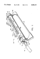
- FIG. 1 is a perspective view of an oscillating sprinkler utilizing the present invention
- FIG. 2 is a top view of the sprinkler shown in FIG. 1;
- FIG. 3A is a cross section, taken along line 3A of FIG. 2, of the proximal (water motor) end of the sprinkler;
- FIG. 3B is a cross section, taken along line 3B of FIG. 2, of the distal (rotary dial) end of the sprinkler;
- FIG. 4 is a distal end view of the sprinkler of FIG. 1;
- FIG. 5 is a cross section, taken along line 5 of FIG. 4, of the distal end of the sprinkler;
- FIG. 6A is a cross section, taken along line 6A of FIG. 2, showing a cam and plunger in "open” position;
- FIG. 6B is a cross section, taken along line 6B of FIG. 2, showing a cam and plunger in "closed” position;
- FIG. 7 is an isolated perspective view showing detail of the cooperation between the cam shaft and plungers and orifices of the water jets of the present invention.
- FIG. 8 is a plan view of the cam shaft and cam surfaces of the present invention.
- FIGS. 9-18 are cross sections of the cam shaft and cam surfaces of the present invention taken along the corresponding lines of FIG. 8;
- FIG. 19 is a geometric representation of the water jet status at differing rotational positions of the cam shaft of FIG. 8.
- an oscillating sprinkler 10 having an elongated generally tubular-shaped outer casing 12.
- Outer casing 12 is generally suspended between a pair of support members, proximal support member 15A and distal support member 15B, which are connected for stability by a pair of connecting members 22.
- Casing 12 is operably connectable at its proximal or water inlet end 14 to a housing 13 which is formed in the upper portion of a proximal support member 15A.
- the inlet end 14 of proximal support member 15A contains fittings to receive a fluid-carrying device 16, such as a garden hose.
- the distal end of the outer casing 12 of sprinkler 10 is operably connectable to distal support member 15B in the manner set forth in FIG. 3B and FIG. 5, a manner which is generally known.
- the interior of housing 13 of proximal support member 15A contains a water motor 26 (see, FIG. 3A) of the turbine variety which imparts the oscillating motion to casing 12, by a series of gears in connection with the water turbine (not shown) in a manner generally known.
- Housing 13 is also equipped with thumb operated adjusting knobs 17, which are employed to selectively vary the degree of oscillation, in a manner generally known.
- the degree of oscillation can be "marked” with markers 23 which fit into slots 21 in housing 13. In this way, once a desired oscillation pattern is achieved for a particular area, markers 23 can be inserted into the appropriate slots 21 so that the same oscillation pattern can be "dialed in” by adjusting thumb adjustments 17 to match the position of markers 23.
- Outer casing 12 receives a water tube 20 which is also suspended between support members 15A and 15B. Casing 12 does not carry any of the weight of water tube 20, and water tube 20 does not support any weight of casing 12.
- Water tube 20 is provided with a plurality of water jets 18 which emit water spray 19 therefrom to provide the desired irrigation.
- the 11 central water jets in area 18A remain in fluid contact all the time, so there is always spray 19 emitting therefrom when water supply is fed from hose 16 into inlet end 14 of housing.
- the five proximal end water jets in area 18B and the five distal water jets in area 18C are selectively operable in the manner hereinafter described, thereby permitting a selectively variable spray pattern.
- the water jets 18 of the present invention are arranged at different selected angles, to provide maximum area coverage of the spray 19 emitted from water jets 18.
- the upper region of distal support member 15B contains an upper portion in the form of a housing 24 to receive the distal end of cam shaft 30 (see. FIGS. 3B, 5 and 8).
- Cam shaft 30 is also operably connected to a cam adjustment dial 28 which is water-sealed separate from casing 12 (and water tube 20) and also freely rotatable independent of casing 12.
- Rotating cam adjustment dial 28 causes cam shaft 30 to be rotated on a 1:1 basis, causing water jets in area 18B and/or in area 18C to be selectively operable in the manner hereinafter described.
- Marker pieces 23 can be inserted into slots 29 of cam dial 28 after achieving a desired spray pattern, in a manner similar to that described above after a desired oscillating pattern is achieved.
- Housing 24 is provided with a removable end plug 32 which provides access to the interior thereof for cleaning purposes and the like.
- End plug 32 is connectable to cam shaft means 30 at their respective distal ends 36, 34, but such connection does not affect the operation of cam dial 28.
- Cam shaft 30 is maintained in proper alignment with cam dial 28 by a projecting fin or detent 31 thereon which fits into a corresponding slot 33 of cam dial 28 which in turn is received in concentric relationship by housing 24; this ensures that the operation of cam shaft 30 by cam dial 28 always begins from a known radial position, resulting in a predictable and programmed engagement or disengagement of water jets 18 (see, FIG. 19).
- Cam shaft 30 is provided with a plurality of cam surfaces 48 arranged in tripartite fashion (see FIG. 7) and a plurality of water interruption means in communication therewith.
- Each tripartite set of cam surfaces is aligned with a selected water jet 18 and is further provided with a corresponding water interruption means in the form of water interruption plunger or stopper assembly 50, each of which is aligned with a selected water jet 18.
- the plurality of water interruption plunger assemblies 50 are connected to and disposed around a central shaft 64 which extends above and parallel to the longitudinal axis of cam shaft 30.
- Shaft 64 is fixed at its ends to maintain the position of each water interruption plunger assembly 50 in relation to its corresponding cam surface 48.
- Each water interruption plunger or stopper assembly 50 is provided at its lower portion with two spaced apart cam-following legs 52 connected via struts 53 to a higher positioned center cam-following leg 54 disposed forward of and between the spaced-apart lower legs 52.
- the spaced apart cam-following legs 52 engage the outer cam surfaces 48A of tripartite cam surface 48, and central cam-following leg 54 engages the central cam surface 48B of cam surface.
- Spaced-apart legs 52 and central leg 54 are in turn connected to neck portion 56 which is provided with a flared stopper 58.
- Each flared stopper 58 is engageable with a corresponding orifice 60 formed in the upper region of water tube 20.
- Each orifice 60 is surrounded by a water tight gasket 62 (see also FIG. 3A) so that when flared stopper 58 of water interruption plunger assembly 50 is urged by the communication of legs 52 with cam surface 48A into engagement with orifice 60, a watertight seal is formed, thereby eliminating water flow into orifice 60 and out water jet 18.
- central leg 54 of water interruption plunger assembly 50 is in contact with the raised portion of center cam surface 48B and spaced-apart legs 52 are in contact with the non-raised portions of outer cam surfaces 48A, which causes water interruption plunger assembly 50 to rotate about rotation axis means 64 and pull flared stopper 58 away from contact with orifice 60, thereby permitting water 19 to flow therethrough and out water jet 18(1).
- FIG. 6A central leg 54 of water interruption plunger assembly 50 is in contact with the raised portion of center cam surface 48B and spaced-apart legs 52 are in contact with the non-raised portions of outer cam surfaces 48A, which causes water interruption plunger assembly 50 to rotate about rotation axis means 64 and pull flared stopper 58 away from contact with orifice 60, thereby permitting water 19 to flow therethrough and out water jet 18(1).
- central leg 54 of water interruption plunger assembly 50 is not in contact with the raised portion of center cam surface 48B while space-apart legs 52 are in contact with the raised portions of outer cam surfaces 48A, which causes water interruption plunger assembly 50 to rotate forward about rotation axis 64, thereby urging flared stopper 58 into contact with orifice 60 and gasket 62, fully interrupting water flow to the particular water jet 18(1).
- water interruption plunger assembly 50 may be programmed to be in contact with or not in contact with orifice 60.
- camshaft 30 may be rotated by cam dial 28 or end plug 32 to provide a selected variety of open or closed water jets 18 in areas 18B and/or 18C, and that this in turn determines the spray pattern of the water 19 emitted from water jets 18.
- an operator can "dial in” a selected spray pattern by rotating the cam shaft to achieve the desired open or closed status of water jets 18 in areas 18B and/or 18C.
- FIGS. 9--18 and 19 a particular arrangement of cam surfaces 48 on cam shaft 30 is shown which results in one particular set of selectable spray patterns.
- FIGS. 9--13 show the cam surface arrangement to control the status of water jets 18 in area 18B (shown in FIGS. 1 and 2 as water jets 18(1), 18(2), 18(3), 18(4) and 18(5)), and
- FIGS. 14--18 show the cam surface arrangement to control the status (open or closed) of water jets 18 in area 18C (shown in FIGS. 1 and 2 as water jets 18(6), 18(7), 18(8), 18(9) and 18(10)).
- the water jets 18 in area 18A are always open and operating.
- FIG. 9 is the cam surface relating to water jet 18(1), FIG. 10 to water jet 18(2), FIG. 11 to water jet 18(3), FIG. 12 to water jet 18(4) and FIG. 13 to water jet 18(5).
- FIG. 14 is the cam surface relating to water jet 18(6), FIG. 15 to water jet 18(7), FIG. 16 to water jet 18(8), FIG. 17 to water jet 18(9) and FIG. 18 to water jet 18(10).
- FIG. 19 shows how the different water jets 18 of water jet groupings 18B and 18C will be actuated by rotating cam dial 28.
- cam dial 28 When cam dial is aligned coincident with the fin or detent 31 of camshaft 30 (the "zero" position), all water jets 18 (1) through 18(10) are open or “on,” which is to say that each flared stepper 58 of each water interruption plunger assembly 50 is disengaged from each orifice 60, as shown in FIG. 6A.
- FIG. 19 shows how the different water jets are affected by this particular cam arrangement.
- Positions past the detent of zero position will be referred to as “position 1,” “position 2” on so on until “position 10,” the last position clockwise past the zero position.
- position 1 first position clockwise past the detent or “zero” position
- all water jets in area 18B are closed (water jets 18(1), 18(2), 18(3), 18(4) and 18(5) as shown in FIGS. 1 and 2), which is to say that flared stopper 58 of water interruption plunger assembly 50 has been urged into engagement with orifice 60 and surrounding gasket 62 of the affected water jets.
- position 2 water jets 18(1-5) of area 18B and water jet 18(10) of area 18C are closed.
- water jets are sequentially opened in pairs.
- water jets 18(5) and 18(6) are opened (the inner-most water jets of area 18B and 18C respectively).
- water jets 18(4) and 18(7) are opened in addition to water jets 18(5) and 18(6).
- water jets 18(3) and 18(8) are opened in addition to water jets 18(4), 18(5), 18(6) and 18(7).
- water jets 18(2) and 18(9) are additionally opened, leaving only the extreme outside water jet 18(1) of area 18B and water jet 18(10) of area 18C still off.
- water jets 18(1) and 18(10) are opened, resulting in the most full spray pattern achievable by this particular camshaft arrangement.
- the sprinkler 10 of the present invention may be manufactured using a variety of known materials, for example ABS thermoplastics such as polystyrene, polyethylene and the like, and using generally known techniques such as injection molding to make the individual components and sonic welding to join such components together.
- ABS thermoplastics such as polystyrene, polyethylene and the like
Abstract
Description
Claims (26)
Priority Applications (9)
| Application Number | Priority Date | Filing Date | Title |
|---|---|---|---|
| US08/101,651 US5350115A (en) | 1993-08-10 | 1993-08-10 | Lawn sprinkler with cam-controlled variable spray pattern |
| TW082106507A TW226971B (en) | 1993-08-10 | 1993-08-13 | Lawn sprinkler with cam-controlled variable spray pattern |
| CA002127509A CA2127509C (en) | 1993-08-10 | 1994-07-06 | Lawn sprinkler with cam-controlled variable spray pattern |
| AT94924617T ATE162430T1 (en) | 1993-08-10 | 1994-08-05 | LAWN IRRIGATION DEVICE WITH A VARIABLE SPRAY ARRANGEMENT CONTROLLED BY A SHAFT |
| ES94924617T ES2114214T3 (en) | 1993-08-10 | 1994-08-05 | LAWN SPRINKLER WITH CAM-CONTROLLED VARIABLE SPRAY. |
| DK94924617T DK0713426T3 (en) | 1993-08-10 | 1994-08-05 | Lawn with comb controlled variable spray pattern |
| EP94924617A EP0713426B1 (en) | 1993-08-10 | 1994-08-05 | Lawn sprinkler with cam controlled variable spray pattern |
| DE69408149T DE69408149T2 (en) | 1993-08-10 | 1994-08-05 | LAWN IRRIGATION DEVICE WITH A VARIABLE SPRAY ARRANGEMENT CONTROLLED BY A SHAFT |
| PCT/US1994/009021 WO1995004603A1 (en) | 1993-08-10 | 1994-08-05 | Lawn sprinkler with cam controlled variable spray pattern |
Applications Claiming Priority (1)
| Application Number | Priority Date | Filing Date | Title |
|---|---|---|---|
| US08/101,651 US5350115A (en) | 1993-08-10 | 1993-08-10 | Lawn sprinkler with cam-controlled variable spray pattern |
Publications (1)
| Publication Number | Publication Date |
|---|---|
| US5350115A true US5350115A (en) | 1994-09-27 |
Family
ID=22285737
Family Applications (1)
| Application Number | Title | Priority Date | Filing Date |
|---|---|---|---|
| US08/101,651 Expired - Lifetime US5350115A (en) | 1993-08-10 | 1993-08-10 | Lawn sprinkler with cam-controlled variable spray pattern |
Country Status (9)
| Country | Link |
|---|---|
| US (1) | US5350115A (en) |
| EP (1) | EP0713426B1 (en) |
| AT (1) | ATE162430T1 (en) |
| CA (1) | CA2127509C (en) |
| DE (1) | DE69408149T2 (en) |
| DK (1) | DK0713426T3 (en) |
| ES (1) | ES2114214T3 (en) |
| TW (1) | TW226971B (en) |
| WO (1) | WO1995004603A1 (en) |
Cited By (34)
| Publication number | Priority date | Publication date | Assignee | Title |
|---|---|---|---|---|
| WO1995032806A1 (en) * | 1994-06-01 | 1995-12-07 | L.R. Nelson Corporation | Unitized sprinkler assembly with adjustable water control mechanism |
| US5511727A (en) * | 1994-06-01 | 1996-04-30 | L. R. Nelson Corporation | Wave sprinkler with improved adjustable spray assembly |
| US5526982A (en) * | 1993-12-23 | 1996-06-18 | The Toro Company | Adjustable sprinkler nozzle |
| US5628458A (en) * | 1995-04-12 | 1997-05-13 | Kuo; Yu-Neng | Spray tube assembly for oscillating sprinklers |
| US5657928A (en) * | 1995-11-06 | 1997-08-19 | Jian; May-Be | Adjustment structure of a rotary sprinkler |
| USD383193S (en) * | 1995-05-26 | 1997-09-02 | L. R. Nelson Corporation | Wave sprinkler |
| US5735462A (en) * | 1995-01-03 | 1998-04-07 | Claber S.P.A. | Device for the transmission of motion to an oscillating arm of an irrigation device |
| AU713737B2 (en) * | 1994-06-01 | 1999-12-09 | L.R. Nelson Corporation | Unitized sprinkler assembly with adjustable water control mechanism |
| DE19830860A1 (en) * | 1998-07-10 | 2000-01-13 | Gardena Kress & Kastner Gmbh | Method for adjusting the sprinkler image of a sprinkler and sprinkler |
| EP0970752A3 (en) * | 1998-07-10 | 2000-01-19 | GARDENA Kress + Kastner GmbH | Method for adjusting the irrigation pattern of an sprinkling device and sprinkling device |
| US20020092931A1 (en) * | 1999-03-22 | 2002-07-18 | Coote Alex Marcos | Design of the nozzle arrangement on the spray tube of the conventional, oscillating lawn or hose sprinkler |
| US6736340B1 (en) * | 2003-05-28 | 2004-05-18 | Wang Tzu-Meng | Controlling device for a sprinkler |
| US20060102751A1 (en) * | 2004-11-12 | 2006-05-18 | L.R. Nelson Corporation | Oscillating sprinkler with pattern select feature |
| US20060192030A1 (en) * | 2005-02-02 | 2006-08-31 | Breedlove Michael G | Wind resistant oscillating sprinkler |
| US7258286B1 (en) * | 2006-03-24 | 2007-08-21 | Yuan Mei Corp. | Water shutoff and discharge control device for sprinklers |
| US20070221756A1 (en) * | 2006-03-27 | 2007-09-27 | Po-Hsiung Wang | Lawn sprinkler with changeable nozzles |
| US20070235568A1 (en) * | 2006-03-24 | 2007-10-11 | Yuan Mei Corp. | Water shutoff and discharge control apparatus for sprinklers |
| US20080054103A1 (en) * | 2006-08-31 | 2008-03-06 | Melnor, Inc. | Oscillating sprinkler with adjustable spray width |
| US20080116297A1 (en) * | 2006-11-21 | 2008-05-22 | Wang Tzu-Meng | Water sprinkling assembly |
| US20090090792A1 (en) * | 2005-05-23 | 2009-04-09 | Alan Amron | Device for discharging a stream of fluid in a pattern and method of using same |
| US20100038444A1 (en) * | 2008-08-15 | 2010-02-18 | Eldon Coppersmith | Oscillating Sprinkler that Automatically Produces a Rectangular Water Distribution Pattern |
| US20100078503A1 (en) * | 2008-09-30 | 2010-04-01 | Gilmour, Inc. | Water sprinkler with water motor |
| US20100078501A1 (en) * | 2008-09-30 | 2010-04-01 | Gilmour, Inc. | Water sprinkler with spray coverage adjustment mechanism |
| CN101015822B (en) * | 2006-02-10 | 2010-06-23 | 源美股份有限公司 | Water-entry automatic change-over device for water sprinkler |
| US20110101123A1 (en) * | 2009-11-03 | 2011-05-05 | Eldon Coppersmith | Oscillating sprinkler automatically producing evenly-spaced rectilinear watering and a rectangular watering pattern |
| US20110215168A1 (en) * | 2010-03-05 | 2011-09-08 | Gilmour, Inc. | Water Sprinkler |
| US20110226867A1 (en) * | 2010-03-18 | 2011-09-22 | Gilmour, Inc. | Water Sprinkler |
| US8087968B2 (en) | 2005-05-23 | 2012-01-03 | Thought Development, Inc. | Device for discharging a stream of fluid in a pattern and method of using same |
| US20140263732A1 (en) * | 2013-03-15 | 2014-09-18 | Robert Bosch Gmbh | Water Sprinkler |
| US20160345515A1 (en) * | 2009-12-17 | 2016-12-01 | Partners In Innovation Limited, Llc | Water management control device for watering devices |
| GB2563500A (en) * | 2018-05-29 | 2018-12-19 | Tonark Marketing Ltd | Water jet arrangement |
| US20190168244A1 (en) * | 2016-05-27 | 2019-06-06 | Ningbo Daye Garden Industry Co., Ltd | Oscillating sprinkler with adjustable spray area |
| US20200094284A1 (en) * | 2018-09-25 | 2020-03-26 | Ningbo Yilin Aguatech Co., Ltd. | Sprinkler with Locking Mechanism and Removable Nozzle Strip |
| US11173504B2 (en) * | 2019-10-21 | 2021-11-16 | Shin Tai Spurt Water Of The Garden Tools Co., Ltd. | Driving structure of a garden sprinkler |
Families Citing this family (1)
| Publication number | Priority date | Publication date | Assignee | Title |
|---|---|---|---|---|
| DE202011104874U1 (en) | 2011-08-27 | 2011-10-27 | Silag Handel Ag | Flat, rectangular or square sprinkler as irrigation device |
Citations (12)
| Publication number | Priority date | Publication date | Assignee | Title |
|---|---|---|---|---|
| US1517664A (en) * | 1923-03-19 | 1924-12-02 | Nels J Veline | Extension lawn sprinkler |
| US2869630A (en) * | 1954-04-28 | 1959-01-20 | John H Flynn | Gas burner with selective flame distribution |
| US3332624A (en) * | 1965-01-28 | 1967-07-25 | First Res Corp | Turret lawn sprinkler with oscillating mechanism |
| US3423024A (en) * | 1966-11-03 | 1969-01-21 | Sunbeam Corp | Flow restrictor for lawn sprinkler |
| US3647140A (en) * | 1969-05-24 | 1972-03-07 | Perrot Regnerbau Gmbh & Co | Sprinkler construction |
| DE3119094A1 (en) * | 1981-05-14 | 1982-11-25 | Perrot-Regnerbau Gmbh & Co, 7260 Calw | Sprinkler adjustable to different sprinkling areas and water pressures |
| US4417691A (en) * | 1976-11-08 | 1983-11-29 | Anthony Manufacturing Corp. | Turbine drive water sprinkler |
| US4568023A (en) * | 1983-06-30 | 1986-02-04 | L. R. Nelson Corporation | Uniform motion oscillatory wave sprinkler |
| US4721248A (en) * | 1986-04-14 | 1988-01-26 | Jet Stream, Inc. | Readily assembleable oscillating sprinkler |
| US5042719A (en) * | 1989-04-26 | 1991-08-27 | Uniflex Utiltime S.P.A. | Oscillating lawn sprinkler |
| US5052622A (en) * | 1988-10-06 | 1991-10-01 | Gardena Kress & Kastner Gmbh | Sprinkler |
| US5052621A (en) * | 1988-10-06 | 1991-10-01 | Gardena Kress & Kastner Gmbh | Drive mechanism for a sprinkler or the like |
Family Cites Families (1)
| Publication number | Priority date | Publication date | Assignee | Title |
|---|---|---|---|---|
| US4860954A (en) * | 1987-04-20 | 1989-08-29 | Rain Bird Consumer Products Mfg. Corp. | Adjustable oscillating wave-type sprinkler |
-
1993
- 1993-08-10 US US08/101,651 patent/US5350115A/en not_active Expired - Lifetime
- 1993-08-13 TW TW082106507A patent/TW226971B/en active
-
1994
- 1994-07-06 CA CA002127509A patent/CA2127509C/en not_active Expired - Fee Related
- 1994-08-05 AT AT94924617T patent/ATE162430T1/en not_active IP Right Cessation
- 1994-08-05 DK DK94924617T patent/DK0713426T3/en active
- 1994-08-05 ES ES94924617T patent/ES2114214T3/en not_active Expired - Lifetime
- 1994-08-05 WO PCT/US1994/009021 patent/WO1995004603A1/en active IP Right Grant
- 1994-08-05 DE DE69408149T patent/DE69408149T2/en not_active Expired - Fee Related
- 1994-08-05 EP EP94924617A patent/EP0713426B1/en not_active Expired - Lifetime
Patent Citations (12)
| Publication number | Priority date | Publication date | Assignee | Title |
|---|---|---|---|---|
| US1517664A (en) * | 1923-03-19 | 1924-12-02 | Nels J Veline | Extension lawn sprinkler |
| US2869630A (en) * | 1954-04-28 | 1959-01-20 | John H Flynn | Gas burner with selective flame distribution |
| US3332624A (en) * | 1965-01-28 | 1967-07-25 | First Res Corp | Turret lawn sprinkler with oscillating mechanism |
| US3423024A (en) * | 1966-11-03 | 1969-01-21 | Sunbeam Corp | Flow restrictor for lawn sprinkler |
| US3647140A (en) * | 1969-05-24 | 1972-03-07 | Perrot Regnerbau Gmbh & Co | Sprinkler construction |
| US4417691A (en) * | 1976-11-08 | 1983-11-29 | Anthony Manufacturing Corp. | Turbine drive water sprinkler |
| DE3119094A1 (en) * | 1981-05-14 | 1982-11-25 | Perrot-Regnerbau Gmbh & Co, 7260 Calw | Sprinkler adjustable to different sprinkling areas and water pressures |
| US4568023A (en) * | 1983-06-30 | 1986-02-04 | L. R. Nelson Corporation | Uniform motion oscillatory wave sprinkler |
| US4721248A (en) * | 1986-04-14 | 1988-01-26 | Jet Stream, Inc. | Readily assembleable oscillating sprinkler |
| US5052622A (en) * | 1988-10-06 | 1991-10-01 | Gardena Kress & Kastner Gmbh | Sprinkler |
| US5052621A (en) * | 1988-10-06 | 1991-10-01 | Gardena Kress & Kastner Gmbh | Drive mechanism for a sprinkler or the like |
| US5042719A (en) * | 1989-04-26 | 1991-08-27 | Uniflex Utiltime S.P.A. | Oscillating lawn sprinkler |
Cited By (52)
| Publication number | Priority date | Publication date | Assignee | Title |
|---|---|---|---|---|
| US5526982A (en) * | 1993-12-23 | 1996-06-18 | The Toro Company | Adjustable sprinkler nozzle |
| WO1995032806A1 (en) * | 1994-06-01 | 1995-12-07 | L.R. Nelson Corporation | Unitized sprinkler assembly with adjustable water control mechanism |
| US5511727A (en) * | 1994-06-01 | 1996-04-30 | L. R. Nelson Corporation | Wave sprinkler with improved adjustable spray assembly |
| US5645218A (en) * | 1994-06-01 | 1997-07-08 | L. R. Nelson Corporation | Unitized sprinkler assembly with adjustable water control mechanism |
| AU695908B2 (en) * | 1994-06-01 | 1998-08-27 | L.R. Nelson Corporation | Unitized sprinkler assembly with adjustable water control mechanism |
| US5938122A (en) * | 1994-06-01 | 1999-08-17 | L.R. Nelson Corporation | System and process for producing sprinkler assemblies |
| AU713737B2 (en) * | 1994-06-01 | 1999-12-09 | L.R. Nelson Corporation | Unitized sprinkler assembly with adjustable water control mechanism |
| US5735462A (en) * | 1995-01-03 | 1998-04-07 | Claber S.P.A. | Device for the transmission of motion to an oscillating arm of an irrigation device |
| US5628458A (en) * | 1995-04-12 | 1997-05-13 | Kuo; Yu-Neng | Spray tube assembly for oscillating sprinklers |
| USD383193S (en) * | 1995-05-26 | 1997-09-02 | L. R. Nelson Corporation | Wave sprinkler |
| US5657928A (en) * | 1995-11-06 | 1997-08-19 | Jian; May-Be | Adjustment structure of a rotary sprinkler |
| US6135356A (en) * | 1998-07-10 | 2000-10-24 | Gardena Kress + Kastner Gmbh | Method for adjusting the sprinkling pattern of a sprinkling apparatus and sprinkling apparatus |
| DE19830860A1 (en) * | 1998-07-10 | 2000-01-13 | Gardena Kress & Kastner Gmbh | Method for adjusting the sprinkler image of a sprinkler and sprinkler |
| US6062490A (en) * | 1998-07-10 | 2000-05-16 | Gardena Kress +Kastner Gmbh | Method for adjusting the sprinkling pattern of a sprinkling apparatus and sprinkling apparatus |
| EP0970752A3 (en) * | 1998-07-10 | 2000-01-19 | GARDENA Kress + Kastner GmbH | Method for adjusting the irrigation pattern of an sprinkling device and sprinkling device |
| US20020092931A1 (en) * | 1999-03-22 | 2002-07-18 | Coote Alex Marcos | Design of the nozzle arrangement on the spray tube of the conventional, oscillating lawn or hose sprinkler |
| US6736340B1 (en) * | 2003-05-28 | 2004-05-18 | Wang Tzu-Meng | Controlling device for a sprinkler |
| US20060102751A1 (en) * | 2004-11-12 | 2006-05-18 | L.R. Nelson Corporation | Oscillating sprinkler with pattern select feature |
| US7252246B2 (en) | 2004-11-12 | 2007-08-07 | L.R. Nelson Corporation | Oscillating sprinkler with pattern select feature |
| US20060192030A1 (en) * | 2005-02-02 | 2006-08-31 | Breedlove Michael G | Wind resistant oscillating sprinkler |
| US7624934B2 (en) | 2005-02-02 | 2009-12-01 | Robert Bosch Tool Corporation | Wind resistant oscillating sprinkler |
| US20090090792A1 (en) * | 2005-05-23 | 2009-04-09 | Alan Amron | Device for discharging a stream of fluid in a pattern and method of using same |
| US8087968B2 (en) | 2005-05-23 | 2012-01-03 | Thought Development, Inc. | Device for discharging a stream of fluid in a pattern and method of using same |
| CN101015822B (en) * | 2006-02-10 | 2010-06-23 | 源美股份有限公司 | Water-entry automatic change-over device for water sprinkler |
| US7258286B1 (en) * | 2006-03-24 | 2007-08-21 | Yuan Mei Corp. | Water shutoff and discharge control device for sprinklers |
| US7284714B1 (en) * | 2006-03-24 | 2007-10-23 | Yuan Mei Corp. | Water shutoff and discharge control apparatus for sprinklers |
| US20070235568A1 (en) * | 2006-03-24 | 2007-10-11 | Yuan Mei Corp. | Water shutoff and discharge control apparatus for sprinklers |
| US20070221756A1 (en) * | 2006-03-27 | 2007-09-27 | Po-Hsiung Wang | Lawn sprinkler with changeable nozzles |
| US20080054103A1 (en) * | 2006-08-31 | 2008-03-06 | Melnor, Inc. | Oscillating sprinkler with adjustable spray width |
| US7607590B2 (en) * | 2006-08-31 | 2009-10-27 | Melnor, Inc. | Oscillating sprinkler with adjustable spray width |
| US20080116297A1 (en) * | 2006-11-21 | 2008-05-22 | Wang Tzu-Meng | Water sprinkling assembly |
| US7448558B2 (en) * | 2006-11-21 | 2008-11-11 | Wang Tzu-Meng | Water sprinkling assembly |
| US20100038444A1 (en) * | 2008-08-15 | 2010-02-18 | Eldon Coppersmith | Oscillating Sprinkler that Automatically Produces a Rectangular Water Distribution Pattern |
| US8011602B2 (en) * | 2008-08-15 | 2011-09-06 | Eldon Coppersmith | Oscillating sprinkler that automatically produces a rectangular water distribution pattern |
| US20100078501A1 (en) * | 2008-09-30 | 2010-04-01 | Gilmour, Inc. | Water sprinkler with spray coverage adjustment mechanism |
| US7988072B2 (en) | 2008-09-30 | 2011-08-02 | Robert Bosch Gmbh | Water sprinkler with water motor |
| US7988067B2 (en) | 2008-09-30 | 2011-08-02 | Robert Bosch Gmbh | Water sprinkler with spray coverage adjustment mechanism |
| US20100078503A1 (en) * | 2008-09-30 | 2010-04-01 | Gilmour, Inc. | Water sprinkler with water motor |
| US20110101123A1 (en) * | 2009-11-03 | 2011-05-05 | Eldon Coppersmith | Oscillating sprinkler automatically producing evenly-spaced rectilinear watering and a rectangular watering pattern |
| US8567692B2 (en) | 2009-11-03 | 2013-10-29 | Eldon Coppersmith | Oscillating sprinkler automatically producing evenly-spaced rectilinear watering and a rectangular watering pattern |
| US20160345515A1 (en) * | 2009-12-17 | 2016-12-01 | Partners In Innovation Limited, Llc | Water management control device for watering devices |
| US8695902B2 (en) * | 2010-03-05 | 2014-04-15 | Robert Bosch Gmbh | Water sprinkler |
| US20110215168A1 (en) * | 2010-03-05 | 2011-09-08 | Gilmour, Inc. | Water Sprinkler |
| US8505836B2 (en) | 2010-03-18 | 2013-08-13 | Robert Bosch Gmbh | Water sprinkler |
| US20110226867A1 (en) * | 2010-03-18 | 2011-09-22 | Gilmour, Inc. | Water Sprinkler |
| US20140263732A1 (en) * | 2013-03-15 | 2014-09-18 | Robert Bosch Gmbh | Water Sprinkler |
| US9669420B2 (en) * | 2013-03-15 | 2017-06-06 | Fiskars Oyj Abp | Water sprinkler |
| US20190168244A1 (en) * | 2016-05-27 | 2019-06-06 | Ningbo Daye Garden Industry Co., Ltd | Oscillating sprinkler with adjustable spray area |
| GB2563500A (en) * | 2018-05-29 | 2018-12-19 | Tonark Marketing Ltd | Water jet arrangement |
| US20200094284A1 (en) * | 2018-09-25 | 2020-03-26 | Ningbo Yilin Aguatech Co., Ltd. | Sprinkler with Locking Mechanism and Removable Nozzle Strip |
| US11161137B2 (en) * | 2018-09-25 | 2021-11-02 | Ningbo Yilin Aquatech Co., Ltd. | Sprinkler with locking mechanism and removable nozzle strip |
| US11173504B2 (en) * | 2019-10-21 | 2021-11-16 | Shin Tai Spurt Water Of The Garden Tools Co., Ltd. | Driving structure of a garden sprinkler |
Also Published As
| Publication number | Publication date |
|---|---|
| WO1995004603A1 (en) | 1995-02-16 |
| CA2127509C (en) | 2003-01-28 |
| EP0713426A1 (en) | 1996-05-29 |
| DE69408149T2 (en) | 1998-05-07 |
| EP0713426B1 (en) | 1998-01-21 |
| CA2127509A1 (en) | 1995-02-11 |
| DE69408149D1 (en) | 1998-02-26 |
| TW226971B (en) | 1994-07-21 |
| ES2114214T3 (en) | 1998-05-16 |
| DK0713426T3 (en) | 1998-09-21 |
| ATE162430T1 (en) | 1998-02-15 |
Similar Documents
| Publication | Publication Date | Title |
|---|---|---|
| US5350115A (en) | Lawn sprinkler with cam-controlled variable spray pattern | |
| US6241158B1 (en) | Irrigation sprinkler with pivoting throttle valve | |
| USRE29405E (en) | Spray apparatus | |
| US4177947A (en) | Irrigation device | |
| US4836450A (en) | Sprinkler unit with alternating stream interruptor | |
| US5299743A (en) | Body spray nozzle | |
| US5098020A (en) | Adjustable oscillating wave-type sprinkler | |
| US4119275A (en) | Fluid spray head and method adapted to spray specific pattern | |
| US4588130A (en) | Showerhead | |
| US5009368A (en) | Constant-pressure, variable-volume irrigation sprinklers | |
| US4357779A (en) | Hand held liquid herbicide applicator | |
| US3423024A (en) | Flow restrictor for lawn sprinkler | |
| US5307993A (en) | Rotary sprinkler | |
| EP0394653B1 (en) | Oscillating lawn sprinklers | |
| EP0826427A2 (en) | Oscillating sprinklers | |
| US3319893A (en) | Sprinkler | |
| US3762650A (en) | Adjustable spray head | |
| US3767118A (en) | Oscillating water sprinkler | |
| EP0648544B1 (en) | Irrigator with an oscillating arm | |
| US4033509A (en) | Lawn sprinkler and fertilizer dispenser | |
| US3790082A (en) | Sprinkler | |
| WO2004064498A1 (en) | Sprinkler system | |
| US20050127203A1 (en) | Transverse axes oscillating water sprinkler with cam driven, oscillating nozzles | |
| US5630551A (en) | In-ground reciprocating sprinkler | |
| US3680783A (en) | Fluid spreading apparatus |
Legal Events
| Date | Code | Title | Description |
|---|---|---|---|
| AS | Assignment |
Owner name: VERMONT AMERICAN CORPORATION, KENTUCKY Free format text: ASSIGNMENT OF ASSIGNORS INTEREST;ASSIGNOR:BURNWORTH, DOUGLAS J.;REEL/FRAME:006651/0376 Effective date: 19930809 |
|
| AS | Assignment |
Owner name: VERMONT AMERICAN CORPORATION, KENTUCKY Free format text: ASSIGNMENT OF ASSIGNORS INTEREST;ASSIGNOR:LUNGERSHAUSEN, JOACHIM H.;REEL/FRAME:006858/0971 Effective date: 19940121 |
|
| STCF | Information on status: patent grant |
Free format text: PATENTED CASE |
|
| AS | Assignment |
Owner name: GILMOUR, INC., DELAWARE Free format text: ASSIGNMENT OF ASSIGNORS INTEREST;ASSIGNOR:GILMOUR MANUFACTURING COMPANY;REEL/FRAME:007757/0500 Effective date: 19950228 |
|
| FEPP | Fee payment procedure |
Free format text: PAYOR NUMBER ASSIGNED (ORIGINAL EVENT CODE: ASPN); ENTITY STATUS OF PATENT OWNER: LARGE ENTITY |
|
| FPAY | Fee payment |
Year of fee payment: 4 |
|
| FPAY | Fee payment |
Year of fee payment: 8 |
|
| FEPP | Fee payment procedure |
Free format text: PAYER NUMBER DE-ASSIGNED (ORIGINAL EVENT CODE: RMPN); ENTITY STATUS OF PATENT OWNER: LARGE ENTITY Free format text: PAYOR NUMBER ASSIGNED (ORIGINAL EVENT CODE: ASPN); ENTITY STATUS OF PATENT OWNER: LARGE ENTITY |
|
| FPAY | Fee payment |
Year of fee payment: 12 |