US5361385A - Parallel computing system for volumetric modeling, data processing and visualization - Google Patents
Parallel computing system for volumetric modeling, data processing and visualization Download PDFInfo
- Publication number
- US5361385A US5361385A US07/936,178 US93617892A US5361385A US 5361385 A US5361385 A US 5361385A US 93617892 A US93617892 A US 93617892A US 5361385 A US5361385 A US 5361385A
- Authority
- US
- United States
- Prior art keywords
- local
- computing unit
- memory storage
- parallel
- voxel
- Prior art date
- Legal status (The legal status is an assumption and is not a legal conclusion. Google has not performed a legal analysis and makes no representation as to the accuracy of the status listed.)
- Expired - Lifetime
Links
Images


Classifications
-
- G—PHYSICS
- G06—COMPUTING; CALCULATING OR COUNTING
- G06T—IMAGE DATA PROCESSING OR GENERATION, IN GENERAL
- G06T1/00—General purpose image data processing
- G06T1/20—Processor architectures; Processor configuration, e.g. pipelining
-
- G—PHYSICS
- G06—COMPUTING; CALCULATING OR COUNTING
- G06F—ELECTRIC DIGITAL DATA PROCESSING
- G06F15/00—Digital computers in general; Data processing equipment in general
- G06F15/76—Architectures of general purpose stored program computers
- G06F15/80—Architectures of general purpose stored program computers comprising an array of processing units with common control, e.g. single instruction multiple data processors
- G06F15/8007—Architectures of general purpose stored program computers comprising an array of processing units with common control, e.g. single instruction multiple data processors single instruction multiple data [SIMD] multiprocessors
- G06F15/8015—One dimensional arrays, e.g. rings, linear arrays, buses
-
- G—PHYSICS
- G06—COMPUTING; CALCULATING OR COUNTING
- G06T—IMAGE DATA PROCESSING OR GENERATION, IN GENERAL
- G06T15/00—3D [Three Dimensional] image rendering
- G06T15/005—General purpose rendering architectures
Definitions
- the present invention relates to an advanced method and apparatus for parallel computing which is versatile and suitable for use in computationally demanding applications, including real-time visualization of volumetric data.
- serial computing machines One major drawback of serial computing machines is that while the central processor is kept active, most of the memory is idle during processing operations. Another major drawback is that serial computing machines are inherently slow, since during each phase of a computation, many of the components of the processor are idle.
- VLIW very long word
- problems include, for example, simulation of atomic or particle interaction in the fields of computational physics and chemistry; simulation of gravitational interplay among celestial objects in the field of computational cosmology; simulation of biological cell processes in the field of computational biology; climate modeling and forecasting in the field of computational meteorology; air-traffic control; flight simulation; and knowledge-base searching in artificial intelligence (AI) systems.
- AI artificial intelligence
- serial computing machines One solution to the problem posed by serial computing machines has been to use a parallel processing design in which many small processors are linked together to work simultaneously so that both memory capacity and processing capacity can be utilized with high efficiency.
- a number of parallel computing machines have been constructed. In general, the character and performance of such computing machines are determined by three factors: (i) the nature, size and number of the processing elements; (ii) the nature, size and number of the memory nodes; and (iii) the strategy of interconnecting the processors and the memories.
- SIMD Single-Instruction-Stream-Multiple-Data-Stream
- a SIMD computing machine has a single control unit that broadcasts one instruction at a time to all of the processors which execute the instructions on multiple data sets simultaneously.
- commercially available SIMD computing machines can be grouped into two distinct classes.
- the first class of SIMD computing machine includes numeric supercomputers and other parallel computing machines that operate on vectors by performing the same operation on each vector element.
- each processor in this class of SIMD computing machinery is a vector processor consisting of an array of arithmetic logic units (ALU's) particularly adapted for processing vector formatted data.
- ALU's arithmetic logic units
- Each vector processor is provided access to a common memory, and there is no interprocessor connections or other provision for the parallel vector processors to share information among themselves.
- this class of SIMD machine receives two n-element vectors b[i] and c[i] as input, and operates on corresponding elements in parallel using the vector ALU's to provide an n-element vector a[i] as output.
- the Cray-1 Supercomputer from the Cray Computer Corporation is representative of this first class of SIMD computing machine.
- the second class of SIMD computing machine includes parallel-type computing machines which facilitate coordinated communication among the parallel processors.
- each processor in this second class of SIMD computing machines is a simple ALU which is provided access to a local memory which it controls.
- Each ALU can communicate with other ALU's through a communication network having either a fixed or programmable topology.
- 65,536 1-bit ALU's are configured as parallel processors and an interprocessor communication network having the topology of a n-cube or hypercube is provided for the transfer of data among these parallel processors.
- a single control unit broadcasts instructions to the 65,536 independent ALU processors.
- the ALU processors are individually small and slow, the total computation and input/output throughput of the Connection Machine computer is quite substantial because of the assembled power of its processing units and interprocessor communication system.
- the instructions of the program must be downloaded while the program is running. Consequently, a high bandwidth is required between the host system and the Connection Machine computer, resulting in relatively long cycle times.
- connection Machine and Cray-1 parallel computer systems each perform well in a number of advanced parallel computing applications, they both are poorly suited for volume visualization applications. Consequently, a variety of special purpose computing machines exploiting parallelism have been built in order to perform volume visualization tasks quickly.
- a number of prior art 3-D graphics-display and voxel-based computer graphic systems are described in detail in Applicant's U.S. Pat. No. 4,985,856 which is incorporated herein by reference.
- a further object of the present invention is to provide such a method and apparatus in which each local computing unit executes a local routine in its program memory, in a manner coordinated by the control computing unit simultaneously executing a control routine in its program memory, in response to a user interface/display routine running on an operably associated user interface and display computing unit.
- a further object of the present invention is to provide such apparatus in the form of a reconfigurable parallel computing machine having memory storage elements indexed so as to represent a three-dimensional array of N 3 memory storage elements arranged in 3-D Cartesian Space having three orthographic coordinate axes, and in which the control computing unit selectively coordinates the plurality of local computing units to access in parallel a Cartesian specified sequence of memory storage elements within the three-dimensional array, such that each memory storage element is always accessed by a different local computing unit for conflict-free memory storage access.
- a further object of the present invention is to provide such a parallel computing machine, in which the control computing unit coordinates the local computing units to access in parallel, a rectilinear sequence of N memory storage elements parallel to any one of the orthographic coordinate axes, such that each memory storage element is accessed by a different local computing unit for conflict-free memory storage access.
- a further object of the present invention is to provide such a parallel computing system, in which the control computing unit coordinates the local computing units to access in parallel a sequence of N memory storage elements residing within a Cartesian specified plane parallel to any one of the principal planes in 3-D Cartesian space, such that each memory storage element is accessed by a different local computing unit for conflict-free memory storage access.
- a further object of the present invention is to provide such a parallel computing machine, in which the control computing unit coordinates the local computing unit to access in parallel, a sequence of N memory storage elements extending through the 3-D memory storage array, such that each memory storage element is accessed by a different local computing unit for conflict-free memory storage access.
- a further object of the present invention is to provide such a parallel computing machine, in which an external parallel data input/output unit is provided for loading and unloading of sequences of data elements under the control of the control computing unit.
- An even further object of the present invention is to provide such a parallel computing machine with a global data transfer network, in which the control computing unit receives user provided Cartesian parameters which, in turn, are provided to the local computing units to create in a parallel fashion, a voxel based image of a specified 3-D geometric object which is then stored within the 3-D memory storage array.
- Yet an even further object of the present invention is to provide such a parallel computing machine, in which various physical or virtual processes can be simulated and viewed from any arbitrary viewing direction in 3-D Cartesian Space.
- geometric objects are specified in the user interface/display computing unit using conventional 3-D geometric specifications, are subsequently converted into implicit representations, and are then provided to the control computing unit.
- implicit representations are used to create, in a parallel fashion, within the 3-D memory storage array, voxel based images of the specified geometric objects.
- An even further object of the present invention is to provide such a parallel computing machine, in which a global data transfer network is provided so that each data element on the k-th local data bus is simultaneously transferred to the (k+ k)th node data bus, where k represents the module distance that each data element is transferred during a global data transfer cycle.
- An even further object of the present invention is to provide such a parallel computing machine with a local data transfer network, in which each k-th local computing unit can transfer data elements to the (k ⁇ 1)th, (k ⁇ 2) or (k ⁇ 3)th local computing units under the control of its own local routine.
- Yet an even further object of the present invention is to provide such a parallel computing machine which can coordinate the operation of the local computing units in the local data transfer network so as to achieve high speed data communication between any pair of local computing units.
- a further object of the present invention is to provide a method for reconfiguring a parallel computing machine having memory storage elements indexed so as to represent a 3-D memory storage array of N 3 memory storage elements arranged in 3-D Cartesian Space characterized by three orthographic coordinate axes, and in which the control computing unit selectively coordinates the plurality of local computing units to access in parallel a Cartesian specified sequence of memory storage elements within the 3-D memory storage array, such that each memory storage element is always accessed by a different local computing unit for conflict-free memory storage access.
- a further object of the present invention is to provide a method of accessing, in parallel, a rectilinear sequence of N memory storage elements residing along a beam parallel to any one of the orthographic coordinate axes, such that each memory storage element is accessed by a different local computing unit for conflict-free memory storage access.
- a further object of the present invention is to provide a method of accessing, in parallel, a sequence of N memory storage elements residing within a Cartesian specified plane parallel to any one of the principal planes in 3-D Cartesian Space, such that each memory storage element is accessed by a different local computing unit for conflict-free memory storage access.
- a further object of the present invention is to provide a method of accessing, in parallel, a sequence of N memory storage elements extending through the 3-D memory storage array, such that each memory storage element is accessed by a different local computing unit for conflict-free memory storage access.
- a further object of the present invention is to provide a method for loading into and unloading from a parallel computing machine, sequences of data elements.
- Yet an even further object of the present invention is to provide a method of simulating within a parallel computing machine, various physical or virtual processes which can be viewed, in real-time, from any arbitrary viewing direction in 3-D Cartesian Space.
- the method involves specifying the 3-D geometric objects in the user interface/display computing unit using conventional 3-D geometric specifications, subsequently converting the geometric specifications into implicit representations, and then providing these implicit representations to a control computing unit which broadcasts these inplicit representations to an array of local computing units in order to create, within the 3-D memory storage array, in a parallel fashion, voxel-based images of the specified geometric objects.
- FIG. 1A is high-level block diagram of the first embodiment of the parallel computing system of the present invention, shown interfaced with a user interface and display computing unit and an external data storage system;
- FIG. 1B is a high-level block diagram of the second embodiment of the parallel computing system of the present invention, shown interfaced with an external data storage system;
- FIG. 2 is a schematic diagram of the parallel computing system of an exemplary embodiment of the present invention, showing a 3-D matrix model of a 4 ⁇ 4 ⁇ 4 storage memory array operably associated with an array of four local computing units, a control computing unit, the parallel data input/output unit, local and global data transfer circuitry, and a data collection unit;
- FIG. 3 is a schematic diagram illustrating how the transfer of a data element from memory storage element m 1 (x 1 ,y 1 ,z 1 ) to memory storage element m 2 (x 2 ,y 2 ,z 2 ) in the 3-D Cartesian Space of the parallel computing system corresponds to the transfer of the data element from memory storage element m 1 (i 1 ,j 1 ,k 1 ) to memory storage element m 2 (i 2 ,j 2 ,k 2 ) in the Physical Memory Storage Space M 3 of the parallel computing system of the present invention;
- FIG. 4 is a schematic diagram of the parallel computing system of the illustrative embodiment of the present invention, showing the user interface and display computing unit, the control computing unit, the system bus, the control and synchronizing bus, the local data buses, the parallel data input/output unit, the data collection unit and N modules each including a local computing unit, a local memory storage module and a local bus interface controller;
- FIG. 4A is a schematic diagram of the data collection unit of the parallel computing system of FIG. 4;
- FIG. 4B is a schematic diagram of the data input/output unit of the parallel computing system of FIG. 4;
- FIG. 4C is a schematic diagram of the global and local data transfer networks of the parallel computing system of FIG. 4;
- FIG. 4D(1) is a schematic diagram illustrating the components comprising the local data communication data network of the Illustrative Embodiment which is capable of achieving data transfer among 26-connected neighboring memory storage elements of the parallel computing system of the present invention
- FIG. 4D(2) is a schematic diagram illustrating the interface between an adjacent pair of local buses and local computing units associated thereto, by way of the local bus interface controllers;
- FIG. 4E(1) is a schematic diagram of the global data transfer subunit used for transferring each bit of a data element within the global data transfer mechanism of the present invention
- FIG. 4E(2) is a schematic diagram of the global data transfer mechanism employed in the parallel computing system of the Illustrative Embodiment the present invention.
- FIG. 4E(3) is a schematic diagram of the switching element utilized within each global data transfer subunit shown in FIG. 4E(2);
- FIG. 5A is a flow chart for the user interface computer routine executed by the user interface and display computing unit in order to direct the control computing unit to coordinate the array of local computing units to effectuate a uniform intermodule transfer of the rectilinear sequence of data elements between source and destination sequences of memory storage elements specified by the Cartesian parameters illustrated in FIG. 5;
- FIG. 5B is a flow chart for a control computer routine executed by the control computing unit in order to coordinate the array of local computing units to effectuate a global data transfer of the rectilinear sequence of data elements between source and destination sequences of memory storage elements, as illustrated in FIG. 5;
- FIG. 5C is a flow chart for a local computer routine executed by each local computing unit during the uniform intermodule transfer of the rectilinear sequence of data elements between source and destination memory storage elements, as illustrated in FIG. 5;
- FIG. 6A through 6C are flow charts of computer routines executed by the user interface and display computing unit, the control computing unit and the local computing units, respectively, during the various parallel data access operations illustrated in FIGS. 6D through 6J;
- FIG. 6D is a schematic representation of the 4 ⁇ 4 ⁇ 4 memory storage array of FIG. 2, illustrating the access of a rectilinear sequence of four memory storage elements parallel to the z axis in 3-D Cartesian space C 3 and the location of these accessed memory storage elements in Physical Memory Storage Space M 3 ;
- FIG. 6E is a schematic representation of the 4 ⁇ 4 ⁇ 4 memory storage array of FIG. 2, illustrating the access of a rectilinear sequence of four memory storage elements parallel to the y axis in 3-D Cartesian Space C 3 and the location of these accessed memory storage elements in Physical Memory Storage Space M 3 ;
- FIG. 6F is a schematic representation of the 4 ⁇ 4 ⁇ 4 memory storage array of FIG. 2, illustrating the access of a rectilinear sequence of four memory storage elements parallel to the x axis in 3-D Cartesian Space C 3 and the location of these accessed memory storage elements in Physical Memory Storage Space M 3 ;
- FIG. 6G is a schematic representation of the 4 ⁇ 4 ⁇ 4 memory storage array of FIG. 2, illustrating the access of four memory storage elements residing within a plane parallel to the x-y place of 3-D Cartesian Space C 3 and the location of these accessed memory storage elements in Physical Memory Storage Space M 3 ;
- FIG. 6H is a schematic representation of the 4 ⁇ 4 ⁇ 4 memory storage array of FIG. 2, illustrating the access of four memory storage elements residing within a plane parallel to the x-z plane of 3-D Cartesian Space C 3 and the location of these accessed memory storage elements in Physical Memory Storage Space M 3 ;
- FIG. 6I is a schematic representation of the 4 ⁇ 4 ⁇ 4 memory storage array of FIG. 2, illustrating the access of memory storage elements residing within a plane parallel to the y-z plane of 3-D Cartesian Space C3 and the location of these accessed memory storage elements in Physical Memory Storage Space M 3 ;
- FIG. 6J is a schematic representation of the 4 ⁇ 4 ⁇ 4 memory storage array of FIG. 2, illustrating the access of four memory storage elements residing within the array in 3-D Cartesian Space C 3 and the location of these accessed memory storage elements in Physical Memory Storage Space M 3 ;
- FIG. 7A is a schematic representation illustrating, in both 3-D Cartesian Space C 3 and physical memory space M 3 , the location of a group of neighboring memory storage elements arranged in a 6-connected manner about a central memory storage element located at coordinates x,y,z in the 3-D memory storage array of the parallel computing system of the present invention
- FIG. 7B is a schematic representation illustrating, in both 3-D Cartesian Space C 3 and Physical Memory Storage Space M 3 , the location of a group of neighboring memory storage elements arranged in a 18-connected manner about a memory storage element located at coordinates x,y,z in the 3-D memory storage array of the parallel computing system of the present invention;
- FIG. 7C is a schematic representation illustrating, in both 3-D Cartesian Space C 3 and Physical Memory Storage Space M 3 , the location of a group of neighboring memory storage elements arranged in a 26-connected manner about a memory storage element located at coordinates x,y,z in the 3-D memory storage array of the parallel computing system of the present invention;
- FIG. 8 is a schematic representation of the 3-D memory storage array of the parallel computing system in Cartesian Space C 3 , in which 6-connected neighboring memory storage elements about the central memory storage elements lying along a Cartesian specified rectilinear sequence RS0, are accessed and data elements therein transferred to each such central memory storage element using the global data transfer network of the parallel computing system of the present invention;
- FIG. 8A is a flow chart of the control computer routine executed by the control computing unit in order to coordinate the local computing units and control the global data transfer mechanism so as to achieve global data transfer among 6-connected neighboring memory storage elements, as illustrated in FIG. 8;
- FIG. 8B is a flow chart of the global data transfer routine of FIG. 8A, executed by the control computing unit in order to coordinate the local computing units to transfer data elements from local memory storage modules onto the local buses, control the global data transfer mechanism to achieve uniform data element shifts along the local buses, and to transfer the shifted data elements back to the local memory storage modules;
- FIG. 9A is a schematic diagram of the parallel computing system of the present invention, interfaced with an external data storage device for storage of voxel and/or pixel data;
- FIG. 9B is a high level flow chart of the control computer routine executed by the control computing unit in order to transfer voxel data from an external data storage system to the parallel computing system of the present invention
- FIG. 9C is a high level flow chart of the local computing routine executed by each local computing unit during the control computer routine of FIG. 9A;
- FIG. 10A is a high level flow chart for voxelizing 3-D geometrical objects using the parallel computing system of the present invention
- FIG. 10B is a schematic representation of an exemplary process, in which a 3-D geometrical object is voxelized and processed using the parallel computing system of the present invention
- FIG. 10C is a schematic representation of user input specifications for the 3-D geometric objects illustrated in the process of FIG. 10B;
- FIG. 10D is a table compiling the geometrical specifications produced from the user interface/display computing unit during the vocalization process of the present invention.
- FIG. 10E is a high level flow chart of a generalized method of voxelizing and processing 3-D geometric objects using the parallel computing system of the present invention.
- FIG. 10F is a flow chart of the user interface computer routine program executed by the interface and display computing unit the voxelization and processing of 3-D geometric objects according to the method of FIG. 10D using the parallel computing system of the present invention
- FIG. 10G is a flow chart of the control computer routine executed by the control computing unit during the voxelization and processing 3-D of geometric objects in accordance with the present invention.
- FIG. 11A is a high level block diagram illustrating the general method of generating 2-D images from either parallel or perspective viewing rays projected from any arbitrary viewing direction specified in 3-D Cartesian Space;
- FIG. 11B is a schematic representation of the parallel ray projection process for producing 2-D images of a 3-D voxel-based object represented in the parallel computing system;
- FIG. 11C is a schematic representation illustrating the viewing zones assigned to various ranges of viewing parameters in 3-D Cartesian Space
- FIG. 11D is a schematic representation of the 3-D memory storage array in 3-D Cartesian Space, illustrating the viewing direction, the viewing rays, a scanning plane, and other parameters used in the parallel ray projection process of the present invention
- FIG. 11E is a flow chart of the interface/display computer routine executed by the user interface and display computing unit during the parallel ray projection process of the present invention.
- FIG. 11F is a data table used by the control computing unit during the parallel ray projection process of the present invention.
- FIG. 11G is a flow chart of the control computer routine executed by the control computing unit during the parallel ray projection process of the present invention.
- FIG. 11H is a flow chart of the local computer routine executed by each local computing unit during the parallel projection process of the present invention.
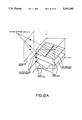
- FIG. 12A is a schematic representation of the perspective ray projection process for producing 2-D images of a 3-D voxel-based object represented within the parallel computing system;
- FIG. 13A is a flow chart of the control computer routine executed by the control computing unit during the low-pass filtering of data stored in the 3-D memory storage array of the parallel computing system;
- FIG. 13B(1) and 13B(2) are a flow chart of the local computer routines executed by each local computing unit during the computer routine of FIG. 13A.
- parallel computing system 1 comprises user interface/display computing unit 2, control computing unit 3, 3-D memory storage array 4, array of local computing units 5, a data transfer network 6 and a data input/output unit 7, and data collection unit 16.
- user interface/display computing unit 2 is realized as a separate host computer system such as, for example, a computer graphics workstation having a high resolution visual display unit, processor, keyboard and other data input devices.
- User interface/display computing unit 2 supports a user interface programs which provide various types of data to control computing unit 3 by way of data transfer means 8.
- memory storage array 4 comprises a plurality of memory storage elements each being capable of storing one or more data elements. These memory storage elements are indexed so that they represent a three-dimensional (3-D) array of NxNxN memory storage elements arranged within 3-D Cartesian coordinate system characterized by x,y, and z orthographic coordinate axes.
- this 3-D Cartesian Space shall be referred to as "C 3 space.”
- array of local computing units 5 comprises N local computing units, each having means for storing one or more local computer programs, and means for locally processing data in accordance with a local computer program.
- each local computing unit is assigned to a group of N 2 memory storage elements in the 3-D memory storage array so that each memory storage element within the sequence of N memory storage elements is accessed by a different local computing unit.
- this memory storage and accessing scheme provides the parallel computing system of the present invention with the ability to access, in a parallel manner, (i) any rectilinear sequence of N memory storage elements extending parallel to any of the three orthographic x,y and z axes in C 3 space; (ii) any sequence of N memory storage elements residing within any pane parallel to one of the principal planes in C 3 space; and (iii) any sequence of N memory storage elements extending through the 3-D memory storage array.
- data transfer means 9 is provided between the array of local computing units and the 3-D memory storage array so that sequences of N accessed data elements can be transferred, in parallel, between the N groups of memory storage elements and the N local computing units.
- the parallel data I/O unit is interfaced with the 3-D memory storage array by way of data transfer means 11.
- data transfer network 6 is operably associated with the N local computing units by way of data transfer means 12.
- the control computing unit provides control data to the data transfer network over control data transfer means 13, and to the data input/output unit 10 over control data transfer means 14.
- the control computing unit provides local computer programs, control data and synchronization signals to each of the N local computing units over data transfer means 15.
- the parallel computing system of the present invention may be configured in a manner different from the system architecture shown in FIG. 1A.
- user interface/display computing unit 2 is shown formed as an integral part of the parallel computing system, rather than as a separate host computing system interfaced with the control computing unit, as shown in FIG. 1A.
- the user interface/display computing unit and the control computing unit can both be realized using a single sequential computing system running both user interface/display computer programs and control computer programs. This feature will be discussed in greater detail hereinafter when describing the illustrative embodiment of the present invention as shown in FIG. 4.
- each memory storage element in (x, y, z) in C 3 space is specified by user interface/display computing unit 2.
- Each memory module contains N 2 memory storage elements or cells, which can store one or more data elements of a selected word length (e.g. 32 bits or more).
- the m(x, y z) location of each memory storage element in physical memory is specified by physical address indices i and j. Together, these indices i, j and k specify the physical address location in physical memory space, which hereinafter shall be referred to as "M 3 space".
- each memory storage element m(x,y,z) in C 3 space uniquely represents one physical memory storage element m(i,j,k) in M 3 space.
- the memory storage and accessing system of the present invention employs a linear "periodic" skewing function which maps each memory storage element m(x,y,z) in C 3 space, into a physical memory storage element m(i, j, k) in M 3 space.
- the Cartesian coordinates x, y, z are mapped into physical address indices, as follows:
- each memory storage module is specified by index k and each memory storage element within the memory module is specified by physical address indices (i, j).
- the following deskewing functions can be applied in order to map the physical address indices of memory storage element m(i,j,k) M 3 space into the corresponding coordinates of memory storage element m(x,y,z) in C 3 space:
- the memory storage elements ⁇ m(x,y,z) ⁇ in C 3 space which are mapped into a single memory storage module in M 3 space reside along diagonal sections having a 45 degree angle with respect to the principal axis planes of C 3 space.
- this skewed memory organization is illustrated in the exemplary 4 ⁇ 4 ⁇ 4 memory storage array of FIG. 3, in particular, in which the diagonal sections are sequentially numbered and grouped "modulo 4."
- N will typically equal 512 or more to provide a high-resolution 3-D data storage buffer.
- each memory storage element is not restricted by the physical address indices i, j, k. Rather, the size of each memory storage element can be much larger than the size of the data element. Thus, a record consisting of a number of data elements can be stored at a single physical memory location m(i,j,k) and be retrieved by repeatedly accessing the memory location m(i,j,k) a number of times. This feature of the present invention will be described in greater detail hereinafter.
- control computing unit 3 When controlled (i.e. coordinated) by control computing unit 3, the array of local computing units can simultaneously access any rectilinear sequence of memory storage elements parallel to anyone of the principal axes, without conflicts between the local computing units.
- beam shall mean any rectilinear sequence of memory storage elements parallel to any one of the principal axes in C 3 space.
- the location of these beams are specified in C 3 space by the user interface/display computing device.
- Cartesian parameters i.e. Cartesian coordinates
- the control computing unit transmits (i.e. broadcasts) these Cartesian coordinates to the array of local computing units.
- the CPU executes a local computer routine which, when coordinated by the control computing unit, achieves parallel data accessing.
- the control computing unit After each local computing unit has generated its set of physical indices i, j, k in M 3 space, the control computing unit then sends synchronization signals to its array of local computing units, which coordinate the array during its access to the specified beam of memory storage elements. Notably, during the parallel memory accessing operation, one local computing unit accesses one memory storage element from its local memory storage module.
- data elements in the beam can be placed on local buses 17.
- the accessed data elements can be held in the local computing units for local processing, and thereafter returned to the same or other memory storage elements in its local memory storage module.
- a number of possible data transfer operations may be performed. For example, an entire beam can be accessed, placed on the local buses, uniformly shifted onto other local buses by way of global data transfer mechanism 6A, and thereafter returned to memory storage locations in M 3 space, which correspond to either the same or different beam of memory storage elements in C 3 space.
- this global data transfer mechanism permits uniform parallel data transfer from one beam, to another.
- one or more memory storage elements can be accessed from the 3-D memory storage array, placed on the local bus(es), and then transferred across adjacent local bus(es) to neighboring memory storage elements, using local data transfer mechanism 6B.
- local data transfer mechanism 6B permits non-uniform data transfer among neighboring memory storage elements.
- global and local data transfer mechanisms 6A and 6B comprise data transfer network 6 illustrated in FIGS. 1A and 1B.
- a beam of memory storage elements can be simultaneously accessed, placed on the local buses, and then transferred through data input/output unit 7 to external data storage device 10.
- data elements from the external data storage device can be transferred through data input/output unit 7, and into an accessed beam of memory storage elements.
- both of these data transfer operations occur under the control of the control computing unit.
- a beam of memory storage elements can be accessed, placed on the local buses, and transferred to data collection unit 18. Thereafter, the control computing unit can transfer the collected data to the interface/display computing unit for storage processing and eventually visual display.
- the distance between any pair of memory storage elements, e.g. m 1 (x 1 ,y 1 ,z 1 ) and m 2 (x 2 ,y 2 ,z 2 ) in Cartesian Space C 3 is defined in terms of the displacement vectors r 1 and r 2 of memory storage elements m 1 (x 1 ,y 1 ,z 1 ) and m 2 (x 2 ,y 2 ,z 2 ) respectively.
- such distance measurements are made from a reference point in the 3-D Cartesian Coordinate System.
- distance r 2 ,1 equals r 2 -r 1 when the data transfer is from m 1 (x 1 ,y 1 ,z 1 ) to m 2 (x 2 ,y 2 ,z 2 ) and the distance r 1-2 equals r 1 -r 2 when the data transfer is from m 2 (x 2 ,y 2 ,z 2 ) to m 1 (x 1 ,y 1 ,z 1 ).
- Cartesian Space C 3 the displacement r 1 of memory storage element m 1 (x 1 ,y 1 ,z 1 ) is measured from a reference point in C 3 , which preferably is selected as the memory storage element m(0,0,0) located at the origin of 3-D Cartesian coordinate system.
- displacement r 2 is also measured from this reference point in the Cartesian coordinate system, as are displacement measures r for all other memory storage elements in the 3-D memory storage array.
- data transfer operations are specified by the user in Cartesian Space C 3 , and prior to execution, must be converted into corresponding parameters expressed in physical memory space M 3 .
- memory storage element m 1 (x 1 ,y 1 ,z 1 ) has a physical memory address in M 3 expressed as m 1 (i 1 ,j 1 ,k 1 )
- memory storage element m 2 (x 2 ,y 2 ,z 2 ) has a physical memory address in M 3 expressed as m 2 (i 1 ,j 1 ,k 1 ).
- displacement l 2 is also measured from this reference point in physical memory space M 3 , as are displacement measures for all other memory storage elements in the 3-D memory storage array.
- the distance l 2 ,1 in physical memory space M 3 can be expressed as:
- a rectilinear beam or sequence of N memory storage elements can be expressed as ⁇ M(x,y,z) ⁇ N in Cartesian Space C 3 , or as ⁇ m(i,j,k) ⁇ N in physical memory space M 3 .
- the parallel computing system of the present invention can access a beam of memory storage elements ⁇ m(x,y,z) ⁇ in a conflict-free parallel manner by simply specifying a pair of coordinates in the principal plane of the coordinate system, which is perpendicular to the orthographic axis that is parallel with the beam of memory storage elements to be accessed.
- a pair of coordinates in the principal plane of the coordinate system which is perpendicular to the orthographic axis that is parallel with the beam of memory storage elements to be accessed.
- the pair of y and z coordinates lying within the y-z plane from which the beam perpendicularly extends must be specified by the user.
- this beam of memory storage elements can be designated by ⁇ m(x,y',z') ⁇ , where y' and z' represent the pair of user specified coordinates defining the point in the y-z plane from which the beam perpendicularly extends.
- a beam of memory storage elements parallel to the y axis of the Cartesian coordinate system can be designated by ⁇ m(x',y,z') ⁇ , where x' and z' represent the pair of user specified coordinates defining the point in the x-z plane from which the beam perpendicularly extend.
- a beam of memory storage elements parallel to the z axis can be designated by ⁇ m(x',y',z) ⁇ , where x' and z' represent the point of user specified coordinate defining the point in the x-y phase from which the beam perpendicularly extends.
- the parallel transfer of data elements from a "source” beam of memory storage elements to a "destination” beam of memory storage elements is a basic operation within the parallel computing system of the present invention.
- data accessed from a "source” beam ⁇ m ns (x,y,z) ⁇ N is transferred to a "destination” beam ⁇ m nd x,y,z) ⁇ N .
- the source beam may be parallel to any one of the three principal axes in the 3-D Cartesian coordinate system.
- each arbitrary source beam and destination beam can be uniquely specified in C 3 space by specifying a set of two Cartesian coordinates (x,y), (y,z) or (x,z) in the principal plane, from which the source or destination beam extends.
- Cartesian specifications or parameters of a source and destination beam designated by CS s and CS d , respectively.
- This distance measure, referenced against m r (o,o,o) in C 3 is referred to as the displacement of memory storage element m ns (x,y,z) or m nd (x,y,z) and is designated by the displacement vector r ns for the n-th memory storage elements along the source beam and r nd for the n-th memory storage element along the destination beam.
- R d ⁇ r nd ⁇ N .
- the x,y, z coordinates of each n-th memory storage element along a source or destination beam increment it will be helpful to consider the case of a source beam extending parallel to the y-axis and a destination beam extending along the x-axis.
- the x and z coordinate values of memory storage elements along the source beam are constant or restricted along the entire beam, and this can be designated as x s ' and z s '.
- the y and z , coordinate values of memory storage elements along the destination beam are constant and can be represented as Y d ' and z d '. It can be easily shown, that for each n-th memory storage element in the specified source and destination beams, the x,y and z coordinate values for each n-th memory storage element along these beams can be expressed in terms of the following displacement vectors:
- each n-th memory storage element m ns (x,y,z) along the exemplary source beam and the corresponding n-th memory storage element m nd (x,y,z) along the exemplary destination beam is given by the distance measure r n expressed in C 3 space as:
- source and destination beams may have any one of nine relative principal orientations in C 3 space, there will be nine corresponding distance equations which can be readily derived in the manner described above.
- the destination beam may spatially coincide with a source beam, and that each n-th memory storage element in the source beam be transferred to the n-th corresponding memory storage element along the destination beam, but which has a different coordinate location.
- parallel data transfer operations are specified using Cartesian specifications CS s and CS d , these data transfer operations are executed in the parallel computing system of the present invention using distance measures defined in physical memory space M 3 . Such distance measures will be developed below.
- each n-th memory storage element m ns (i,j,k) and m nd (i,j,k) along any pair of source and destination beams is specified in physical memory space M 3 by the distance between the memory storage element and a preselected reference memory storage element m r (i,j,k) in M 3 space, which corresponds the reference memory storage element m r (i r ,j r ,k r ) in C 3 space.
- Displacement vector l ns can be expressed in terms of its vector components as follows:
- l ns ⁇ l ns ⁇ N .
- Displacement vector l nd can also be expressed in terms of its vector components as follows:
- the distance l ns , nd between the n-th corresponding memory storage elements along source and destination beams can be defined as the difference of displacement vectors l ns and l nd to provide the following equation:
- a set of N distance measures L can be defined as follows:
- the set of distance measures L in M 3 space can be expressed as:
- the distance measure set L can also be expressed as:
- Expressions (4) and (5) for L above are most important as they provide specifications which can be used by the parallel computing system of the present invention in order to execute the physical operations required during parallel data transfer between a set of source and destination beams specified in terms of CS s and CS d by the user interface/display computing unit.
- each set of physical address indices i ns and j ns can be locally computed and used to access data from memory storage element m ns (i,j,k) during data access from the specified source beam.
- physical address indices i nd and j nd can be derived from a single set of parameters, such as CS d , then these Cartesian parameters can be transmitted to all local computing units and each set of physical address indices i nd and j nd can be locally computed and used to transfer uniformly shifted data to memory storage element m nd (i,j,k) during data transfer to the specified destination beam.
- physical address indices i nd and j nd for all values of n can also be locally computed using (a) Cartesian parameters CS d specifying a user selected destination beam, and (b) the linear skewing function specified above.
- the specific variants of the linear skewing function required during this computational step depend on the constrained coordinate pairs of CS s and CS d , and will be described in greater detail hereinafter.
- distance k n has been found to equal a constant measure for all value of n, thereby permitting the use of a global data transfer mechanism in the parallel computing system of the present invention.
- accessing and transfer subsystem of the present invention it is helpful to first note that user specified source and destination beams can be spatially arranged in C 3 space in any of one of nine possible coordinate orientations expressed relative to the principal coordinate axis. For purposes of illustration, the case where the source beam is parallel to the x-axis and the destination beam is parallel to the y-axis, is considered.
- Cartesian parameter CS s comprises the coordinate pair (y s ', z s '), where y s ' and z s ' are each constant for all values of x s .
- Cartesian parameter CS d comprise the coordinate pair x d ', z d ', where x d ' and z d ' are each constant for all values of y d .
- these system components are structured about a system bus 27, N local buses 28 indexed k-o, 1, 2, . . . N-1, and a control and synchronization bus 29.
- each k-th local module comprises a k-th local computing unit 30, a k-th local data storage module 31 having N 2 memory storage elements or cells indexed by physical address indices i, j, as hereinbefore described, and a k-th local bus interface controller 32.
- each k-th local computing unit is connected to the k-th local memory storage module, the I/O unit, the data collection unit, the global data transfer mechanism and the k-th and (k+1)-th local bus interface controllers.
- the interconnection of each k-th local computing unit with the k-th and (k-1)th local bus interface controllers permits each local computing unit to transfer data elements to any one of its three neighboring local computing units.
- each local computing unit can be realized by any sequential computer capable of running local computer programs and communicating with its environment.
- the local computer programs e.g. routines
- routines which will be described in greater detail hereinafter, are preferably complied in user interface/display computing unit 23, or alternatively in the control computing unit 22.
- each local computing unit is implemented by a Reduced Instruction Set Computer (RISC) having associated program memory realized as cache memory, and independently accessible data storage memory, realized as a RAM device.
- RISC Reduced Instruction Set Computer
- the reduced instruction set computer is a high performance 32-bit microprocessor, such as the R3051 RIS controller commercially available from Intelligent Device Technology (IDT).
- IDTT Intelligent Device Technology
- 4K-byte cache program memory is provided to each microprocessor.
- the cache memory is used to store local computer programs downloaded from the control unit by way of computing system bus 27.
- each local memory storage module is implemented by a single dynamic RAM memory chip of 64K ⁇ 32 bits.
- the size of the data element can be easily extended by stacking up more than one memory storage module, so that a desired sequence of bits in each memory storage element can be locally addressed in a sequence selected by the local computing unit.
- the physical address of each memory storage element m(i,j,k) remains unchanged in its memory storage module, although there is a need to provide a simple memory management unit to each local memory storage module in order to handle the sequence of data elements stored at each memory storage element m(i,j,k). This option in described in greater detail in connection with the description of FIGS. 13A through 13B(2).
- control computing unit 22 can be realized by any sequential computer capable of running control computer programs (e.g. routines) and communicating with its environment.
- control computing unit is implemented by a RISC computer having associated program memory and independently accessible data storage memory realized as a RAM device.
- Control computer programs which will also be described in greater detail hereinafter, are complied in the user interface/display computer unit and are then downloaded into the program memory by way of system bus 27.
- the function of the user interface/display computing unit is to interact with the parallel computing system 20.
- the interface/display computing unit may be used to interface parallel computing system 20 with another computer system.
- the user interface/display computing unit supplies to the system, information specifying particular computing and display tasks to be performed.
- the user interface/display computing unit is a 3-D graphics workstation, commercially available from Sun Microsystems, Silicon Graphics, etc.
- the function of this workstation is to run user interface programs (e.g. routines), compile control and local computer programs, and provide an interactive environment and graphics utilities (e.g. Windows).
- the graphics workstation includes a graphics display and shading unit in order to display 2-D projections from 3-D volume renderings stored within the 3-D memory storage array of the system.
- control computing unit 22 can be incorporated within the control computing unit, as illustrated in FIG. 4.
- control computing unit is preferably realized as a graphics workstation, and the user interface/display and control programs are stored in and run on the sequential computer of the graphics workstation.
- the first side of each k-th local I/O port is connected to the k-th local data bus, and the second side thereof is operably connected to one port on the "system" side of the N/M data multiplexing device by way of electrical conductors 37.
- one or more ports 38 are provided and are operably connected with an external data storage system 39.
- local I/O ports 21 and data multiplexing device 35 are controlled by control signals sent from I/O controller 36 over control bus 40.
- parallel I/O unit 25 provides an interface between local data buses 21 and a external data storage system 39 which functions as a data file system.
- data collection unit 24 provides a feedback mechanism for (i) transferring data results from the local computing units to the control computing unit, as well (ii) individual data (e.g., control flags, semaphores) from the control computing unit to different local computing units.
- This feedback mechanism permits each local computing unit to indicate that a parallel operation has been completed, and to write non-uniform data from the control computing unit to different local units.
- data collection unit 24 comprises an arrangement of N dual-port data buffers 41, in which each dual-port data buffer is operably connected to one local computing unit by its local data bus.
- the N dual port buffers are accessible in parallel by the N local computing units by way of the N local buses, and sequentially accessible by the control computing unit (or optionally by the interface/display computing unit) by way of the system bus.
- system bus 27 and control and synchronization bus 29 can be implemented by a standard bus technology (e.g., VME and VMS bus family).
- bus technology e.g., VME and VMS bus family.
- VME and VMS bus family For details regarding bus technology, reference can be made to pgs. 143-149 of "Structural Computer Organization" by Andrew Tanenbaum.
- these two buses create a communication environment between the control computing unit and the array of local computing units, and also between the user interface/display computing unit and the central computing unit. For example, commands and parameters furnished by the control computing unit are broadcast over the system bus to each of the local computing units.
- the system bus is also utilized during the loading of programs to the memories of the local computing units.
- the control and synchronization bus runs independently of the system bus, and is used by the control computing unit for low-bandwidth control communication and synchronization of the local computing units, the global data transfer mechanism, parallel data I/O unit, and the data collection unit.
- each k-th local bus 28 comprises 32 data lines 28A, 17 address lines 28B, and a required number of control lines 28C.
- Each local bus can be realized using standard VME bus technology, the advantage of which is its reliability, availability and variety.
- Each k-th local bus is governed by the k-th local bus interface controller 32.
- each local bus interface controller 43 is realized by integrating local bus control logic circuitry 43 and a triad of dual-port buffers 44, 45 and 46, each having associated address logic.
- Local interface control logic circuitry 43 can be realized using a standard VME interface controller (e.g., VICO68 by Cypress Semiconductors).
- the local interface control logic circuitry provides all VME bus control functions operating at a rate of up to 40 Mbytes per second.
- Such local bus control functions include, for example, (i) data transfer, (ii) bus arbitration, and (iii) interrupt control.
- Data transfer functions on each local bus include ordinary read and write operations performed between the various elements operably connected to each k-th local bus in the parallel computing system, namely the k-th local computing unit, the k-th local memory storage module, the first, second and third dual-port buffers in the k-th local bus interface controller, the data collection buffer, the parallel data I/O unit, and the global data transfer mechanism bus arbitration on each local bus is performed using master/slave relationships.
- each k-th local computing unit acts as master element when attempting to communicate (i) with neighboring local computing units through the first, second or third dual-port buffers, (ii) with the k-th local memory storage module, (iii) with the parallel I/O port, and (iv) with the data collection buffer.
- each local computing unit acts as a slave element when it is addressed by the parallel I/O unit, the global data transfer mechanism, and any one of the dual-port buffers of either the k-th or the (k-1)th local bus interface controllers.
- Each k-th local memory storage module acts as a slave element in all communication modes.
- each k-th local memory storage module can be addressed by the k-th local computing unit and also by the k-th I/O port of the parallel data I/O unit.
- each k-th dual-port buffer in the data collection unit acts as a slave element and is addressed by the k-th local computing unit.
- Each k-th local I/O port of the parallel data I/O unit is addressed by the k-th local computing unit and acts as a slave element during data output operations.
- each k-th local I/O port acts as a master element and addresses the k-th local computing unit or the k-th local memory storage module.
- Each k-th bidirectional terminal of the global data transfer mechanism acts as a master element addressing the k-th local computing unit during all phases of global data transfer operations.
- the first, second and third dual-port buffer of each k-th local bus interface controller acts as a slave element and is addressed by the k-th local computing unit and the associated dual-port buffers of the (k+1)th and (k-1)th local bus interface controllers.
- the bus arbitration process operates as follows. Whenever two competing master elements attempt to concurrently access the k-th local bus, the local bus control logic circuitry of the k-th local bus interface controller grants an access to the master element having the higher priority, in accordance with a priority table preprogrammed with the local bus interface controller.
- local data transfer network 47 comprises the array of N local computing units, local buses 28, and local bus interface controllers 32, which interface adjacent local buses in a manner to be described in detail hereafter.
- the function of the local data transfer network is to permit each k-th local computing unit to selectively transfer an accessed data element stored in memory storage element m(i c ,j c ,k c ), i.e., at m(x c ,y c ,z c ), in its local memory module, to any one of the 26 memory storage elements having x, y and z cartesian coordinates selected from the set defined by ⁇ x c ⁇ 1, y c ⁇ 1, z c ⁇ 1 ⁇ .
- This local data transfer capability of the parallel computing system of the present invention is decentralized in that it does not operate under the control of the control computing unit and is essentially asynchronous during its operation. Owing the unique structure of the memory storage and accessing subsystem of the present invention, the above-defined 26 connected data transfer capability of the local data transfer network requires that each k-th local computing unit only transfer an accessed data element from its local memory module to up to three adjacent local computing units associated with the k ⁇ 1, k ⁇ 2, k ⁇ 3 memory storage modules. As will be more full appreciated hereinafter, the decision to transfer any data element(s) residing in a specified memory storage module remains strictly with the local computing unit managing the local memory storage module in which its specified data element is stored.
- each k-th local bus is physically interfaced with adjacent k ⁇ 1 local buses by way of dual-port buffers 44 of the k-th bus interface controller.
- the data and address lines of the first port of first dual-port buffer 44 are connected to the data and address lines of the k-th local bus, whereas the data and the address lines of the second port of the first dual-port buffer are connected to the data and address lines of the (k-1)th local bus.
- the data and address lines of the first port of second dual-port buffer 45 are connected to the data and address lines of the k-th local bus, whereas the data and the address lines of the second port of the second dual-port buffer are connected to the data and address lines of the (k-1)th local bus.
- the data and address lines of the first port of third dual-port buffer 46 are connected to the data and address lines of the k-th local bus, whereas the data and the address lines of the second port of the third dual-port buffer are connected to the data and address lines of the (k-1)th local bus.
- the data, address and control lines of the k-th local bus control logic circuit i.e., VME bus controller
- VME bus controller the data, address and control lines of the k-th local bus.
- Transferring data elements between a k-th "source” local computing unit and a (k ⁇ k n ) "destination" neighboring local computing unit is achieved using the local buses, dual-port buffers 44, 45 and 46 and local bus control logic 43 disposed between these local computing units.
- dual-port data buffers 44, 45, and 46 each utilize special address logic schematically distributed in FIG. 4D(2).
- each k-th local computing unit (acting as a source) and surrounded by its six neighboring local computing units (any one of which can be a destination) is assigned a relative local address binary "00" which is indicated by the two last significant bits on the address lines of the k-th "source” local bus.
- the right-hand neighbors of the k-th local computing unit are assigned the following binary relative local addresses.
- each first dual-pont buffer in the neighborhood of the k-th local computing unit is assigned, relative local address equal to the local relative address of one of the six neighboring local computing units.
- each k-th local computing unit is mediated from its six neighboring local computing units by a designated dual port buffer assigned the same relative local address value.
- each dual-port buffer performs three primary functions:
- the local bus interface controllers resolve local bus conflicts during concurrent local data transfer across the local data transfer network.
- bus contention Upon the occurrence of bus contention at a local bus interface controller, where two data elements are being transferred along the same data bus lines, one data element will be automatically delayed while buffered in the dual-port buffer triad of the local bus interface controller, until the other data element is removed from the required local bus.
- the local data transfer network involves primarily the local computing unit acting as the "source” of data to be transferred, and the function of the "destination" local computing unit is merely to receive the transferred data element.
- This data reception process is initiated by an interrupt signal generated by the local bus address logic in the dual-port buffer feeding the destination local computing unit.
- the function of the control computing unit is to allocate time slots, during which local computing units are permitted to participate in a particular local data communication session. Preferably, these time slots will be allocated according to the demand for local data transfer in each application.
- global data transfer network 49 comprises the array of local computing units 30, local buses 28, global data transfer mechanism 26, control computing unit 22, system bus 27, and control and synchronization bus 29.
- the function of the global data transfer network is to selectively transfer a sequence of N data elements from a specified source beam in the 3-D memory storage array, to a specified destination beam therein.
- the global data transfer network uniformly transfers each data element in the accessed source beam over a uniform distance k n in M 3 space, to the accessed destination beam.
- each data element in each k-th memory storage element of a source beam is moved across the same number of local memory storage modules during its transfer to the corresponding memory storage element in the destination beam. Accordingly, the function of global data transfer mechanism 26 is to move in a parallel fashion, N data elements over a uniform distance k n under the control of the central computing unit.
- the global data transfer network is best illustrated by describing its operation during the simultaneous transfer of N data elements from a source beam to a destination beam specified in C 3 space. This process can be best illustrated by referring to the global data transfer network of the present invention schematically represented in FIGS. 4, 4C and 4E(1), and the computer routines illustrated by the flowcharts represented in FIGS. 5, 5A, 5B and 5C.
- the first step in this parallel data transfer process involves the user specifying the source and destination beams in terms of Cartesian parameters CS s and CS d .
- Cartesian parameters CS s and CS d are generated at the user interface/display computing unit and then transferred over the system bus, to the control computing unit.
- the control computing unit uses Cartesian parameters CS s and CS d and expression 6, to calculate uniform distance measure (i.e., memory module shift) k, which is then buffered.
- the control computing unit then broadcasts Cartesian parameters CS s over the system bus, to the array of local computing units.
- Cartesian parameters CS s and CS d are generated at the user interface/display computing unit and then transferred over the system bus, to the control computing unit.
- uniform distance measure i.e., memory module shift
- each k-th local computing unit uses Cartesian parameters CS s to compute physical address indices i and j, then accesses memory storage element m(i,j,k) along the source beam. Then as indicated at Block D in FIG. 5B, the control computing unit transmits synchronization signal over the control and synchronization bus to the local computing units. Then, at Block D in FIG. 5C, each k-th local computing unit places the accessed data element on the k-th local bus.
- the control computing unit transmits module distance k, and timing control signals over the control and synchronization bus, to the global data transfer mechanism, which in turn, enables the data element on each k-th local bus to be transferred into the k-th I/O buffer unit in the global data transfer mechanism.
- the global transfer mechanism automatically transfers (i.e., shifts) each data element in the k-th local I/O buffer port to the (k+ k)th local I/O buffer port.
- the control computing unit transmits control signals over the control and synchronization bus to the global data transfer mechanism, so that it transfers the data element from each k-th local I/O buffer port to the k-th local computing unit.
- the control computing unit then broadcasts Cartesian parameters CS d over the system bus to each local computing unit.
- the Cartesian parameter CS d is received by each local computing unit, and at Block G indices i and j are computed for the memory storage element m(i,j,k) along the destination beam.
- each k-th local computing unit accesses memory storage element m(i,j,k) in its local memory storage module, and then stores data element D k+ k therein.
- each global data transfer unit comprises a global data transfer subunit for each bit in the eight bit local bus.
- Each subunit is operably connected to the corresponding data lines of two different local buses over which data bits d o and d 1 can be transferred.
- each subunit has left and right data bit transfer ports 51 and 52, which are operably connected to correspondingly right and left data bit transfer ports of the adjacent subunit, respectively, by way of conductive pathway pairs 53A, 53B and 54A, 54B, as shown in FIG. 4E(2).
- each subunit of exemplary embodiment comprises a switching matrix 55 having 2 rows and 2 columns of switching element 56, and two I/O buffer circuits 57A and 57B, and control logic circuitry 58 operably associated with its switching matrix and the control computing unit. As shown in FIG.
- each I/O buffer circuit comprises an I/O buffer 59, an activatable switching gate g x , an input line driver 61, an output line driver 62, an I/O line 63, connected to the data line of the k-th local bus.
- each I/O buffer circuit comprises an input line 64 and an output line 65 connected to the input and output line drivers 61 and 62, respectively.
- switching gate gx is connected across the output of output line driver 62 and the input of input line driver 61.
- each switching element 56 comprises a combination of four conventional switching gates g 1 , g 2 , g 3 and g 4 configured as shown to provide a pair of row and column data bit transfer pathways, in which only one of these pathways can be selected by control logic circuitry 58 which controls the operational status of these switching gates.
- each row data bit transfer pathway has a designated row input line 66 and a row output line 67
- each column data bit transfer pathway has an upper column line 68 and a lower column line 69.
- module distance i.e.
- control logic circuitry of each subunit generates a set of switching matrix control signals including (i) I/O buffer control signals provided to I/O buffer circuitry 57A, 57B; (ii) left and right rows of switching element control signals provided to switching gates g 1 , g 3 and g 2 , g 4 , respectively, and (iii) extended shift cycle control signals provided to the switching gate g x in each of I/O buffer circuits in order to bypass I/O buffer 59.
- the set of switching elements (J m ,n) and the I/O input circuits are configured as follows.
- the row to which each switching element is assigned is designated by index m
- the column is designated by index n.
- the input line of each I/O buffer circuit is connected to the row input lines of the switching elements in the column associated with its I/O buffer circuit.
- the output line of each I/O buffer circuit is connected to the output lines of the switching elements in the column associated with its I/O buffer circuit.
- the upper column line of switching element J 1 ,2 is internally connected to the lower column line of switching element J 1 ,1 in the left contiguous global data transfer subunit.
- This interconnection provides for a bidirectional transfer of data element bits over a module distance equal to ⁇ 1 in M 3 space.
- the upper column line of switching element J 1 ,1 is externally connected to the lower column line of switching element J 1 ,2 in the left contiguous global data transfer subunit.
- This interconnection also provides for bidirectional transfer of data element bits over a module distance equal to ⁇ 1 in M 3 space.
- the upper column line of switching element J 2 ,2 is externally connected to the lower column line of switching element J 2 ,1 in the left contiguous global data transfer subunit.
- the interconnection provides for bidirectional transfer of data element bits over a module distance equal to ⁇ 2 in M 3 space.
- the lower column line of switching element J 2 ,2 is externally connected to the upper column line of switching element J 2 ,2 in the right contiguous global data transfer subunit. This interconnection also provides for bidirectional transfer of data element bits over a module distance equal to ⁇ 2 in M 3 space.
- control logic circuitry 58 in the global data transfer mechanism receives control signals from the control computing unit.
- these control signals are provided to the I/O buffer circuits by the control logic circuitry of each subunit, which permits each bit of each data element on each k-th local bus to be transferred to a buffer in a respective I/O buffer circuit.
- Each data element bit in each I/O buffer circuit is then placed on the row input lines of all the switching elements associated with its I/O buffer circuit.
- the control logic circuitry in each subunit activates switching elements (J 2 ,m) along the second row only, by providing switching control signal to gates g 2 and g 4 .
- This control operation causes data element bit d o on the first row input line of subunit S 1 to the lower column line thereof.
- data element bit d 1 on the second row input line is transferred through switching element J 2 ,2 of subunit 50A to the lower column line thereof;
- data element d 2 on the third row input line is transferred through switching element J 2 ,1 of subunit 50B to the lower column line thereof;
- data element bit d 3 on the fourth row input line is transferred through switching element J 2 ,2 of subunit 50B to the lower column line thereof.
- each data element bit is placed on the row output line of the switching element since switching control signals are continually being provided to switching gates g 4 .
- each data element bit on its low output line is moved to the terminal of its destination I/O buffer.
- control logic circuitry in each subunit activates switching elements (J 1 ,m) of the first row only by providing switching control signals to gates g 2 and g 4 .
- This control operation causes element bit on the first row input line of subunit 50A to be transferred through switching element J 1 ,1 to the lower column line thereof.
- data element bit d 1 on the second row input line is transferred through switching element J 1 ,2 of subunit 50A to the lower column line thereof;
- data element bit d 2 on the third row input line is transferred through switching element J 1 ,1 of subunit 50B to the lower column line thereof;
- data element bit d 3 on the fourth low input line is transferred thereon; switching element J 1 ,2 of subunit 50B to the lower column line thereof.
- the exemplary embodiment of the global data transfer mechanism described above contained four I/O buffer units and two data element switching matrices, this mechanism can be easily extended to include any number of I/O buffer units and switching matrices necessary to facilitate uniform global data transfer within any size 3-D N ⁇ N ⁇ N memory storage array.
- the number of I/O buffer units will be selected to equal the number of local buses, which will typically equal N, and the number of I/O buffer circuits comprising each k-th I/O buffer unit will be selected to equal the width of the local buses in the parallel computing system.
- the number of global data transfer units employed in any particular embodiment will be selected on the basis of several considerations.
- the parallel computing system of the present invention may employ one of several suitable "coordination" techniques.
- One coordination technique utilizes performance data empirically acquired from the individual local computing units in order to determine when a computational routine (i.e. task) has been completed by all the local computing units in the array.
- the coordination technique involves empirically determining for each local computing unit, the longest "execution time” required to complete specific computational tasks (i.e., specific local computer routines) upon "worst case” data sets. These "execution times” are then listed in a local computer routine performance table, which is stored in the data storage memory of the central computing unit. Then, whenever the control computing unit reaches an instruction in one of its control computing routines which indicates local computer coordination is required, the control computing unit carries out the following local computer coordination routine. First, the central computing unit sets an internal timer and then broadcasts over the system bus a command which initiates the execution of a predesignated local computer routine requiring coordination.
- the internal timer within the central computing unit, measures the elapsed time. Prior the elapsed time reaching the "execution time,” the control computing unit may execute other routine not involving coordination. However, only when the elapsed time equals the "execution time” the control computing unit proceeds to the next routine requiring coordination. This local computer coordination process will be further illustrated in FIGS. 5A through 5C, 8A and 8B, and others.
- Another coordination technique that may be employed involves each local computing unit generating a task completion flag upon completion of its assigned task, and to store this flag in the k-th dual-port buffer in the data collection unit. Periodically, the control computing unit searches for flags in the data collection unit to determine if all local computing units have completed their tasks. When all local computing units have completed their routines, the control computing unit proceeds to the next routine requiring coordination.
- each printed circuit board supports the following system components: the sixteen local computing units, the sixteen local memory storage modules, the sixteen local bus interface controllers, the sixteen local buses, the sixteen local I/O ports, one parallel I/O unit, the sixteen dual-port buffers of the data collection unit, and the global data transfer unit comprising thirty-two subunits operably interconnecting the data lines of the sixteen local buses.
- These sixteen boards are connected to a central printed circuit board which supports the central computing unit, the interface to the user interface/display computing unit, and the system bus controller.
- the parallel computing system of the invention can be easily reconfigured into one of several parallel computing configurations. This is achieved by downloading identical or different local computing programs into the program memory of each Local Computing Unit, downloading an appropriate control program into the Control Computing Unit, and an UID program into the UID computing unit.
- STMD single task multiple data
- MIMD multiple instruction multiple data
- each local computing unit has a specialized task and thus its own individual program. In either of the configurations, the entire system is coordinated by the control computing unit.
- a hybrid configuration can be achieved by combining any combination of STMD and MIMD configurations throughout the parallel computing system.
- the data collection buffer serves as a configuration pool for storing different local programs.
- Each of the described parallel computing programs comprises an interface display program, a control program and a local program residing in the UID computing unit, the control computing unit, and the local computing unit respectively, in order to locally generate physical addresses indices i,j and then access the k-th memory storage element m(i, j, k) along a specified beam.
- FIGS. 6A through 6F parallel accessing of data storage elements along beams parallel to the three orthographic axes are illustrated.
- a beam of memory storage elements parallel to any of the principal axes in C 3 space can be accessed in a parallel fashion by the parallel computing system of the present invention.
- a set of three computer routines illustrated in FIGS. 6A through 6C, are synchronously executed within the parallel computing system utilizing the coordination technique described in detail above.
- the first step in the computer routine executed by the interface/display computing unit involves the user providing a Cartesian specification of the beam of memory storage elements to be accessed in the 3-D memory storage array.
- user input specifications CS will fall within three distinct groups, namely: (i) a first group in which two coordinates are restricted, (i.e.,(x,y),(x,z) or (y,z); (ii) a second group in which one coordinate is restricted (i.e. x, y or z); and (iii) a third group in which no coordinate is restricted.
- Cartesian parameters CS will be selected from the first group of Cartesian specifications.
- second step of the routine involves sending the user specified Cartesian parameters CS over the system bus to the control computing unit.
- the first step in the computer routine executed by the control computing unit involves receiving Cartesian parameters CS from the interface/display computing unit, and then broadcasting these parameters over the system bus to the array of local computing units, while sending synchronization signals over the control and synchronization bus.
- the first step in the computer routine by each k-th local computing unit involves synchronously receiving the broadcasted Cartesian parameters CS.
- the second step of the routine involves calculating the physical address indices i and j using a linear deskewing function.
- each k-th local computing unit accesses the memory storage element m(i,j,k) specified by physical address indices i,j in the k-th memory storage module. This operation is carried out in a coordinated manner by the array of local computing units so as to access a rectilinear sequence of memory storage elements extending along a beam defined by user-specified Cartesian parameters CS.
- i and j are directly known without any computation.
- N storage elements residing within a plane parallel to any one of the principal planes in C 3 space can be accessed by carrying out a parallel data access operation in a manner described below.
- a set of three computer routines illustrated in FIGS. 6A through 6C are synchronously executed within the parallel computing system utilizing the coordination technique described in detail above.
- the computer routine executed by the user interface/display computing unit involves the user providing a Cartesian specification of the plane of memory storage elements to be accessed in the 3-D memory storage array. As illustrated in FIG. 6A, these Cartesian specifications CS will be selected from the second group of Cartesian parameters. These user-specified Cartesian parameters CS are transferred over the system bus to the control computing unit.
- the computer routine executed by the control computing unit performs essentially the same Cartesian parameter reception and broadcasting functions, as well as the local computing unit coordinating function described hereinabove.
- N memory storage elements residing within the 3-D array can be accessed by carrying out a parallel data access operation in the manner described below.
- a set of three computer routines illustrated in FIGS. 6A through 6C are synchronously executed within the parallel computing system utilizing the coordination technique described in detail above.
- the computer routine executed by the user interface display computing unit does not involve the user specification. Instead, the specification of those N memory storage elements are selected by the local computing unit.
- the computer routine executed by the control computing unit performs essentially the same Cartesian parameter reception and broadcasting functions, as well as the computing unit coordinating functions described hereinabove.
- each local computing unit involves synchronously receiving the new broadcasted set of Cartesian parameters, and then freely selects any set of two Cartesian coordinate values, i.e., (x,y), (y,z), or (x,z). Using its selected set of Cartesian coordinates, each local computing unit computes physical address indices i and j in a manner described above. This operation is carried out in a coordinated manner by the array of local computing units so as to access the locally specified sequence of N memory storage elements extending through the 3-D memory storage of the parallel computing system.
- the user will either desire or require the ability to transfer or exchange data elements among 6-connected, 18-connected or 26-connected neighboring memory storage elements viewed from C 3 space.
- Examples of such applications include image processing of 3-D medical images, finite element analysis, physical simulations and the like.
- image processing of 3-D medical images finite element analysis, physical simulations and the like.
- massive amounts of data elements there is also a great need to achieve such types of data transfer in a highly parallel fashion. Owing to the structure and function of the memory storage and accessing capability of the parallel computing system of the present invention, such parallel data transfers can be easily accomplished in a high speed fashion transparent to the user.
- FIG. 7A a schematic representation is provided in order to illustrate the relationship between (i) the location (i.e. position) of 6 connected neighboring memory storage elements in C 3 space and (ii) the physical addresses of corresponding memory storage elements in M 3 space.
- Transferring data elements from any one of these 6-connected neighboring memory storage elements to the central memory storage element, or vice versa can be achieved using either the local data transfer network or the global data transfer network described above.
- the global data transfer network is used, the initiation for the data transfer will originate from the control computing unit and will result in a uniform data transfer involving each and every local computing unit as hereinbefore described.
- FIG. 7B a schematic representation is provided in order to illustrate the relationship between (i) the location (i.e., position) of 18-connected neighboring memory storage elements in C 3 space and (ii) the physical addresses of corresponding memory storage elements in M 3 space.
- FIG. 7C a schematic representation is provided in order to illustrate the relationship between (i) the location (i.e.,position) of 26-connected neighboring memory storage elements in C 3 space and (ii) the physical addresses of corresponding memory storage elements in M 3 space.
- this method can be carried out N 2 times, to exchange 6-connected data elements throughout the entire 3-D memory storage array.
- the object of this operation is to transfer in parallel data elements accessed from 6-connected neighboring memory storage elements, to their N associated "central” memory storage elements reading along a specified beam, so that each local computing circuit associated with one of the "central” memory storage elements along the beam can access the "6-connected" data elements for processing.
- the N "central" memory storage elements reside along a beam (i.e. rectilinear sequence) which is designated as RS0.
- the user interface/display unit executes a computer routine to provide a command which initiates the 6-connected global data exchange process and the specific data processing operation to be performed at each of the local computing units associated with each "central" memory storage elements in C 3 space.
- the central computing unit initializes the coordinate variables x,y 0 which specify the central memory storage elements m(x 0 ,y 0 ) residing along the beam RS0.
- central memory storage elements m(x 0 ,y 0 ) are where neighboring data elements are to be transferred (i.e., collected), location of these central memory storage elements are specified by Cartesian parameters CS d , as hereinbefore described.
- Cartesian parameters CS s for source beams RS0, RS1, RS2, RS3 and RS4 will change each time the central destination beam RS0 is changed, during each of the N 2 cycles in the 6-connected global data exchange process.
- the control computing unit calls from its program memory, the global data transfer (GDT) routine of FIG. 5B described in great detail above, which in turn initiates the GDT subroutine of FIG. 5C carried out in the array of local computing units.
- GDT global data transfer
- Cartesian parameters CS s and CS d are passed to the GDT routine in the control computing unit and k is passed to global data transfer mechanism as part of the execution of the global data transfer routine for source and destination beams RS0 and RS0.
- the control computing unit calls from its program memory the global data transfer (GDT) routine of FIG. 5B described in great detail above, which in turn initiates the GDT subroutine of FIG. 5C carried out in the array of local computing units.
- GDT global data transfer
- Cartesian parameters CS s and CS d are passed to the GDT routine in the control computing unit and k is passed to global data transfer mechanism as part of the execution of the global data transfer routine for source and destination beams RS4 and RS0.
- GDT global data transfer
- Cartesian parameters CS s and CS d are passed to the GDT routine in the control computing unit and k is passed to global data transfer mechanism as part of the execution of the global data transfer routine for source and destination beams RS3 and RS0.
- the control computing unit calls from its program memory the global data transfer (GDT) routine of FIG. 5B described in great detail above, which in turn initiates the GDT subroutine of FIG. 5C carried out in the array of local computing units.
- GDT global data transfer
- Cartesian parameters CS s and CS d are passed to the GDT routine in the control computing unit and k is passed to global data transfer mechanism as part of the execution of the global data transfer routine for source and destination beams RS0 and RS0.
- the control computing unit calls from its program memory, the global data transfer (GDT) routine of FIG. 5B described in great detail above, which in turn initiates the GDT subroutine of FIG. 5C carried out in the array of local computing units.
- GDT global data transfer
- Cartesian parameters CS s and CS d are passed to the GDT routine in the control computing unit and k is passed to global data transfer mechanism as part of the execution of the global data transfer routine for source and destination beams RS2 and RS0.
- the control computing unit calls from its program memory the global data transfer (GDT) routine of FIG. 5B described in great detail above, which in turn initiates the GDT subroutine of FIG. 5C carried out in the array of local computing units.
- GDT global data transfer
- Cartesian parameters CS s and CS d are passed to the GDT routine in the control computing unit and k is passed to global data transfer mechanism as part of the execution of the global data transfer routine for source and destination beams RS1 and RS0.
- each local computing unit performs the required processing operation upon the collected data set to obtain a computed result.
- each local computing unit locally determines the physical addresses i and j, accesses memory storage element m(i,j,k) and stores therein the computed result.
- the computed result may be stored in the main memory of the local computing unit.
- the central computing unit increments by +1, the x 0 coordinate of the Cartesian parameters CS d which specify the location of the central memory storage elements along the destination beam RS0 for the subsequent 6-connected global data exchange cycle.
- the control computing unit proceeds to Block C, and then performs the above-described steps indicated at Blocks C through O then at Block P, the central computing unit increments by +1 the x 0 -coordinate of the Cartesian parameters CS d .
- the control computing unit resets the x 0 coordinate (i.e.
- each "data element" may represent.
- these data types can be grouped into at least five principal classes: (1) scaler type data; (2) vector type data; (3) hybrid vector/scaler; (4) purely numeric type data and (5) symbolic type data such as alphanumeric character and strings thereof.
- each individual data element in C 3 space may be of either the scaler, vector or hybrid vector/scaler type.
- scaler data will be used.
- vector data will be used when both such types of properties are to be represented.
- each individual data element in C 3 space will be of the hybrid vector/scaler type in order to represent the material structure at specific points in space, as well as the acting forces at those points.
- each individual data element in C 3 space will be of the purely numeric type.
- the 3-D organization of such type of data elements will be solely for the purpose of efficient data storage, accessing and processing.
- each individual data element When concerned with symbolic applications, such as storage, retrieval and analysis of textually demonstrable information, (e.g. alphanumeric strings) and recorded speech in C 3 space, each individual data element will be of the symbolic data type. In such cases as well, the 3-D organization of such type of data elements will be solely for the purpose of efficient data storage, accessing and processing.
- scaler type data such as volume element (i.e. local data) can be generated by a 3-D medical scanner such as a CAT or NMR Scanner.
- a 3-D medical scanner such as a CAT or NMR Scanner.
- voxel-based images of 3-D objects in C 3 space can be generated within the parallel computing system hereof using a "parallel voxelization process”.
- vector and hybrid vector/scaler type data elements can be generated within a separate, external computer graphics workstation interfaced with parallel I/O unit 25, and then loaded into the 3-D memory storage array under the control of the control computing unit.
- types of data elements can be generated within the parallel computing system of the present invention.
- each k-th local computing unit can access the voxel in the k-th I/O buffer port and then access memory storage element m(i,j,k) corresponding to m(x,y,z) along beam M 1 , in C 3 space, as each such memory storage element is contained within the local memory storage module of the k-th local computing unit.
- the k-th local computing unit is unable to access memory storage element m(i,j,k) corresponding to m(x,y,z) along beam M 2 in C 3 space, as each such memory storage element is not contained within the local memory storage module of the k-th local computing unit, owing to the fact of the linear skewing scheme employed in the memory storage and accessing system of the present invention.
- voxels of each beam B in the 3-D image can be properly transferred to its spatially correct memory storage element location in C 3 space of the 3-D memory storage array by first uniformly shifting each voxel in each beam a predetermined module distance k using the global data transfer mechanism, and then move the shifted beam of voxels into its spatially correct beam of memory storage elements in the 3-D memory storage array.
- This data transfer process will be described below with reference to FIGS. 9A and 9B.
- the user interface/display computing unit sends an I/O data transfer command C I/O over the system bus to the control computing unit.
- Cartesian parameters CS specify both the location of the beam of voxels in the 3-D image relative to a coordinate system isometric with the internal coordinate system of C 3 space.
- the control computing unit sends control signals over the control and synchronization bus to the I/O controller in order to initiate an input of beam of voxels with the N local I/O buffer ports of the I/O unit.
- the control computing unit sends a control signal to the local I/O buffer ports and the control logic circuitry of the global data transfer mechanism to move the beam of voxels from the local I/O buffer ports to the I/O buffer circuits of the global data transfer mechanism.
- the control computing unit sends over the control and synchronization bus, timing control signals and module distance k to the global data transfer mechanism.
- the global data transfer mechanism executes the global data shift upon the buffered voxel beam.
- the control computing unit sends control signals over the control and synchronization bus to the global data transfer mechanism and the local computing units in order to transfer the uniformly shifted voxel to the local computing units.
- the subroutine performed by each of the local computing units during this step is illustrated in FIG. 9C.
- the first voxel beam of the 3D voxel image is successfully loaded with the 3-D memory storage array.
- each local computing unit in the array can generate data elements in accordance with a specified set of rules and then stored in local memory storage modules in a parallel manner.
- 3-D voxel-based images of geometrically represented objects can be generated within the parallel computing system of the present invention according to the method described below.
- beams of N voxels within the voxel-based image can be generated and stored within the 3-D memory storage array in a highly parallel fashion, in marked contrast to prior art 3-D voxelization (i.e., scan-conversion) techniques characteristic of prior art methodologies. Examples of such prior art scan-conversion methodologies are described in U.S. Pat. Nos. 5,038,302 and 4,987,554 to Kaufman.
- the parallel voxelization method of the present invention provides voxel-based representation of objects with complete volumetric information about their inner structure and properties.
- the size of each voxel is preferably at least 32 bits, although each such data element can be extended in length so as to permit representation of parameters which occupy preselected roles in a modelling system having a preselected level of representation.
- a selected number of bits in each voxel data element can be assigned to represent a parameter used to specify the state at each point in space.
- each such state will be of one or more dimensions to suitably model (i.e. describe and predict) the general behavior and interaction between each of the elements comprising the system.
- the memory storage and accessing system can physically address specific bits associated with physical addresses i and j within each local memory storage module. In this way, the bits associated with particular parameters in a simulated modelling system can be easily accessed, utilized and subsequently updated in a highly parallel fashion. Exploitation of this aspect of the present invention will become readily apparent to those with ordinary skill in developing and using parallel computing systems for simulation of diverse types of physical and virtual processes.
- the parallel voxelization process of the present invention comprises four major steps which can be readily carried out on the parallel computing system of the present invention.
- the first step of the method involves the user, interface/display computing unit specifying the 3-D geometrical object to be voxelized.
- the specification of the 3-D geometrical object, represented in C 3 space is expressed in terms of a list of 3-D geometrical primatories and Boolean sets thereof, which are characterized by mathematical expressions and parameters well known to these skilled in the geometrical modelling art.
- the method of the present invention involves each such primative is expressed, in the preferred embodiment in the form of an "implicit" equation.
- such implicit equations are selected to be of the general form:
- matrix Q is a spatial transformed matrix and contains all of the coefficients of the quadric representation defined above, and represents an implicit surface equation.
- any particular translation of rotation of the surface defined by Matrix Q can be achieved by multiplying the matrix Q' by a transformation matrix T.
- T transformation matrix
- the coefficient A through J representing V(x,y,z) and color and attributes of the geometrical object are passed from the user interface/display computing unit to the control computing unit; and are then broadcasted over the system bus to each of the local computing units, where they buffered in main memory.
- each local computing unit uses coefficients A through J to determine in which memory storage element m(i,j,k) in its local memory storage module, a voxel should be generated and stored in order to internally produce a partial voxel-based representation of the 3-D geometrical object. Each such generated voxel will have color and other attributes.
- each k-th partial voxel-based representation requires N 2 stages of N executed voxel generation/storage operations performed in parallel by the coordinated array of local computing units under the supervision of the control computing unit.
- the partial voxel representations provide a complete voxel-based representation (i.e. image) of the user-specified 3-D geometrical object.
- FIGS. 10B through 10D an illustrated embodiment of the parallel oxidation method of the present invention will be described below.
- FIG. 10B schematically illustrates the method of FIG. 10A, in which a complex solid is constructed by assemblying three solid primative objects.
- these three solid primative objects include a clipped cone, a clipped cylinder and a sphere.
- the clipped cone primative is formed by three subprimatives, namely a cone and pair of clipping planes.
- M shall be used to denote the number of subprimatives selected by the user to define a primative object.
- a set of quadric coefficients Q will be required to specify each subprimative, and thus for each primative object M sets of quadric coefficients will be required to specify the primative object.
- the user specifications for each of these primative objects A, B and C are illustrated in FIG. 10C and are provided by the user to the user interface/display computing unit at Block A of FIG. 10A.
- the user interface/display computing unit After performing spatial transformation upon those primatives as indicated at Block B in FIG. 10A, the user interface/display computing unit generates the geometrical representation of these three spatially transformed primatives, their attributes and clipping planes and the Boolean logic operations to be performed upon these primatives.
- such data is expressed in the form of a list as shown in FIG. 10D, and is then passed over the System bus to the control computing unit.
- the control computing unit coordinates the array of computing units to carry out the parallel oxidation process described above for each of these primatives while performing Boolean operations, i.e., OP PreAcc and OP PostAcc which Boolean operations are performed during the voxelization process.
- Boolean operation OP PreAcc is performed between primative S 0 and its subprimatives S 1 and S 2 prior to accessing memory storage element m(i,j,k).
- Boolean operation OP PostAcc is performed between the resulting clipped solid primative and another clipped solid subprimative or unclipped solid subprimative after memory storage element m(i,j,k) has been accessed in order to obtain voxel data essential to the operation.
- a Boolean operation OP PreAcc is first performed between the geometric values of the solid cone supbprimative S 0A and the geometric values of its clipping planes S 1A and S 2A to shape the cone in a definite manner. Then, a Boolean operation OP PreAcc is performed between the geometric values of the solid cylinder subprimative S 0B and the geometric values of its clipping planes S 1B and S 2B in order to shape the cylinder.
- a Boolean operation OP PostAcc is performed between the geometric values of the resulting clipped solid cone and the geometric values of the resulting clipped solid cylinder to yield a voxel-based first object defined by these clipped subprimatives and the applied Boolean operation.
- a post-access Boolean operation is performed between voxel values of solid subprimative sphere S OD and the voxel values of the first voxel-based object, to yield a final voxel-based object of the user-specified 3-D geometrical object.
- the user interface/display computing unit receives from the user, the geometrical specification list illustrated in FIG. 10C. Then, as indicated at Blocks B and C, spatially transformed geometrical primatives in the specification list of FIG. 10C are generated, organized in a list as illustrated in FIG. 10D, and then one primative data set (e.g. P A ) is passed to the control computing unit.
- the control computing unit receives from the user, the geometrical specification list illustrated in FIG. 10C.
- Blocks B and C spatially transformed geometrical primatives in the specification list of FIG. 10C are generated, organized in a list as illustrated in FIG. 10D, and then one primative data set (e.g. P A ) is passed to the control computing unit.
- the control computing unit receives data set P A associated with a single primative, e.g. the clipped cone primative illustrated in FIG. 10B.
- a single primative e.g. the clipped cone primative illustrated in FIG. 10B.
- the control computing unit broadcasts to the local computing units, the data (i.e. quadric coefficients Q m , and evaluation function E(v m ) associated with the cone subprimative).
- each local computing unit receives the broadcasted data and buffers it in its main memory.
- the control computing unit specifies the first beam of memory storage elements in the 3-D array within which a voxel data elements are to be written in a parallel manner by the array of the local computing units.
- the control computing unit accesses the specified beam, determines the voxel value associated with each memory storage element in the beam, writes these values into the beam in a parallel fashion, increments the Cartesian parameters CS, and then proceeds to broadcast each such beam until the entire N 2 beams within the 3-D memory storage array have been addressed.
- each local computing unit calculates physical address indices, i,j.
- each k-th local computing unit determines whether or not the n-th subprimative contributes, in a geometric value sense, to memory storage element m(x,y,z) having a physical address location at i,j,k in M 3 space. Specifically, at Block F, each unit evaluates the n-th quadric expression V m at its x,y,z coordinates values, and then at Block G determines whether the result of V m satisfies evaluation function E(V m ).
- each local computing unit increments the subprimative index m by +1, reexecutes the steps at Blocks F through H, until all M subprimatives have been processed.
- the local computing exits the routine. If, however, the function VXL New is 1, then the steps at Blocks L through O are performed to determine what value contribution, if any, should be written into memory storage element m(i,j,k). Notably, the result of the AND function is produced prior to accessing memory-storage element m(i,j,k) and thus is considered a "pre-access" operation, in contrast with the operation performed at Block N.
- each k-th local computing unit accesses memory storage element m(i,j,k) and reads the residing voxel therefrom, and then at Block M determines whether this memory storage element is empty. If it is not empty, each local computing unit sets the VXL Old function to 1; otherwise it sets the VXL Old to 0. Then at Block N in FIG. 10G, each local computing unit performs a Boolean operation OP PostAcc (associated with the primative data set, e.g. P A ) between the Boolean values of VXL Old and VXL New , yielding the Boolean value of the VXL Res function. If the value of VXL Res is true (i.e.
- a new attribute value is written into memory storage element m(i,j,k); otherwise the resident attributes in m(i,j,k) remain unchanged.
- the new attribute value written into m(i,j,k) may be any contribution of the set of new and old attributes.
- the primative data set P B for the clipped cylinder is passed to the control computing unit, which then initiates the local computing units to voxelize subprimative by suprimative, the clipped cylinder primative.
- the sphere primative can be likewise voxelized to automatically combine its subprimatives with the resulting resident primatives.
- FIGS. 11A through 11G In order to produce and display a 2-D image of a 3-D voxel-based object viewed along any arbitrary viewing direction specified in C 3 space, the general method illustrated in FIGS. 11A through 11G can be used.
- FIGS. 11D through 11H a more detailed description is provided for a method of producing 2-D images from parallelly projected viewing rays along a user specified viewing direction in C 3 space.
- the first step of the general image projection method of the present invention involves specifying viewing parameters and image processing parameters at the user interface/display computing unit.
- user viewing parameters comprise (i) azimuth parameter "a” ranging from 0 ⁇ a ⁇ 360°; elevation parameter "b", ranging from -90° ⁇ b ⁇ 90°; and range parameter "c" ranging from 0 to infinity.
- azimuth parameter "a” ranging from 0 ⁇ a ⁇ 360°
- elevation parameter "b" ranging from -90° ⁇ b ⁇ 90°
- range parameter "c” ranging from 0 to infinity.
- the combination of these three viewing parameters a, b and c are sufficient to specify any arbitrary viewing direction in C 3 space.
- the function of these viewing parameters is to specify the direction in C 3 space, along which a set of projected viewing rays extend from the user's eyes into the 3-D voxel-based image represented in C 3 space.
- the user's eyes are deemed to be located at infinity and thus each viewing ray r n (x,y,z) in the set of N viewing rays between the users eyes and the voxel-based image, is parallel to every other viewing ray.
- This condition in the parallel ray projection process is illustrated in FIG. 11B by sharing for exemplary purposes, an m-th scanning plane P m (x,y,z), along which N parallel viewing rays extend.
- the number of scanning planes will depend on the viewing parameters, and thus index m will range from N ⁇ m ⁇ 2N.
- the viewing field defined by parameters a and b is segmented into six viewing zones, each being assigned a unique viewing zone number as illustrated in FIG. 11C.
- Each of these viewing zones has a viewing plan P v (x,y,z) and is defined in terms of subranges of viewing parameter values a and b as indicated in the table of FIG. 11F.
- a pair of internal ray specifying angles ⁇ and ⁇ are defined in terms of viewing angles a and b, as indicated in the table of FIG. 11F.
- ray specifying angles ⁇ and ⁇ may each take on a value within the range of -45° ⁇ , ⁇ 45°.
- the function of ⁇ is to specify the angle of declination of scanning plane P(u,v,w)
- the function of ⁇ is to specify the angle of each viewing ray within the scanning plan P m (u,v,w).
- the specified viewing direction is redefined in terms of a Cartesian coordinate system characterized by orthogonal coordinate axes u, v and w, in which the U-V principal plane is parallel with the one of the principal planes in XYZ coordinate system, as determined by the table of FIG. 11F.
- parameters ⁇ and ⁇ and the viewing zone number have been determined, they are passed over the system bus to the control computing unit.
- the control computing unit uses parameters ⁇ and ⁇ in order to specify the viewing rays within each viewing plane P m (u,v,w).
- Cartesian parameters which specify viewing r m (u,v,w) rays are expressed in terms of u, v and w coordinate values. However, only v and w coordinate values are broadcasted to the local computing units.
- each k-th local computing unit processes its final results R so that the coordinated array of local computing units produce N voxel values along the m-th scan-line in the derived 2-D image. This process is repeatedly performed for each m-th scanning plane so that all of the voxels along each scan line are produced, thus constituting the entire 2-D voxel image.
- FIGS. 11B through 11H the details of the parallel projected image process will be described.
- the user provides viewing specification and projection processing parameters to the interface/display computing unit in a manner generally described in connection with Block A of FIG. 11A.
- these parameters can be input using manual data entry equipment, or by way of automated data entry equipment, as used in virtual reality environments well known in the art.
- projection processing parameters may include voxel value segmentation ranges (i.e. I min ,I max ) for voxel value clipping, and opacity thresholds for semitransparency applications.
- the user interface/display computing unit determines the viewing zone number using the table given in FIG. 11F, and then determines viewing ray specification angles ⁇ and ⁇ from the same table. Then at Block C, the user interface/display computing unit passes to the control computing unit, the viewing zone number (e.g. 1, 2, 3, 4, 5 or 6), angles ⁇ and ⁇ and user-specified projection processing parameters. As indicated at Block A in FIG. 11G, the control computing unit receives the viewing zone number, angles ⁇ and ⁇ and the user-specified processing parameters passed from the interface/display computing device. At Block B, the control computing unit uses ⁇ to create a face template line, and ⁇ to create a floor template line, as shown in FIG. 11D. At Block C, the control computing unit broadcasts to the local computing units, projection processing parameters and the viewing zone number to be used throughout each stage of the ray projection process.
- the viewing zone number e.g. 1, 2, 3, 4, 5 or 6
- the control computing unit receives the viewing zone number, angles ⁇ and ⁇
- the control computing performs the steps in two control loops: the outer control loop defined by Blocks E through N specifying operations performed by the control computing unit during the processing of each m-th scanning plane in C 3 space; and the inner control loop specifying the operations performed by the control computing unit during the processing of each n-th beam in the m-th scanning plane.
- outer loop control parameter m runs from N up to 2N
- inner loop control parameter runs from 1 to N.
- each local computing unit receives the Start Plane Command and initializes ray visibility parameters d, Ac, and Ic, representing the depth of the voxel being processed along each ray, voxel intensity and voxel transparency, respectively.
- each local processing unit performs operations generally described in connection with Block E in FIG. 11A. These operations will be described in detail below.
- each local computing unit accesses the memory storage element m(i,j,k) and reads therefrom, the visibility values A N and I N associated with the voxel stored in m(i,j,k).
- each local computing unit tests the accumulated opacity value A c , which has been transferred to the local computing as the result from the m-th stage of subprocessing. If the accumulated opacity value A c is equal to 1, indicative that subsequent voxels along the ray cannot be seen, then visibility parameter processing Blocks G through I are bypassed; otherwise, the following steps are performed. Specifically, at Block G, each local computing unit tests the voxel intensity value I n by comparing it with the value segmentation range I max , I min . If the test result is negative, then the intensity and opacity values of the associated voxel are assigned zero values, implying that the voxel is invisible (i.e.
- each local computing unit then computes the accumulated voxel intensity and opacity values I c and A c , using the following formulas:
- each local computing unit compares the present accumulated opacity value Ac n+1 with an opacity threshold A Thres . If the test result is positive, then the present accumulated opacity value Ac n+1 is set to value 1 to indicate complete opacity. If, however, the test result is negative, then the opacity value accumulation will continue to the subsequent nth subprocessing stage.
- each local computing unit determines whether the memory storage element accessed at the (n-1)th subprocessing stage contains a voxel along a viewing ray, as illustrated in FIG. 11D. This determination is made by analyzing the floor template and the broadcasted Cartesian parameter u, at the n-th stage of subprocessing.
- a k-th local computing unit detects an extreme voxel, it outputs the present accumulated intensity value Ic n+1 to the k-th dual-port buffer in the data collection unit, and then resets the accumulated values of intensity and opacity to zero for a new viewing ray to be handled, as illustrated in FIG. 11D.
- the control computing unit uses formula 6 and Cartesian parameters CS n and CS n1 to compute the uniform module distance (i.e. shift) k required to uniformly transfer the set of results (e.g. accumulated opacity and intensity values) among the local computing units, as hereinbefore described.
- the control computing unit collects the voxel value stored in the data collection buffer by the particular local computing unit at Block K in FIG. 11H, and transfers it to a 2N ⁇ 2N frame buffer associated for example with the user interface/display computing unit.
- control computing unit initiates the uniform transfer of the set of intermediate results R (e.g. accumulated opacity and intensity values) among the coordinated local computing units (i.e. by module distance k) using the global data transfer network.
- intermediate results R e.g. accumulated opacity and intensity values
- the steps performed by each local computing unit are illustrated.
- the inner control loop parameter n is analyzed to determine whether the last beam in the scanning plane has been processed. The number of beams in each m-th particular scanning plane will be determined by the specified viewing direction.
- the control computing unit enters Block L and initiates the local computing units to transfer to the data collection buffer, the N accumulated voxel intensity values I c and the associated depth parameter d necessary for shading.
- This sequence of voxel data elements represents one scan-line of the 2-D parallel projected image.
- the control computing unit initiates the serial transfer of these voxel data elements out from the data collection unit, over the system bus, and into the frame buffer of the interface/display computing unit for shading-type processing and display in a manner well known in the art.
- the control computing unit increments the outer control loop parameter m by +1 and then proceeds to perform the steps indicated in Blocks E through M, to process the (m+1) scanning plane in C 3 space.
- the number of scanning planes extending through the 3-D memory storage array in C 3 space will be determined by the specified viewing direction.
- FIG. 12A a schematic representation of the perspective viewing process according to the present invention is illustrated. This process is similar to the parallel projection process depicted in FIG. 11D, except for several minor modifications within the control and local computer routines.
- One major difference is that the center of projection "c" is not located at infinity and thus neither the scanning planes nor the viewing rays within these planes are parallel. Consequently, in order that intermediate results of voxel opacity and intensity are transferred to local computing units having local access to the memory storage elements along these perspective viewing rays, it is necessary to transfer such data elements in a non-uniform fashion, during each n-th subprocessing stage, using the local data transfer network.
- FIGS. 13A, 13B(1) and 13B(2) a method of parallel data processing within the parallel computing system of the present invention will be described below.
- voxel-image applications In general, many types of data processing can be performed on data elements stored within the 3-D memory storage array.
- One type of processing of importance in voxel-image applications involves filtering the voxel data in order to either "smooth" or "enhance" structural features in a scene.
- a filtered scene will have the same number of voxels, although the voxel intensity and/or opacity values will be different from the original scene.
- By defining how the intensity and/or opacity values of neighboring voxels are to be used in arriving at the final intensity and opacity values at each voxel in a scene a wide variety of filtering operations can be developed for use with the parallel computing system of the present invention.
- the global or local data transfer networks may be used by the local computing units in order to facilitate a desired exchange of data during a specified parallel data filtering process.
- the uniform exchange of data elements is not restricted among neighboring memory storage elements, but rather can be achieved between memory storage elements of any arbitrary distance in C 3 space, without the occasion of a reduction in processing speed.
- suitable computer routines will be designed for the interface/display, control and local computing units utilizing principles of coordination and routine initiation.
- control and local computer routines are illustrated for a parallel method of low-pass data filtering according to the principles of the present invention.
- the user interface/display computing unit provides to the control computing unit, a data filtering function which, in the illustrative embodiment, is expressed as:
- the control computing unit broadcasts this filtering function G o .
- each k-th local computing unit receives the broadcasted Cartesian parameters CS s .
- each k-th local computing unit accesses memory storage element m(i,j,k) and reads "neighboring" data element D t .
- each k-th local computing unit then removes the weighted and shifted data element D' k+ k from the k-th local bus, and at Block G buffers it in main memory.
- the control computing unit sums the individual weights of the 26 weighing constants, and at Block K the total weight W T is broadcasted to the array of local computing units.
- each local computing unit receives the Cartesian parameters CS d , the weighing constant w 0 of the central memory storage element, and the total weight w T of the weighing constants.
- each k-th local computing unit determines the physical addresses using the broadcasted Cartesian parameters, and at Block C reads the control data element D 0 from accessed memory storage element m(i,j,k).
- each k-th local computing unit computes the filtered data element value G 0 associated with the central memory storage element in the k-th local memory storage module.
- each filtered data value G 0 (to be stored in its central memory storage element) can be buffered within a designated sequence of memory storage bits contained within its memory storage element during the data filtering process.
- these filtered data elements can be transferred from the sequence of "buffering" memory storage bits to its permanent memory storage bits within its memory storage element. This process can be achieved in parallel fashion without requiring data transfer among any memory storage elements in the 3-D array. Thereafter, filtered 2-D images can be displayed along any desired viewing direction in a manner hereinbefore described.
Abstract
Description
i=x, j=y
A=(x+y+z)modN
0≦x,y,z; K≦N-1 (1)
x=(k-(y+z))modN
y=(k-(z+y))modN
z=(k-(x+y))modN (2)
l.sub.2,1 =l.sub.2 -l.sub.1 =(x.sub.2 -x.sub.1,y.sub.2 -y.sub.1,[(x.sub.2,Y.sub.2,3.sub.2)modN-(x.sub.1,y.sub.1,z.sub.1)modN]).(3)
r.sub.ns =x.sub.s ', y.sub.s =n, z.sub.s '
r.sub.nd =x.sub.d =n, y.sub.d ', 3.sub.d '
r.sub.n =x.sub.d '-n, n-y.sub.s ', z.sub.d '-z.sub.s '.
l.sub.ns =i.sub.ns -i.sub.r =o, j.sub.ns -j.sub.r 32 o, k.sub.ns -k.sub.r =o
l.sub.ns =i.sub.ns, j.sub.ns, k.sub.ns.
l.sub.nd =i.sub.nd, j.sub.nd, k.sub.nd.
l.sub.ms,.sub.nd =l.sub.nd -l.sub.ns.
L={ l.sub.ms,nd }.sub.N ={l.sub.nd -l.sub.ns }.sub.N
L={i.sub.nd -i.sub.ms, j.sub.nd -j.sub.ms, k.sub.nd -k.sub.ms).sub.N.(4)
L={ i.sub.n, j.sub.n, k.sub.n }.sub.N. (5)
k.sub.n =k.sub.nd -k.sub.ns =(x.sub.nd +y.sub.nd +z.sub.nd)modN-(x.sub.ns +y.sub.ns +z.sub.ns)modN
k.sub.n =(x.sub.n '+n+z.sub.d ')modN-(n+Y.sub.s '+z.sub.s ')modN.(6)
k.sub.n =(n+c.sub.d)modN-(n-C.sub.s)modN
k.sub.n =(n+c.sub.d -n-C.sub.s)modN
k.sub.n =(c.sub.d +c.sub.s)modN=constant for all values of n.
V(x,y,z)=Ax.sup.2 +By.sup.2 +Cz.sup.2 +Dxy+Eyz+Fxz+Gx+Hy+Iz+J=O
V(x,y,z)=p*Q*p.sup.T =0,
Ac.sub.n+1 =Ac+((1+Ac.sub.n)·A.sub.n
Ic.sub.n+1 =Ic.sub.n +(1-Ac.sub.n)·(I.sub.n ·A.sub.n)
G.sub.0 =[ΣD.sub.t w.sub.t ]/[Σw.sub.t ]
Claims (66)
Priority Applications (8)
| Application Number | Priority Date | Filing Date | Title |
|---|---|---|---|
| US07/936,178 US5361385A (en) | 1992-08-26 | 1992-08-26 | Parallel computing system for volumetric modeling, data processing and visualization |
| PCT/US1993/008005 WO1994004991A1 (en) | 1992-08-26 | 1993-08-25 | Method and apparatus for parallel computing and volume visualization |
| CA002143310A CA2143310A1 (en) | 1992-08-26 | 1993-08-25 | Method and apparatus for parallel computing and volume visualization |
| AU50916/93A AU5091693A (en) | 1992-08-26 | 1993-08-25 | Method and apparatus for parallel computing and volume visualization |
| EP93920340A EP0657052A4 (en) | 1992-08-26 | 1993-08-25 | Method and apparatus for parallel computing and volume visualization. |
| JP6506609A JPH08502842A (en) | 1992-08-26 | 1993-08-25 | Method and apparatus for parallel computing and volume visualization |
| US08/329,250 US5751928A (en) | 1992-08-26 | 1994-10-26 | Parallel computing system for volumetric modeling, data processing and visualization volumetric |
| US08/873,043 US5963212A (en) | 1992-08-26 | 1997-06-11 | Parallel computing system for modeling and data processing |
Applications Claiming Priority (1)
| Application Number | Priority Date | Filing Date | Title |
|---|---|---|---|
| US07/936,178 US5361385A (en) | 1992-08-26 | 1992-08-26 | Parallel computing system for volumetric modeling, data processing and visualization |
Related Child Applications (2)
| Application Number | Title | Priority Date | Filing Date |
|---|---|---|---|
| US32948394A Continuation | 1992-08-26 | 1994-10-26 | |
| US08/329,250 Continuation US5751928A (en) | 1992-08-26 | 1994-10-26 | Parallel computing system for volumetric modeling, data processing and visualization volumetric |
Publications (1)
| Publication Number | Publication Date |
|---|---|
| US5361385A true US5361385A (en) | 1994-11-01 |
Family
ID=25468282
Family Applications (3)
| Application Number | Title | Priority Date | Filing Date |
|---|---|---|---|
| US07/936,178 Expired - Lifetime US5361385A (en) | 1992-08-26 | 1992-08-26 | Parallel computing system for volumetric modeling, data processing and visualization |
| US08/329,250 Expired - Lifetime US5751928A (en) | 1992-08-26 | 1994-10-26 | Parallel computing system for volumetric modeling, data processing and visualization volumetric |
| US08/873,043 Expired - Lifetime US5963212A (en) | 1992-08-26 | 1997-06-11 | Parallel computing system for modeling and data processing |
Family Applications After (2)
| Application Number | Title | Priority Date | Filing Date |
|---|---|---|---|
| US08/329,250 Expired - Lifetime US5751928A (en) | 1992-08-26 | 1994-10-26 | Parallel computing system for volumetric modeling, data processing and visualization volumetric |
| US08/873,043 Expired - Lifetime US5963212A (en) | 1992-08-26 | 1997-06-11 | Parallel computing system for modeling and data processing |
Country Status (6)
| Country | Link |
|---|---|
| US (3) | US5361385A (en) |
| EP (1) | EP0657052A4 (en) |
| JP (1) | JPH08502842A (en) |
| AU (1) | AU5091693A (en) |
| CA (1) | CA2143310A1 (en) |
| WO (1) | WO1994004991A1 (en) |
Cited By (64)
| Publication number | Priority date | Publication date | Assignee | Title |
|---|---|---|---|---|
| WO1996007989A1 (en) * | 1994-09-06 | 1996-03-14 | The Research Foundation Of State University Of New York | Apparatus and method for real-time volume visualization |
| US5517602A (en) * | 1992-12-03 | 1996-05-14 | Hewlett-Packard Company | Method and apparatus for generating a topologically consistent visual representation of a three dimensional surface |
| US5517193A (en) * | 1993-04-30 | 1996-05-14 | International Business Machines Corporation | Meteorological workstation |
| US5544283A (en) * | 1993-07-26 | 1996-08-06 | The Research Foundation Of State University Of New York | Method and apparatus for real-time volume rendering from an arbitrary viewing direction |
| US5566282A (en) * | 1993-02-15 | 1996-10-15 | U.S. Philips Corporation | Apparatus and method for the visualization of a three-dimensional scene by means of maximum intensity projection |
| US5566279A (en) * | 1993-05-17 | 1996-10-15 | Nec Corporation | Method of and apparatus for reading out digital image data from three-dimensional memory |
| US5594844A (en) * | 1993-01-26 | 1997-01-14 | Hitachi, Ltd. | Three dimensional view using ray tracing through voxels subdivided numerically using object based parameters |
| US5594842A (en) * | 1994-09-06 | 1997-01-14 | The Research Foundation Of State University Of New York | Apparatus and method for real-time volume visualization |
| WO1997021195A1 (en) * | 1995-12-01 | 1997-06-12 | Exa Corporation | Computer system for simulating physical processes |
| US5669009A (en) * | 1994-06-30 | 1997-09-16 | Hughes Electronics | Signal processing array |
| WO1997036247A1 (en) * | 1996-03-25 | 1997-10-02 | Stoneman Martin L | Autonomous decision systems |
| US5675823A (en) * | 1995-08-07 | 1997-10-07 | General Electric Company | Grain structured processing architecture device and a method for processing three dimensional volume element data |
| US5675377A (en) * | 1995-06-30 | 1997-10-07 | Telefonaktiebolaget Lm Ericsson | True three-dimensional imaging and display system |
| FR2752964A1 (en) * | 1996-08-27 | 1998-03-06 | Nec Corp | Digital image processing system |
| US5737549A (en) * | 1994-01-31 | 1998-04-07 | Ecole Polytechnique Federale De Lausanne | Method and apparatus for a parallel data storage and processing server |
| US5751928A (en) * | 1992-08-26 | 1998-05-12 | Bakalash; Reuven | Parallel computing system for volumetric modeling, data processing and visualization volumetric |
| US5751629A (en) | 1995-04-25 | 1998-05-12 | Irori | Remotely programmable matrices with memories |
| US5756354A (en) * | 1992-06-24 | 1998-05-26 | B.V.R. Technologies Ltd. | Animating three dimensional images by selectively processing intermediate animation frames |
| US5848402A (en) * | 1994-07-07 | 1998-12-08 | Ai Ware, Inc. | Universal system for artificial intelligence based learning, categorization, and optimization |
| US5874214A (en) | 1995-04-25 | 1999-02-23 | Irori | Remotely programmable matrices with memories |
| US5892538A (en) * | 1995-06-30 | 1999-04-06 | Ericsson Inc. | True three-dimensional imaging and display system |
| US5903771A (en) * | 1996-01-16 | 1999-05-11 | Alacron, Inc. | Scalable multi-processor architecture for SIMD and MIMD operations |
| US5910902A (en) * | 1997-03-28 | 1999-06-08 | Exa Corporation | Computer simulation of physical processes |
| US5924128A (en) * | 1996-06-20 | 1999-07-13 | International Business Machines Corporation | Pseudo zero cycle address generator and fast memory access |
| US5956041A (en) * | 1992-01-29 | 1999-09-21 | International Business Machines Corporation | Method and device for volume rendering using concentric spherical slicing isosurfaces |
| US5978838A (en) * | 1996-08-19 | 1999-11-02 | Samsung Electronics Co., Ltd. | Coordination and synchronization of an asymmetric, single-chip, dual multiprocessor |
| US5982939A (en) * | 1995-06-07 | 1999-11-09 | Silicon Graphics, Inc. | Enhancing texture edges |
| US6017496A (en) | 1995-06-07 | 2000-01-25 | Irori | Matrices with memories and uses thereof |
| US6052517A (en) * | 1998-06-30 | 2000-04-18 | Ball Semiconductor, Inc. | Spherical cell design for VLSI circuit design on a spherical semiconductor |
| US6123733A (en) * | 1996-11-27 | 2000-09-26 | Voxel, Inc. | Method and apparatus for rapidly evaluating digital data processing parameters |
| US6195789B1 (en) * | 1998-07-10 | 2001-02-27 | Ball Semiconductor, Inc. | Method for circuit design on a spherical semiconductor having critical dimensions |
| WO2001022301A1 (en) * | 1999-09-22 | 2001-03-29 | Ball Semiconductor, Inc. | Method for circuit design on a spherical semiconductor having critical dimensions |
| WO2001033439A1 (en) * | 1999-11-02 | 2001-05-10 | Ball Semiconductor, Inc. | Method for circuit design on a spherical semiconductor having critical dimensions |
| US6314493B1 (en) | 1998-02-03 | 2001-11-06 | International Business Machines Corporation | Branch history cache |
| US6329139B1 (en) | 1995-04-25 | 2001-12-11 | Discovery Partners International | Automated sorting system for matrices with memory |
| US6331273B1 (en) * | 1995-04-25 | 2001-12-18 | Discovery Partners International | Remotely programmable matrices with memories |
| US6351261B1 (en) | 1993-08-31 | 2002-02-26 | Sun Microsystems, Inc. | System and method for a virtual reality system having a frame buffer that stores a plurality of view points that can be selected and viewed by the user |
| US6380936B1 (en) * | 1999-10-22 | 2002-04-30 | Microsoft Corportion | System and method for inferring projective mappings |
| US6408292B1 (en) * | 1999-08-04 | 2002-06-18 | Hyperroll, Israel, Ltd. | Method of and system for managing multi-dimensional databases using modular-arithmetic based address data mapping processes on integer-encoded business dimensions |
| US6416714B1 (en) | 1995-04-25 | 2002-07-09 | Discovery Partners International, Inc. | Remotely programmable matrices with memories |
| US20020165689A1 (en) * | 2001-04-18 | 2002-11-07 | Callegari Andres C. | Volume body renderer |
| US6556200B1 (en) * | 1999-09-01 | 2003-04-29 | Mitsubishi Electric Research Laboratories, Inc. | Temporal and spatial coherent ray tracing for rendering scenes with sampled and geometry data |
| US6559843B1 (en) | 1993-10-01 | 2003-05-06 | Compaq Computer Corporation | Segmented ray casting data parallel volume rendering |
| US20030228071A1 (en) * | 2002-06-05 | 2003-12-11 | Axs Technologies | Parallel resampling of image data |
| USRE38410E1 (en) * | 1994-01-31 | 2004-01-27 | Axs Technologies, Inc. | Method and apparatus for a parallel data storage and processing server |
| US20040047519A1 (en) * | 2002-09-05 | 2004-03-11 | Axs Technologies | Dynamic image repurposing apparatus and method |
| US20040125103A1 (en) * | 2000-02-25 | 2004-07-01 | Kaufman Arie E. | Apparatus and method for volume processing and rendering |
| US20040217956A1 (en) * | 2002-02-28 | 2004-11-04 | Paul Besl | Method and system for processing, compressing, streaming, and interactive rendering of 3D color image data |
| EP1492071A1 (en) * | 1996-09-16 | 2004-12-29 | The Research Foundation of State University of New York | System and method for performing a three - dimensional virtual examination |
| US20050091237A1 (en) * | 1999-08-04 | 2005-04-28 | Reuven Bakalash | Relational database management system having integrated non-relational multi-dimensional data store of aggregated data elements |
| US20050114831A1 (en) * | 2001-04-18 | 2005-05-26 | Andres Callegari | Volume body renderer |
| US6906709B1 (en) | 2001-02-27 | 2005-06-14 | Applied Visions, Inc. | Visualizing security incidents in a computer network |
| US20050143654A1 (en) * | 2003-11-29 | 2005-06-30 | Karel Zuiderveld | Systems and methods for segmented volume rendering using a programmable graphics pipeline |
| US7315849B2 (en) | 2000-02-28 | 2008-01-01 | Hyperroll Israel, Ltd. | Enterprise-wide data-warehouse with integrated data aggregation engine |
| US20080052492A1 (en) * | 1999-04-09 | 2008-02-28 | Dave Stuttard | Parallel data processing apparatus |
| US20080162875A1 (en) * | 1999-04-09 | 2008-07-03 | Dave Stuttard | Parallel Data Processing Apparatus |
| US20080184017A1 (en) * | 1999-04-09 | 2008-07-31 | Dave Stuttard | Parallel data processing apparatus |
| US20110099167A1 (en) * | 2004-05-26 | 2011-04-28 | Nicholas Galbreath | Graph Server Querying for Managing Social Network Information Flow |
| CN101425175B (en) * | 2007-12-06 | 2012-03-21 | 威盛电子股份有限公司 | Tinter treatment system and method |
| US11461512B2 (en) | 2017-01-26 | 2022-10-04 | Dassault Systemes Simulia Corp. | Multi-phase flow visualizations based on fluid occupation time |
| US11530598B2 (en) | 2018-08-21 | 2022-12-20 | Dassault Systemes Simulia Corp. | Determination of oil removed by gas via miscible displacement in reservoir rock |
| US11714040B2 (en) | 2018-01-10 | 2023-08-01 | Dassault Systemes Simulia Corp. | Determining fluid flow characteristics of porous mediums |
| US11847391B2 (en) | 2020-06-29 | 2023-12-19 | Dassault Systemes Simulia Corp. | Computer system for simulating physical processes using surface algorithm |
| US11907625B2 (en) | 2020-12-29 | 2024-02-20 | Dassault Systemes Americas Corp. | Computer simulation of multi-phase and multi-component fluid flows including physics of under-resolved porous structures |
Families Citing this family (65)
| Publication number | Priority date | Publication date | Assignee | Title |
|---|---|---|---|---|
| IL110573A (en) * | 1994-08-04 | 1998-10-30 | Orad Hi Tec Systems Ltd | Apparatus and method for video broadcasting |
| GB2315889A (en) * | 1996-07-31 | 1998-02-11 | Ibm | Locating and sampling of data in parallel processing systems |
| US6084587A (en) | 1996-08-02 | 2000-07-04 | Sensable Technologies, Inc. | Method and apparatus for generating and interfacing with a haptic virtual reality environment |
| US6008813A (en) * | 1997-08-01 | 1999-12-28 | Mitsubishi Electric Information Technology Center America, Inc. (Ita) | Real-time PC based volume rendering system |
| US6029168A (en) | 1998-01-23 | 2000-02-22 | Tricord Systems, Inc. | Decentralized file mapping in a striped network file system in a distributed computing environment |
| US7269475B1 (en) * | 1998-03-02 | 2007-09-11 | Xerox Corporation | Distributed control system with global contraints for controlling object motion with smart matter |
| JP3391262B2 (en) * | 1998-05-11 | 2003-03-31 | 日本電気株式会社 | Symbol calculation system and method, and parallel circuit simulation system |
| US6650327B1 (en) * | 1998-06-16 | 2003-11-18 | Silicon Graphics, Inc. | Display system having floating point rasterization and floating point framebuffering |
| US6421048B1 (en) | 1998-07-17 | 2002-07-16 | Sensable Technologies, Inc. | Systems and methods for interacting with virtual objects in a haptic virtual reality environment |
| US6342885B1 (en) * | 1998-11-12 | 2002-01-29 | Tera Recon Inc. | Method and apparatus for illuminating volume data in a rendering pipeline |
| US6725392B1 (en) | 1999-03-03 | 2004-04-20 | Adaptec, Inc. | Controller fault recovery system for a distributed file system |
| JP3985451B2 (en) * | 1999-05-17 | 2007-10-03 | セイコーエプソン株式会社 | Image processing apparatus and image display apparatus |
| US6654012B1 (en) * | 1999-10-01 | 2003-11-25 | Terarecon, Inc. | Early ray termination in a parallel pipelined volume rendering system |
| US6910082B1 (en) * | 1999-11-18 | 2005-06-21 | International Business Machines Corporation | Method, system and program products for reducing data movement within a computing environment by bypassing copying data between file system and non-file system buffers in a server |
| US6928399B1 (en) | 1999-12-03 | 2005-08-09 | Exxonmobil Upstream Research Company | Method and program for simulating a physical system using object-oriented programming |
| US6611725B1 (en) | 2000-02-03 | 2003-08-26 | Solidworks Corporation | Computer drawing system |
| WO2001069239A1 (en) * | 2000-03-10 | 2001-09-20 | New World Science And Technology, Inc. | System and method for simulating cellular biochemical pathways |
| US20020091666A1 (en) * | 2000-07-07 | 2002-07-11 | Rice John Jeremy | Method and system for modeling biological systems |
| CA2315302A1 (en) | 2000-07-13 | 2002-01-13 | Paul A. Halmshaw | Three dimensional imaging system |
| US7405734B2 (en) * | 2000-07-18 | 2008-07-29 | Silicon Graphics, Inc. | Method and system for presenting three-dimensional computer graphics images using multiple graphics processing units |
| US7013026B2 (en) * | 2001-08-02 | 2006-03-14 | Paceco Corp. | Method and apparatus of automated optical container code recognition with positional identification for a transfer container crane |
| US6867770B2 (en) * | 2000-12-14 | 2005-03-15 | Sensable Technologies, Inc. | Systems and methods for voxel warping |
| US6931602B1 (en) * | 2000-12-22 | 2005-08-16 | Cognex Corporation | Approach facilitating the selection of various machine vision functionality from among different platforms |
| US6958752B2 (en) | 2001-01-08 | 2005-10-25 | Sensable Technologies, Inc. | Systems and methods for three-dimensional modeling |
| US6925520B2 (en) * | 2001-05-31 | 2005-08-02 | Sun Microsystems, Inc. | Self-optimizing crossbar switch |
| US6781594B2 (en) * | 2001-08-21 | 2004-08-24 | Sony Computer Entertainment America Inc. | Method for computing the intensity of specularly reflected light |
| AU2002335799A1 (en) * | 2001-10-10 | 2003-04-22 | Sony Computer Entertainment America Inc. | System and method for environment mapping |
| US8133115B2 (en) * | 2003-10-22 | 2012-03-13 | Sony Computer Entertainment America Llc | System and method for recording and displaying a graphical path in a video game |
| US7382378B2 (en) | 2003-10-30 | 2008-06-03 | Sensable Technologies, Inc. | Apparatus and methods for stenciling an image |
| US7095418B2 (en) | 2003-10-30 | 2006-08-22 | Sensable Technologies, Inc. | Apparatus and methods for texture mapping |
| US7889209B2 (en) | 2003-12-10 | 2011-02-15 | Sensable Technologies, Inc. | Apparatus and methods for wrapping texture onto the surface of a virtual object |
| WO2005121840A1 (en) | 2004-06-07 | 2005-12-22 | Exxonmobil Upstream Research Company | Method for solving implicit reservoir simulation matrix equation |
| US7955264B2 (en) * | 2004-07-07 | 2011-06-07 | General Electric Company | System and method for providing communication between ultrasound scanners |
| US20060071933A1 (en) | 2004-10-06 | 2006-04-06 | Sony Computer Entertainment Inc. | Application binary interface for multi-pass shaders |
| US7617082B2 (en) * | 2004-11-29 | 2009-11-10 | Chevron U.S.A. Inc. | Method, system and program storage device for simulating fluid flow in a physical system using a dynamic composition based extensible object-oriented architecture |
| US7636126B2 (en) | 2005-06-22 | 2009-12-22 | Sony Computer Entertainment Inc. | Delay matching in audio/video systems |
| US7880746B2 (en) | 2006-05-04 | 2011-02-01 | Sony Computer Entertainment Inc. | Bandwidth management through lighting control of a user environment via a display device |
| US7965859B2 (en) | 2006-05-04 | 2011-06-21 | Sony Computer Entertainment Inc. | Lighting control of a user environment via a display device |
| GB0710377D0 (en) * | 2007-05-31 | 2007-07-11 | Univ Reading The | Processors |
| US8996846B2 (en) | 2007-09-27 | 2015-03-31 | Nvidia Corporation | System, method and computer program product for performing a scan operation |
| US8284188B1 (en) | 2007-10-29 | 2012-10-09 | Nvidia Corporation | Ray tracing system, method, and computer program product for simultaneously traversing a hierarchy of rays and a hierarchy of objects |
| US8264484B1 (en) | 2007-10-29 | 2012-09-11 | Nvidia Corporation | System, method, and computer program product for organizing a plurality of rays utilizing a bounding volume |
| US8065288B1 (en) | 2007-11-09 | 2011-11-22 | Nvidia Corporation | System, method, and computer program product for testing a query against multiple sets of objects utilizing a single instruction multiple data (SIMD) processing architecture |
| US8661226B2 (en) * | 2007-11-15 | 2014-02-25 | Nvidia Corporation | System, method, and computer program product for performing a scan operation on a sequence of single-bit values using a parallel processor architecture |
| US8773422B1 (en) | 2007-12-04 | 2014-07-08 | Nvidia Corporation | System, method, and computer program product for grouping linearly ordered primitives |
| US8243083B1 (en) | 2007-12-04 | 2012-08-14 | Nvidia Corporation | System, method, and computer program product for converting a scan algorithm to a segmented scan algorithm in an operator-independent manner |
| BRPI0820870A2 (en) | 2007-12-13 | 2015-06-16 | Exxonmobil Upstream Res Co | Method for simulating a reservoir model. |
| US9203928B2 (en) | 2008-03-20 | 2015-12-01 | Callahan Cellular L.L.C. | Data storage and retrieval |
| US8458285B2 (en) * | 2008-03-20 | 2013-06-04 | Post Dahl Co. Limited Liability Company | Redundant data forwarding storage |
| US7636761B1 (en) * | 2008-09-29 | 2009-12-22 | Gene Fein | Measurement in data forwarding storage |
| US7636759B1 (en) * | 2008-09-29 | 2009-12-22 | Gene Fein | Rotating encryption in data forwarding storage |
| US7599997B1 (en) * | 2008-08-01 | 2009-10-06 | Gene Fein | Multi-homed data forwarding storage |
| US8386585B2 (en) * | 2008-04-25 | 2013-02-26 | Tajitshu Transfer Limited Liability Company | Real-time communications over data forwarding framework |
| US8452844B2 (en) * | 2008-05-07 | 2013-05-28 | Tajitshu Transfer Limited Liability Company | Deletion in data file forwarding framework |
| US8370446B2 (en) * | 2008-07-10 | 2013-02-05 | Tajitshu Transfer Limited Liability Company | Advertisement forwarding storage and retrieval network |
| US8599678B2 (en) | 2008-07-10 | 2013-12-03 | Tajitshu Transfer Limited Liability Company | Media delivery in data forwarding storage network |
| US8352635B2 (en) * | 2008-09-29 | 2013-01-08 | Tajitshu Transfer Limited Liability Company | Geolocation assisted data forwarding storage |
| US8478823B2 (en) * | 2008-09-29 | 2013-07-02 | Tajitshu Transfer Limited Liability Company | Selective data forwarding storage |
| CA2730446A1 (en) * | 2008-09-30 | 2010-04-08 | Exxonmobil Upstream Research Company | Self-adapting iterative solver |
| US8321492B1 (en) | 2008-12-11 | 2012-11-27 | Nvidia Corporation | System, method, and computer program product for converting a reduction algorithm to a segmented reduction algorithm |
| US8250164B2 (en) * | 2010-04-15 | 2012-08-21 | International Business Machines Corporation | Query performance data on parallel computer system having compute nodes |
| US10786736B2 (en) | 2010-05-11 | 2020-09-29 | Sony Interactive Entertainment LLC | Placement of user information in a game space |
| US9342817B2 (en) | 2011-07-07 | 2016-05-17 | Sony Interactive Entertainment LLC | Auto-creating groups for sharing photos |
| US9802364B2 (en) | 2011-10-18 | 2017-10-31 | 3D Systems, Inc. | Systems and methods for construction of an instruction set for three-dimensional printing of a user-customizableimage of a three-dimensional structure |
| US10713144B2 (en) | 2017-11-15 | 2020-07-14 | General Electric Company | Virtual processor enabling real-time in situ disassembly and debugging in SoC environment |
Citations (10)
| Publication number | Priority date | Publication date | Assignee | Title |
|---|---|---|---|---|
| US4590465A (en) * | 1982-02-18 | 1986-05-20 | Henry Fuchs | Graphics display system using logic-enhanced pixel memory cells |
| US4598400A (en) * | 1983-05-31 | 1986-07-01 | Thinking Machines Corporation | Method and apparatus for routing message packets |
| US4641351A (en) * | 1984-07-25 | 1987-02-03 | Preston Jr Kendall | Logical transform image processor |
| US4814980A (en) * | 1986-04-01 | 1989-03-21 | California Institute Of Technology | Concurrent hypercube system with improved message passing |
| US4985856A (en) * | 1988-11-10 | 1991-01-15 | The Research Foundation Of State University Of New York | Method and apparatus for storing, accessing, and processing voxel-based data |
| US4987554A (en) * | 1988-08-24 | 1991-01-22 | The Research Foundation Of State University Of New York | Method of converting continuous three-dimensional geometrical representations of polygonal objects into discrete three-dimensional voxel-based representations thereof within a three-dimensional voxel-based system |
| US5101475A (en) * | 1989-04-17 | 1992-03-31 | The Research Foundation Of State University Of New York | Method and apparatus for generating arbitrary projections of three-dimensional voxel-based data |
| US5222216A (en) * | 1991-07-12 | 1993-06-22 | Thinking Machines Corporation | High performance communications interface for multiplexing a plurality of computers to a high performance point to point communications bus |
| US5222237A (en) * | 1988-02-02 | 1993-06-22 | Thinking Machines Corporation | Apparatus for aligning the operation of a plurality of processors |
| US5280474A (en) * | 1990-01-05 | 1994-01-18 | Maspar Computer Corporation | Scalable processor to processor and processor-to-I/O interconnection network and method for parallel processing arrays |
Family Cites Families (7)
| Publication number | Priority date | Publication date | Assignee | Title |
|---|---|---|---|---|
| US4685144A (en) * | 1984-10-29 | 1987-08-04 | Environmental Research Institute Of Michigan | Image processing system with transformation detection |
| CA1258923A (en) * | 1986-04-14 | 1989-08-29 | Robert A. Drebin | Methods and apparatus for imaging volume data |
| US5055999A (en) * | 1987-12-22 | 1991-10-08 | Kendall Square Research Corporation | Multiprocessor digital data processing system |
| US4985834A (en) * | 1988-11-22 | 1991-01-15 | General Electric Company | System and method employing pipelined parallel circuit architecture for displaying surface structures of the interior region of a solid body |
| US5157785A (en) * | 1990-05-29 | 1992-10-20 | Wavetracer, Inc. | Process cell for an n-dimensional processor array having a single input element with 2n data inputs, memory, and full function arithmetic logic unit |
| US5299321A (en) * | 1990-12-18 | 1994-03-29 | Oki Electric Industry Co., Ltd. | Parallel processing device to operate with parallel execute instructions |
| US5361385A (en) * | 1992-08-26 | 1994-11-01 | Reuven Bakalash | Parallel computing system for volumetric modeling, data processing and visualization |
-
1992
- 1992-08-26 US US07/936,178 patent/US5361385A/en not_active Expired - Lifetime
-
1993
- 1993-08-25 EP EP93920340A patent/EP0657052A4/en not_active Ceased
- 1993-08-25 WO PCT/US1993/008005 patent/WO1994004991A1/en not_active Application Discontinuation
- 1993-08-25 AU AU50916/93A patent/AU5091693A/en not_active Abandoned
- 1993-08-25 JP JP6506609A patent/JPH08502842A/en active Pending
- 1993-08-25 CA CA002143310A patent/CA2143310A1/en not_active Abandoned
-
1994
- 1994-10-26 US US08/329,250 patent/US5751928A/en not_active Expired - Lifetime
-
1997
- 1997-06-11 US US08/873,043 patent/US5963212A/en not_active Expired - Lifetime
Patent Citations (10)
| Publication number | Priority date | Publication date | Assignee | Title |
|---|---|---|---|---|
| US4590465A (en) * | 1982-02-18 | 1986-05-20 | Henry Fuchs | Graphics display system using logic-enhanced pixel memory cells |
| US4598400A (en) * | 1983-05-31 | 1986-07-01 | Thinking Machines Corporation | Method and apparatus for routing message packets |
| US4641351A (en) * | 1984-07-25 | 1987-02-03 | Preston Jr Kendall | Logical transform image processor |
| US4814980A (en) * | 1986-04-01 | 1989-03-21 | California Institute Of Technology | Concurrent hypercube system with improved message passing |
| US5222237A (en) * | 1988-02-02 | 1993-06-22 | Thinking Machines Corporation | Apparatus for aligning the operation of a plurality of processors |
| US4987554A (en) * | 1988-08-24 | 1991-01-22 | The Research Foundation Of State University Of New York | Method of converting continuous three-dimensional geometrical representations of polygonal objects into discrete three-dimensional voxel-based representations thereof within a three-dimensional voxel-based system |
| US4985856A (en) * | 1988-11-10 | 1991-01-15 | The Research Foundation Of State University Of New York | Method and apparatus for storing, accessing, and processing voxel-based data |
| US5101475A (en) * | 1989-04-17 | 1992-03-31 | The Research Foundation Of State University Of New York | Method and apparatus for generating arbitrary projections of three-dimensional voxel-based data |
| US5280474A (en) * | 1990-01-05 | 1994-01-18 | Maspar Computer Corporation | Scalable processor to processor and processor-to-I/O interconnection network and method for parallel processing arrays |
| US5222216A (en) * | 1991-07-12 | 1993-06-22 | Thinking Machines Corporation | High performance communications interface for multiplexing a plurality of computers to a high performance point to point communications bus |
Non-Patent Citations (78)
| Title |
|---|
| "A Parametric Algorithm for Drawing Pictures of Solid Objects Composed of Quadric Surfaces" by Joshua Levin, New York University, Communications of the ACM, vol. 19, No. 10, pp. 555-563, Oct. 1976. |
| "A Taxonomy of Volume Visualization Algorithms" by Marc Levoy, Computer Science Department, Stanford University, SIGGRAGH, pp. 6-12, 1992. |
| "An Introduction to Pixel-planes and other VLSI-intensive Graphics Systems", by Henry Fuchs, published in Theoretical Foundations of Computer Graphics and CAD, NATO ASI Series, Series F: Computer and Systems Sciences, vol. 40, pp. 675-688, Springer-Verlag, 1988, Jul. 1987. |
| "Divide and Conquer--Analyzing and Visualizing Large-Scale 3-D Problems" by James H. Jackson & Robert L. Utzschneider, Sun World, pp. 47-54, Apr. 1991. |
| "Logic-Enhanced Memory" in Principles of Computer Graphics, from Foley, van Dam, pp. 893-894, 1990. |
| "Memory and Processing Architecture for 3D Voxel-Based Imagery", by Arie Kaufman and Reuven Bakalash, State University of New York at Stony Brook, IEEE Computer Graphics & Applications, pp. 10-23, Nov. 1988. |
| "Parallel Processing for Computer Vision and Image Understanding" by Alok Choudhary and Sanjay Ranka, IEEE, pp. 7-10, Feb. 1992. |
| "Software on the brink" by Richard Comerford, Senior Editor, IEEE Spectrum, pp. 34-38, Sep. 1992. |
| "Software to Support Massively Parallel Computing on the MasPar MP-1" by Peter Christy, Proceedings of the IEEE Compcon Spring 1990, IEEE, pp. 29-33, Feb. 1990. |
| "The Connection Machine", by W. Daniel Hillis Trends in Computing, pp. 24-31, Jun. 1987. |
| "The Conveyor--an Interconnection Device for Parallel Volumetric Transformations" by Daniel Cohen and Reuven Bakalash, Department of Computer Science, State University of New York, Stony Brook, N.Y., pp. 1-9, 1991. |
| "The Design of the MasPar MP-1: A Cost Effective Massively Parallel Computer" by John R. Nickolls, Proceedings of the IEEE Compcon Spring 1990, IEEE, pp. 25-28, Feb. 1990. |
| "The MasPar MP-1 Architecture" by Tom Blank, Proceedings of the IEEE Compcon Spring 1990, IEEE, pp. 20-24, Feb. 1990. |
| "Third-generation R.I.S.C. processors" by Ray Weiss, Technical Editor, pp. 96-108, EDN. Mar. 30, 1992. |
| A Parametric Algorithm for Drawing Pictures of Solid Objects Composed of Quadric Surfaces by Joshua Levin, New York University, Communications of the ACM, vol. 19, No. 10, pp. 555 563, Oct. 1976. * |
| A Taxonomy of Volume Visualization Algorithms by Marc Levoy, Computer Science Department, Stanford University, SIGGRAGH, pp. 6 12, 1992. * |
| An Introduction to Pixel planes and other VLSI intensive Graphics Systems , by Henry Fuchs, published in Theoretical Foundations of Computer Graphics and CAD, NATO ASI Series, Series F: Computer and Systems Sciences, vol. 40, pp. 675 688, Springer Verlag, 1988, Jul. 1987. * |
| Bakalash, et al., "Building a Full Scale VLSI-Based System", Advances in Computer Graphics Hardware v. Rendering, Ray Tracing and Visualization Systems, pp. 109-115, 1992. |
| Bakalash, et al., "Cube-3: Building a Full Scale VLSI-Based Volume Visualization System, Dept. of Computer Science", pp. 109-115, 1992. |
| Bakalash, et al., Building a Full Scale VLSI Based System , Advances in Computer Graphics Hardware v. Rendering, Ray Tracing and Visualization Systems, pp. 109 115, 1992. * |
| Bakalash, et al., Cube 3: Building a Full Scale VLSI Based Volume Visualization System, Dept. of Computer Science , pp. 109 115, 1992. * |
| Divide and Conquer Analyzing and Visualizing Large Scale 3 D Problems by James H. Jackson & Robert L. Utzschneider, Sun World, pp. 47 54, Apr. 1991. * |
| Jackson, "The Data Transport Computer: A 3-Dimensional Massively Parallel SIMD Computer", Spring '91 Digest of of Paper, pp. 264-269, 1991. |
| Jackson, The Data Transport Computer: A 3 Dimensional Massively Parallel SIMD Computer , Spring 91 Digest of of Paper, pp. 264 269, 1991. * |
| Kaufman, "The CUBE Workstation-1 3-D voxel-based Graphics environment", The Visual Computer 4: pp. 210-221, 1988. |
| Kaufman, "Workstation for 3-D Volume Visualization", Electronic Imaging '88: International Electronic Imaging Exposition and Conference, Advance Printing of Paper Summaries 1988, pp. 1096-1100, 1988. |
| Kaufman, et al., "A Survey of Architectures for Volume Rendering", IEEE Engineering, Medicine and Biology, pp. 18-23, 1990. |
| Kaufman, et al., "Modeling in Volume Graphics", (Department of Computer Science, in Modeling in Computer Graphics, Methods and Applications, Springer-Verlag, pp. 441-454, 1993. |
| Kaufman, et al., A Survey of Architectures for Volume Rendering , IEEE Engineering, Medicine and Biology, pp. 18 23, 1990. * |
| Kaufman, et al., Modeling in Volume Graphics , (Department of Computer Science, in Modeling in Computer Graphics, Methods and Applications, Springer Verlag, pp. 441 454, 1993. * |
| Kaufman, The CUBE Workstation 1 3 D voxel based Graphics environment , The Visual Computer 4: pp. 210 221, 1988. * |
| Kaufman, Workstation for 3 D Volume Visualization , Electronic Imaging 88: International Electronic Imaging Exposition and Conference, Advance Printing of Paper Summaries 1988, pp. 1096 1100, 1988. * |
| Knittel, "Verve-voxel engine for real-time visualization and examination", published by Computer Graphics Forum, United Kingdom; vol. 12, No. 3, (Conference Paper for European Association for Computer Graphics 14th Annual Conference and Exhibition, Title of Conference: Eurographics '93 Conference Location: Barcelona, Spain), Sep. 1993, pp. C37-48. |
| Knittel, Verve voxel engine for real time visualization and examination , published by Computer Graphics Forum, United Kingdom; vol. 12, No. 3, (Conference Paper for European Association for Computer Graphics 14th Annual Conference and Exhibition, Title of Conference: Eurographics 93 Conference Location: Barcelona, Spain), Sep. 1993, pp. C37 48. * |
| Leung, et al., "G2: The Design and realization of an accelerator for volume visualization", SPIE, vol. 1808, Visualization in Biomedical computing, published by Int. Soc. for Optical Engineering , Bellingham, Va., USA, pp. 384-395, 1991. |
| Leung, et al., G2: The Design and realization of an accelerator for volume visualization , SPIE, vol. 1808, Visualization in Biomedical computing, published by Int. Soc. for Optical Engineering , Bellingham, Va., USA, pp. 384 395, 1991. * |
| Levoy, "Design for a Real-Time High-Quality Volume Rendering Workstation", CH Volume Visualization Workshop, pp. 85-90, 1989. |
| Levoy, "Efficient Ray Tracing of Volume Data", ACM Transaction on Graphics, vol. 9, No. 3, pp. 245-261, 1990. |
| Levoy, Design for a Real Time High Quality Volume Rendering Workstation , CH Volume Visualization Workshop, pp. 85 90, 1989. * |
| Levoy, Efficient Ray Tracing of Volume Data , ACM Transaction on Graphics, vol. 9, No. 3, pp. 245 261, 1990. * |
| Liow, et al., "Three-dimensional data visualization using DSP meshes", SPIE vol. 1259, Extracting meaning from Complex Data: Processing, Display, Interaction, pp. 39-49, 1990. |
| Liow, et al., Three dimensional data visualization using DSP meshes , SPIE vol. 1259, Extracting meaning from Complex Data: Processing, Display, Interaction, pp. 39 49, 1990. * |
| Logic Enhanced Memory in Principles of Computer Graphics, from Foley, van Dam, pp. 893 894, 1990. * |
| Lorensen, et al., "Volume Modeling", GE Corporate Research and Development, New York, pp. 1-11; SIGGRAPH Course Notes, vol. 8 pp. 46-56, 1992. |
| Lorensen, et al., Volume Modeling , GE Corporate Research and Development, New York, pp. 1 11; SIGGRAPH Course Notes, vol. 8 pp. 46 56, 1992. * |
| Ma, et al., "Parallel Volume Visualization on Workstations", Computer & Graphics, vol. 17, No. 1, pp. 31-37, 1993. |
| Ma, et al., Parallel Volume Visualization on Workstations , Computer & Graphics, vol. 17, No. 1, pp. 31 37, 1993. * |
| Memory and Processing Architecture for 3D Voxel Based Imagery , by Arie Kaufman and Reuven Bakalash, State University of New York at Stony Brook, IEEE Computer Graphics & Applications, pp. 10 23, Nov. 1988. * |
| Montani, et al., "Parallel rendering of volumetric data set on distributed-memory architectures", Concurrency: Practice and Experience, vol. 5(2), pp. 153-167, 1993. |
| Montani, et al., Parallel rendering of volumetric data set on distributed memory architectures , Concurrency: Practice and Experience, vol. 5(2), pp. 153 167, 1993. * |
| Neumann, et al., "Achieving Direct Volume Visualization with Interactive Semantic Region Selection", Dept. of Computer Science and Dept. of Radiation Oncology, University of North Carolina, pp. 1-9, 1990. |
| Neumann, et al., Achieving Direct Volume Visualization with Interactive Semantic Region Selection , Dept. of Computer Science and Dept. of Radiation Oncology, University of North Carolina, pp. 1 9, 1990. * |
| Nieh, et al., "Volume Rendering on Scalable Shared-Memory MIMD Architectures", Computer Systems Laboratory, pp. 1-7, 1992. |
| Nieh, et al., Volume Rendering on Scalable Shared Memory MIMD Architectures , Computer Systems Laboratory, pp. 1 7, 1992. * |
| Parallel Processing for Computer Vision and Image Understanding by Alok Choudhary and Sanjay Ranka, IEEE, pp. 7 10, Feb. 1992. * |
| Pfister, et al., "Real-Time Architecture for High-Resolution Volume Visualization", Department of Computer Science, pp. 1-9, 1993. |
| Pfister, et al., Real Time Architecture for High Resolution Volume Visualization , Department of Computer Science, pp. 1 9, 1993. * |
| Robert S. Wolff and Larry Yaeger, Visualization of Natural Phenomena, Springer Verlag, Volume Visualization , Chapter 5, pp. 121 144, 1993. * |
| Robert S. Wolff and Larry Yaeger, Visualization of Natural Phenomena, Springer-Verlag, "Volume Visualization", Chapter 5, pp. 121-144, 1993. |
| Sales Brochure Entitled "VIC068-VMEbus Interface Controller Specification" by Cypress Semiconductor of Bloomington, Minnesota, 1991. |
| Sales Brochure Entitled VIC068 VMEbus Interface Controller Specification by Cypress Semiconductor of Bloomington, Minnesota, 1991. * |
| Smith, et al., "Interactive Visualization of Three-Dimensional Spect Cardiac Images", Department of Radiology, Nuclear Medicine Section, Duke University Medical Center, North Carolina, published by the Third Annual IEEE Symposium on Computer-Based Medical Systems, Track 4: Cardiovascular Technologies/Session 7, pp. 213-219. |
| Smith, et al., Interactive Visualization of Three Dimensional Spect Cardiac Images , Department of Radiology, Nuclear Medicine Section, Duke University Medical Center, North Carolina, published by the Third Annual IEEE Symposium on Computer Based Medical Systems, Track 4: Cardiovascular Technologies/Session 7, pp. 213 219. * |
| Software on the brink by Richard Comerford, Senior Editor, IEEE Spectrum, pp. 34 38, Sep. 1992. * |
| Software to Support Massively Parallel Computing on the MasPar MP 1 by Peter Christy, Proceedings of the IEEE Compcon Spring 1990, IEEE, pp. 29 33, Feb. 1990. * |
| Stytz, et al., "Computer Systems For Three-Dimensional Medical Imaging", pp. 1-128, 1989. |
| Stytz, et al., Computer Systems For Three Dimensional Medical Imaging , pp. 1 128, 1989. * |
| The Connection Machine , by W. Daniel Hillis Trends in Computing, pp. 24 31, Jun. 1987. * |
| The Conveyor an Interconnection Device for Parallel Volumetric Transformations by Daniel Cohen and Reuven Bakalash, Department of Computer Science, State University of New York, Stony Brook, N.Y., pp. 1 9, 1991. * |
| The Design of the MasPar MP 1: A Cost Effective Massively Parallel Computer by John R. Nickolls, Proceedings of the IEEE Compcon Spring 1990, IEEE, pp. 25 28, Feb. 1990. * |
| The MasPar MP 1 Architecture by Tom Blank, Proceedings of the IEEE Compcon Spring 1990, IEEE, pp. 20 24, Feb. 1990. * |
| Third generation R.I.S.C. processors by Ray Weiss, Technical Editor, pp. 96 108, EDN. Mar. 30, 1992. * |
| Wieslaw L. Nowinski, "A SIMD Architecture for Medical Imaging", Parallel Processing: CONPAR 92-VAPP V, Second Joint International Conference on Vector and Parallel Processing, Lyon, France, Institute of Systems Science, National University of Singapore, pp. 169-180, 1992. |
| Wieslaw L. Nowinski, A SIMD Architecture for Medical Imaging , Parallel Processing: CONPAR 92 VAPP V , Second Joint International Conference on Vector and Parallel Processing, Lyon, France, Institute of Systems Science, National University of Singapore, pp. 169 180, 1992. * |
| Yagel, "Volume Viewing: State of the Art Survey", Department of Computer and Information Science, Publ. in SIGGRAPGH '93 Course Notes, No. 41, 1993. |
| Yagel, Volume Viewing: State of the Art Survey , Department of Computer and Information Science, Publ. in SIGGRAPGH 93 Course Notes, No. 41, 1993. * |
| Yoo, et al., "Direct Visualization of Volume Data", Comp. Graph. Appl. (USA), vol. 12, No. 4, pp. 63-71, 1992. |
| Yoo, et al., Direct Visualization of Volume Data , Comp. Graph. Appl. (USA), vol. 12, No. 4, pp. 63 71, 1992. * |
Cited By (96)
| Publication number | Priority date | Publication date | Assignee | Title |
|---|---|---|---|---|
| US5956041A (en) * | 1992-01-29 | 1999-09-21 | International Business Machines Corporation | Method and device for volume rendering using concentric spherical slicing isosurfaces |
| US5756354A (en) * | 1992-06-24 | 1998-05-26 | B.V.R. Technologies Ltd. | Animating three dimensional images by selectively processing intermediate animation frames |
| US5963212A (en) * | 1992-08-26 | 1999-10-05 | Bakalash; Reuven | Parallel computing system for modeling and data processing |
| US5751928A (en) * | 1992-08-26 | 1998-05-12 | Bakalash; Reuven | Parallel computing system for volumetric modeling, data processing and visualization volumetric |
| US5517602A (en) * | 1992-12-03 | 1996-05-14 | Hewlett-Packard Company | Method and apparatus for generating a topologically consistent visual representation of a three dimensional surface |
| US5594844A (en) * | 1993-01-26 | 1997-01-14 | Hitachi, Ltd. | Three dimensional view using ray tracing through voxels subdivided numerically using object based parameters |
| US5566282A (en) * | 1993-02-15 | 1996-10-15 | U.S. Philips Corporation | Apparatus and method for the visualization of a three-dimensional scene by means of maximum intensity projection |
| US5517193A (en) * | 1993-04-30 | 1996-05-14 | International Business Machines Corporation | Meteorological workstation |
| US5566279A (en) * | 1993-05-17 | 1996-10-15 | Nec Corporation | Method of and apparatus for reading out digital image data from three-dimensional memory |
| US5544283A (en) * | 1993-07-26 | 1996-08-06 | The Research Foundation Of State University Of New York | Method and apparatus for real-time volume rendering from an arbitrary viewing direction |
| US6351261B1 (en) | 1993-08-31 | 2002-02-26 | Sun Microsystems, Inc. | System and method for a virtual reality system having a frame buffer that stores a plurality of view points that can be selected and viewed by the user |
| US6559843B1 (en) | 1993-10-01 | 2003-05-06 | Compaq Computer Corporation | Segmented ray casting data parallel volume rendering |
| US5848260A (en) * | 1993-12-10 | 1998-12-08 | Exa Corporation | Computer system for simulating physical processes |
| USRE38410E1 (en) * | 1994-01-31 | 2004-01-27 | Axs Technologies, Inc. | Method and apparatus for a parallel data storage and processing server |
| US5737549A (en) * | 1994-01-31 | 1998-04-07 | Ecole Polytechnique Federale De Lausanne | Method and apparatus for a parallel data storage and processing server |
| US5669009A (en) * | 1994-06-30 | 1997-09-16 | Hughes Electronics | Signal processing array |
| US5848402A (en) * | 1994-07-07 | 1998-12-08 | Ai Ware, Inc. | Universal system for artificial intelligence based learning, categorization, and optimization |
| WO1996007989A1 (en) * | 1994-09-06 | 1996-03-14 | The Research Foundation Of State University Of New York | Apparatus and method for real-time volume visualization |
| US5594842A (en) * | 1994-09-06 | 1997-01-14 | The Research Foundation Of State University Of New York | Apparatus and method for real-time volume visualization |
| US5847711A (en) * | 1994-09-06 | 1998-12-08 | The Research Foundation Of State University Of New York | Apparatus and method for parallel and perspective real-time volume visualization |
| US6331273B1 (en) * | 1995-04-25 | 2001-12-18 | Discovery Partners International | Remotely programmable matrices with memories |
| US5874214A (en) | 1995-04-25 | 1999-02-23 | Irori | Remotely programmable matrices with memories |
| US6416714B1 (en) | 1995-04-25 | 2002-07-09 | Discovery Partners International, Inc. | Remotely programmable matrices with memories |
| US5751629A (en) | 1995-04-25 | 1998-05-12 | Irori | Remotely programmable matrices with memories |
| US6329139B1 (en) | 1995-04-25 | 2001-12-11 | Discovery Partners International | Automated sorting system for matrices with memory |
| US5982939A (en) * | 1995-06-07 | 1999-11-09 | Silicon Graphics, Inc. | Enhancing texture edges |
| US6017496A (en) | 1995-06-07 | 2000-01-25 | Irori | Matrices with memories and uses thereof |
| US5892538A (en) * | 1995-06-30 | 1999-04-06 | Ericsson Inc. | True three-dimensional imaging and display system |
| US5675377A (en) * | 1995-06-30 | 1997-10-07 | Telefonaktiebolaget Lm Ericsson | True three-dimensional imaging and display system |
| US5675823A (en) * | 1995-08-07 | 1997-10-07 | General Electric Company | Grain structured processing architecture device and a method for processing three dimensional volume element data |
| WO1997021195A1 (en) * | 1995-12-01 | 1997-06-12 | Exa Corporation | Computer system for simulating physical processes |
| US5903771A (en) * | 1996-01-16 | 1999-05-11 | Alacron, Inc. | Scalable multi-processor architecture for SIMD and MIMD operations |
| WO1997036247A1 (en) * | 1996-03-25 | 1997-10-02 | Stoneman Martin L | Autonomous decision systems |
| US5924128A (en) * | 1996-06-20 | 1999-07-13 | International Business Machines Corporation | Pseudo zero cycle address generator and fast memory access |
| US6058465A (en) * | 1996-08-19 | 2000-05-02 | Nguyen; Le Trong | Single-instruction-multiple-data processing in a multimedia signal processor |
| US5978838A (en) * | 1996-08-19 | 1999-11-02 | Samsung Electronics Co., Ltd. | Coordination and synchronization of an asymmetric, single-chip, dual multiprocessor |
| FR2752964A1 (en) * | 1996-08-27 | 1998-03-06 | Nec Corp | Digital image processing system |
| US6426754B1 (en) | 1996-08-27 | 2002-07-30 | Nec Corporation | Simple image processing system and method capable of reducing occurrence of unwanted overhead |
| US6208362B1 (en) | 1996-08-27 | 2001-03-27 | Nec Corporation | Simple image processing system and method capable of reducing occurrence of unwanted overhead |
| EP1492071A1 (en) * | 1996-09-16 | 2004-12-29 | The Research Foundation of State University of New York | System and method for performing a three - dimensional virtual examination |
| US6748347B1 (en) | 1996-11-27 | 2004-06-08 | Voxel, Inc. | Method and apparatus for rapidly evaluating digital data processing parameters |
| US20040236549A1 (en) * | 1996-11-27 | 2004-11-25 | Voxel | Method and apparatus for rapidly evaluating digital data processing parameters |
| US6123733A (en) * | 1996-11-27 | 2000-09-26 | Voxel, Inc. | Method and apparatus for rapidly evaluating digital data processing parameters |
| US5910902A (en) * | 1997-03-28 | 1999-06-08 | Exa Corporation | Computer simulation of physical processes |
| US6314493B1 (en) | 1998-02-03 | 2001-11-06 | International Business Machines Corporation | Branch history cache |
| WO2001027819A1 (en) * | 1998-06-30 | 2001-04-19 | Ball Semiconductor, Inc. | Spherical cell design for vlsi circuit design on a spherical semiconductor |
| US6052517A (en) * | 1998-06-30 | 2000-04-18 | Ball Semiconductor, Inc. | Spherical cell design for VLSI circuit design on a spherical semiconductor |
| US6195789B1 (en) * | 1998-07-10 | 2001-02-27 | Ball Semiconductor, Inc. | Method for circuit design on a spherical semiconductor having critical dimensions |
| US8762691B2 (en) | 1999-04-09 | 2014-06-24 | Rambus Inc. | Memory access consolidation for SIMD processing elements using transaction identifiers |
| US20080184017A1 (en) * | 1999-04-09 | 2008-07-31 | Dave Stuttard | Parallel data processing apparatus |
| US20080162875A1 (en) * | 1999-04-09 | 2008-07-03 | Dave Stuttard | Parallel Data Processing Apparatus |
| US20080052492A1 (en) * | 1999-04-09 | 2008-02-28 | Dave Stuttard | Parallel data processing apparatus |
| US6408292B1 (en) * | 1999-08-04 | 2002-06-18 | Hyperroll, Israel, Ltd. | Method of and system for managing multi-dimensional databases using modular-arithmetic based address data mapping processes on integer-encoded business dimensions |
| US8463736B2 (en) | 1999-08-04 | 2013-06-11 | Yanicklo Technology Limited Liability Company | Relational database management system having integrated non-relational multi-dimensional data store of aggregated data elements |
| US20050091237A1 (en) * | 1999-08-04 | 2005-04-28 | Reuven Bakalash | Relational database management system having integrated non-relational multi-dimensional data store of aggregated data elements |
| US8041670B2 (en) | 1999-08-04 | 2011-10-18 | Yanicklo Technology Limited Liability Company | Data aggregation module supporting dynamic query responsive aggregation during the servicing of database query requests provided by one or more client machines |
| US8788453B2 (en) | 1999-08-04 | 2014-07-22 | Yanicklo Technology Limited Liability Company | Data aggregation module supporting dynamic query responsive aggregation during the servicing of database query requests provided by one or more client machines |
| US8799209B2 (en) | 1999-08-04 | 2014-08-05 | Yanicklo Technology Limited Liability Company | Data aggregation module supporting dynamic query responsive aggregation during the servicing of database query requests provided by one or more client machines |
| US6556200B1 (en) * | 1999-09-01 | 2003-04-29 | Mitsubishi Electric Research Laboratories, Inc. | Temporal and spatial coherent ray tracing for rendering scenes with sampled and geometry data |
| WO2001022301A1 (en) * | 1999-09-22 | 2001-03-29 | Ball Semiconductor, Inc. | Method for circuit design on a spherical semiconductor having critical dimensions |
| US6380936B1 (en) * | 1999-10-22 | 2002-04-30 | Microsoft Corportion | System and method for inferring projective mappings |
| WO2001033439A1 (en) * | 1999-11-02 | 2001-05-10 | Ball Semiconductor, Inc. | Method for circuit design on a spherical semiconductor having critical dimensions |
| US20040125103A1 (en) * | 2000-02-25 | 2004-07-01 | Kaufman Arie E. | Apparatus and method for volume processing and rendering |
| US7133041B2 (en) | 2000-02-25 | 2006-11-07 | The Research Foundation Of State University Of New York | Apparatus and method for volume processing and rendering |
| US20070206008A1 (en) * | 2000-02-25 | 2007-09-06 | The Research Foundation Of The State University Of New York | Apparatus and Method for Real-Time Volume Processing and Universal Three-Dimensional Rendering |
| US7471291B2 (en) | 2000-02-25 | 2008-12-30 | The Research Foundation Of State University Of New York | Apparatus and method for real-time volume processing and universal three-dimensional rendering |
| US7333982B2 (en) | 2000-02-28 | 2008-02-19 | Hyperroll Israel, Ltd. | Information system having a mode of operation in which queries form one or more clients are serviced using aggregated data retrieved from a plurality of different types of data storage structures for improved query performance |
| US8452804B2 (en) | 2000-02-28 | 2013-05-28 | Yanicklo Technology Limited Liability Company | Database management system (DBMS) employing a relational datastore and a multi-dimensional database (MDDB) for servicing query statements in a manner transparent to client machine |
| US8321373B2 (en) | 2000-02-28 | 2012-11-27 | Yanicklo Technology Limited Liability | Method of servicing query statements from a client machine using a database management system (DBMS) employing a relational datastore and a multi-dimensional database (MDDB) |
| US8473450B2 (en) | 2000-02-28 | 2013-06-25 | Yanicklo Technology Limited Liability Company | Relational database management system (RDBMS) employing multi-dimensional database (MDDB) for servicing query statements through one or more client machines |
| US7315849B2 (en) | 2000-02-28 | 2008-01-01 | Hyperroll Israel, Ltd. | Enterprise-wide data-warehouse with integrated data aggregation engine |
| US8195602B2 (en) | 2000-02-28 | 2012-06-05 | Yanicklo Technology Limited Liability Company | Relational database management system (RDBMS) employing a relational datastore and a multi-dimensional database (MDDB) for serving query statements from client machines |
| US8170984B2 (en) | 2000-02-28 | 2012-05-01 | Yanicklo Technology Limited Liability Company | System with a data aggregation module generating aggregated data for responding to OLAP analysis queries in a user transparent manner |
| US6906709B1 (en) | 2001-02-27 | 2005-06-14 | Applied Visions, Inc. | Visualizing security incidents in a computer network |
| US7412363B2 (en) | 2001-04-18 | 2008-08-12 | Landmark Graphics Corporation | Volume body renderer |
| US7991600B2 (en) | 2001-04-18 | 2011-08-02 | Landmark Graphics Corporation | Volume body renderer |
| US20100286972A1 (en) * | 2001-04-18 | 2010-11-11 | Landmark Graphics Corporation, A Halliburton Company | Volume Body Renderer |
| US20050114831A1 (en) * | 2001-04-18 | 2005-05-26 | Andres Callegari | Volume body renderer |
| US20020165689A1 (en) * | 2001-04-18 | 2002-11-07 | Callegari Andres C. | Volume body renderer |
| US20040217956A1 (en) * | 2002-02-28 | 2004-11-04 | Paul Besl | Method and system for processing, compressing, streaming, and interactive rendering of 3D color image data |
| US20030228071A1 (en) * | 2002-06-05 | 2003-12-11 | Axs Technologies | Parallel resampling of image data |
| US20040047519A1 (en) * | 2002-09-05 | 2004-03-11 | Axs Technologies | Dynamic image repurposing apparatus and method |
| US20050143654A1 (en) * | 2003-11-29 | 2005-06-30 | Karel Zuiderveld | Systems and methods for segmented volume rendering using a programmable graphics pipeline |
| US9990430B2 (en) | 2004-05-26 | 2018-06-05 | Facebook, Inc. | Graph server querying for managing social network information flow |
| US20110099167A1 (en) * | 2004-05-26 | 2011-04-28 | Nicholas Galbreath | Graph Server Querying for Managing Social Network Information Flow |
| US9241027B2 (en) | 2004-05-26 | 2016-01-19 | Facebook, Inc. | System and method for managing an online social network |
| US9703879B2 (en) | 2004-05-26 | 2017-07-11 | Facebook, Inc. | Graph server querying for managing social network information flow |
| US8572221B2 (en) | 2004-05-26 | 2013-10-29 | Facebook, Inc. | System and method for managing an online social network |
| US10628502B2 (en) | 2004-05-26 | 2020-04-21 | Facebook, Inc. | Graph server querying for managing social network information flow |
| CN101425175B (en) * | 2007-12-06 | 2012-03-21 | 威盛电子股份有限公司 | Tinter treatment system and method |
| US11461512B2 (en) | 2017-01-26 | 2022-10-04 | Dassault Systemes Simulia Corp. | Multi-phase flow visualizations based on fluid occupation time |
| US11941331B2 (en) | 2017-01-26 | 2024-03-26 | Dassault Systemes Americas Corp. | Multi-phase flow visualizations based on fluid occupation time |
| US11714040B2 (en) | 2018-01-10 | 2023-08-01 | Dassault Systemes Simulia Corp. | Determining fluid flow characteristics of porous mediums |
| US11530598B2 (en) | 2018-08-21 | 2022-12-20 | Dassault Systemes Simulia Corp. | Determination of oil removed by gas via miscible displacement in reservoir rock |
| US11847391B2 (en) | 2020-06-29 | 2023-12-19 | Dassault Systemes Simulia Corp. | Computer system for simulating physical processes using surface algorithm |
| US11907625B2 (en) | 2020-12-29 | 2024-02-20 | Dassault Systemes Americas Corp. | Computer simulation of multi-phase and multi-component fluid flows including physics of under-resolved porous structures |
Also Published As
| Publication number | Publication date |
|---|---|
| AU5091693A (en) | 1994-03-15 |
| EP0657052A1 (en) | 1995-06-14 |
| US5963212A (en) | 1999-10-05 |
| US5751928A (en) | 1998-05-12 |
| EP0657052A4 (en) | 1996-01-03 |
| CA2143310A1 (en) | 1994-03-03 |
| JPH08502842A (en) | 1996-03-26 |
| WO1994004991A1 (en) | 1994-03-03 |
Similar Documents
| Publication | Publication Date | Title |
|---|---|---|
| US5361385A (en) | Parallel computing system for volumetric modeling, data processing and visualization | |
| EP0228915B1 (en) | Method and apparatus for simulating systems described by partial differential equations | |
| Dippe et al. | An adaptive subdivision algorithm and parallel architecture for realistic image synthesis | |
| Margolus | CAM-8: a computer architecture based on cellular automata | |
| Cannataro et al. | A parallel cellular automata environment on multicomputers for computational science | |
| Schroder et al. | Fast rotation of volume data on parallel architectures | |
| Badouel et al. | Ray tracing on distributed memory parallel computers: strategies for distributing computations and data | |
| Hockney | MIMD computing in the USA—1984 | |
| Mackerras | A fast parallel marching-cubes implementation on the Fujitsu AP1000 | |
| Fox | Domain decomposition in distributed and shared memory environments: I: A uniform decomposition and performance analysis for the NCUBE and JPL mark IIIfp hypercubes | |
| Kedem et al. | Computer Structures for Curve-Solid Classification in Geometric Modeling | |
| Campbell | CLUMPS: a candidate model of efficient, general purpose parallel computation | |
| Horiguchi et al. | Parallel processing of incremental ray tracing on a shared-memory multiprocessor | |
| Challinger | Scalable parallel direct volume rendering for nonrectilinear computational grids | |
| Lin | The portability of parallel programs across MIMD computers | |
| Fehr | An array-based hardware accelerator for digital logic simulation | |
| Wilson | Design and analysis of massively parallel computing structures for image synthesis | |
| Cucchiara et al. | The GIOTTO system: a parallel computer for image processing | |
| Kauranne | An introduction to parallel processing in meteorology | |
| Fincham | Parallel Computers and the Simulation of Solids and Liquids | |
| Fox et al. | Practical parallel supercomputing: examples from chemistry and physics | |
| Marczyński et al. | A data driven system based on a microprogrammed processor module | |
| Napolitano Jr | A computer architecture for dynamic finite element analysis | |
| Tolga | PARALLEL PROCESSING FOR PROGRESSIVE REFINEMENT RADIOSITY | |
| Yoshida et al. | A dedicated graphics processor sight-2 |
Legal Events
| Date | Code | Title | Description |
|---|---|---|---|
| STCF | Information on status: patent grant |
Free format text: PATENTED CASE |
|
| FPAY | Fee payment |
Year of fee payment: 4 |
|
| SULP | Surcharge for late payment | ||
| AS | Assignment |
Owner name: APLICATEK HI-PERFORMANCE APPLICATIONS, LTD., ISRAE Free format text: ASSIGNMENT OF ASSIGNORS INTEREST;ASSIGNOR:BAKALASH, REUVEN;REEL/FRAME:012066/0438 Effective date: 20010816 Owner name: BAKALASH, REUVEN, ISRAEL Free format text: ASSIGNMENT AGREEMENT (TRANSFER OF TITLE);ASSIGNOR:TERRA COMPUTER LTD.;REEL/FRAME:012066/0475 Effective date: 19970715 Owner name: HYPEROLL ISRAEL LTD., ISRAEL Free format text: ASSIGNMENT OF ASSIGNORS INTEREST;ASSIGNOR:APLICATEK HI-PERFORMANCE APPLICATIONS, LTD., A CORP. OF ISRAEL;REEL/FRAME:012066/0503 Effective date: 20010816 Owner name: TERRA COMPUTERS, LTD., A COMPANY ORGANIZED UNDER T Free format text: SHARE SUBSCRIPTION AGREEMENT;ASSIGNOR:BAKALASH, REUVEN;REEL/FRAME:012066/0493 Effective date: 19930831 |
|
| REMI | Maintenance fee reminder mailed | ||
| FPAY | Fee payment |
Year of fee payment: 8 |
|
| SULP | Surcharge for late payment |
Year of fee payment: 7 |
|
| FPAY | Fee payment |
Year of fee payment: 12 |
|
| AS | Assignment |
Owner name: HYPERION SOLUTIONS CORPORATION, CALIFORNIA Free format text: LICENSE;ASSIGNOR:HYPERROLL ISRAEL LEGACY SYSTEMS LTD.;REEL/FRAME:023427/0583 Effective date: 20091026 |
|
| AS | Assignment |
Owner name: HYPERROLL ISRAEL LEGACY SYSTEMS LTD., CALIFORNIA Free format text: ASSIGNMENT OF ASSIGNORS INTEREST;ASSIGNOR:HYPERROLL ISRAEL LTD.;REEL/FRAME:023456/0234 Effective date: 20091014 |
|
| FEPP | Fee payment procedure |
Free format text: PAYER NUMBER DE-ASSIGNED (ORIGINAL EVENT CODE: RMPN); ENTITY STATUS OF PATENT OWNER: LARGE ENTITY Free format text: PAYOR NUMBER ASSIGNED (ORIGINAL EVENT CODE: ASPN); ENTITY STATUS OF PATENT OWNER: LARGE ENTITY Free format text: PAT HOLDER NO LONGER CLAIMS SMALL ENTITY STATUS, ENTITY STATUS SET TO UNDISCOUNTED (ORIGINAL EVENT CODE: STOL); ENTITY STATUS OF PATENT OWNER: LARGE ENTITY |
|
| AS | Assignment |
Owner name: BAKALASH, REUVEN, ISRAEL Free format text: CONFIRMATORY ASSIGNMENT;ASSIGNOR:TERRA COMPUTER, LTD.;REEL/FRAME:023699/0297 Effective date: 20090908 |
|
| AS | Assignment |
Owner name: HR ASSET HOLDINGS, INC., CALIFORNIA Free format text: CHANGE OF NAME;ASSIGNOR:HYPERROLL, INC.;REEL/FRAME:023861/0460 Effective date: 20091030 Owner name: HR ASSET HOLDINGS, INC.,CALIFORNIA Free format text: CHANGE OF NAME;ASSIGNOR:HYPERROLL, INC.;REEL/FRAME:023861/0460 Effective date: 20091030 |
|
| AS | Assignment |
Owner name: YANICKLO TECHNOLOGY LIMITED LIABILITY COMPANY,DELA Free format text: ASSIGNMENT OF ASSIGNORS INTEREST;ASSIGNOR:HYPERROLL ISRAEL LEGACY SYSTEMS LTD.;REEL/FRAME:024185/0723 Effective date: 20100204 |