US5367528A - Motion induced elimination of dead band in a short pulse laser gyro - Google Patents
Motion induced elimination of dead band in a short pulse laser gyro Download PDFInfo
- Publication number
- US5367528A US5367528A US07/880,802 US88080292A US5367528A US 5367528 A US5367528 A US 5367528A US 88080292 A US88080292 A US 88080292A US 5367528 A US5367528 A US 5367528A
- Authority
- US
- United States
- Prior art keywords
- laser
- absorber
- gyro
- saturable absorber
- passively mode
- Prior art date
- Legal status (The legal status is an assumption and is not a legal conclusion. Google has not performed a legal analysis and makes no representation as to the accuracy of the status listed.)
- Expired - Fee Related
Links
- 230000033001 locomotion Effects 0.000 title claims abstract description 43
- 230000008030 elimination Effects 0.000 title description 3
- 238000003379 elimination reaction Methods 0.000 title description 3
- 239000006096 absorbing agent Substances 0.000 claims abstract description 68
- 239000000835 fiber Substances 0.000 claims abstract description 4
- 239000004065 semiconductor Substances 0.000 claims description 16
- 230000003287 optical effect Effects 0.000 claims description 14
- 239000007787 solid Substances 0.000 claims description 9
- 230000003534 oscillatory effect Effects 0.000 claims description 2
- 238000002839 fiber optic waveguide Methods 0.000 claims 1
- 230000008878 coupling Effects 0.000 description 9
- 238000010168 coupling process Methods 0.000 description 9
- 238000005859 coupling reaction Methods 0.000 description 9
- 230000004044 response Effects 0.000 description 9
- 230000035559 beat frequency Effects 0.000 description 7
- 230000007246 mechanism Effects 0.000 description 6
- 238000005259 measurement Methods 0.000 description 5
- 239000000523 sample Substances 0.000 description 4
- LYCAIKOWRPUZTN-UHFFFAOYSA-N Ethylene glycol Chemical compound OCCO LYCAIKOWRPUZTN-UHFFFAOYSA-N 0.000 description 3
- 238000002474 experimental method Methods 0.000 description 3
- 230000003595 spectral effect Effects 0.000 description 3
- 230000008901 benefit Effects 0.000 description 2
- 230000008859 change Effects 0.000 description 2
- 210000001520 comb Anatomy 0.000 description 2
- 238000001514 detection method Methods 0.000 description 2
- 230000000694 effects Effects 0.000 description 2
- 239000011521 glass Substances 0.000 description 2
- 230000001965 increasing effect Effects 0.000 description 2
- 238000011835 investigation Methods 0.000 description 2
- 239000011159 matrix material Substances 0.000 description 2
- 239000002245 particle Substances 0.000 description 2
- 230000010363 phase shift Effects 0.000 description 2
- 230000001052 transient effect Effects 0.000 description 2
- PCTMTFRHKVHKIS-BMFZQQSSSA-N (1s,3r,4e,6e,8e,10e,12e,14e,16e,18s,19r,20r,21s,25r,27r,30r,31r,33s,35r,37s,38r)-3-[(2r,3s,4s,5s,6r)-4-amino-3,5-dihydroxy-6-methyloxan-2-yl]oxy-19,25,27,30,31,33,35,37-octahydroxy-18,20,21-trimethyl-23-oxo-22,39-dioxabicyclo[33.3.1]nonatriaconta-4,6,8,10 Chemical compound C1C=C2C[C@@H](OS(O)(=O)=O)CC[C@]2(C)[C@@H]2[C@@H]1[C@@H]1CC[C@H]([C@H](C)CCCC(C)C)[C@@]1(C)CC2.O[C@H]1[C@@H](N)[C@H](O)[C@@H](C)O[C@H]1O[C@H]1/C=C/C=C/C=C/C=C/C=C/C=C/C=C/[C@H](C)[C@@H](O)[C@@H](C)[C@H](C)OC(=O)C[C@H](O)C[C@H](O)CC[C@@H](O)[C@H](O)C[C@H](O)C[C@](O)(C[C@H](O)[C@H]2C(O)=O)O[C@H]2C1 PCTMTFRHKVHKIS-BMFZQQSSSA-N 0.000 description 1
- JBRZTFJDHDCESZ-UHFFFAOYSA-N AsGa Chemical compound [As]#[Ga] JBRZTFJDHDCESZ-UHFFFAOYSA-N 0.000 description 1
- CLDZYSUDOQXJOU-UHFFFAOYSA-M C5-oxacyanine Chemical compound [I-].O1C2=CC=CC=C2[N+](CC)=C1C=CC=CC=C1N(CC)C2=CC=CC=C2O1 CLDZYSUDOQXJOU-UHFFFAOYSA-M 0.000 description 1
- XKRFYHLGVUSROY-UHFFFAOYSA-N argon Substances [Ar] XKRFYHLGVUSROY-UHFFFAOYSA-N 0.000 description 1
- 229910052786 argon Inorganic materials 0.000 description 1
- -1 argon ion Chemical class 0.000 description 1
- 201000009310 astigmatism Diseases 0.000 description 1
- 238000010009 beating Methods 0.000 description 1
- 230000003750 conditioning effect Effects 0.000 description 1
- VYXSBFYARXAAKO-UHFFFAOYSA-N ethyl 2-[3-(ethylamino)-6-ethylimino-2,7-dimethylxanthen-9-yl]benzoate;hydron;chloride Chemical compound [Cl-].C1=2C=C(C)C(NCC)=CC=2OC2=CC(=[NH+]CC)C(C)=CC2=C1C1=CC=CC=C1C(=O)OCC VYXSBFYARXAAKO-UHFFFAOYSA-N 0.000 description 1
- 230000014509 gene expression Effects 0.000 description 1
- 230000001939 inductive effect Effects 0.000 description 1
- 239000000463 material Substances 0.000 description 1
- 238000000034 method Methods 0.000 description 1
- 238000012986 modification Methods 0.000 description 1
- 230000004048 modification Effects 0.000 description 1
- 238000011017 operating method Methods 0.000 description 1
- 230000005693 optoelectronics Effects 0.000 description 1
- 230000005855 radiation Effects 0.000 description 1
- SBIBMFFZSBJNJF-UHFFFAOYSA-N selenium;zinc Chemical compound [Se]=[Zn] SBIBMFFZSBJNJF-UHFFFAOYSA-N 0.000 description 1
- 230000000638 stimulation Effects 0.000 description 1
- 230000001360 synchronised effect Effects 0.000 description 1
- 238000013519 translation Methods 0.000 description 1
Images


Classifications
-
- G—PHYSICS
- G01—MEASURING; TESTING
- G01C—MEASURING DISTANCES, LEVELS OR BEARINGS; SURVEYING; NAVIGATION; GYROSCOPIC INSTRUMENTS; PHOTOGRAMMETRY OR VIDEOGRAMMETRY
- G01C19/00—Gyroscopes; Turn-sensitive devices using vibrating masses; Turn-sensitive devices without moving masses; Measuring angular rate using gyroscopic effects
- G01C19/58—Turn-sensitive devices without moving masses
- G01C19/64—Gyrometers using the Sagnac effect, i.e. rotation-induced shifts between counter-rotating electromagnetic beams
- G01C19/66—Ring laser gyrometers
- G01C19/68—Lock-in prevention
- G01C19/70—Lock-in prevention by mechanical means
Definitions
- the invention relates to laser gyros and more particularly to passively mode-locked laser gyros having saturable absorbers which are moved continuously.
- the present invention exploits principles discovered by the inventors in investigating the gyroscopic response of a femtosecond ring dye laser operating on a rotating platform as shown, for example in FIG. 2. The investigation was carried out at the University of New Mexico Physics and Astronomy Department.
- Expected advantages of a mode-locked laser gyro over a conventional CW laser gyro include smaller coupling between the two counterpropagating waves and the absence of mode competition in a homogeneously broadened gain medium. Both features are a result of the fact that the two counterpropagating pulses in a passively mode-locked laser cavity only meet at two points, both outside of the gain medium. However, in a passively mode-locked laser, it is a strong coupling between two counterpropagating waves that establishes the crossing point between the two pulses. It is therefore logical to expect that this same coupling may result in a lock-in of the gyro response.
- the femtosecond dye laser has a gyroscopic response without measurable dead band.
- the present invention builds on this result to provide a solid state gyro with substantially no dead band.
- a passively mode-locked laser gyro having a saturable absorber in constant motion is provided.
- the saturable absorber is mechanically vibrated or rotated in a direction generally transverse to the longitudinal pulses passing through the absorber.
- the vibrational or rotational motion of the absorber averages out the phase of the scattering causing frequency lock-in of the gyro, or a dead band.
- the saturable absorber may be a multiple quantum well device.
- the multiple quantum well device may be attached to two dither drives to provide continuous circular motion of the multiple quantum well device.
- the motion generator can generate both linear and non-linear motion.
- the passively mode-locked laser gyro may be constructed from fiber optics with a solid state gain medium to provide laser energy.
- FIG. 1 shows schematically a laser gyro including a mechanism for inducing motion on an absorber as employed in one embodiment of the invention.
- FIG. 2 shows a mode-locked dye laser
- FIG. 3 shows a plot of beat frequency versus rotation rate of a laser gyro.
- FIG. 4A-4F show traces which indicate elimination of dead band by motion of scatters.
- FIG. 5 is a graph of laser gyro beat note versus peak voltage of detected pulse.
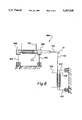
- FIG. 6 schematically shows one example of a motion generator as contemplated by one example of the invention.
- FIG. 7 shows schematically an alternate embodiment of the laser gyro of the invention.
- FIG. 8 shows schematically an alternate embodiment of a motion generator as contemplated by the invention.
- the laser apparatus 10A comprises a laser gyro path 12, a saturable absorber 214, a dye gain medium 216, first and second prisms 24, 32, first and second corner mirrors 50, 52, output coupler 34, output mirror 36, optical delay element 40, and detector 44.
- the gyroscopic response or scale factor R of a ring laser is the ratio of the beat note ⁇ (in Hz) between the counterpropagating modes in the laser, to the rotation rate ⁇ (in radian/s) of the laser support.
- ⁇ in Hz
- ⁇ in radian/s
- accurate delay lines have to be used to make the pulse trains corresponding to the two opposite senses of rotation interfere on the detector.
- a beat note between the two fs-pulse trains is readily understood in the frequency domain.
- Each pulse train corresponds to a comb of equally spaced spectral lines which are called laser modes.
- the spectral combs of the two pulse trains are identical but shifted with respect to each other by a small amount due, for example, to a cavity rotation.
- the beat note is a measure of the relative shift between the two spectral combs. If A is the ring laser area, P its perimeter and ⁇ the wavelength, the gyroscopic response is given by: ##EQU1
- the resulting cavity 10A shown in FIG. 2, has an area of 1.42 m 2 and a perimeter of 5.09 m.
- the scale factor R is 0.79915 MHz/(radian/s) or 31.40 kHz/(°/s) .
- FIG. 3 shows a plot 300 of the beat frequency on abscissa 302 versus the rotation rate on ordinate 304.
- the pulse duration is about 100 fs.
- the beat frequency is obtained by overlapping the two pulse trains temporally and spatially on a slow photodiode via an extracavity delay line 40, as shown in FIG. 2.
- the data confirm the absence of measurable dead band noted on measurement of Fresnel drag.
- the bias of the laser is attributed to the unbalance of the pulse energies at both the gain and absorber jets and the nonlinearities of the jets.
- the observations point to saturation induced changes in index in the absorber and gain jets. While the intensities are nearly balanced at the absorber jet (as expected because of the mutual coupling through the transient grating in the absorber), there can be as much as 20% imbalance between the two intensities at the gain jet.
- the strong saturation lensing at the absorber jet explains the strong dependence of the bias note on the jet position.
- the slope of the data corresponds substantially exactly to the predicted scale factor. No departure from linearity can be observed within the accuracy of the measurement.
- the error bars in the abscissa are due to inaccuracies of the drive mechanism at the lowest speeds.
- the waveform of the beat note is approximately sinusoidal down to the lowest frequencies observable. Even at the lowest frequencies, modulation in the amplitude of any of the beams is not observed. These two observations concur to indicate a very low threshold for lock-in.
- a scattering element namely an antireflection coated glass window was introduced at the pulse crossing point opposite to the absorber jet.
- the amount of coupling was adjusted by translating the glass scatterer through the crossing point, resulting in a conventional dead band in the gyro response.
- the width of the dead band is, as expected, of the order of the pulse length (i.e. 50 ⁇ m).
- such a value for the backscattering coefficient corresponds to a lock-in rotation rate of 5°/s for a ring of 1.4 m 2 area, at a wavelength of 620 nm.
- the actual lock-in rate should be much larger, in view of the additional contribution from the absorber dye.
- FIG. 4A is a trace showing no scatters.
- FIG. 4B shows scatters at rest.
- FIGS. 4C-4F are increasing magnitudes of motion. In trace 4F, the beat note resumed its shape as if there were no scatters.
- FIGS. 4A-4F can be readily understood by examining the equation of motion of the relative phase ⁇ between a pair of the beating modes ##EQU3## where ⁇ , ⁇ , and ⁇ are respectively the mode splitting (beat note frequency) due to cavity rotation or bias, the coupling coefficient of the modes, and the phase shift of the backscattering.
- ⁇ , ⁇ , and ⁇ are respectively the mode splitting (beat note frequency) due to cavity rotation or bias, the coupling coefficient of the modes, and the phase shift of the backscattering.
- the phase shift ⁇ changes much faster than ⁇ the second term in Equation (3) vanishes on average, and the two laser modes experience no coupling.
- the requirement for eliminating the dead band appears to be the scattering particles moving through the beam in a time much shorter than the period of the beat note to be observed. This is what happens in the dye laser.
- the transient time of the scatters in the absorber jet is about 1 ⁇ s, much shorter than the typical beat note period of 1 ms.
- a great advantage of a mode-locked laser gyro is the feasibility of introducing intracavity elements without disturbing its gyroscopic response, provided that the inserted elements are not located at the pulse crossing points.
- a passively mode-locked, all solid state ring laser gyro may be fabricated.
- the absorber section of the laser should be kept moving transversely to the laser beams in, for instance, a circular fashion.
- the investigated laser system is basically a very sensitive instrument for anisotropic measurement. Because of the feasibility of adding intracavity optics, the laser is suitable for many intracavity experiments which are not possible with CW ring lasers. In particular, when a sample is located away from the pulse crossing points, any index change induced by, for instance, an electrical or optical pulse train synchronized with one of the cavity pulse can be measured via the beat frequency. In addition, because the cavity pulse is of 100 fs, the above measurement can have a high time resolution. Also, intracavity pump-probe experiments can be straightforward. In these experiments, one of the cavity pulse is used as a pump pulse, and the other, as a probe pulse; the relative delay can be obtained simply by moving the sample away or toward a pulse crossing point.
- the apparatus comprises a laser gyro 10 including a laser gyro path 12, a solid state absorber 14, a solid state gain medium 16, first and second prisms 24, 32, first and second corner mirrors 50, 52, output coupler 34, output mirror 36, optical delay element 40, and detector 44.
- a motion generator 100 is coupled by coupling means 1102 to the solid state absorber 14.
- the solid state absorber 14 may advantageously comprise a multiple quantum well (MQW) semiconductor device as disclosed, for example, by Raja et al.
- MQW multiple quantum well
- the multiple quantum well semiconductor device is a saturable absorber.
- the gain medium 16 may advantageously comprise any well known gain medium.
- the prisms 24, 32 are optional and are employed in a well known manner for conditioning the beams.
- an external energy source (not shown) provides electrical or other type of appropriate energy E to stimulate the gain medium 16.
- the stimulation energy E in this example, is reflected into the gain medium 16 via focusing mirror 18 and the gain medium 16 lases along path 12.
- mirror 18 would not be needed in the case where electrical energy is employed to stimulate the gain medium. In that case an electrical connection would be used.
- Mirrors 20 and 22 may be employed advantageously to direct the laser emission from gain medium 16.
- the absorber 14 is located between mirrors 54 and 56 which focus the laser emission onto the absorber 14.
- the absorber 14 creates first and second counterpropagating pulses 28 and 46 respectively.
- the first pulse 28 propagates in a counter clockwise direction around the path 12 as indicated by arrow 26.
- pulses 46 and 28 comprise pulses each having a short pulse duration of about 100 femtoseconds.
- the pulses propagate around the laser path at a rate of one pulse every ten nanoseconds.
- the semiconductor absorber 14 is located such that the counterpropagating pulses periodically meet at the middle of the absorber medium 14.
- the motion generator 100 introduces a substantially circular motion onto the semiconductor absorber 14. Movement of the semiconductor absorber 14 may advantageously be done transversely to the motion of scatters. The induced vibration, therefore, effectively dithers the absorber, thereby substantially reducing or eliminating the dead band in the laser gyro.
- the lock-in phenomenon wherein the two laser modes couple together, is substantially eliminated.
- the motion generator 100 comprises first and second solenoid coils 102,104, first and second solenoid shafts 112,118, and first and second spring blades 114, 116.
- the first and second spring blades 114, 116 are coupled to the semiconductor absorber 14.
- the mechanism shown is to be understood to be by way of example and not by way of limitation.
- the first and second coils 102,104 may be, for example, voice coils as may be commonly employed in, for example, computer disk drives.
- the coils 102,104 together with the first and second shafts 112,118 operate as solenoids to move the shafts 112, 118 in transverse motions with respect to each other as indicated generally by directional arrows 106, 108.
- the shafts are coupled to the spring blades which are selected to be flexible enough so as to induce a circular motion of the semiconductor absorber 14, generally indicated by circular arrow 110.
- the coils When the coils are activated they cause transverse motion of the shafts which results in a generally circular motion of the absorber 14.
- the semiconductor absorber 14 may be advantageously cylindrically moved in such a way at a rate of about 50 Hz or more. Other frequencies may be employed depending upon the type of gyro, the size of the ring laser path and other variables.
- the mechanism in one embodiment of the invention may move the semiconductor absorber in a circular path having a diameter of about 1 mm.
- the laser path 12 represents any of a plurality of types of laser waveguides.
- the laser path 12 may advantageously comprise an optical path, a fiber waveguide, a solid state waveguide or other functionally equivalent laser waveguide.
- Laser gyro 710 includes a laser path 712, dispersive prisms 714,724,734 and 726. Also included are a gain element 16 and a semiconductor absorber 14 which are operated in a manner similarly to that described hereinabove with reference to FIG. 1. That is, the semiconductor absorber is located at a crossing point where the counterpropagating pulses periodically meet. A second crossing point exists at location 750 which is equidistant from absorber 14. The laser is generally centered on an axis 740 passing through the center of a mirror 732.
- Dashed arrow 728, 731 indicate counterpropagating pulsed outputs to a detector 730.
- the detector 730 may be any well known detector mechanism and may be similar to the detection device described hereinabove with reference to FIGS. 1 and 2.
- Double-ended arrow 70 indicates the movement of semiconductor absorber element 14 by a motion generator such as the one shown in FIG. 1.
- the dispersive prisms may comprise, for example, ZnSe material.
- the gain element 16 may comprise, for example, Gallium Arsenide (GaAs).
- a motion generator 800 includes coils 102 and 104, electromagnetic element shafts 112, 118 and first and second spring blades 114, 116.
- Electromagnetic shaft 112 is secured in housings 802 and 804 which are further connected to third and fourth spring blades 810.
- the third and fourth spring blades 810 are secured to a mechanical ground.
- the second electromagnetic shaft element 118 is attached at a first end to a fifth spring blade 810 and at a second end to a sixth spring blade 810.
- the fifth and sixth spring blades are also connected to a mechanical ground.
- Spring blade 114 is attached to shaft 112 at a first end and to the absorber element 14 at a second end.
- spring blade 116 is attached at a first end to the absorber element 14 and at a second end to the shaft 118. The transverse movement of the shafts in an oscillatory fashion will cause the absorber element 14 to rotate in a substantially circular motion.
Abstract
Description
Claims (16)
Priority Applications (1)
| Application Number | Priority Date | Filing Date | Title |
|---|---|---|---|
| US07/880,802 US5367528A (en) | 1992-05-08 | 1992-05-08 | Motion induced elimination of dead band in a short pulse laser gyro |
Applications Claiming Priority (1)
| Application Number | Priority Date | Filing Date | Title |
|---|---|---|---|
| US07/880,802 US5367528A (en) | 1992-05-08 | 1992-05-08 | Motion induced elimination of dead band in a short pulse laser gyro |
Publications (1)
| Publication Number | Publication Date |
|---|---|
| US5367528A true US5367528A (en) | 1994-11-22 |
Family
ID=25377130
Family Applications (1)
| Application Number | Title | Priority Date | Filing Date |
|---|---|---|---|
| US07/880,802 Expired - Fee Related US5367528A (en) | 1992-05-08 | 1992-05-08 | Motion induced elimination of dead band in a short pulse laser gyro |
Country Status (1)
| Country | Link |
|---|---|
| US (1) | US5367528A (en) |
Cited By (8)
| Publication number | Priority date | Publication date | Assignee | Title |
|---|---|---|---|---|
| US6546027B1 (en) | 1999-12-01 | 2003-04-08 | Hoya Photonics, Inc. | Laser saturable absorber and passive negative feedback elements, and method of producing energy output therefrom |
| US6650682B1 (en) | 1999-04-30 | 2003-11-18 | University Of New Mexico | Bi-directional short pulse ring laser |
| US6912053B1 (en) * | 2003-03-17 | 2005-06-28 | Sandia Corporation | Ring laser scatterometer |
| EP1890107A1 (en) * | 2006-08-18 | 2008-02-20 | Thales | Solid-state gyrolaser with mechanically activated gain medium |
| FR2937740A1 (en) * | 2008-10-28 | 2010-04-30 | Thales Sa | DEVICE AND METHOD FOR VIBRATION OF A SOLID AMPLIFIER ELEMENT WITHIN A GYROLASER |
| RU2562149C2 (en) * | 2013-04-10 | 2015-09-10 | Федеральное государственное автономное образовательное учреждение высшего профессионального образования "Южный федеральный университет" (Южный федеральный университет) | Resonant measuring method of rotation frequency of object and device implementing this method |
| US10317212B1 (en) | 2017-05-19 | 2019-06-11 | Stc.Unm | Enhancement of the phase response of intracavity phase interferometers |
| US11821838B1 (en) * | 2020-06-01 | 2023-11-21 | Jean-Claude Diels | Spectroscopy in frequency, time, and position with correlated frequency combs |
Citations (4)
| Publication number | Priority date | Publication date | Assignee | Title |
|---|---|---|---|---|
| US4525843A (en) * | 1982-04-29 | 1985-06-25 | The United States Of America As Represented By The Secretary Of The Navy | Ring laser with wavefront conjugating beams |
| US4815080A (en) * | 1986-05-14 | 1989-03-21 | Centre National De La Recherche Scientifique | Laser providing stable femtosecond pulses |
| US5017806A (en) * | 1990-04-11 | 1991-05-21 | Cornell Research Foundation, Inc. | Broadly tunable high repetition rate femtosecond optical parametric oscillator |
| US5119383A (en) * | 1990-12-28 | 1992-06-02 | The United States Of America As Represented By The Secretary Of The Navy | Antiresonant nonlinear mirror for passive laser modelocking |
-
1992
- 1992-05-08 US US07/880,802 patent/US5367528A/en not_active Expired - Fee Related
Patent Citations (4)
| Publication number | Priority date | Publication date | Assignee | Title |
|---|---|---|---|---|
| US4525843A (en) * | 1982-04-29 | 1985-06-25 | The United States Of America As Represented By The Secretary Of The Navy | Ring laser with wavefront conjugating beams |
| US4815080A (en) * | 1986-05-14 | 1989-03-21 | Centre National De La Recherche Scientifique | Laser providing stable femtosecond pulses |
| US5017806A (en) * | 1990-04-11 | 1991-05-21 | Cornell Research Foundation, Inc. | Broadly tunable high repetition rate femtosecond optical parametric oscillator |
| US5119383A (en) * | 1990-12-28 | 1992-06-02 | The United States Of America As Represented By The Secretary Of The Navy | Antiresonant nonlinear mirror for passive laser modelocking |
Non-Patent Citations (9)
| Title |
|---|
| Christian, et al., Picosecond Pulsed Diode Ring Laser Gyroscope, Optical Society of America, 1991. * |
| Christian, et al., Picosecond Pulsed Diode Ring-Laser Gyroscope, Optical Society of America, 1991. |
| Delfyett, et al., Generation of Subpicosecond High Power Optical Pulses from a Hybrid Mode Locked Semiconductor Laser, Optics Letters, Dec. 1, 1990, vol. 15, No. 23. * |
| Delfyett, et al., Generation of Subpicosecond High-Power Optical Pulses from a Hybrid Mode-Locked Semiconductor Laser, Optics Letters, Dec. 1, 1990, vol. 15, No. 23. |
| Diels, et al., Degenerate Four Wave Mixing of Femtosecond Pulses in an Absorbing Dye Jet, Journal of Optical Society of America B, vol. 3, p. 535, Apr. 1986. * |
| Diels, et al., Degenerate Four-Wave Mixing of Femtosecond Pulses in an Absorbing Dye Jet, Journal of Optical Society of America B, vol. 3, p. 535, Apr. 1986. |
| Lai, et al., Interference Between Spontaneous Emission in Different Directions, 29 Jan. 1990, Am. J. Phys. 58(10) Oct. 1990. * |
| Raja, et al., Novel Wavelength Resonant Optoelectronic Structure and its Application to Surface Emitting Semiconductor Lasers, Electronics Letters, 1 Sep. 1988, vol. 24, No. 18. * |
| Salin, et al., Nonreciprocal Phase Shifts in a Femtosecond Dye Laser, Optics Letters, vol. 5, No. 16, Aug. 1990. * |
Cited By (15)
| Publication number | Priority date | Publication date | Assignee | Title |
|---|---|---|---|---|
| US6650682B1 (en) | 1999-04-30 | 2003-11-18 | University Of New Mexico | Bi-directional short pulse ring laser |
| US6546027B1 (en) | 1999-12-01 | 2003-04-08 | Hoya Photonics, Inc. | Laser saturable absorber and passive negative feedback elements, and method of producing energy output therefrom |
| US6912053B1 (en) * | 2003-03-17 | 2005-06-28 | Sandia Corporation | Ring laser scatterometer |
| US7589841B2 (en) | 2006-08-18 | 2009-09-15 | Thales | Solid-state laser gyro with a mechanically activated gain medium |
| US20080043225A1 (en) * | 2006-08-18 | 2008-02-21 | Thales | Solid-state laser gyro with a mechanically activated gain medium |
| FR2905005A1 (en) * | 2006-08-18 | 2008-02-22 | Thales Sa | SOLID STATE GYROLASER WITH MECHANICALLY ACTIVE GAIN MEDIUM. |
| EP1890107A1 (en) * | 2006-08-18 | 2008-02-20 | Thales | Solid-state gyrolaser with mechanically activated gain medium |
| CN101126643B (en) * | 2006-08-18 | 2011-10-26 | 泰勒斯公司 | Solid-state laser gyro with a mechanically activated gain medium |
| FR2937740A1 (en) * | 2008-10-28 | 2010-04-30 | Thales Sa | DEVICE AND METHOD FOR VIBRATION OF A SOLID AMPLIFIER ELEMENT WITHIN A GYROLASER |
| WO2010049374A1 (en) * | 2008-10-28 | 2010-05-06 | Thales | Device and method for vibrating a solid amplification member within a gyrolaser |
| US20110205546A1 (en) * | 2008-10-28 | 2011-08-25 | Thales | Device and Method for Vibrating a Solid Amplification Member Within a Gyrolaser |
| US8619262B2 (en) | 2008-10-28 | 2013-12-31 | Thales | Device and method for vibrating a solid amplification member within a gyrolaser |
| RU2562149C2 (en) * | 2013-04-10 | 2015-09-10 | Федеральное государственное автономное образовательное учреждение высшего профессионального образования "Южный федеральный университет" (Южный федеральный университет) | Resonant measuring method of rotation frequency of object and device implementing this method |
| US10317212B1 (en) | 2017-05-19 | 2019-06-11 | Stc.Unm | Enhancement of the phase response of intracavity phase interferometers |
| US11821838B1 (en) * | 2020-06-01 | 2023-11-21 | Jean-Claude Diels | Spectroscopy in frequency, time, and position with correlated frequency combs |
Similar Documents
| Publication | Publication Date | Title |
|---|---|---|
| US6038055A (en) | Method and device for generating phase-coherent light pulses | |
| JP2554614B2 (en) | Laser device with output stabilizing external passive cavity | |
| US8208505B2 (en) | Laser system employing harmonic generation | |
| Bjorkholm | Optical second-harmonic generation using a focused Gaussian laser beam | |
| US4396290A (en) | Two pump-frequency-stimulated Brillouin scattering ring laser gyroscope | |
| US20130215925A1 (en) | Method of generating enhanced intra-resonator laser light, enhancement resonator and laser device | |
| US6650682B1 (en) | Bi-directional short pulse ring laser | |
| US5367528A (en) | Motion induced elimination of dead band in a short pulse laser gyro | |
| US4048515A (en) | Broadband laser with intracavity crystal for generating second harmonic radiation | |
| US20200088878A1 (en) | Lidar system with integrated frequency shifter for true doppler detection | |
| Arnold et al. | Efficient generation of surface acoustic waves by thermoelasticity | |
| Scott et al. | High-efficiency scattering in transient Brillouin-enhanced four-wave mixing | |
| US5251230A (en) | Resonant cavity dither with index of refraction modulator | |
| RU2381450C2 (en) | Laser gyroscope with solid-state semiconductor medium with vertical structure | |
| EP0492994B1 (en) | Mode-locked laser using non-linear self-focusing element | |
| EP0467939B1 (en) | Ring laser | |
| US4178079A (en) | Sub-picosecond optical gating by degenerate four-wave mixing | |
| US5500729A (en) | Magneto-optical arrangement for laser radar | |
| Gnass et al. | Sagnac effect in the colliding-pulse-mode-locked dye ring laser | |
| Koeppel et al. | High-Precision Localization of Trapped Microparticles inside Hollow-Core Photonic Crystal Fibers using Coherent Optical Frequency Domain Reflectometry | |
| Miles et al. | A high-power CO 2 laser radar transmitter | |
| Balakshy et al. | Laserlike acousto-optic generator | |
| King | Lasers and their application to navigation | |
| Islam et al. | Generation of a guided mode in a THz semiconductor waveguide using excitation by a tilted optical pulse front | |
| Diels et al. | Accurate Range Gating Technique with Mode-Locked Dye Lasers |
Legal Events
| Date | Code | Title | Description |
|---|---|---|---|
| AS | Assignment |
Owner name: HONEYWELL INC. A CORP. OF DELAWARE, MINNESOTA Free format text: ASSIGNMENT OF ASSIGNORS INTEREST.;ASSIGNOR:LAI, MING;REEL/FRAME:006176/0538 Effective date: 19920618 Owner name: HONEYWELL INC. A CORP. OF DELAWARE, MINNESOTA Free format text: ASSIGNMENT OF ASSIGNORS INTEREST.;ASSIGNOR:DIELS, JEAN-CLAUDE M.;REEL/FRAME:006176/0534 Effective date: 19920618 |
|
| FEPP | Fee payment procedure |
Free format text: PAYOR NUMBER ASSIGNED (ORIGINAL EVENT CODE: ASPN); ENTITY STATUS OF PATENT OWNER: LARGE ENTITY |
|
| FPAY | Fee payment |
Year of fee payment: 4 |
|
| AS | Assignment |
Owner name: NEW MEXICO, UNIVERSITY OF, NEW MEXICO Free format text: ASSIGNMENT OF ASSIGNORS INTEREST;ASSIGNOR:HONEYWELL, INC.;REEL/FRAME:011204/0936 Effective date: 19961002 |
|
| FPAY | Fee payment |
Year of fee payment: 8 |
|
| AS | Assignment |
Owner name: HONEYWELL INTERNATIONAL INC., NEW JERSEY Free format text: ASSIGNMENT OF ASSIGNORS INTEREST;ASSIGNOR:NEW MEXICO, UNIVERSITY OF;REEL/FRAME:012906/0257 Effective date: 20020423 |
|
| REMI | Maintenance fee reminder mailed | ||
| LAPS | Lapse for failure to pay maintenance fees | ||
| STCH | Information on status: patent discontinuation |
Free format text: PATENT EXPIRED DUE TO NONPAYMENT OF MAINTENANCE FEES UNDER 37 CFR 1.362 |
|
| FP | Lapsed due to failure to pay maintenance fee |
Effective date: 20061122 |