US5371895A - Local equipment controller for computerized process control applications utilizing language structure templates in a hierarchical organization and method of operating the same - Google Patents
Local equipment controller for computerized process control applications utilizing language structure templates in a hierarchical organization and method of operating the same Download PDFInfo
- Publication number
- US5371895A US5371895A US07/769,116 US76911691A US5371895A US 5371895 A US5371895 A US 5371895A US 76911691 A US76911691 A US 76911691A US 5371895 A US5371895 A US 5371895A
- Authority
- US
- United States
- Prior art keywords
- control
- statements
- language
- language structure
- loop
- Prior art date
- Legal status (The legal status is an assumption and is not a legal conclusion. Google has not performed a legal analysis and makes no representation as to the accuracy of the status listed.)
- Expired - Fee Related
Links
Images


Classifications
-
- G—PHYSICS
- G05—CONTROLLING; REGULATING
- G05B—CONTROL OR REGULATING SYSTEMS IN GENERAL; FUNCTIONAL ELEMENTS OF SUCH SYSTEMS; MONITORING OR TESTING ARRANGEMENTS FOR SUCH SYSTEMS OR ELEMENTS
- G05B19/00—Programme-control systems
- G05B19/02—Programme-control systems electric
- G05B19/04—Programme control other than numerical control, i.e. in sequence controllers or logic controllers
- G05B19/042—Programme control other than numerical control, i.e. in sequence controllers or logic controllers using digital processors
- G05B19/0426—Programming the control sequence
-
- G—PHYSICS
- G05—CONTROLLING; REGULATING
- G05B—CONTROL OR REGULATING SYSTEMS IN GENERAL; FUNCTIONAL ELEMENTS OF SUCH SYSTEMS; MONITORING OR TESTING ARRANGEMENTS FOR SUCH SYSTEMS OR ELEMENTS
- G05B2219/00—Program-control systems
- G05B2219/20—Pc systems
- G05B2219/23—Pc programming
- G05B2219/23258—GUI graphical user interface, icon, function bloc editor, labview
-
- G—PHYSICS
- G05—CONTROLLING; REGULATING
- G05B—CONTROL OR REGULATING SYSTEMS IN GENERAL; FUNCTIONAL ELEMENTS OF SUCH SYSTEMS; MONITORING OR TESTING ARRANGEMENTS FOR SUCH SYSTEMS OR ELEMENTS
- G05B2219/00—Program-control systems
- G05B2219/20—Pc systems
- G05B2219/23—Pc programming
- G05B2219/23261—Use control template library
-
- G—PHYSICS
- G05—CONTROLLING; REGULATING
- G05B—CONTROL OR REGULATING SYSTEMS IN GENERAL; FUNCTIONAL ELEMENTS OF SUCH SYSTEMS; MONITORING OR TESTING ARRANGEMENTS FOR SUCH SYSTEMS OR ELEMENTS
- G05B2219/00—Program-control systems
- G05B2219/20—Pc systems
- G05B2219/23—Pc programming
- G05B2219/23266—Compiler
-
- G—PHYSICS
- G05—CONTROLLING; REGULATING
- G05B—CONTROL OR REGULATING SYSTEMS IN GENERAL; FUNCTIONAL ELEMENTS OF SUCH SYSTEMS; MONITORING OR TESTING ARRANGEMENTS FOR SUCH SYSTEMS OR ELEMENTS
- G05B2219/00—Program-control systems
- G05B2219/20—Pc systems
- G05B2219/23—Pc programming
- G05B2219/23274—Link graphical data for display automatically into program
-
- Y—GENERAL TAGGING OF NEW TECHNOLOGICAL DEVELOPMENTS; GENERAL TAGGING OF CROSS-SECTIONAL TECHNOLOGIES SPANNING OVER SEVERAL SECTIONS OF THE IPC; TECHNICAL SUBJECTS COVERED BY FORMER USPC CROSS-REFERENCE ART COLLECTIONS [XRACs] AND DIGESTS
- Y10—TECHNICAL SUBJECTS COVERED BY FORMER USPC
- Y10S—TECHNICAL SUBJECTS COVERED BY FORMER USPC CROSS-REFERENCE ART COLLECTIONS [XRACs] AND DIGESTS
- Y10S715/00—Data processing: presentation processing of document, operator interface processing, and screen saver display processing
- Y10S715/961—Operator interface with visual structure or function dictated by intended use
- Y10S715/965—Operator interface with visual structure or function dictated by intended use for process control and configuration
Definitions
- the present invention relates generally to the field of computer-controlled process equipment controllers, as well as to the field of control systems. More particularly, the present invention relates to an apparatus and method (i.e., an applications-oriented computer language structure and translator therefor, such as an interpreter or compiler) for developing, describing, and implementing process control of a single process device which participates in batch or continuous industrial process control.
- the local equipment controller and program for operating the same is generally used in a stand alone configuration wherein the controller directly controls a single vessel processing unit.
- the method of operating the local equipment controller accommodates the writing of programs in terms of self-documenting statements of control objectives or intentions.
- the present invention has broad application in a wide range of computer-driven control applications and analogous environments. Its virtues and operation will best be understood if it is described in the context of a specific type of control system, rather than in the abstract. For convenience, the context for explanatory purposes will be the field of industrial process control; it should be appreciated, however, that this is simply an exemplary context and is not limiting of the invention.
- Industrial process control refers to the control of manufacturing processes in industries wherein a product is, in at least some significant stage of production, a homogeneous fluid capable of being flowed in pipes or a stream of particles capable of being moved by a conveyor belt.
- the product can be operated upon by simple actuators such as valves, baffles and deflectors and its state can be determined (or at least estimated) by simple probing and sampling sensors.
- simple actuators such as valves, baffles and deflectors
- Typical industries included within this framework are those which manufacture petroleum products, chemicals, power, paper, films, metals, textiles, plastics, foods, drugs, cement, and, increasingly, semiconductors.
- single vessel processing unit refers to a single processing station, which may be free standing, for accomplishing a particular predetermined processing task or series of tasks.
- the single vessel processing unit may receive material input from a previous single vessel processing unit and may send its output onto another single vessel processing unit.
- Large process control systems may be built up from a number of single vessel processing units.
- An example of a single vessel processing unit might be a retort or a dyebeck.
- a processing complex typically may be organized into a hierarchy of (from bottom to top) units, processes, and plants. At the lowest levels, the elements may be integrated in an appropriate manner governed by the requirement of meeting the detailed stoichiometric requirements involved in producing a given product. At higher levels, processing may be more flexibly arranged and rearranged to respond to the needs of the business (e.g., to take advantage of the processing units which happen to be available at the time there is a desire to manufacture a given product).
- the present invention addresses the lower levels, where there is a desire for a highly integrated automation of control processing; it is well-suited to batch control and continuous control systems which use single vessel processing units.
- the scheduling and rearrangement of the higher level processing resources is the role of process management, not process control, and is therefore outside the scope of this invention.
- the sequencing of the production procedure is divided hierarchically into various levels of operation.
- the divisions are made generally along the lines of stages of production, operator intervention and monitoring. This facilitates the use of a plant for producing a variety of products.
- the physical plant resources may be shared so that these products may be produced at different times while using some or all of the same production equipment, either by rearranging the processing or by using the same procedure but varying parameters to yield a different grade of product.
- Control automation in this environment must provide a method for imposing control procedures in a relatively simple form.
- control automation process automate the record-keeping associated with the production of each lot, based on the control parameterization and sources of raw materials used therefor; this is important since there is often a need or desire, at some later time, to be able to identify the source of particular characteristics in a product.
- record keeping system should have the capability of displaying the recorded data in a variety of different formats, such as bar graphs and line graphs so that trends in process variables or product characteristics can be identified and corrected, if necessary.
- a given industrial process may have to be adjusted or changed from time to time--for example, to accommodate a substitution of raw materials or to make an improvement to the product. It is therefore important that the users of a computer-controlled single vessel processing unit be able to identify the portions (and the specific instructions) of the control program which require revision. In the past, these requirements have given rise to a frequently-unfulfilled need for extensive documenting of such programs, parameters, and materials. This level of documentation is only achieved at considerable expense. And undocumented changes could be difficult to detect and analyze.
- this language structure exhibits the following characteristics: (1) it organizes the control system into logically distinct application subsystems according to processing and control activities; (2) it provides distinct representations for logically different control activities; (3) it orders the display of configured data to make it predictable and easy to read and understand; (4) it represents and displays the program structure graphically, in a way which guides the eye to and through critical relationships; (5) it employs command statements which define precise application function roles, to reduce ambiguity in the underlying intent and in the relationship between the functional elements of a control program; and (6) it uses logical and/or standard application functions and practices to account for implied configuration activities.
- an object of the present invention is to provide a local equipment controller and method for operating the same, which method includes a subset or simplified instruction set of the computer language described in the '320 patent.
- Another object of the present invention is to provide a computer language structure and local equipment controller using the same wherein the language structure allows a control system designer to program in terms of the control functions he desires to implement, rather than in terms of the computer's internal details.
- Another object of the present invention is to provide a computer language structure for use in developing programs to control local equipment controllers, such that the control programs are largely self-documenting.
- Another object of the present invention is to provide a computer language structure in which the temporal relationships between controlled processes are readily apparent to a reader of a program listing.
- Another object of the present invention is to provide a data structure for a programming environment in which supporting details for carrying out control operations are segregated from expressions of control intentions, so as to enhance representation of the control intentions.
- Another object of the present invention is to provide a data structure that provides for reduced processing overhead during execution, and provides for certainty and simplicity of execution.
- Another object of the present invention is to provide a local equipment controller having a predefined set of control solutions for controlling a variety of processes supplied therewith.
- Another object of the present invention is to provide a programming format that is fixed so that control intentions and understanding of program control is enhanced.
- Another object of the present invention is to provide a user interface in a local equipment controller which user interface provides an operator user interface and a programming user interface wherein the user interface makes use of graphic features which have command significance.
- a computer-controlled equipment controller for controlling industrial process control equipment which uses a language structure and translator specifically adapted for use in constructing computer programs for controlling chemical and physical processing.
- the novel method of operating and programming the computer includes language structures which reflect the control engineer's objectives in an idiomatic fashion.
- the database upon which the language structure of the present invention operates is implemented as a single, contiguous memory segment which is scanned during each sample time to provide for regularity of program execution in combination with reduced processing overhead.
- the language structure of the invention is based on a three-level hierarchy of control function with sequencing and coordination at the highest level, continuous loop control at the middle level, and process I/O point operation at the lowest level.
- the language structure of the present invention is designed to reflect a simple structured approach based on fairly standardized higher level sequenced or coordinated control of lower level continuous controls. The consistency of such a structure allows a simpler program and equally structured operating displays.
- FIG. 1 illustrates one example of a hardware embodiment of the present invention
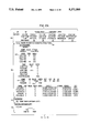
- FIGS. 2A, 2B, 2C and 2D illustrates an exemplary program listing which may be written by a control engineer using the language structure of the present invention to operate the hardware embodiment illustrated in FIG. 1;
- FIG. 3 illustrates an example of a FOOTNOTE language structure of the present invention
- FIG. 4 illustrates a truth table language structure of the present invention
- FIG. 5 illustrates a general form of a LOOP STATEMENT EXPRESSION language structure of the present invention which includes a controlled VARIABLE, an IDIOM, and a manipulated VARIABLE
- FIG. 6 illustrates exemplary IDIOM icons which form building blocks used in the iconic form of the LOOP STATEMENT EXPRESSION illustrated in FIG. 5;
- FIG. 7 illustrates the general form of an inline LOOP STATEMENT EXPRESSION language structure
- FIG. 8 illustrates the cascading of inline LOOP STATEMENT EXPRESSIONS illustrated in FIG. 7 to form a LOOP STATEMENT language structure
- FIG. 9 illustrates the general form of a supporting LOOP STATEMENT EXPRESSION language structure as it modifies an inline LOOP STATEMENT EXPRESSION;
- FIG. 10 illustrates a feedforward example of the supporting LOOP STATEMENT language structure
- FIG. 11 illustrates the general form of an override LOOP STATEMENT EXPRESSION language structure as it modifies an inline LOOP STATEMENT EXPRESSION;
- FIG, 12 illustrates an example of the override LOOP STATEMENT language structure
- FIG. 13 illustrates the general form of a bypass LOOP STATEMENT EXPRESSION language structure as it modifies an inline LOOP STATEMENT EXPRESSION;
- FIG. 14 illustrates an example of the bypass LOOP STATEMENT language structure
- FIG. 15 illustrates the general form of a fanout LOOP STATEMENT EXPRESSION language structure as it modifies an inline LOOP STATEMENT EXPRESSION;
- FIG. 16 illustrates an example of the fanout LOOP STATEMENT language structure
- FIG. 17 illustrates an example of a blend THEME STATEMENT language structure
- FIG. 18 illustrates an example of a ramp THEME STATEMENT language structure
- FIG. 19 illustrates an example of sequencer THEME STATEMENT language structure
- FIG. 20 illustrates an example of a timer THEME STATEMENT language structure
- FIG. 21 illustrates an example of stream THEME STATEMENT language structure
- FIG. 22 illustrates the data structure of a SUPERVARIABLE database used to support the language structures of the present invention
- FIG. 23 illustrates a memory management scheme used in the present invention
- FIG. 24 illustrates the overall program system organization of the present invention including a flow chart showing repetitive processing loops
- FIG. 25 includes flow charts illustrating the concept of scan loops used in the system organization illustrated in FIG. 23;
- FIG. 26 includes flow charts illustrating the concept of human user interface loops used in the interrupt loops illustrated in the system organization of FIG. 23;
- FIG. 27 illustrates a compiled version of the SUPERVARIABLE database illustrated in FIG. 22;
- FIG. 28 illustrates the overall concept of a SUPERVARIABLE program scan and buffering required to implement the program scan
- FIG. 29 includes a flow chart illustrating in more detail the SUPERVARIABLE program scan of FIG. 28;
- FIG. 30 illustrates an example of display data gathering, buffering, and display of data stored in the SUPERVARIABLE format illustrated in FIGS. 22, 28, and 29;
- FIG. 31 illustrates a LOOP STATEMENT to be processed for display by the methods illustrated in FIG. 30.
- FIG. 32 illustrates an exemplary trend display of the LOOP STATEMENT of FIG. 31 which may be generated using the processing illustrated in FIGS. 23-30.
- object is meant to describe a structure which includes the definitions of the object and the operations which may be carried out with that object (i.e., an object is a collection of data and methods).
- the present invention includes a computer-controlled process controller designed to control a single vessel processing unit.
- the present invention is contemplated as being directly connected to and controlling a particular single vessel processing unit.
- the process controller of the present invention for most applications, will be locally configured for control of the single vessel processing unit to which it is attached (i.e., a "local" equipment process controller).
- a local equipment process controller i.e., a "local" equipment process controller.
- the present invention is not so limited. With suitable communications hardware and software, multiple local equipment controllers of the present invention may be connected together in order to form a larger process control system.
- the multiple local equipment controllers may be controlled by a single central process controller which maintains systemwide control and management of an overall production system.
- the present invention will be explained using a single local equipment controller controlling a single vessel processing unit.
- the local equipment controller 10 includes a computer system unit 12 having at least a central processing unit and associated memory along with any required input/output devices, mass storage devices, and so on.
- the system unit 12 may be a general purpose computer capable of being programmed according to the method of the present invention.
- the system unit 12 may also include suitable communications hardware and software to enable multiple process controllers to be connected together via communications port 13 to form a larger process control system.
- the system unit 12 is connected by a suitable process I/O hardware and software represented by block 14 to the single vessel processing unit 16 which may be, for example, a dyebeck or a retort.
- the local equipment controller of the present invention additionally includes a display device 22 which may be any suitable display device such as a CRT, liquid crystal display, and so on which receives display data and/or commands over communications link 23.
- the method of the present invention involves a method of operating a computer which method is a further refinement of the computer language structure described in the '320 patent.
- a novel language structure and supporting data structure is utilized to provide for regularity of program execution in combination with reduced processing overhead.
- a menu-organized user interface may be provided to guide the control engineer and the system operator through the steps required to configure or run the local equipment controller.
- the computer language of the present invention is described in its most general form in the '320 patent.
- the language described in the '320 patent may be termed an "Idiomatic Control Language".
- the language is referred to as "idiomatic” because the language itself is designed to reflect the control system designer's intentions in an idiomatic fashion.
- the present invention is a subset or simplification (meaning a simplified instruction set) of the more general language and may be referred to as the "Idiomatic Control Language Subset".
- the Idiomatic Control Language Subset is based on a three level hierarchy of control function with sequencing and coordination at the highest level, continuous loop control (as normally implemented in terms of regulatory, feedback control, block diagrams, and their digital function block representation equivalents) at the middle level, and process I/O point operation at the lowest level.
- continuous loop control as normally implemented in terms of regulatory, feedback control, block diagrams, and their digital function block representation equivalents
- process I/O point operation at the lowest level.
- the term language structure is meant to refer to general elements of a language subject to their own formal syntax definition specifying a particular class of command sequence. These basic language structures are SUPERVARIABLEs, LOOP STATEMENTs, THEME STATEMENTs, PROCEDUREs, and FOOTNOTEs.
- a SUPERVARIABLE is both a language structure and an implementation device (in the form of a data structure).
- a SUPERVARIABLE provides the lowest level of control function in the hierarchy.
- a SUPERVARIABLE represents a variable supported with an arbitrary list of associated attributes, and includes the ability to represent several distinct variables in a single data structure (e.g., to concatenate variables).
- the attributes are specified in a format which defines the sequence of types of the attributes.
- the SUPERVARIABLE takes the form of a free form list of attributes, defined by the control engineer.
- the data structure supporting the SUPERVARIABLE forms the basic implementation vehicle for the local equipment controller computer program.
- a single SUPERVARIABLE structure is constructed wherein the entire program is translated into a string of type codes each with associated data.
- a process variable is defined as a segment of the SUPERVARIABLE which starts with one or more consecutive variable name attributes and includes no other internal variable name attributes.
- a LOOP STATEMENT occupies the middle level in the language hierarchy.
- a LOOP STATEMENT implements control of a single, measured, process VARIABLE (the "controlled” VARIABLE) through manipulation of one or more manipulated or actuator variables (the “manipulated” VARIABLEs).
- a LOOP STATEMENT may also include feed forward and constraint functions applied to other related measurements for associating a detailed computation with the higher level language structures.
- the LOOP STATEMENT replaces the computationally oriented function block of conventional practice, expressing control intentions and loop level integration. Specifically, the LOOP STATEMENT replaces the IDIOM SPACE of the '320 patent to provide a more simply structured approach for controlling a single vessel processing unit.
- a THEME STATEMENT occupies the highest level in the language hierarchy.
- a THEME STATEMENT is the highest level of operationally visible sequenced or coordinated control, which describes a predefined control solution for a typical control problem, such as commonly encountered batch, sequence, or continuous control problems.
- THEME STATEMENTs are based on pre-defined templates for a particular type of control task. Specific THEME STATEMENT formats may be provided which address specific control requirements.
- THEME STATEMENTs allow automation of part of the control system required for batch and/or continuous control.
- PROCEDUREs are bracketed sequences of general computational statements and other elements, treated as a unit, which describe less well structured activities needed to support the operation of the single vessel processing unit.
- a PROCEDURE is a catch-all computing function which may be used to control coordinating aspects of the single vessel processing unit which are not directly supported by any of the lower level, more formal language structures or operationally linked to displays, such as recipe set up and operational control of the background conditions of program execution.
- a FOOTNOTE is a device which allows arbitrary, detailed calculations to be associated with other language elements.
- FOOTNOTEs are used specifically in two ways in the present invention, although clearly, the FOOTNOTE as a structure is not so limited.
- a FOOTNOTE is a language structure used to associate a detailed computation with some higher level language element.
- FOOTNOTEs may be used to associate detailed calculations with attributes of the SUPERVARIABLE and THEME STATEMENTs.
- the FOOTNOTE provides a mechanism for defining arbitrary, detailed, computational refinements within a more systematic higher level language structure.
- the FOOTNOTE is also the implementation device for expressing and implementing all computations within the SUPERVARIABLE structure.
- the present invention comprehends a computer programming language, but it is also an application system and environment. It includes, as a language, all aspects of the control application programming and configuration, and all aspects of the operation from the configured controls.
- the present invention integrates control language and operation.
- the operational displays are derived from and integrated with the configured controls. Operational displays are therefore part of the computer language and the appearance and organization of the displays has command significance.
- FIG. 2 figure illustrates an exemplary application program listing of the present invention which is brought up on display 22 by an appropriate selection of keystrokes or menu choices.
- the format of the application listing has control significance as well as presenting the control system program to the control system engineer in a manner that reflects the control engineer's intentions and allows operation of the system to be readily visualized from the control program listing.
- FIG. 2 there is shown an application program listing of a control program that may be used to control a canning retort.
- the program listing is divided into paragraphs which assist the control engineer in visualizing program operation.
- the system automatically formats and orders the paragraphs as will be explained in greater detail.
- An appropriate sequence of keystrokes or menu selections is provided to allow the control engineer to enter and edit the data in the program.
- a first paragraph 30 contains the APPLICATION HEADING.
- the APPLICATION HEADING is generated by the system and repeated at the top of each listing continuation page (or each display screen) and lists the system and VARIABLE names. Repetition assists the control engineer with remembering VARIABLE names and system STATEs.
- the system name is RETORT, shown at 32.
- Columns 34, 36, 38, 40, 42, and 44 contain VARIABLE names assigned by the user.
- the user also assigns the system STATEs 46. STATEs are used to control and coordinate execution of state-dependent portions of the application program.
- the "/" between system STATEs indicates that the particular STATEs are mutually exclusive within a particular group of substates and the ",” separates each group of substates making up the STATE.
- certain STATEs are derived from the THEME STATEMENTs and there are basic built-in system states that provide fall-back control over the whole system, particularly in case of application program failure.
- the next paragraph of the program listing includes the VARIABLE DEFINITIONs paragraph 50.
- the VARIABLE DEFINITIONs paragraph of the program listing includes VARIABLEs having user defined names and attributes.
- FOOTNOTEs as a language structure, incorporate the specific required general calculations to be performed in support of control of a particular VARIABLE.
- the next paragraph of the program listing is the LOOP STATEMENTs paragraph, 80.
- the LOOP STATEMENTs paragraph provides a listing OF THE LOOP STATEMENTs in the program, such as the Heat/Cook LOOP STATEMENT 82 and the Cool LOOP STATEMENT 84 with their tuning parameters.
- THEME STATEMENTs paragraph 90 The next paragraph of the program listing is the THEME STATEMENTs paragraph 90. As illustrated at portion 92 in FIG. 2, THEME STATEMENTs may include their own FOOTNOTEs describing detailed calculations and assignments necessary to effect control.
- PROCEDUREs paragraph 100 The next paragraph of the program listing is the PROCEDUREs paragraph 100.
- PROCEDUREs describe all of the residual functions necessary to run a particular operation. The operation of PROCEDUREs is explained in more detail in the '320 patent, and the present invention makes use of PROCEDUREs in the same manner.
- the program listing is expressed in the reverse order of the hierarchy of the program objects.
- the basic process data and calculations are defined first in the VARIABLE DEFINITIONs and FOOTNOTEs paragraphs, respectively. Using that data, the control loops are defined onto that data in the LOOP STATEMENTs paragraph.
- the THEME STATEMENTs are defined after the LOOP STATEMENTs in the THEME STATEMENTs paragraph.
- any PROCEDUREs are defined in the PROCEDUREs paragraph to carry out any indirect overall coordination needed among the program paragraphs that have been previously defined.
- the standard organization of the program listing provides an immediate visual indication to the control engineer of the function and operation of the control program.
- the statements used in the program because of their idiomatic nature, immediately convey their functions to the engineer.
- the organization of the program itself in a reverse hierarchy helps the control engineer to visualize the system operation without requiring extensive additional documentation.
- the VARIABLE DEFINITIONs paragraph 50 corresponds to the DEFINITIONS PAGE in the '320 system.
- a VARIABLE is defined by supplying a name and a list of attributes through an appropriate combination of keystrokes or menu selections.
- a particular VARIABLE may have multiple attributes.
- the VARIABLE temp (at 52 in FIG. 2) in DEFINITIONs paragraph 50 has a number of attributes including in, value, units, set, deviation, and high and low values.
- the system automatically groups VARIABLEs having the same types of attributes together. For example, VARIABLEs venttime, heattime, cooktime and cooltime are grouped together as are VARIABLEs starttemp, prodtemp, cooktemp, bulbtemp and finaltemp.
- each attribute has a type name and a configuration related value.
- An attribute may also have STATEs derived from its operation or supporting its control. For example, a high alarm attribute has a real value associated with an alarm limit and an alarm state.
- the attributes are grouped in the listing into VARIABLE definitions, which are considered to include an initial name attribute, and all following attributes up to the next separated name attribute.
- the VARIABLE definitions are displayed as a row of values under a corresponding row of the corresponding attribute names, as shown in the FIG. 2 listing.
- the system automatically recognizes similarly arranged VARIABLEs when they occur consecutively, and arranges them under a single row of attribute type name headings as for example the VARIABLEs venttime, heattime, cooktime and cooltime shown in listing paragraph 50.
- VARIABLEs are processed in the order in which they have been defined in the VARIABLE DEFINITIONs paragraph. Therefore, the control engineer can control the order of system execution by the order in which VARIABLEs are defined.
- a FOOTNOTE is a language structure that allows coordination of low level, detailed activities with the state of execution of larger more fundamental program elements.
- FOOTNOTEs may be used to associate and coordinate low level, detailed activities, with any other higher level language structures.
- FOOTNOTEs may be placed anywhere in the system.
- FOOTNOTEs are executable code and calculations.
- FOOTNOTEs incorporate the details without complicating an otherwise simple program structure.
- FOOTNOTEs differ from ordinary subroutines because they are only called from one program location and do not have a name.
- FOOTNOTE may be used to associate the basic calculations with a VARIABLE (attribute) to allow some arbitrary compensation or modification of that VARIABLE.
- FOOTNOTEs may also be used to coordinate unstructured calculations with those THEME STATEMENTs whose functional focus is control of real process variables.
- FOOTNOTEs are shown in FIG. 3.
- an asterisk shown at 1014 can be placed at the end of a statement or definition entry such as the max attribute of the VARIABLE T100AV. Through appropriate key strokes, a number will automatically be assigned to the asterisk and to a separate location in both memory and on the display (at 106), where a detailed statement may be spelled out.
- Multiple FOOTNOTEs may be assigned to each attribute of a given variable. In the case illustrated in FIG. 3, the FOOTNOTE calculates the value of the VARIABLE T100AV as the sum of the values of variables T100, T101, T102 which sum is then divided by 3.
- FIG. 2 illustrates two FOOTNOTEs assigned to the value attribute.
- the calculation of FOOTNOTE [1] appears in the FILTERs/COMPENSATIONs paragraph 70.
- the calculation of FOOTNOTE [2] appears in the FOOTNOTEs paragraph 60.
- a special type of FOOTNOTE is the TEST STATEMENT.
- the present invention does not use general boolean operators or abstract true/false (boolean) values, but instead uses truth tables to perform logical computations on application related named STATE values.
- a truth table merely by its visual organization provides the necessary idiomatic relationship so that the control engineer can immediately visualize what action is taken upon what conditions simply by viewing the truth table.
- the statement illustrated in FIG. 4 is a TEST STATEMENT which is one form that the truth table may take as an independent FOOTNOTE.
- the format of the TEST STATEMENT is illustrated on line 110 in FIG. 4.
- the initial TEST keyword sets off the truth table, followed by a sequence of discrete VARIABLE attribute names or references, followed by the :ACTION keyword heading.
- the conditions or states of each row such as row 112 are tested against the corresponding state of the particular variable attribute (C100, C102 . . . ) in each column.
- the statement of the first row of which all condition entries match the state of their VARIABLE reference, is executed. For example, during execution, if upon activation of the TEST STATEMENT, attribute C101 is off, attribute C102 is off, and attribute C103 is off, then the ACTION executed is to change attribute L100 to off.
- IDIOM is a control structure for expressing individual control STATEMENTs directly in terms of clear application intentions.
- an IDIOM is a well-developed and standardized control strategy defined by its normal intention, its normal implementation, and the normal practices for connecting its implementation elements together to each other and to the surrounding system to accommodate the relevant control intentions and context.
- the IDIOM is represented as a simple statement of control intention which is compilable or interpretable automatically into a user-adjustable, context-dependent control implementation.
- the present invention retains all of the characteristics of IDIOMs described in the '320 patent.
- the IDIOM is the basic language element which embodies a standard form of control.
- IDIOMs are used in conjunction with a controlled VARIABLE and a manipulated VARIABLE to form a basic LOOP STATEMENT EXPRESSION.
- LOOP STATEMENT EXPRESSIONs form the basic language building block.
- LOOP STATEMENT EXPRESSIONs are "chained" together to form larger LOOP STATEMENTs which exercise control of a process at a higher level than at the IDIOM level.
- a number of predefined IDIOMs may be provided within the present invention.
- IDIOMs contain internal rules that control connection among various IDIOMs so that larger LOOP STATEMENTs can be formed.
- the names chosen for the IDIOMs are natural language terms which describe a particular form of well-defined control function.
- IDIOMs may be further characterized as filter/compensation IDIOMs or control IDIOMs.
- Control IDIOMs may be further characterized as simple control or fanout IDIOMs.
- IDIOM building blocks may be provided which, as used in LOOP STATEMENT EXPRESSIONs, allow the control engineer to build up LOOP STATEMENTs in natural patterns according to the natural combinations of the different IDIOM structures.
- Table I A basic set of IDIOMs which may be provided in a local equipment controller of the present invention and which provides the capability to control a wide range of industrial processes is shown in the following Table I:
- Lead/lag (LEAD/LAG). Filters the input according to a standard lead/lag algorithm. Includes lead and lag time constant parameters.
- Dead time Applies dead time compensation to the indicated VARIABLEs according to a dead time algorithm.
- FUNCTION Applies a break point function to the input to compute the output.
- Feed forward (FEEDFWD). Adds a feed forward compensation to the output of a REGULATE IDIOM's controller.
- Ratio Multiplies a ratioed feed forward compensation with the output of a REGULATE IDIOM's controller.
- Output Allows selection of a separate output to be run from an existing loop output, and displayed in the normal LOOP STATEMENT displays as a separate real or discrete value.
- BACKUP Allows the definition of a secondary control LOOP to take over when a REGULATE IDIOM's main controller output exceeds its natural limit.
- FANOUT IDIOMS (Representing those general control functions in which a single loop requires the coordinated manipulation of several valves or loop continuations.)
- Blend Allows the definition of an indefinite number of blended flows including pacing action, in a fanout. Blending acts to maintain the proper i.e., stoichiometric ratio of the flows.
- Fuel Air Combustion Ratio Control (FUELAIR). This represents the standard selector based safe ratioing of fuel to air. Its purpose is to ensure that control change dynamics always favor an excess of air and avoid fuel accumulation.
- MOC Multiple Output Control Allows the definition of multiple output control as a fanout supporting a shared load. Allows manual intervention in any path while maintaining intended total control.
- split Range Allows the definition of split range control as a fanout for valve limiting at each valve, where active control moves sequentially from valve to valve as preceding valves reach their limit.
- Switched Range Allows definition of multiple output valves in a fanout, under control of a specified state value.
- IDIOMs emphasizes the intended usage of the underlying functions.
- the control system makes the required detailed connections between LOOP STATEMENT EXPRESSIONs comprising IDIOMs thus freeing the control engineer from the detailed programming process.
- the control IDIOMs act between two basic VARIABLEs, the VARIABLE which the control IDIOM controls i.e., a controlled VARIABLE, and a manipulated VARIABLE which is manipulated to effect that control.
- FIG. 5 figure represents a general abstraction of a LOOP STATEMENT EXPRESSION.
- the LOOP STATEMENT EXPRESSION includes, as its constituent parts, the controlled VARIABLE (having a name and a set of attributes) represented by block 150, the manipulated VARIABLE (having a name and a set of attributes) represented by block 152, and the IDIOM function represented by block 154.
- FIG. 5 illustrates a general abstraction of the basic feedback LOOP STATEMENT EXPRESSION since block 154 represents a feedback type IDIOM.
- FIG. 5 forms the basic functional building block for a "control algebra” in which LOOP STATEMENTs which control multiple variables in a industrial control process are built up by “adding” basic LOOP STATEMENT EXPRESSIONs together. This "addition” is accomplished through “loop continuations” in which the manipulated VARIABLE of a prior LOOP STATEMENT EXPRESSION is used as the controlled VARIABLE of a succeeding LOOP STATEMENT EXPRESSION.
- the connection between IDIOMs and VARIABLEs in LOOP STATEMENTs is accomplished by passing data messages and data pointers between interpretive calculations supporting the IDIOM function, and the VARIABLEs and their respective attributes. Messaging is automatically accomplished by the system, and is generally invisible to the control engineer.
- FIG. 5 includes another abstraction of the IDIOM as described in FIG. 1C and the associated description in the '320 patent.
- an IDIOM controls the controlled variable 150 by manipulating the manipulated VARIABLE 152 through some calculated relationship in a "black box” fashion through IDIOM function block 154.
- block 154 is generally implemented in terms of two calculations, a forward calculation and a backward calculation.
- the forward calculation sets a command attribute of manipulated VARIABLE 152 as a function of a measured value attribute of the controlled VARIABLE 150.
- some attribute representing a measured value of the manipulated VARIABLE 152 is used as the input to a backward calculation to update any internal states or to generate a different feedback value for either the controlled VARIABLE or the manipulated VARIABLE.
- the calculations performed by IDIOM function block 154 generally use VARIABLE attributes for whatever algorithmic calculation is being performed.
- the controlled VARIABLE command and feedback attributes serve two roles. First, under feedback control, they are the means for defining the control target and recognizing that the IDIOM must take corrective action to improve control. Second, when that same controlled variable acts as a manipulated variable, they are the means for communication forward to the manipulated target and back to the commanding IDIOM, the success or failure in achieving that target.
- the manipulated VARIABLE command and feedback attributes transmit the intended control value for the manipulated VARIABLE and feedback the resulting reaction.
- IDIOMs are used in LOOP STATEMENT EXPRESSIONs as language building blocks to construct LOOP STATEMENTs.
- a LOOP STATEMENT reflects the most general control function that can be carried out with a single valve, control loop, or degree of freedom.
- each IDIOM was programmed as a stand alone control connection between the controlled VARIABLE and the manipulated VARIABLE.
- LOOP STATEMENTS which represent a more general control template are programmed by connecting multiple LOOP STATEMENT EXPRESSIONs together through shared VARIABLEs.
- the system automatically reflects the engineer's control intention by displaying the LOOP STATEMENT in a particular textual format and by providing a particular iconic representation of the LOOP STATEMENT as shown, for example, in the LOOP STATEMENTs paragraph of the program listing of FIG. 2.
- the appearance of LOOP STATEMENTs on the display mimics the basic cascading loop block diagram structure which is generally used by a control engineer during the design process.
- FIG. 6 figure shows five different exemplary iconic representations of the control and fanout IDIOMs described in Table I.
- the icons of FIG. 6 are illustrative examples only, as there may be other icons which can be used to represent the illustrated control functions for particular control applications.
- Column 158 of FIG. 6 shows the general iconic loop representation for the five basic types of control and fanout IDIOMs provided in the basic set of IDIOMs listed in Table I.
- Column 160 of FIG. 6 depicts the specialized types of iconic structures available within each class of the general control IDIOMs depicted in column 158.
- the manner in which LOOP STATEMENT EXPRESSIONs and LOOP STATEMENTs are constructed using the IDIOMs illustrated in FIG. 6 will now be explained in detail. The examples that follow will demonstrate to those skilled in the art the features of IDIOMs and LOOP STATEMENT EXPRESSIONs and how they may be used to generate programs which effect control of industrial processes.
- the INLINE IDIOMs are IDIOMs that participate directly in feedback control action.
- the general textual form and iconic representation of an INLINE LOOP STATEMENT EXPRESSION is illustrated in FIG. 7. Since the INLINE IDIOM performs a specific idiomatic calculation between the controlled VARIABLE and the manipulated VARIABLE, it is implemented as a FOOTNOTE to the controlled variable and appears as a subscript on the display.
- INLINE LOOP STATEMENT EXPRESSIONs may be chained together as shown in FIG. 8. The control engineer creates the LOOP STATEMENT shown in FIG.
- FIG. 9 illustrates the general textual form and iconic representations of a supporting LOOP STATEMENT EXPRESSION.
- FIG. 10 illustrates an example of the textual and iconic representations of a LOOP STATEMENT, which uses a supporting LOOP STATEMENT EXPRESSION, applied between the controlled VARIABLE T100AV and the manipulated VARIABLE F100.
- FIG. 10 illustrates a LOOP STATEMENT incorporating a feedforward LOOP STATEMENT EXPRESSION.
- a separate argument variable (F50) represents the extra data sources or sinks used by these IDIOMs.
- FIG. 11 illustrates the general textual and iconic representations of the override LOOP STATEMENT EXPRESSIONs.
- Override IDIOMs express some central constraint that must override the normal course of control if the constraint is violated. This control combination is represented .naturally in the textual LOOP STATEMENT EXPRESSION by an inserted VARIABLE OVERRIDE subscripting pattern.
- FIG. 12 illustrates an example of the textual and iconic representations of a LOOP STATEMENT incorporating an override LOOP STATEMENT EXPRESSION.
- FIG. 12 illustrates a LOOP STATEMENT incorporating a high constraint LOOP STATEMENT EXPRESSION.
- the P100 HICONSTR pattern represents the override IDIOM.
- the target attribute of the variable F100 normally manipulated by the REGULATE and feedforward IDIOMs
- FIG. 13 illustrates the general textual and iconic representations of a BYPASS LOOP STATEMENT EXPRESSION.
- the BYPASS IDIOM under specified conditions, controls the controlled VARIABLE via the first manipulated VARIABLE. Under normal conditions, the INLINE IDIOM controls the controlled VARIABLE by manipulating the second manipulated VARIABLE.
- FIG. 14 illustrates an example of the textual and iconic representations of a LOOP STATEMENT incorporating a BYPASS LOOP STATEMENT EXPRESSION.
- FIG. 14 illustrates a LOOP STATEMENT incorporating a backup LOOP STATEMENT EXPRESSION.
- the backup loop continuation consists of the single VARIABLE V100.
- the normal loop continuation is the expression P100 HICONSTR F100 REGULATE V200 which could include further cascaded LOOP STATEMENT EXPRESSIONs.
- the backup loop continuation V100 may be used as the basis for connecting additional LOOP STATEMENT EXPRESSIONs to the LOOP STATEMENT.
- Fanout IDIOMs express the coordinated control of several loop continuations to a common goal. They are expressed by an IDIOM subscript followed by an open ended sequence of loop continuations.
- FIG. 15 illustrates the general textual and iconic representations of a fanout LOOP STATEMENT EXPRESSION.
- the first loop continuation is the expression within brace 162
- the second loop continuation is the expression within brace 164
- the third loop continuation is the expression within brace 166, and so on.
- FIG. 16 illustrates an example of the textual and iconic representations of a LOOP STATEMENT incorporating a fanout LOOP STATEMENT EXPRESSION.
- FIG. 16 illustrates a LOOP STATEMENT incorporating a BLEND LOOP STATEMENT EXPRESSION.
- the BLEND LOOP STATEMENT of FIG. 16 represents the blending of three flows, F100, F200, and F300, (manipulated VARIABLES) each controlled in a flow LOOP.
- Each of the manipulated VARIABLEs in the fanout LOOP STATEMENT may form the basis for further loop continuations.
- LOOP STATEMENTs are meant to be exemplary only and are not limiting of the invention.
- the basic LOOP STATEMENT EXPRESSION illustrated in FIG. 5 may be used, in combination with multiple loop continuations, to construct many different LOOP STATEMENTs for control of industrial processes.
- software may be provided in the local equipment controller to allow a control engineer to define custom LOOP STATEMENTs and custom IDIOMs for particular process control applications.
- the arrangement of IDIOMs in a LOOP STATEMENT can be restated as a chain of actions which must be carried from a primary controlled VARIABLE and its set point through intervening constraint overrides, feedforwards, and fanouts to the terminal VARIABLE actuator actions.
- the actions are embodied in the execution of the corresponding sequence of forward calculations.
- Backward calculations are then carried out, in effect in reverse order, to recognize any control action bounding, override, or failure effects which prevent the system from carrying out the intent of any LOOP STATEMENT EXPRESSION in the LOOP STATEMENT chain.
- a feature of the present invention which emphasizes its application to industrial process control and the ability to relieve the control engineer of detailed programming operations concerns the manner in which LOOP STATEMENTs may be programmed.
- LOOP STATEMENTs are equivalent to its iconic representation. Therefore, a control engineer may generate LOOP STATEMENTs either by programming the LOOP STATEMENTs textually or by graphically connecting IDIOM icons, such as those illustrated in FIG. 6, with appropriate controlled VARIABLEs and manipulated VARIABLEs in an appropriate manner in order to achieve the control objectives.
- the control engineer programs a LOOP STATEMENT, either textually or iconically, to reflect the proper control sequence of processing of the variables.
- the LOOP STATEMENT structure replaces the IDIOM SPACE, BLOCKs and DETAILs pages of the system described in the '320 patent.
- each IDIOM stands alone as its own separate control device.
- LOOP STATEMENT EXPRESSIONs are chained together to form LOOP STATEMENTs which are executed in the order in which the control engineer constructs the LOOP STATEMENT.
- THEME STATEMENTs represent a further refinement of the NATURAL LANGUAGE STATEMENT described in the '320 patent.
- THEME STATEMENTs represent the top level of operationally visible control configuration.
- THEME STATEMENTs describe a processing function at a higher level than a simple list of LOOP STATEMENTs. They may embody specialized forms of batch, sequenced, or continuous control.
- a THEME STATEMENT is a language structure which is based on a template for a particular type of control task (as for example, an if/then statement template is used in other general purpose programming languages).
- THEME STATEMENTs are defined to conform to a format applicable to the particular type of statement which may include repeating patterns (i.e., commands) within a single THEME STATEMENT. Each type and format reflects some generic higher level sequencing or coordination function.
- THEME STATEMENTs can include their own language structure FOOTNOTEs representing actions coordinated with the THEME STATEMENT. Alternatively, THEME STATEMENTs coordinate other activities with their own state driven truth tables or by controlling states which effect state condition controls elsewhere in the program. This later mechanism allows the THEME STATEMENT to control the operation of LOOP STATEMENTs or other controls.
- a single THEME STATEMENT is used for each single vessel processing unit being controlled such that the THEME STATEMENT defines for that unit the overall coordination and control of the particular process.
- THEME STATEMENT flows naturally as a consequence of the type of control intention being exercised.
- THEME STATEMENTs are exemplary only and is not limiting of the invention.
- software may be provided in the local equipment controller to allow a control engineer to custom design THEME STATEMENTs specific to particular specialized process control applications.
- concept embodied by THEME STATEMENTs is not limited to the particular examples given.
- a THEME STATEMENT is meant to comprehend any natural language statement which provides a readily understood overall control intention statement for industrial process control.
- THEME STATEMENTs include command strings which execute in realtime and language structure FOOTNOTE statements that are coordinated with realtime dependent events occurring during THEME STATEMENT execution.
- THEME STATEMENTs may exercise control based on system states or values of VARIABLE attributes.
- the BLEND, PROFILE, and RAMP statements illustrate a THEME STATEMENT type wherein the focus is on control of real variables.
- the ramp statement allows the time coordination of related operations through FOOTNOTEs.
- the sequencer, timer, and stream statements focus on the control of discrete VARIABLEs.
- the sequencer, timer, and stream statements take the form of a variation of the truth table, the general decision making device utilized in the present invention.
- THEME STATEMENTs are recognized by the control engineer as well as by the system during processing through the use of an initial distinguishing keyword.
- FIG. 17 illustrates a simple THEME STATEMENT, namely, the blend statement.
- the BLEND THEME STATEMENT template consists of the BLEND keyword, followed by a list of the names of the VARIABLEs to be blended, namely, F100, F101, and F102.
- FIG. 18 illustrates an example of the RAMP THEME STATEMENT.
- the ramp statement generalizes the requirement for programmed production ramping or sequenced profiles of processed variables. It models the behavior of a cut-cam follower type of control.
- the ramp statement template includes an initial RAMP keyword 170, followed by a sequence of clauses 172, each clause defining one transition in terms of its starting point, final point, duration, and transitional form.
- the clauses of the ramp statement are constructed out of phrases, each defining an initial or final profile value, or a transition time, or a transitional form.
- the phrases each consist of an initial keyword 174.
- the following list provides exemplary illustrations of keywords which may be used in typical ramp statements:
- the ramp statement of FIG. 18 describes an operation in which the TEMP VARIABLE is ramped for a length of time defined by a VARIABLE venttime, heated to a cook temperature defined by a VARIABLE cooktemp plus a bias VARIABLE within a time limit defined by a variable heattime, cooked at the cook temperature for a length of time defined by a VARIABLE cooktime and then cooled to zero in a time limit defined by the VARIABLE cooltime by ramping the VARIABLE P100.
- FIG. 18 also illustrates the use of secondary ramping statements such as the ramp P100 statement. Ramping may be applied to a progression of variables.
- FIG. 18 also illustrates the use of FOOTNOTEs within THEME STATEMENTs.
- the FOOTNOTEs corresponding to bracketed numbers 1-7 in section 172 of the ramp statement are displayed in section 176 of the ramp statement.
- FOOTNOTEs can be keyed on the initial VARIABLE, or on the clauses in such a way that additional controls can be coordinated with the associated transition, or with its beginning or end.
- Each clause in portion 172 may also be associated with an optional, initially named (and emphasized in italics in FIG. 18), user defined state (for example: start, heat, cool, cook).
- FIGS. 19, 20, and 21, which figures illustrate THEME STATEMENTs which make use of and are programmed through truth tables.
- the truth table format is the template for these types of THEME STATEMENTs.
- FIG. 19 is an example of a SEQUENCER THEME STATEMENT.
- FIG. 20 is an example of a TIMER THEME STATEMENT.
- FIG. 21 is an example of a STREAM THEME STATEMENT.
- each of the THEME STATEMENTs illustrated in FIGS. 19-21 uses a series of conditions, the satisfaction of which results in some predefined action.
- the resulting predefined action is the mechanism by which the THEME STATEMENT exercises overall control of the particular process.
- Programs written in the present language structure are translated to an internal format in which the program structures are represented by a single data structure.
- This data structure is the SUPERVARIABLE.
- the writing of a translator based on the foregoing description and in further conjunction with the following description of the SUPERVARIABLE at the method of processing the SUPERVARIABLE is within the skill of systems programmers.
- the invention and translator may be implemented using the methods described in the '320 patent.
- An appropriate version of the C programming language may be used to implement the translator.
- each of the language structures used an individual corresponding data structure.
- the SUPERVARIABLE is used, into which is compiled the data represented by each of the language structures.
- the system database is thus implemented as a single list of contiguous attributes and footnotes, whose execution consists of the consecutive interpretation of the elements. This model of execution simplifies the system programming. But it also gives the user a clear and simple definition of the timing and synchronization effects of the designed application program.
- the procedural program database, the control block database, and the process variable database are generally separated into three distinct data structures.
- the SUPERVARIABLE database of the present invention incorporates the attributes of the VARIABLEs and the various control implementation FOOTNOTEs into one long string.
- each attribute and implementation FOOTNOTE is stored with an appropriate type code which allows the translator to recognize the attribute type and invoke the appropriate interpretive actions.
- PROCEDURES, THEME STATEMENTs, computational (language structure) FOOTNOTEs, and IDIOMs are represented by and stored as implementation FOOTNOTEs in the SUPERVARIABLE.
- each of the program listing paragraphs that appears on the control engineer's display as illustrated in FIG. 2 is not a separate data structure, but rather a portion of the SUPERVARIABLE database that has been processed by the display software to extract the required data from the SUPERVARIABLE and then display that data in a format such as that illustrated in FIG. 2.
- the SUPERVARIABLE representation of the program database is created in the following manner.
- a contiguous block of memory such as 180 in FIG. 22 is set aside by the system.
- portions 182 are set aside to store attribute data and a typecode identifying the type of data.
- a representation 185 of the VARIABLE name venttime (shown at 184 in FIG. 2) is stored.
- a type code 187 is stored in memory portion 183 indicating that the data stored in memory portion 183 is a VARIABLE name.
- a representation 189 of the value "3" and a type code 191 indicating that the data stored in memory portion 186 represents the time attribute of the venttime VARIABLE is stored.
- a representation 193 of the attribute "minute” along with a type code 195 indicating that the attribute is a units type attribute is stored. This process is repeated for each of the VARIABLEs shown in the VARIABLEs definitions paragraph 50 of the program listing in FIG. 2.
- the list of VARIABLEs and attributes in the SUPERVARIABLE format as shown in FIG. 22 forms the basic skeleton of the database for the present invention.
- the calculations which are implemented as implementation FOOTNOTEs, such as language structure FOOTNOTEs, FILTERs/COMPENSATIONs, LOOP STATEMENTs, THEME STATEMENTs, and PROCEDUREs are stored in memory portions 190.
- the SUPERVARIABLE representation of the system database permits the basic computational processing to be carried out in a single interpretive program scan.
- the program scan begins at the first memory location of the SUPERVARIABLE and continues to the last contiguous memory location.
- the scan may be repeated at fixed varying intervals such that the program continuously runs to achieve the desired control of the industrial process.
- the fixed pattern of execution provides for reduced processing overhead due to the fixed program scan.
- FIG. 23 illustrates the memory management data structure utilized.
- the system creates a space or "memory hole" in the SUPERVARIABLE memory representation shown at 210.
- This memory hole corresponds to the portion of the program listing of FIG. 2 (for example) which the control engineer is currently editing or writing.
- the portions of the program beyond this point are repacked to the end of the memory.
- the new program elements can thus be stored into memory hole 210.
- the system functions to create these memory holes as program elements which need to be inserted into the SUPERVARIABLE are generated.
- control elements are stored into the SUPERVARIABLE in a manner which directly reflects their order in the progressive control calculations.
- program execution occurs in a predictable manner.
- the control engineer is relieved of the need of making sure that the program executes its functions in the desired order and with the desired hierarchy of control, since the SUPERVARIABLE database organization and memory management guarantees the order of execution.
- a conventional control system usually has a single database and separate processes for workstation configuration, operator display, program scan processing, trend processing and display and process I/O.
- This type of organization generally requires some kind of operating system framework to define the relationship between the processes.
- the SUPERVARIABLE representation of the system database makes the order of processing explicit. It emphasizes the sample time dependent character of real time industrial control processes, and permits the best choice of phasing between the parts of the system. Referring to FIG. 24, an exemplary ordering of the system functions within a scan loop might be as follows: process input I/O, program scan, process output I/O, trend record processing and display, operator display processing, and configuration window display and configuration processing.
- the operation of the invention is coordinated by two program loops, the interrupt loop driven by the I/O interrupts and the scan loop driven by the program sample time.
- the scan timing of the program scan loop is controlled by a system clock.
- Both of the program loops illustrated in FIG. 24 contain repetitive subordinate functions such as the program scan and operator display, which are driven by the scheduling of their respective superior loop. Due to the loop repetition, each of these functions can be treated as if it were an independent loop as illustrated in FIG. 25.
- the implementation effectively combines the sum of the resulting, independent, subordinate loops into one larger loop, as also shown in FIG. 25.
- the interrupt loop is a fast response user feedback system which provides the processing interface between user input and the system.
- the functional loop is used to perform configuration functions and provides the processing interface between a user changing parameters during program execution and the system.
- FIG. 27 illustrates the resulting data structure of the SUPERVARIABLE after compilation.
- the interpreter that processes the data structure 200 in FIG. 26 must be able to differentiate the elements in order to permit their distinct computational execution. Therefore, as each attribute or FOOTNOTE in the SUPERVARIABLE listing is encountered, the system compiles the element into a distinctive format consisting of an initial distinguishing code, i.e., a typecode, shown at 202, followed by the detailed data representing the particular kind of attribute or FOOTNOTE, shown at 204.
- This structure resulting after compilation is illustrated in data structure 206 in FIG. 27.
- FIG. 28 illustrates the processing carried out by the system during a SUPERVARIABLE program scan. Attributes and FOOTNOTEs are, for the most part, interpreted in the natural scan order. However, it is also necessary to deviate from the natural processing order (as with I/O processing) or relate the calculation of one attribute to the data of another (as in the case of scaling and alarm functions). Furthermore, LOOP STATEMENT EXPRESSIONs which make up the larger loop statements require a reversal of order for the back calculation functions used to provide feedback for alteration of control targets. Three mechanisms, illustrated in FIG. 28, are used to support forwarding of data and the back calculation function. Value buffers represent addressable data locations used to temporarily store or pass any desired data.
- Value pointers represent pointer locations, which may be set to point to any attribute location, making it available to some later interpretive routine.
- Stacks allow the reversal of the natural order by permitting the successive storage of any data or pointer elements so that they may be recovered in reverse order, for later processing, or for reverse order processing of already processed interpretive actions.
- the SUPERVARIABLE scan consists of a linear scanning of the attributes and FOOTNOTEs making up the SUPERVARIABLE, executed once every control sample time. Scanning consists of picking up each element in the SUPERVARIABLE (attribute or FOOTNOTE) in succession, determining its type, and executing the appropriate (according to the attribute type) interpreting algorithm on the attribute data value and then proceeding on to the next element in the SUPERVARIABLE.
- FIG. 30 illustrates one method of processing which may be used to translate from the SUPERVARIABLE representation to a display suitable for a user.
- the display software steps through the SUPERVARIABLE during a particular scan and selects appropriate data based on the attribute type code associated with each particular memory portion.
- the display software in effect parses the SUPERVARIABLE to extract data elements from the SUPERVARIABLE as necessary to generate operator displays.
- the display software extracts this data and stores it in display buffers respectively associated with each particular language structure.
- the particular display buffers and formats involved change as the operator displays different parts of the operation (i.e., LOOP STATEMENTs and THEME STATEMENTs).
- the data used to construct a particular display is derived from the language structure control statements. For example, data for a LOOP STATEMENT display is derived from the particular LOOP STATEMENT of interest.
- the display buffer is overwritten with the data necessary for the desired display.
- the display buffer is updated during each sample time for as long as the operator maintains the display active.
- FIG. 30 particularly illustrates data being extracted and stored in display buffers for LOOP STATEMENTs and RAMP THEME STATEMENTs.
- the display buffers are updated each time the trend display loop is active.
- the operator display function software interprets this data using its data block type codes to generate the necessary displays.
- FIG. 31 figure illustrates a LOOP STATEMENT which the system operator desires to display.
- the LOOP STATEMENT of FIG. 31 is processed to generate the trend display illustrated in FIG. 32.
- FIG. 32 there is shown a trend display of the LOOP STATEMENT of FIG. 31.
- FIG. 32 illustrates the behavior of the VARIABLEs (T100AV, P100, F100, V100) over time.
- the y-axis of the display in FIG. 32 represents a value attribute of the particular variable.
- the x-axis in the display of FIG. 32 represents a time axis.
- Portion 250 of the display displays the measured and set values of the variables shown in column 252.
- Portion 254 of the display illustrates the iconic representation of the LOOP STATEMENT of FIG. 31.
- the system proceeds through the steps illustrated in FIG. 30 in order to generate the faceplate data which is then stored in an appropriate display buffer. As long as the operator maintains the trend display of FIG. 32 active, the display illustrated at portion 254 will continue to be updated.
- the present invention may include a user interface that can be implemented in the form of menu structures and menu objects for each of the language structures of the invention.
- the menu structure may be organized into a hierarchy which corresponds to the hierarchy of language structures.
- the operator displays can be controlled and generated in a straight forward calculation from the SUPERVARIABLE database, thus reducing the implementation effort required, as well as incorporating the user interface structure into the overall language organization.
Abstract
Description
Claims (10)
Priority Applications (1)
| Application Number | Priority Date | Filing Date | Title |
|---|---|---|---|
| US07/769,116 US5371895A (en) | 1985-10-08 | 1991-09-30 | Local equipment controller for computerized process control applications utilizing language structure templates in a hierarchical organization and method of operating the same |
Applications Claiming Priority (4)
| Application Number | Priority Date | Filing Date | Title |
|---|---|---|---|
| US06/785,575 US4736320A (en) | 1985-10-08 | 1985-10-08 | Computer language structure for process control applications, and translator therefor |
| US16519088A | 1988-03-07 | 1988-03-07 | |
| US34449289A | 1989-04-26 | 1989-04-26 | |
| US07/769,116 US5371895A (en) | 1985-10-08 | 1991-09-30 | Local equipment controller for computerized process control applications utilizing language structure templates in a hierarchical organization and method of operating the same |
Related Parent Applications (1)
| Application Number | Title | Priority Date | Filing Date |
|---|---|---|---|
| US34449289A Continuation-In-Part | 1985-10-08 | 1989-04-26 |
Publications (1)
| Publication Number | Publication Date |
|---|---|
| US5371895A true US5371895A (en) | 1994-12-06 |
Family
ID=27389115
Family Applications (1)
| Application Number | Title | Priority Date | Filing Date |
|---|---|---|---|
| US07/769,116 Expired - Fee Related US5371895A (en) | 1985-10-08 | 1991-09-30 | Local equipment controller for computerized process control applications utilizing language structure templates in a hierarchical organization and method of operating the same |
Country Status (1)
| Country | Link |
|---|---|
| US (1) | US5371895A (en) |
Cited By (63)
| Publication number | Priority date | Publication date | Assignee | Title |
|---|---|---|---|---|
| US5522078A (en) * | 1993-05-21 | 1996-05-28 | Matsuzuki; Tadao | Automatic program generating apparatus using skeletons having fixed instruction areas and undefined instruction areas |
| US5553127A (en) * | 1992-11-10 | 1996-09-03 | Telefonaktiebolaget L M Ericsson | System and method for processing and analyzing telephone calls in a telephone exchange |
| US5623592A (en) * | 1994-10-18 | 1997-04-22 | Molecular Dynamics | Method and apparatus for constructing an iconic sequence to operate external devices |
| US5627747A (en) * | 1994-10-13 | 1997-05-06 | Digisonix, Inc. | System for developing and operating an active sound and vibration control system |
| US5652874A (en) * | 1992-12-18 | 1997-07-29 | Silicon Graphics, Inc. | Computer-implemented method and an apparatus for inputting data structure characteristics |
| WO1997040425A2 (en) * | 1996-04-25 | 1997-10-30 | The Foxboro Company | Idiomatic control language implementation |
| US5731974A (en) * | 1995-10-13 | 1998-03-24 | Pietzsch Automatisierungstechnik Gmbh | Method and apparatus for the preparation and setup of mobile working equipment |
| US5768119A (en) * | 1996-04-12 | 1998-06-16 | Fisher-Rosemount Systems, Inc. | Process control system including alarm priority adjustment |
| WO1998036335A2 (en) * | 1997-02-14 | 1998-08-20 | Fisher-Rosemount Systems, Inc. | Process control system using a layered-hierarchy control strategy distributed into multiple control devices |
| US5832264A (en) * | 1995-07-19 | 1998-11-03 | Ricoh Company, Ltd. | Object-oriented communications framework system with support for multiple remote machine types |
| US5841652A (en) * | 1996-04-03 | 1998-11-24 | Scap Europa, S.A. | Adaptive-predictive control and optimization system |
| US5841654A (en) * | 1995-10-16 | 1998-11-24 | Smar Research Corporation | Windows based network configuration and control method for a digital control system |
| US5844556A (en) * | 1992-07-17 | 1998-12-01 | Kabushiki Kaisha Komatsu Seisakusho | Intelligent graphic operation panel and highlighting contol method |
| US5862052A (en) * | 1996-04-12 | 1999-01-19 | Fisher-Rosemount Systems, Inc. | Process control system using a control strategy implemented in a layered hierarchy of control modules |
| US5880957A (en) * | 1996-12-03 | 1999-03-09 | Caterpillar Inc. | Method for programming hydraulic implement control system |
| US5898860A (en) * | 1996-10-01 | 1999-04-27 | Leibold; William Steven | System and method for automatically generating a control drawing for a real-time process control system |
| US5903455A (en) * | 1996-02-06 | 1999-05-11 | Fisher-Rosemount Systems, Inc. | Interface controls for use in a field device management system |
| US5909368A (en) * | 1996-04-12 | 1999-06-01 | Fisher-Rosemount Systems, Inc. | Process control system using a process control strategy distributed among multiple control elements |
| US5918051A (en) * | 1995-07-19 | 1999-06-29 | Ricoh Company, Ltd. | Object-oriented communication system with support for multiple remote machine types |
| US5940294A (en) * | 1996-04-12 | 1999-08-17 | Fisher-Rosemont Systems, Inc. | System for assisting configuring a process control environment |
| US5959865A (en) * | 1994-10-17 | 1999-09-28 | Agie Sa | Method and apparatus for controlling an electroerosive machine |
| US5995916A (en) * | 1996-04-12 | 1999-11-30 | Fisher-Rosemount Systems, Inc. | Process control system for monitoring and displaying diagnostic information of multiple distributed devices |
| US6032208A (en) * | 1996-04-12 | 2000-02-29 | Fisher-Rosemount Systems, Inc. | Process control system for versatile control of multiple process devices of various device types |
| US6041178A (en) * | 1996-10-04 | 2000-03-21 | Honeywell Inc. | Graphical tool for creating discrete phase sequences and device control |
| US6078320A (en) * | 1996-04-12 | 2000-06-20 | Fisher-Rosemount Systems, Inc. | System for configuring a process control environment |
| US6112126A (en) * | 1997-02-21 | 2000-08-29 | Baker Hughes Incorporated | Adaptive object-oriented optimization software system |
| US6233703B1 (en) | 1997-12-31 | 2001-05-15 | Triconex Corporation | Automatic generation of evaluation order for a function block diagram and detection of any associated errors |
| US6260076B1 (en) | 1995-07-19 | 2001-07-10 | Ricoh Company, Ltd. | Method of using an object-oriented communication system with support for multiple remote machine types |
| US6266726B1 (en) | 1996-04-12 | 2001-07-24 | Fisher-Rosemount Systems, Inc. | Process control system using standard protocol control-of standard devices and non-standard devices |
| US20010042239A1 (en) * | 1996-06-28 | 2001-11-15 | Fumio Nagashima | Object-oriented programming apparatus, object-oriented programming supporting apparatus, component builder apparatus, object-oriented program storage medium, program storage medium for use in object-oriented programming, component storage medium, and object-between-network display method |
| US20020062475A1 (en) * | 2000-04-04 | 2002-05-23 | Jose Iborra | Automatic software production system |
| US6434435B1 (en) * | 1997-02-21 | 2002-08-13 | Baker Hughes Incorporated | Application of adaptive object-oriented optimization software to an automatic optimization oilfield hydrocarbon production management system |
| US20020116327A1 (en) * | 2000-12-04 | 2002-08-22 | Venkatesan Srinivasan | System and methods for syndication of financial obligations |
| US20020194315A1 (en) * | 1999-12-08 | 2002-12-19 | Dieter Gollwitzer | Device and method for linking automation components |
| US20020199123A1 (en) * | 2001-06-22 | 2002-12-26 | Wonderware Corporation | Security architecture for a process control platform executing applications |
| US20020198920A1 (en) * | 2001-06-22 | 2002-12-26 | Wonderware Corporation | Supervisory process control and manufacturing information system application having a layered architecture |
| US20030009754A1 (en) * | 2001-06-22 | 2003-01-09 | Wonderware Corporation | Installing supervisory process control and manufacturing softwar from a remote location and maintaining configuration data links in a run-time enviroment |
| US6510352B1 (en) | 1999-07-29 | 2003-01-21 | The Foxboro Company | Methods and apparatus for object-based process control |
| US6549139B2 (en) | 1997-02-27 | 2003-04-15 | Jack B. Shaw, Jr. | Crane safety device and methods |
| US6571273B1 (en) * | 1998-07-13 | 2003-05-27 | Yokogawa Electric Corporation | Process control system |
| US6591152B1 (en) * | 1998-02-23 | 2003-07-08 | Denno Co., Ltd. | Control system |
| US6618630B1 (en) | 1999-07-08 | 2003-09-09 | Fisher-Rosemount Systems, Inc. | User interface that integrates a process control configuration system and a field device management system |
| US20030214415A1 (en) * | 1997-02-27 | 2003-11-20 | Shaw Jack B. | Crane safety devices and methods |
| US6711629B1 (en) | 1999-10-18 | 2004-03-23 | Fisher-Rosemount Systems, Inc. | Transparent support of remote I/O in a process control system |
| US6744372B1 (en) | 1997-02-27 | 2004-06-01 | Jack B. Shaw | Crane safety devices and methods |
| US6754885B1 (en) | 1999-05-17 | 2004-06-22 | Invensys Systems, Inc. | Methods and apparatus for controlling object appearance in a process control configuration system |
| US20040153992A1 (en) * | 2000-04-04 | 2004-08-05 | Pedro Juan Molina-Moreno | Method and apparatus for automatic generation of information system user interfaces |
| US6788980B1 (en) | 1999-06-11 | 2004-09-07 | Invensys Systems, Inc. | Methods and apparatus for control using control devices that provide a virtual machine environment and that communicate via an IP network |
| US20040261051A1 (en) * | 2003-02-27 | 2004-12-23 | Matsushita Electric Industrial Co., Ltd. | System LSI design support apparatus and a system LSI design support method |
| US6868538B1 (en) | 1996-04-12 | 2005-03-15 | Fisher-Rosemount Systems, Inc. | Object-oriented programmable controller |
| US20060224361A1 (en) * | 2001-06-22 | 2006-10-05 | Invensys Systems, Inc. | Remotely monitoring/diagnosing distributed components of a supervisory process control and manufacturing information application from a central location |
| US7720944B2 (en) | 1996-08-20 | 2010-05-18 | Invensys Systems, Inc. | Process control system with networked digital data processors and a virtual machine environment |
| US7761923B2 (en) | 2004-03-01 | 2010-07-20 | Invensys Systems, Inc. | Process control methods and apparatus for intrusion detection, protection and network hardening |
| US7778717B2 (en) | 2002-04-15 | 2010-08-17 | Invensys Systems, Inc. | Component object model communication method for a control system |
| US7860857B2 (en) | 2006-03-30 | 2010-12-28 | Invensys Systems, Inc. | Digital data processing apparatus and methods for improving plant performance |
| US7890927B2 (en) | 1999-05-17 | 2011-02-15 | Invensys Systems, Inc. | Apparatus and method for configuring and editing a control system with live data |
| US8127060B2 (en) | 2009-05-29 | 2012-02-28 | Invensys Systems, Inc | Methods and apparatus for control configuration with control objects that are fieldbus protocol-aware |
| US8368640B2 (en) | 1999-05-17 | 2013-02-05 | Invensys Systems, Inc. | Process control configuration system with connection validation and configuration |
| US8463964B2 (en) | 2009-05-29 | 2013-06-11 | Invensys Systems, Inc. | Methods and apparatus for control configuration with enhanced change-tracking |
| US8594814B2 (en) | 2008-06-20 | 2013-11-26 | Invensys Systems, Inc. | Systems and methods for immersive interaction with actual and/or simulated facilities for process, environmental and industrial control |
| US20140094947A1 (en) * | 2008-09-29 | 2014-04-03 | Fisher-Rosemount Systems, Inc. | Recipe command steps and recipe inputs from external logic |
| WO2014102291A1 (en) * | 2012-12-28 | 2014-07-03 | Shell Internationale Research Maatschappij B.V. | Process for the preparation of an olefinic product comprising ethylene and/or propylene |
| US11385613B2 (en) * | 2017-05-03 | 2022-07-12 | Siemens Aktiengesellschaft | Process image within controllers enabling visibility and accessibility of real world objects |
Citations (23)
| Publication number | Priority date | Publication date | Assignee | Title |
|---|---|---|---|---|
| US3668653A (en) * | 1968-10-22 | 1972-06-06 | Sundstrad Corp | Control system |
| US4215407A (en) * | 1972-08-22 | 1980-07-29 | Westinghouse Electric Corp. | Combined file and directory system for a process control digital computer system |
| US4215406A (en) * | 1972-08-22 | 1980-07-29 | Westinghouse Electric Corp. | Digital computer monitored and/or operated system or process which is structured for operation with an improved automatic programming process and system |
| US4227245A (en) * | 1972-06-01 | 1980-10-07 | Westinghouse Electric Corp. | Digital computer monitored system or process which is configured with the aid of an improved automatic programming system |
| US4315315A (en) * | 1971-03-09 | 1982-02-09 | The Johns Hopkins University | Graphical automatic programming |
| US4451895A (en) * | 1980-07-17 | 1984-05-29 | Telesis Corporation Of Delaware, Inc. | Interactive computer aided design system |
| US4470107A (en) * | 1981-04-25 | 1984-09-04 | Honeywell Gmbh | Digital regulating and/or control system |
| US4490781A (en) * | 1980-07-10 | 1984-12-25 | Fujitsu Fanuc Limited | System and method for preparing numerical control information |
| US4546435A (en) * | 1980-06-24 | 1985-10-08 | Herbert Frank P | Graphic computer system and keyboard |
| US4547847A (en) * | 1982-06-09 | 1985-10-15 | Amca International Corporation | Adaptive control for machine tools |
| US4570217A (en) * | 1982-03-29 | 1986-02-11 | Allen Bruce S | Man machine interface |
| US4628435A (en) * | 1983-03-09 | 1986-12-09 | Hitachi, Ltd. | Facilities control method |
| US4656603A (en) * | 1984-03-01 | 1987-04-07 | The Cadware Group, Ltd. | Schematic diagram generating system using library of general purpose interactively selectable graphic primitives to create special applications icons |
| US4663704A (en) * | 1984-12-03 | 1987-05-05 | Westinghouse Electric Corp. | Universal process control device and method for developing a process control loop program |
| US4695977A (en) * | 1985-12-23 | 1987-09-22 | American Telephone And Telegraph Company And At&T Bell Laboratories | Control of real-time systems utilizing a nonprocedural language |
| US4736320A (en) * | 1985-10-08 | 1988-04-05 | Foxboro Company | Computer language structure for process control applications, and translator therefor |
| US4737919A (en) * | 1982-09-28 | 1988-04-12 | Mitsubishi Denki Kabushiki Kaisha | Numerical control sequential translator |
| US4823255A (en) * | 1985-04-30 | 1989-04-18 | Fanuc Ltd | Method of creating program for drilling holes |
| US4907167A (en) * | 1987-09-30 | 1990-03-06 | E. I. Du Pont De Nemours And Company | Process control system with action logging |
| US4910691A (en) * | 1987-09-30 | 1990-03-20 | E.I. Du Pont De Nemours & Co. | Process control system with multiple module sequence options |
| US4965742A (en) * | 1987-09-30 | 1990-10-23 | E. I. Du Pont De Nemours And Company | Process control system with on-line reconfigurable modules |
| US4975865A (en) * | 1989-05-31 | 1990-12-04 | Mitech Corporation | Method and apparatus for real-time control |
| US5006992A (en) * | 1987-09-30 | 1991-04-09 | Du Pont De Nemours And Company | Process control system with reconfigurable expert rules and control modules |
-
1991
- 1991-09-30 US US07/769,116 patent/US5371895A/en not_active Expired - Fee Related
Patent Citations (23)
| Publication number | Priority date | Publication date | Assignee | Title |
|---|---|---|---|---|
| US3668653A (en) * | 1968-10-22 | 1972-06-06 | Sundstrad Corp | Control system |
| US4315315A (en) * | 1971-03-09 | 1982-02-09 | The Johns Hopkins University | Graphical automatic programming |
| US4227245A (en) * | 1972-06-01 | 1980-10-07 | Westinghouse Electric Corp. | Digital computer monitored system or process which is configured with the aid of an improved automatic programming system |
| US4215407A (en) * | 1972-08-22 | 1980-07-29 | Westinghouse Electric Corp. | Combined file and directory system for a process control digital computer system |
| US4215406A (en) * | 1972-08-22 | 1980-07-29 | Westinghouse Electric Corp. | Digital computer monitored and/or operated system or process which is structured for operation with an improved automatic programming process and system |
| US4546435A (en) * | 1980-06-24 | 1985-10-08 | Herbert Frank P | Graphic computer system and keyboard |
| US4490781A (en) * | 1980-07-10 | 1984-12-25 | Fujitsu Fanuc Limited | System and method for preparing numerical control information |
| US4451895A (en) * | 1980-07-17 | 1984-05-29 | Telesis Corporation Of Delaware, Inc. | Interactive computer aided design system |
| US4470107A (en) * | 1981-04-25 | 1984-09-04 | Honeywell Gmbh | Digital regulating and/or control system |
| US4570217A (en) * | 1982-03-29 | 1986-02-11 | Allen Bruce S | Man machine interface |
| US4547847A (en) * | 1982-06-09 | 1985-10-15 | Amca International Corporation | Adaptive control for machine tools |
| US4737919A (en) * | 1982-09-28 | 1988-04-12 | Mitsubishi Denki Kabushiki Kaisha | Numerical control sequential translator |
| US4628435A (en) * | 1983-03-09 | 1986-12-09 | Hitachi, Ltd. | Facilities control method |
| US4656603A (en) * | 1984-03-01 | 1987-04-07 | The Cadware Group, Ltd. | Schematic diagram generating system using library of general purpose interactively selectable graphic primitives to create special applications icons |
| US4663704A (en) * | 1984-12-03 | 1987-05-05 | Westinghouse Electric Corp. | Universal process control device and method for developing a process control loop program |
| US4823255A (en) * | 1985-04-30 | 1989-04-18 | Fanuc Ltd | Method of creating program for drilling holes |
| US4736320A (en) * | 1985-10-08 | 1988-04-05 | Foxboro Company | Computer language structure for process control applications, and translator therefor |
| US4695977A (en) * | 1985-12-23 | 1987-09-22 | American Telephone And Telegraph Company And At&T Bell Laboratories | Control of real-time systems utilizing a nonprocedural language |
| US4907167A (en) * | 1987-09-30 | 1990-03-06 | E. I. Du Pont De Nemours And Company | Process control system with action logging |
| US4910691A (en) * | 1987-09-30 | 1990-03-20 | E.I. Du Pont De Nemours & Co. | Process control system with multiple module sequence options |
| US4965742A (en) * | 1987-09-30 | 1990-10-23 | E. I. Du Pont De Nemours And Company | Process control system with on-line reconfigurable modules |
| US5006992A (en) * | 1987-09-30 | 1991-04-09 | Du Pont De Nemours And Company | Process control system with reconfigurable expert rules and control modules |
| US4975865A (en) * | 1989-05-31 | 1990-12-04 | Mitech Corporation | Method and apparatus for real-time control |
Cited By (130)
| Publication number | Priority date | Publication date | Assignee | Title |
|---|---|---|---|---|
| US5844556A (en) * | 1992-07-17 | 1998-12-01 | Kabushiki Kaisha Komatsu Seisakusho | Intelligent graphic operation panel and highlighting contol method |
| US6134304A (en) * | 1992-11-10 | 2000-10-17 | Telefonaktiebolaget Lm Ericsson | General analysis system |
| US5553127A (en) * | 1992-11-10 | 1996-09-03 | Telefonaktiebolaget L M Ericsson | System and method for processing and analyzing telephone calls in a telephone exchange |
| AU698159B2 (en) * | 1992-11-10 | 1998-10-22 | Telefonaktiebolaget Lm Ericsson (Publ) | General analysis system |
| US5652874A (en) * | 1992-12-18 | 1997-07-29 | Silicon Graphics, Inc. | Computer-implemented method and an apparatus for inputting data structure characteristics |
| US5694578A (en) * | 1992-12-18 | 1997-12-02 | Silicon Graphics, Inc. | Computer-implemented method and apparatus for converting data according to a selected data transformation |
| US5522078A (en) * | 1993-05-21 | 1996-05-28 | Matsuzuki; Tadao | Automatic program generating apparatus using skeletons having fixed instruction areas and undefined instruction areas |
| US5627747A (en) * | 1994-10-13 | 1997-05-06 | Digisonix, Inc. | System for developing and operating an active sound and vibration control system |
| US5959865A (en) * | 1994-10-17 | 1999-09-28 | Agie Sa | Method and apparatus for controlling an electroerosive machine |
| US5623592A (en) * | 1994-10-18 | 1997-04-22 | Molecular Dynamics | Method and apparatus for constructing an iconic sequence to operate external devices |
| US6260076B1 (en) | 1995-07-19 | 2001-07-10 | Ricoh Company, Ltd. | Method of using an object-oriented communication system with support for multiple remote machine types |
| US6438617B1 (en) | 1995-07-19 | 2002-08-20 | Ricoh Company, Ltd. | Object-oriented communication system with support for multiple remote machine types |
| US5832264A (en) * | 1995-07-19 | 1998-11-03 | Ricoh Company, Ltd. | Object-oriented communications framework system with support for multiple remote machine types |
| US6430740B1 (en) | 1995-07-19 | 2002-08-06 | Ricoh Company, Ltd. | Object-oriented communications framework system with support for multiple remote machine types |
| US5918051A (en) * | 1995-07-19 | 1999-06-29 | Ricoh Company, Ltd. | Object-oriented communication system with support for multiple remote machine types |
| US5731974A (en) * | 1995-10-13 | 1998-03-24 | Pietzsch Automatisierungstechnik Gmbh | Method and apparatus for the preparation and setup of mobile working equipment |
| US6095674A (en) * | 1995-10-16 | 2000-08-01 | Smar Research Corporation | Windows based network configuration and control method for a digital control system |
| US5841654A (en) * | 1995-10-16 | 1998-11-24 | Smar Research Corporation | Windows based network configuration and control method for a digital control system |
| US5960214A (en) * | 1996-02-06 | 1999-09-28 | Fisher-Rosemount Systems, Inc. | Integrated communication network for use in a field device management system |
| US5903455A (en) * | 1996-02-06 | 1999-05-11 | Fisher-Rosemount Systems, Inc. | Interface controls for use in a field device management system |
| US5841652A (en) * | 1996-04-03 | 1998-11-24 | Scap Europa, S.A. | Adaptive-predictive control and optimization system |
| US5995916A (en) * | 1996-04-12 | 1999-11-30 | Fisher-Rosemount Systems, Inc. | Process control system for monitoring and displaying diagnostic information of multiple distributed devices |
| US5768119A (en) * | 1996-04-12 | 1998-06-16 | Fisher-Rosemount Systems, Inc. | Process control system including alarm priority adjustment |
| US6266726B1 (en) | 1996-04-12 | 2001-07-24 | Fisher-Rosemount Systems, Inc. | Process control system using standard protocol control-of standard devices and non-standard devices |
| US5940294A (en) * | 1996-04-12 | 1999-08-17 | Fisher-Rosemont Systems, Inc. | System for assisting configuring a process control environment |
| US6195591B1 (en) | 1996-04-12 | 2001-02-27 | Fisher-Rosemount Systems, Inc. | Process control system using a process control strategy distributed among multiple control elements |
| US5862052A (en) * | 1996-04-12 | 1999-01-19 | Fisher-Rosemount Systems, Inc. | Process control system using a control strategy implemented in a layered hierarchy of control modules |
| US20050172258A1 (en) * | 1996-04-12 | 2005-08-04 | Fisher-Rosemount Systems, Inc. | System for configuring a process control environment |
| US5909368A (en) * | 1996-04-12 | 1999-06-01 | Fisher-Rosemount Systems, Inc. | Process control system using a process control strategy distributed among multiple control elements |
| US6868538B1 (en) | 1996-04-12 | 2005-03-15 | Fisher-Rosemount Systems, Inc. | Object-oriented programmable controller |
| US8185871B2 (en) | 1996-04-12 | 2012-05-22 | Fisher-Rosemount Systems, Inc. | System for configuring a process control environment |
| US6032208A (en) * | 1996-04-12 | 2000-02-29 | Fisher-Rosemount Systems, Inc. | Process control system for versatile control of multiple process devices of various device types |
| US6078320A (en) * | 1996-04-12 | 2000-06-20 | Fisher-Rosemount Systems, Inc. | System for configuring a process control environment |
| WO1997040425A3 (en) * | 1996-04-25 | 1997-12-18 | Foxboro Co | Idiomatic control language implementation |
| WO1997040425A2 (en) * | 1996-04-25 | 1997-10-30 | The Foxboro Company | Idiomatic control language implementation |
| US6757000B2 (en) | 1996-06-28 | 2004-06-29 | Fujitsu Limited | Object-oriented programming apparatus, object-oriented programming supporting apparatus, component builder apparatus, object-oriented program storage medium, program storage medium for use in object-oriented programming, component storage medium, and object-between-network display method |
| USRE42105E1 (en) | 1996-06-28 | 2011-02-01 | Fujitsu Limited | Object-oriented programming apparatus, object-oriented programming supporting apparatus, component builder apparatus, object-oriented program storage medium, program storage medium for use in object-oriented programming, component storage medium, and object-between-network display method |
| US6557165B1 (en) | 1996-06-28 | 2003-04-29 | Fujitsu Limited | Object-oriented programming apparatus, object-oriented programming supporting apparatus, component builder apparatus, object-oriented program storage medium, program storage medium for use in object-oriented programming, component storage medium, and object-between-network display method |
| US20010052109A1 (en) * | 1996-06-28 | 2001-12-13 | Fumio Nagashima | Object-oriented programming apparatus, object-oriented programming supporting apparatus, component builder apparatus, object-oriented program storage medium, program storage medium for use in object-oriented programming, component storage medium, and object-between-network display method |
| US6877154B2 (en) | 1996-06-28 | 2005-04-05 | Fujitsu Limited | Object-oriented programming apparatus, object-oriented programming supporting apparatus, component builder apparatus, object-oriented program storage medium, program storage medium for use in object-oriented programming, component storage medium, and object-between-network display method |
| USRE41138E1 (en) * | 1996-06-28 | 2010-02-16 | Fujitsu Limited | Object-oriented programming apparatus, object-oriented programming supporting apparatus, component builder apparatus, object-oriented program storage medium, program storage medium for use in object-oriented programming, component storage medium, and object-between-network display method |
| USRE40390E1 (en) * | 1996-06-28 | 2008-06-17 | Fujitsu Limited | Object-oriented programming apparatus, object-oriented programming supporting apparatus, component builder apparatus, object-oriented program storage medium, program storage medium for use in object-oriented programming, component storage medium, and object-between-network display method |
| US20010042239A1 (en) * | 1996-06-28 | 2001-11-15 | Fumio Nagashima | Object-oriented programming apparatus, object-oriented programming supporting apparatus, component builder apparatus, object-oriented program storage medium, program storage medium for use in object-oriented programming, component storage medium, and object-between-network display method |
| US7739361B2 (en) | 1996-08-20 | 2010-06-15 | Thibault Richard L | Methods for remote process control with networked digital data processors and a virtual machine environment |
| US7899070B2 (en) | 1996-08-20 | 2011-03-01 | Invensys Systems, Inc. | Control system apparatus with change updates |
| US7720944B2 (en) | 1996-08-20 | 2010-05-18 | Invensys Systems, Inc. | Process control system with networked digital data processors and a virtual machine environment |
| US7882197B2 (en) | 1996-08-20 | 2011-02-01 | Invensys Systems, Inc. | Control system methods that transfer control apparatus information over IP networks in web page-less transfers |
| US8081584B2 (en) | 1996-08-20 | 2011-12-20 | Invensys Systems, Inc. | Control system apparatus and systems using value-based transfers |
| US8023500B2 (en) | 1996-08-20 | 2011-09-20 | Invensys Systems, Inc. | Methods for process control with change updates |
| US7979488B2 (en) | 1996-08-20 | 2011-07-12 | Invensys Systems, Inc. | Control system methods using value-based transfers |
| US5898860A (en) * | 1996-10-01 | 1999-04-27 | Leibold; William Steven | System and method for automatically generating a control drawing for a real-time process control system |
| US6041178A (en) * | 1996-10-04 | 2000-03-21 | Honeywell Inc. | Graphical tool for creating discrete phase sequences and device control |
| US5880957A (en) * | 1996-12-03 | 1999-03-09 | Caterpillar Inc. | Method for programming hydraulic implement control system |
| GB2336446B (en) * | 1997-02-14 | 2001-01-17 | Fisher Rosemount Systems Inc | Configuring a process control network |
| WO1998036353A1 (en) * | 1997-02-14 | 1998-08-20 | Fisher-Rosemount Systems, Inc. | System for configuring a process control environment with graphical elements |
| GB2336446A (en) * | 1997-02-14 | 1999-10-20 | Fisher Rosemount Systems Inc | System for configuring a process control environment with graphical elements |
| GB2336977A (en) * | 1997-02-14 | 1999-11-03 | Fisher Rosemount Systems Inc | Process control system using a layered-hierarchy control strategy distributed into multiple control devices |
| WO1998036335A2 (en) * | 1997-02-14 | 1998-08-20 | Fisher-Rosemount Systems, Inc. | Process control system using a layered-hierarchy control strategy distributed into multiple control devices |
| WO1998036335A3 (en) * | 1997-02-14 | 1999-01-14 | Fisher Rosemount Systems Inc | Process control system using a layered-hierarchy control strategy distributed into multiple control devices |
| USRE40817E1 (en) | 1997-02-14 | 2009-06-30 | Fisher-Rosemount Systems, Inc. | Process control system including automatic sensing and automatic configuration of devices |
| GB2336977B (en) * | 1997-02-14 | 2002-06-19 | Fisher Rosemount Systems Inc | Process control system using a layered-hierarchy control strategy distributed into multiple control devices |
| US5980078A (en) * | 1997-02-14 | 1999-11-09 | Fisher-Rosemount Systems, Inc. | Process control system including automatic sensing and automatic configuration of devices |
| US6434435B1 (en) * | 1997-02-21 | 2002-08-13 | Baker Hughes Incorporated | Application of adaptive object-oriented optimization software to an automatic optimization oilfield hydrocarbon production management system |
| US6112126A (en) * | 1997-02-21 | 2000-08-29 | Baker Hughes Incorporated | Adaptive object-oriented optimization software system |
| US6744372B1 (en) | 1997-02-27 | 2004-06-01 | Jack B. Shaw | Crane safety devices and methods |
| US20040026348A1 (en) * | 1997-02-27 | 2004-02-12 | Shaw Jack B. | Crane safety devices and methods |
| US20030214415A1 (en) * | 1997-02-27 | 2003-11-20 | Shaw Jack B. | Crane safety devices and methods |
| US6549139B2 (en) | 1997-02-27 | 2003-04-15 | Jack B. Shaw, Jr. | Crane safety device and methods |
| US6894621B2 (en) | 1997-02-27 | 2005-05-17 | Jack B. Shaw | Crane safety devices and methods |
| US20050017867A1 (en) * | 1997-02-27 | 2005-01-27 | Shaw Jack B. | Crane safety devices and methods |
| US6233703B1 (en) | 1997-12-31 | 2001-05-15 | Triconex Corporation | Automatic generation of evaluation order for a function block diagram and detection of any associated errors |
| US6591152B1 (en) * | 1998-02-23 | 2003-07-08 | Denno Co., Ltd. | Control system |
| US6571273B1 (en) * | 1998-07-13 | 2003-05-27 | Yokogawa Electric Corporation | Process control system |
| US7984420B2 (en) | 1999-05-17 | 2011-07-19 | Invensys Systems, Inc. | Control systems and methods with composite blocks |
| US8028272B2 (en) | 1999-05-17 | 2011-09-27 | Invensys Systems, Inc. | Control system configurator and methods with edit selection |
| US8368640B2 (en) | 1999-05-17 | 2013-02-05 | Invensys Systems, Inc. | Process control configuration system with connection validation and configuration |
| US7890927B2 (en) | 1999-05-17 | 2011-02-15 | Invensys Systems, Inc. | Apparatus and method for configuring and editing a control system with live data |
| US6754885B1 (en) | 1999-05-17 | 2004-06-22 | Invensys Systems, Inc. | Methods and apparatus for controlling object appearance in a process control configuration system |
| US8229579B2 (en) | 1999-05-17 | 2012-07-24 | Invensys Systems, Inc. | Control systems and methods with versioning |
| US8225271B2 (en) | 1999-05-17 | 2012-07-17 | Invensys Systems, Inc. | Apparatus for control systems with objects that are associated with live data |
| US8028275B2 (en) | 1999-05-17 | 2011-09-27 | Invensys Systems, Inc. | Control systems and methods with smart blocks |
| US8060222B2 (en) | 1999-05-17 | 2011-11-15 | Invensys Systems, Inc. | Control system configurator and methods with object characteristic swapping |
| US7020532B2 (en) | 1999-06-11 | 2006-03-28 | Invensys Systems, Inc. | Methods and apparatus for control using control devices that provide a virtual machine environment and that communicate via an IP network |
| US8090452B2 (en) | 1999-06-11 | 2012-01-03 | Invensys Systems, Inc. | Methods and apparatus for control using control devices that provide a virtual machine environment and that communicate via an IP network |
| US6788980B1 (en) | 1999-06-11 | 2004-09-07 | Invensys Systems, Inc. | Methods and apparatus for control using control devices that provide a virtual machine environment and that communicate via an IP network |
| US6618630B1 (en) | 1999-07-08 | 2003-09-09 | Fisher-Rosemount Systems, Inc. | User interface that integrates a process control configuration system and a field device management system |
| US6510352B1 (en) | 1999-07-29 | 2003-01-21 | The Foxboro Company | Methods and apparatus for object-based process control |
| US6711629B1 (en) | 1999-10-18 | 2004-03-23 | Fisher-Rosemount Systems, Inc. | Transparent support of remote I/O in a process control system |
| US20020194315A1 (en) * | 1999-12-08 | 2002-12-19 | Dieter Gollwitzer | Device and method for linking automation components |
| US20080275910A1 (en) * | 2000-04-04 | 2008-11-06 | Pedro Juan Molina-Moreno | Method and apparatus for automatic generation of information system user interfaces |
| US20070168907A1 (en) * | 2000-04-04 | 2007-07-19 | Jose Iborra | Automatic software production system |
| US7584451B2 (en) | 2000-04-04 | 2009-09-01 | Sosy Inc. | Automatic software production system |
| US20040233232A1 (en) * | 2000-04-04 | 2004-11-25 | Jose Iborra | Automatic software production system |
| US7555742B2 (en) | 2000-04-04 | 2009-06-30 | Sosy Inc. | Automatic software production system |
| US20020100014A1 (en) * | 2000-04-04 | 2002-07-25 | Jose Iborra | Automatic software production system |
| US6681383B1 (en) | 2000-04-04 | 2004-01-20 | Sosy, Inc. | Automatic software production system |
| US8141031B2 (en) | 2000-04-04 | 2012-03-20 | Sosy Inc. | Automatic software production system |
| US7137100B2 (en) | 2000-04-04 | 2006-11-14 | Jose Iborra | Automatic software production system |
| US7941438B2 (en) * | 2000-04-04 | 2011-05-10 | Sosy, Inc. | Method and apparatus for automatic generation of information system user interfaces |
| US8037449B2 (en) | 2000-04-04 | 2011-10-11 | Sosy, Inc. | Automatic software production system |
| US20070089103A1 (en) * | 2000-04-04 | 2007-04-19 | Jose Iborra | Automatic software production system |
| US20040153992A1 (en) * | 2000-04-04 | 2004-08-05 | Pedro Juan Molina-Moreno | Method and apparatus for automatic generation of information system user interfaces |
| US20020062475A1 (en) * | 2000-04-04 | 2002-05-23 | Jose Iborra | Automatic software production system |
| US7334216B2 (en) | 2000-04-04 | 2008-02-19 | Sosy, Inc. | Method and apparatus for automatic generation of information system user interfaces |
| US7278130B2 (en) | 2000-04-04 | 2007-10-02 | Sosy, Inc. | Automatic software production system |
| US20020116327A1 (en) * | 2000-12-04 | 2002-08-22 | Venkatesan Srinivasan | System and methods for syndication of financial obligations |
| US20060224361A1 (en) * | 2001-06-22 | 2006-10-05 | Invensys Systems, Inc. | Remotely monitoring/diagnosing distributed components of a supervisory process control and manufacturing information application from a central location |
| US7650607B2 (en) * | 2001-06-22 | 2010-01-19 | Invensys Systems, Inc. | Supervisory process control and manufacturing information system application having a layered architecture |
| US20020199123A1 (en) * | 2001-06-22 | 2002-12-26 | Wonderware Corporation | Security architecture for a process control platform executing applications |
| US20020198920A1 (en) * | 2001-06-22 | 2002-12-26 | Wonderware Corporation | Supervisory process control and manufacturing information system application having a layered architecture |
| US20030009754A1 (en) * | 2001-06-22 | 2003-01-09 | Wonderware Corporation | Installing supervisory process control and manufacturing softwar from a remote location and maintaining configuration data links in a run-time enviroment |
| US8707399B2 (en) | 2001-06-22 | 2014-04-22 | Invensys Systems, Inc. | Security architecture for a process control platform executing applications |
| US7831410B2 (en) | 2001-06-22 | 2010-11-09 | Invensys Systems, Inc. | Remotely monitoring/diagnosing distributed components of a supervisory process control and manufacturing information application from a central location |
| US20110172965A1 (en) * | 2001-06-22 | 2011-07-14 | Invensys Systems, Inc. | Remotely Monitoring/Diagnosing Distributed Components Of A Supervisory Process Control And Manufacturing Information Application From A Central Location |
| US8230443B2 (en) | 2001-06-22 | 2012-07-24 | Invensys Systems, Inc. | Supervisory process control and manufacturing information system application having a layered architecture |
| US7496911B2 (en) | 2001-06-22 | 2009-02-24 | Invensys Systems, Inc. | Installing supervisory process control and manufacturing software from a remote location and maintaining configuration data links in a run-time environment |
| US7120558B2 (en) | 2001-06-22 | 2006-10-10 | Invensys Systems, Inc. | Remotely monitoring/diagnosing distributed components of a supervisory process control and manufacturing information application from a central location |
| US20100122269A1 (en) * | 2001-06-22 | 2010-05-13 | Invensys Systems, Inc. | Supervisory Process Control And Manufacturing Information System Application Having A Layered Architecture |
| US7778717B2 (en) | 2002-04-15 | 2010-08-17 | Invensys Systems, Inc. | Component object model communication method for a control system |
| US20040261051A1 (en) * | 2003-02-27 | 2004-12-23 | Matsushita Electric Industrial Co., Ltd. | System LSI design support apparatus and a system LSI design support method |
| US7171643B2 (en) * | 2003-02-27 | 2007-01-30 | Matsushita Electric Industrial Co., Ltd. | System LSI design support apparatus and a system LSI design support method |
| US7761923B2 (en) | 2004-03-01 | 2010-07-20 | Invensys Systems, Inc. | Process control methods and apparatus for intrusion detection, protection and network hardening |
| US7860857B2 (en) | 2006-03-30 | 2010-12-28 | Invensys Systems, Inc. | Digital data processing apparatus and methods for improving plant performance |
| US8594814B2 (en) | 2008-06-20 | 2013-11-26 | Invensys Systems, Inc. | Systems and methods for immersive interaction with actual and/or simulated facilities for process, environmental and industrial control |
| US20140094947A1 (en) * | 2008-09-29 | 2014-04-03 | Fisher-Rosemount Systems, Inc. | Recipe command steps and recipe inputs from external logic |
| US11086302B2 (en) * | 2008-09-29 | 2021-08-10 | Fisher-Rosemount Systems, Inc. | Recipe command steps and recipe inputs from external logic |
| US8127060B2 (en) | 2009-05-29 | 2012-02-28 | Invensys Systems, Inc | Methods and apparatus for control configuration with control objects that are fieldbus protocol-aware |
| US8463964B2 (en) | 2009-05-29 | 2013-06-11 | Invensys Systems, Inc. | Methods and apparatus for control configuration with enhanced change-tracking |
| WO2014102291A1 (en) * | 2012-12-28 | 2014-07-03 | Shell Internationale Research Maatschappij B.V. | Process for the preparation of an olefinic product comprising ethylene and/or propylene |
| US11385613B2 (en) * | 2017-05-03 | 2022-07-12 | Siemens Aktiengesellschaft | Process image within controllers enabling visibility and accessibility of real world objects |
Similar Documents
| Publication | Publication Date | Title |
|---|---|---|
| US5371895A (en) | Local equipment controller for computerized process control applications utilizing language structure templates in a hierarchical organization and method of operating the same | |
| US4736320A (en) | Computer language structure for process control applications, and translator therefor | |
| US5247693A (en) | Computer language structure for process control applications and method of translating same into program code to operate the computer | |
| JP6170212B2 (en) | Configuring animations and events for operator interface displays in a process control system | |
| US9417626B2 (en) | Efficient design and configuration of elements in a process control system | |
| US5594858A (en) | Uniform control template generating system and method for process control programming | |
| US7505817B2 (en) | Programming automation by demonstration | |
| US5576946A (en) | Icon based process design and control system | |
| JP5706639B2 (en) | Process control configuration method, process control configuration system, module template, and process control system | |
| EP1751631A1 (en) | Markup language-based, dynamic process graphics in a process plant user interface | |
| Stephanopoulos | Artificial intelligence in process engineering—current state and future trends | |
| JP2019091426A (en) | System and method for facilitating graphic display configuration design in process control plant | |
| WO1997040425A2 (en) | Idiomatic control language implementation | |
| Gertler et al. | Software for process control—A survey | |
| Al-Thiga et al. | An interactive language for computer-aided identification and control system design | |
| Ren et al. | Structure Control Language and its Application in Control Algorithm Programming | |
| Nilsson et al. | Sequential Function Chart Interfacing | |
| GB2568786A (en) | Plant/project standards and display themes in a process control plant | |
| Lababidi et al. | An intelligent graphical user interface for a design environment | |
| Beauregard et al. | CASE tool for microprocessing | |
| Jámbor | Database level programmable flexible control shell in prolog |
Legal Events
| Date | Code | Title | Description |
|---|---|---|---|
| AS | Assignment |
Owner name: FOXBORO COMPANY, THE, MASSACHUSETTS Free format text: ASSIGNMENT OF ASSIGNORS INTEREST.;ASSIGNOR:BRISTOL, EDGAR H.;REEL/FRAME:005954/0248 Effective date: 19911109 |
|
| FEPP | Fee payment procedure |
Free format text: PAYOR NUMBER ASSIGNED (ORIGINAL EVENT CODE: ASPN); ENTITY STATUS OF PATENT OWNER: LARGE ENTITY |
|
| FPAY | Fee payment |
Year of fee payment: 4 |
|
| FEPP | Fee payment procedure |
Free format text: PAYER NUMBER DE-ASSIGNED (ORIGINAL EVENT CODE: RMPN); ENTITY STATUS OF PATENT OWNER: LARGE ENTITY Free format text: PAYOR NUMBER ASSIGNED (ORIGINAL EVENT CODE: ASPN); ENTITY STATUS OF PATENT OWNER: LARGE ENTITY |
|
| FEPP | Fee payment procedure |
Free format text: PAYER NUMBER DE-ASSIGNED (ORIGINAL EVENT CODE: RMPN); ENTITY STATUS OF PATENT OWNER: LARGE ENTITY Free format text: PAYOR NUMBER ASSIGNED (ORIGINAL EVENT CODE: ASPN); ENTITY STATUS OF PATENT OWNER: LARGE ENTITY |
|
| FPAY | Fee payment |
Year of fee payment: 8 |
|
| REMI | Maintenance fee reminder mailed | ||
| AS | Assignment |
Owner name: INVENSYS SYSTEMS INC. (FORMERLY KNOWN AS THE FOXBO Free format text: CHANGE OF NAME;ASSIGNOR:FOXBORO COMPANY, THE;REEL/FRAME:015328/0762 Effective date: 20010330 |
|
| AS | Assignment |
Owner name: DEUTSCHE BANK AG, LONDON, UNITED KINGDOM Free format text: SECURITY INTEREST;ASSIGNOR:INVENSYS SYSTEMS, INC.;REEL/FRAME:015279/0874 Effective date: 20040401 Owner name: DEUTSCHE BANK AG, LONDON,UNITED KINGDOM Free format text: SECURITY INTEREST;ASSIGNOR:INVENSYS SYSTEMS, INC.;REEL/FRAME:015279/0874 Effective date: 20040401 |
|
| REMI | Maintenance fee reminder mailed | ||
| AS | Assignment |
Owner name: DEUTSCHE BANK AG, LONDON BRANCH,UNITED KINGDOM Free format text: SECURITY AGREEMENT;ASSIGNOR:INVENSYS SYSTEMS, INC.;REEL/FRAME:017921/0766 Effective date: 20060713 Owner name: DEUTSCHE BANK AG, LONDON BRANCH, UNITED KINGDOM Free format text: SECURITY AGREEMENT;ASSIGNOR:INVENSYS SYSTEMS, INC.;REEL/FRAME:017921/0766 Effective date: 20060713 |
|
| AS | Assignment |
Owner name: INVENSYS SYSTEMS, INC., MASSACHUSETTS Free format text: RELEASE AND TERMINATION OF SECURITY INTEREST IN PA;ASSIGNOR:DEUTSCHE BANK AG LONDON;REEL/FRAME:018367/0749 Effective date: 20060727 |
|
| LAPS | Lapse for failure to pay maintenance fees | ||
| LAPS | Lapse for failure to pay maintenance fees |
Free format text: PATENT EXPIRED FOR FAILURE TO PAY MAINTENANCE FEES (ORIGINAL EVENT CODE: EXP.); ENTITY STATUS OF PATENT OWNER: LARGE ENTITY |
|
| STCH | Information on status: patent discontinuation |
Free format text: PATENT EXPIRED DUE TO NONPAYMENT OF MAINTENANCE FEES UNDER 37 CFR 1.362 |
|
| FP | Lapsed due to failure to pay maintenance fee |
Effective date: 20061206 |
|
| AS | Assignment |
Owner name: INVENSYS SYSTEMS, INC., MASSACHUSETTS Free format text: RELEASE BY SECURED PARTY;ASSIGNOR:DEUTSCHE BANK AG, LONDON BRANCH;REEL/FRAME:030954/0394 Effective date: 20080723 |