US5372363A - Composite expandable baton with magnetic retaining means - Google Patents
Composite expandable baton with magnetic retaining means Download PDFInfo
- Publication number
- US5372363A US5372363A US08/141,068 US14106893A US5372363A US 5372363 A US5372363 A US 5372363A US 14106893 A US14106893 A US 14106893A US 5372363 A US5372363 A US 5372363A
- Authority
- US
- United States
- Prior art keywords
- section
- handle
- baton
- composite material
- rod means
- Prior art date
- Legal status (The legal status is an assumption and is not a legal conclusion. Google has not performed a legal analysis and makes no representation as to the accuracy of the status listed.)
- Expired - Fee Related
Links
- 239000002131 composite material Substances 0.000 title claims abstract description 13
- 239000002184 metal Substances 0.000 claims abstract description 15
- 229910052751 metal Inorganic materials 0.000 claims abstract description 15
- 229920000271 Kevlar® Polymers 0.000 claims abstract description 6
- 239000004677 Nylon Substances 0.000 claims abstract description 6
- 239000004761 kevlar Substances 0.000 claims abstract description 6
- 229920001778 nylon Polymers 0.000 claims abstract description 6
- 239000004417 polycarbonate Substances 0.000 claims abstract description 6
- 229920000515 polycarbonate Polymers 0.000 claims abstract description 6
- XEEYBQQBJWHFJM-UHFFFAOYSA-N Iron Chemical compound [Fe] XEEYBQQBJWHFJM-UHFFFAOYSA-N 0.000 description 8
- 229910052742 iron Inorganic materials 0.000 description 4
- 229910000831 Steel Inorganic materials 0.000 description 2
- 239000010959 steel Substances 0.000 description 2
- 229910000851 Alloy steel Inorganic materials 0.000 description 1
- 241001622623 Coeliadinae Species 0.000 description 1
- JEIPFZHSYJVQDO-UHFFFAOYSA-N iron(III) oxide Inorganic materials O=[Fe]O[Fe]=O JEIPFZHSYJVQDO-UHFFFAOYSA-N 0.000 description 1
- 238000004519 manufacturing process Methods 0.000 description 1
- 230000004048 modification Effects 0.000 description 1
- 238000012986 modification Methods 0.000 description 1
- 239000002023 wood Substances 0.000 description 1
Images

Classifications
-
- F—MECHANICAL ENGINEERING; LIGHTING; HEATING; WEAPONS; BLASTING
- F41—WEAPONS
- F41B—WEAPONS FOR PROJECTING MISSILES WITHOUT USE OF EXPLOSIVE OR COMBUSTIBLE PROPELLANT CHARGE; WEAPONS NOT OTHERWISE PROVIDED FOR
- F41B15/00—Weapons not otherwise provided for, e.g. nunchakus, throwing knives
- F41B15/02—Batons; Truncheons; Sticks; Shillelaghs
- F41B15/022—Batons; Truncheons; Sticks; Shillelaghs of telescopic type
- F41B15/025—Batons; Truncheons; Sticks; Shillelaghs of telescopic type the telescoping sections being locked by coacting conical end surfaces, i.e. by friction
Definitions
- This invention relates generally to batons, more particularly to a light weight expandable baton constructed from composite material for use by policemen in the field or during training exercises.
- Expandable or telescoping batons are often carried by law enforcement officers or security personnel instead of the traditional, one-piece night stick.
- the traditional night stick is made of wood and is approximately 26 inches long and 11/4 inches in diameter. Long, one-piece night sticks are inconvenient to carry for obvious reasons.
- Expandable batons have increased in popularity because, in the collapsed state, the overally length of the baton can be as short as eight or nine inches.
- expandable batons are constructed in sections which telescope.
- a tubular main section functions as a handle; progressively smaller, tubular sections fit within each other and can be collapsed into one another or expanded outward. When completely collapsed, the sections all fit within the handle section. When expanded, the sections are locked together, end-to-end, by friction fittings such as taper joints.
- the overall length of the baton can be 18 to 20 inches.
- Prior art expandable or telescoping batons are constructed from metal such as soft steel. Batons made from hard steel provide better service but are expensive to manufacture, as are batons constructed from alloy steel.
- Metal batons have notable drawbacks.
- the metal is prone to metal fatigue and can crack or rust.
- metal batons bear a close similarity to a piece of metal pipe, which is aesthetically unpleasing.
- Another object of the invention is to provide a telescoping baton made of a composite material having a metal insert in the far end section so as to provide weight and stiffness.
- Still another object of the invention is to provide a telescoping baton having a magnet in the handle portion to contact the metal insert in the end portion when the baton is collapsed thereby releasably securing the baton in the collapsed condition for carrying.
- a telescoping baton having a handle section, a middle section which fits within the handle section, and end section which fits within the middle section.
- the section can be extended or collapsed into the handle section.
- the handle, middle section, and end section are all formed from a composite material selected from the group containing polycarbonate, nylon and kevlar.
- a magnetically attractive metal rod is inserted in the end section.
- a magnet, located in the handle section magnetically adheres to the metal rod when the baton is collapsed thereby releasably holding the baton in the collapsed state.
- FIG. 1 is perspective view of the telescoping baton of the present invention in the collapsed state
- FIG. 2 is a side elevational view of the telescoping baton of the present invention in a collapsed state, showing the arrangement of the internal elements in phantom;
- FIG. 3 is a side elevational view of the telescoping baton of the present invention in an extended state, showing the arrangement of the internal elements in phantom;
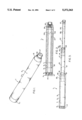
- FIG. 4 is an exploded view of the telescoping baton of the present invention.
- a telescoping baton of the present invention is indicated generally by reference numeral 1 in FIGS. 1-3.
- Baton 1 is shown in a collapsed state in FIGS. 1 and 2 and extended position in FIG. 3.
- Baton 1 is comprised of a handle section 3 which is formed of a cylindrical wall 5 defining an internal bore 7.
- Handle section 3 can be formed from an appropriate composite material such as nylon, polycarbonate, or kevlar.
- Bore 7 has a diameter slightly greater than the outside diameter of the second section as will be described below.
- Handle section 3 has threads 9 formed externally on the aft end for the threaded engagement of end cap 11.
- End cap 11 has internal threads 13 to engage threads 9.
- a cylindrical magnet 14 is positioned centrally in cap 11 to releasably secure the baton in a collapsed state as will be explained below.
- the forward end of handle 3 has a beveled head 15. Bore 7 is swaged down to reduce the diameter D within head 15.
- a second section 27 is formed from cylindrical wall 19 which defines an inner bore 21.
- Wall 19 has an outside diameter slightly less than diameter of bore 7 in handle 3 so that section 17 can fit within bore 7.
- Section 17 is formed from any appropriate composite material such as nylon, polycarbonate or kevlar. Forward end of section 17 has a bevelled head 23. Bore 21 is swaged down to reduce the diameter D2 at a point corresponding internally to bevel head 23.
- the aft section has an external collars 24 and 25.
- the outside diameter of collar 25 is essentially the same as diameter D in the forward end of bore 7 of handle section 3.
- An end section 27 is formed from cylindrical wall 29 which defines bore 31. Forward end of bore 31 has internal threads 33 to engage the threaded portion 35 of end plug 37. The aft end of section 27 has an external collar 32 and 33 formed thereon. Collar 33 has essentially the same outside diameter as the diameter D2 of the swaged end of bore 21 of middle section 17.
- Rod 39 An elongated iron rod 39 with an outside diameter slightly less than diameter of bore 31, is inserted into bore 31.
- Rod 39 has a circular end piece 41 integrally formed from iron. The diameter of end piece 41 is greater than the diameter of bore 31 so that the body of rod 39 fits within bore 31 while end piece 41 of abuts collar 33.
- Second section 17 fits within bore 7 of handle piece 3.
- End section 27 fits within bore 21 of second section 17.
- Collar 33 on end piece 27 engages the swaged section at diameter D2 of internal bore 21 of the second section thereby releasably locking it in place.
- collar section 25 of second section 17 engages the diameter D1 at the swaged end of internal bore 7 of handle 3 also locking it in place. This arrangement is best illustrated in FIG. 3.
- the user strikes the metallic end piece 37 against the floor or wall driving the collar sections 33 and 25 away from the swaged diameters D2 and D1 respectively thus allowing the telescoping sections to collapse within each other.
- Magnet 14 engages, section 41 of iron rod 39 as previously described.
Abstract
Description
Claims (2)
Priority Applications (3)
| Application Number | Priority Date | Filing Date | Title |
|---|---|---|---|
| US08/141,068 US5372363A (en) | 1993-10-26 | 1993-10-26 | Composite expandable baton with magnetic retaining means |
| US08/249,279 US5568922A (en) | 1993-10-26 | 1994-05-25 | Composite telescoping baton |
| US08/709,718 US5690552A (en) | 1993-10-26 | 1996-09-09 | Injection molded telescoping baton |
Applications Claiming Priority (1)
| Application Number | Priority Date | Filing Date | Title |
|---|---|---|---|
| US08/141,068 US5372363A (en) | 1993-10-26 | 1993-10-26 | Composite expandable baton with magnetic retaining means |
Related Child Applications (1)
| Application Number | Title | Priority Date | Filing Date |
|---|---|---|---|
| US08/249,279 Continuation-In-Part US5568922A (en) | 1993-10-26 | 1994-05-25 | Composite telescoping baton |
Publications (1)
| Publication Number | Publication Date |
|---|---|
| US5372363A true US5372363A (en) | 1994-12-13 |
Family
ID=22494029
Family Applications (1)
| Application Number | Title | Priority Date | Filing Date |
|---|---|---|---|
| US08/141,068 Expired - Fee Related US5372363A (en) | 1993-10-26 | 1993-10-26 | Composite expandable baton with magnetic retaining means |
Country Status (1)
| Country | Link |
|---|---|
| US (1) | US5372363A (en) |
Cited By (26)
| Publication number | Priority date | Publication date | Assignee | Title |
|---|---|---|---|---|
| US5509653A (en) * | 1993-09-30 | 1996-04-23 | Armament Systems And Procedures, Inc. | Expandable baton with resilient member mounted in tip |
| US5690552A (en) * | 1993-10-26 | 1997-11-25 | Ppct Products, Inc. | Injection molded telescoping baton |
| US5839967A (en) * | 1996-12-13 | 1998-11-24 | Baton Kinetics Incorporated | Impact baton having free-flow material and methods thereof |
| US6261188B1 (en) | 2000-01-20 | 2001-07-17 | Mark Badura | Expandable baton with handle grip cap |
| US20020082102A1 (en) * | 2000-09-29 | 2002-06-27 | Reilly Hugh A. | Exercise and stretching pole and method of using same |
| US20040132560A1 (en) * | 2003-01-03 | 2004-07-08 | Decelle Robert | Training bat |
| US20040160431A1 (en) * | 2003-02-07 | 2004-08-19 | Dimambro James | Pointer with non-scratch tip |
| US20040255995A1 (en) * | 2003-06-19 | 2004-12-23 | Garrett Melvin C. | Walking stick having shoehorn/gripper and magnet accessories |
| GB2406632A (en) * | 2004-09-15 | 2005-04-06 | Michael Maughan | Restraining truncheon |
| ITMI20081311A1 (en) * | 2008-07-18 | 2010-01-19 | Division System S R L | SUPPORTING STRUCTURE WITH VARIABLE CONFIGURATION WITH A HOLDING DEVICE AT AT LEAST ONE OF THE POSSIBLE CONFIGURATIONS, PARTICULARLY FOR THE SUPPORT OF SCREENS WITH RING TABLES OR SIMILAR IN COLLECTIVE ENVIRONMENTS. |
| WO2010121378A1 (en) * | 2009-04-20 | 2010-10-28 | Clive Milligan | Expandable baton for self-defense training |
| US8112851B1 (en) | 2010-10-04 | 2012-02-14 | Hughes Paul D | Casket with retractable handle |
| US20130150167A1 (en) * | 2011-12-13 | 2013-06-13 | Gary L. Pelkey | Multi-stage push button release baton |
| US20140256452A1 (en) * | 2013-03-06 | 2014-09-11 | Kantas Products Co., Ltd. | Expansion/collapse control mechanism for police baton |
| US20140298708A1 (en) * | 2013-04-03 | 2014-10-09 | Hard and Soft Fishing, Inc. | Adjustable fishing rod |
| US20140334131A1 (en) * | 2010-11-12 | 2014-11-13 | Glenn Bushee | Baton Light |
| CN105161378A (en) * | 2015-09-03 | 2015-12-16 | 国网山东省电力公司潍坊供电公司 | Self-suction anti-release handle |
| KR101734451B1 (en) * | 2015-01-27 | 2017-05-24 | 노봉환 | Police stick |
| US9677844B2 (en) | 2013-03-06 | 2017-06-13 | Starkey Industries, Llc | Telescoping baton with improved stopping and shock absorbing assembly |
| US9677843B2 (en) * | 2013-07-31 | 2017-06-13 | Armament Systems And Procedures, Inc. | Baton with recessed control button |
| US9719753B2 (en) * | 2013-07-31 | 2017-08-01 | Armament Systems And Procedures, Inc. | Baton with external control button |
| US10184650B1 (en) | 2016-09-15 | 2019-01-22 | Peacekeeper Products International LLC | Diversionary light end cap |
| US10247510B2 (en) | 2016-04-11 | 2019-04-02 | JDD Products, LLC | Composite whip |
| WO2020060899A1 (en) * | 2018-09-18 | 2020-03-26 | Armament Systems And Procedures, Inc. | Extendable baton with damage resistant locking mechanism |
| US10754450B2 (en) | 2018-12-28 | 2020-08-25 | Microsoft Technology Licensing, Llc | Adjustable stylus |
| WO2022047552A1 (en) * | 2020-09-04 | 2022-03-10 | Carlos Alberto Fernandes | Flexible retractable baton |
Citations (5)
| Publication number | Priority date | Publication date | Assignee | Title |
|---|---|---|---|---|
| CA543517A (en) * | 1957-07-16 | E. Ryden Carl | Fish knocker | |
| US4456255A (en) * | 1982-09-20 | 1984-06-26 | Braunhut Harold N | Spring whip defensive weapon |
| US4964636A (en) * | 1988-02-23 | 1990-10-23 | Hideyuki Ashihara | Police baton with rotatable crosshandle |
| US5160140A (en) * | 1989-09-28 | 1992-11-03 | Monadnock Lifetime Products, Inc. | Expandable baton with spring biased latch means |
| US5161800A (en) * | 1991-08-16 | 1992-11-10 | Armament Systems And Procedures, Inc. | Retainer clip for expanding baton |
-
1993
- 1993-10-26 US US08/141,068 patent/US5372363A/en not_active Expired - Fee Related
Patent Citations (5)
| Publication number | Priority date | Publication date | Assignee | Title |
|---|---|---|---|---|
| CA543517A (en) * | 1957-07-16 | E. Ryden Carl | Fish knocker | |
| US4456255A (en) * | 1982-09-20 | 1984-06-26 | Braunhut Harold N | Spring whip defensive weapon |
| US4964636A (en) * | 1988-02-23 | 1990-10-23 | Hideyuki Ashihara | Police baton with rotatable crosshandle |
| US5160140A (en) * | 1989-09-28 | 1992-11-03 | Monadnock Lifetime Products, Inc. | Expandable baton with spring biased latch means |
| US5161800A (en) * | 1991-08-16 | 1992-11-10 | Armament Systems And Procedures, Inc. | Retainer clip for expanding baton |
Cited By (36)
| Publication number | Priority date | Publication date | Assignee | Title |
|---|---|---|---|---|
| US5509653A (en) * | 1993-09-30 | 1996-04-23 | Armament Systems And Procedures, Inc. | Expandable baton with resilient member mounted in tip |
| US5690552A (en) * | 1993-10-26 | 1997-11-25 | Ppct Products, Inc. | Injection molded telescoping baton |
| US5839967A (en) * | 1996-12-13 | 1998-11-24 | Baton Kinetics Incorporated | Impact baton having free-flow material and methods thereof |
| US6261188B1 (en) | 2000-01-20 | 2001-07-17 | Mark Badura | Expandable baton with handle grip cap |
| US20020082102A1 (en) * | 2000-09-29 | 2002-06-27 | Reilly Hugh A. | Exercise and stretching pole and method of using same |
| US20040132560A1 (en) * | 2003-01-03 | 2004-07-08 | Decelle Robert | Training bat |
| US20060105864A1 (en) * | 2003-01-03 | 2006-05-18 | Decelle Robert | Training bat |
| US20040160431A1 (en) * | 2003-02-07 | 2004-08-19 | Dimambro James | Pointer with non-scratch tip |
| US6951224B2 (en) * | 2003-06-19 | 2005-10-04 | Garrett Melvin C | Walking support having shoehorn/gripper and magnet accessories |
| US20040255995A1 (en) * | 2003-06-19 | 2004-12-23 | Garrett Melvin C. | Walking stick having shoehorn/gripper and magnet accessories |
| GB2406632A (en) * | 2004-09-15 | 2005-04-06 | Michael Maughan | Restraining truncheon |
| GB2406632B (en) * | 2004-09-15 | 2005-08-31 | Michael Maughan | Restraining truncheon |
| ITMI20081311A1 (en) * | 2008-07-18 | 2010-01-19 | Division System S R L | SUPPORTING STRUCTURE WITH VARIABLE CONFIGURATION WITH A HOLDING DEVICE AT AT LEAST ONE OF THE POSSIBLE CONFIGURATIONS, PARTICULARLY FOR THE SUPPORT OF SCREENS WITH RING TABLES OR SIMILAR IN COLLECTIVE ENVIRONMENTS. |
| WO2010121378A1 (en) * | 2009-04-20 | 2010-10-28 | Clive Milligan | Expandable baton for self-defense training |
| US20120129613A1 (en) * | 2009-04-20 | 2012-05-24 | Clive Milligan | Expandable baton for self-defense training |
| US8568242B2 (en) * | 2009-04-20 | 2013-10-29 | Clive Milligan | Expandable baton for self-defense training |
| US8112851B1 (en) | 2010-10-04 | 2012-02-14 | Hughes Paul D | Casket with retractable handle |
| US9207040B2 (en) * | 2010-11-12 | 2015-12-08 | Glenn Bushee | Baton light |
| US20140334131A1 (en) * | 2010-11-12 | 2014-11-13 | Glenn Bushee | Baton Light |
| US8721459B2 (en) * | 2011-12-13 | 2014-05-13 | Starkey Industries, Llc | Multi-stage push button release baton |
| US20130150167A1 (en) * | 2011-12-13 | 2013-06-13 | Gary L. Pelkey | Multi-stage push button release baton |
| US20140256452A1 (en) * | 2013-03-06 | 2014-09-11 | Kantas Products Co., Ltd. | Expansion/collapse control mechanism for police baton |
| US8956235B2 (en) * | 2013-03-06 | 2015-02-17 | Kantas Products Co., Ltd. | Expansion/collapse control mechanism for police baton |
| US9677844B2 (en) | 2013-03-06 | 2017-06-13 | Starkey Industries, Llc | Telescoping baton with improved stopping and shock absorbing assembly |
| US20140298708A1 (en) * | 2013-04-03 | 2014-10-09 | Hard and Soft Fishing, Inc. | Adjustable fishing rod |
| US9603347B2 (en) * | 2013-04-03 | 2017-03-28 | Hard and Soft Fishing, Inc. | Adjustable fishing rod |
| US9719753B2 (en) * | 2013-07-31 | 2017-08-01 | Armament Systems And Procedures, Inc. | Baton with external control button |
| US9677843B2 (en) * | 2013-07-31 | 2017-06-13 | Armament Systems And Procedures, Inc. | Baton with recessed control button |
| KR101734451B1 (en) * | 2015-01-27 | 2017-05-24 | 노봉환 | Police stick |
| CN105161378A (en) * | 2015-09-03 | 2015-12-16 | 国网山东省电力公司潍坊供电公司 | Self-suction anti-release handle |
| US10247510B2 (en) | 2016-04-11 | 2019-04-02 | JDD Products, LLC | Composite whip |
| US10184650B1 (en) | 2016-09-15 | 2019-01-22 | Peacekeeper Products International LLC | Diversionary light end cap |
| WO2020060899A1 (en) * | 2018-09-18 | 2020-03-26 | Armament Systems And Procedures, Inc. | Extendable baton with damage resistant locking mechanism |
| US11585630B2 (en) | 2018-09-18 | 2023-02-21 | Armament Systems And Procedures, Inc. | Extendable baton with damage resistant locking mechanism |
| US10754450B2 (en) | 2018-12-28 | 2020-08-25 | Microsoft Technology Licensing, Llc | Adjustable stylus |
| WO2022047552A1 (en) * | 2020-09-04 | 2022-03-10 | Carlos Alberto Fernandes | Flexible retractable baton |
Similar Documents
| Publication | Publication Date | Title |
|---|---|---|
| US5372363A (en) | Composite expandable baton with magnetic retaining means | |
| US5690552A (en) | Injection molded telescoping baton | |
| US4132408A (en) | Weapon | |
| EP2604966B1 (en) | Multi stage baton with push button release | |
| US5509653A (en) | Expandable baton with resilient member mounted in tip | |
| US5356139A (en) | Expandable baton with sections made of dissimilar materials | |
| US6655372B1 (en) | Quick detachable gun barrel assembly | |
| US6238292B1 (en) | Push button controlled police baton with ball bearing locking mechanism | |
| US5149092A (en) | Locking means for extendable baton | |
| US4752072A (en) | Telescoping self-defense keychain | |
| US4964636A (en) | Police baton with rotatable crosshandle | |
| US10502522B2 (en) | Expandable baton with magnetic retention | |
| US4456255A (en) | Spring whip defensive weapon | |
| US5568922A (en) | Composite telescoping baton | |
| US7020994B2 (en) | Gun cleaning kit | |
| US5031827A (en) | Spring whip defensive mechanism having means to permit disassembly thereof | |
| US20090163286A1 (en) | Connecting structure of a shaft and a grip member of a golf club | |
| US5320348A (en) | Telescopic baton with shock absorbing means | |
| US5669370A (en) | Telescopic stabilizer | |
| US6231447B1 (en) | Push button controlled police baton | |
| US6334825B1 (en) | End cap assembly for thin wall metal ball bats | |
| US11585630B2 (en) | Extendable baton with damage resistant locking mechanism | |
| US6056643A (en) | Expandable baton | |
| US5666756A (en) | Shotgun having light weight interchangeable barrel tubes with improved fit | |
| US9182192B2 (en) | Reversible expandable baton |
Legal Events
| Date | Code | Title | Description |
|---|---|---|---|
| AS | Assignment |
Owner name: PPCT MANAGEMENT SYSTEMS, INC., ILLINOIS Free format text: ASSIGNMENT OF ASSIGNORS INTEREST;ASSIGNOR:SIDDLE, BRUCE K.;REEL/FRAME:007050/0951 Effective date: 19940627 |
|
| FPAY | Fee payment |
Year of fee payment: 4 |
|
| SULP | Surcharge for late payment | ||
| AS | Assignment |
Owner name: PPCT PRODUCTS LLC, FLORIDA Free format text: ASSIGNMENT OF ASSIGNORS INTEREST;ASSIGNORS:PPCT PRODUCTS, INC.;PPCT MANAGEMENT SYSTEMS, INC.;SIDDLER, BRUCE K.;REEL/FRAME:009893/0905 Effective date: 19990120 |
|
| FPAY | Fee payment |
Year of fee payment: 8 |
|
| REMI | Maintenance fee reminder mailed | ||
| LAPS | Lapse for failure to pay maintenance fees | ||
| STCH | Information on status: patent discontinuation |
Free format text: PATENT EXPIRED DUE TO NONPAYMENT OF MAINTENANCE FEES UNDER 37 CFR 1.362 |
|
| FP | Lapsed due to failure to pay maintenance fee |
Effective date: 20061213 |