US5378143A - Safety lighter - Google Patents
Safety lighter Download PDFInfo
- Publication number
- US5378143A US5378143A US07/965,152 US96515292A US5378143A US 5378143 A US5378143 A US 5378143A US 96515292 A US96515292 A US 96515292A US 5378143 A US5378143 A US 5378143A
- Authority
- US
- United States
- Prior art keywords
- pushbutton
- catch
- back end
- upper body
- burner
- Prior art date
- Legal status (The legal status is an assumption and is not a legal conclusion. Google has not performed a legal analysis and makes no representation as to the accuracy of the status listed.)
- Expired - Fee Related
Links
Images


Classifications
-
- F—MECHANICAL ENGINEERING; LIGHTING; HEATING; WEAPONS; BLASTING
- F23—COMBUSTION APPARATUS; COMBUSTION PROCESSES
- F23Q—IGNITION; EXTINGUISHING-DEVICES
- F23Q2/00—Lighters containing fuel, e.g. for cigarettes
- F23Q2/16—Lighters with gaseous fuel, e.g. the gas being stored in liquid phase
- F23Q2/164—Arrangements for preventing undesired ignition
-
- F—MECHANICAL ENGINEERING; LIGHTING; HEATING; WEAPONS; BLASTING
- F23—COMBUSTION APPARATUS; COMBUSTION PROCESSES
- F23Q—IGNITION; EXTINGUISHING-DEVICES
- F23Q2/00—Lighters containing fuel, e.g. for cigarettes
- F23Q2/34—Component parts or accessories
- F23Q2/46—Friction wheels; Arrangement of friction wheels
Definitions
- the present invention relates to a safety lighter providing safety operation, being capable of lighting only after a cocking operation.
- Currently manufactured gas lighters generally comprise a supply of liquified gas, an expander, a burner, and a flint-and-striking-wheel lighting assembly.
- the burner is moveable in translation, and depending on its position, expanded gas is allowed to flow or is prevented from flowing. It is known that the motion of the burner can be controlled by means of a tilting pushbutton on which the user's thumb bears, with burner motion taking place after causing the striking wheel to rotate (which wheel is in contact with the flint in conventional lighting).
- the tilting motion of the pushbutton raises the burner head, thereby allowing expanded gas to rise into the sparks.
- piezoelectric lighting is used, then the sparks are generated by applying pressure to a pushbutton which is a sliding member and which also allows gas to flow.
- the object of the present invention is to mitigate this drawback by making a lighter more difficult to light so that it can be lighted only after a determined and deliberate operation, and in particular so that a child cannot cause it to light.
- the invention seeks to increase operating safety for lighters, and also relates to the pushbutton of the lighter.
- a spring is generally provided beneath the pushbutton with the spring returning the burner to its rest position in which the flow of gas is cut off, with the gas flow channel being closed by a seal.
- the spring must be powerful enough to act via the pushbutton and the burner to cause the seal to be pressed adequately against its seat. However, for safety reasons, it turns out that the spring needs to be more powerful than is required for ensuring sealing so as to ensure that there is no danger of accidental lighting due, for example, to the pushbutton bearing against an obstacle inside a pocket.
- a second object of the present invention is to mitigate this drawback and to enable a powerful pushbutton spring to be used without damaging the burner seal.
- the safety lighter including a pushbutton is characterized in that it comprises, beneath the pushbutton, removeable locking means for preventing motion of the pushbutton, said locking means constituting a safety catch or tab, and being capable of being inserted in an opening provided in the rear portion of the pushbutton.
- the safety catch is preferably displaceable in a plane perpendicular to the longitudinal midplane of the lighter.
- the catch is fixed to means for automatically returning it to the locking position.
- These means may be constituted, for example, by a spring which is tensed when the user moves the catch to the operating position.
- the front end of the spring may be hooked to a hook, with a cam fixed to the pushbutton or a cam fixed to the catch enabling the spring to be disengaged from the hook, and with the spring being kept tense so long as pressure is applied to the pushbutton.
- the pushbutton of a liquified gas lighter is characterized in that its front portion includes a flexible zone and a rigid zone, with a stroke-limiting abutment projecting from the rigid zone towards the body of the lighter.
- the flexible zone which acts somewhat as a shock absorber when transmitting the force released by the pushbutton spring.
- the pressure on the seal is made independent of the force of the pushbutton spring, with the rigid zone or portion of the front portion of the pushbutton being stopped by the abutment. It is thus possible to mount a powerful spring on the lighter for satisfying safety requirements but without damaging the seal.
- the spring may exert a force of 15 newtons to 20 newtons while the force on the burner seal is kept down to 2 newtons or 3 newtons.
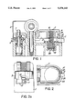
- FIG. 1 is a vertical section through the top portion of a safety lighter in accordance with the invention
- FIGS. 2 and 2a are respectively a plan view and a rear view of a lighter in the utilization position
- FIGS. 3 and 3a are corresponding views of the same lighter in the safety position
- FIG. 4 is a plan view of the rear portion of the lighter, with the pushbutton removed, and showing the latch in the utilization position;
- FIG. 5 is similar to FIG. 4, showing the latch in the safety position
- FIG. 6 is a vertical section through the top portion of a gas lighter in accordance with the invention when in its rest position;
- FIG. 7 is a half view in plan of the front portion of the same lighter.
- FIG. 1 shows conventional components used in lighter manufacture, and in particular the upper body surface on the top end of a main lighter body 1, a burner 3, and a knob 4 for adjusting the height of the flame, partially included inside a protective cover 2.
- the pushbutton or pushbutton member 7 is hinged to the body and has a pushbutton front end 27 which co-operates with the burner head 3.
- the pushbutton has a pushbutton back end which co-operates with a compression spring 8 disposed between the body 1 and the inside surface of the back end of the pushbutton.
- the depending backwall or rear sidewall 9 of the pushbutton includes an opening or notch 10.
- a locking means comprising a catch or lug 11 penetrates into the opening (in FIGS. 1, 2, and 2a which show the lighter in its operating position), said catch 11 being fixed to a ring 12 extending downwards in the form of a hub 13 rotatably received in a cavity 14 of the lighter body, which cavity also serves to receive one of the ends of the spring 8.
- the catch 11 is free to rotate through an angle of about 60° in a side slot 25 through the sidewall of the lighter body, and preventing operation thereof except when in the unlocked non-interfering position corresponding to the notch 10.
- the pushbutton 7 is free to move only when the catch is in its unlocked non-interfering position shown in FIGS. 1, 2, and 2a, thereby allowing gas to be released.
- FIGS. 2, 2a, 3, and 3a show a portion of a first embodiment of the lighter seen from above and from behind.
- FIG. 2 shows that the catch 11 is free to move between two abutment-forming portions of the body 1, bearing respective references 21 and 22 and limiting the stroke of the catch 11.
- the catch 11 has fluting 35 enabling it to be moved into the desired position.
- the means for automatically returning the catch to the safe position are constituted by a locked spring comprising a spiral spring 18 having a central ring 15.
- the spring 18 is prevented from rotating anticlockwise by a stud 16 or by any other means.
- the lug or catch 11 is fixed to the spring 18 and is guided, as before, through a slot or cut-out 25 between the body 1 and the pushbutton 7.
- a slight ramp may be provided on the pushbutton in order to facilitate engaging the catch 11 beneath the pushbutton when the catch returns to its safe or locking position, thereby assisting the action of the compression or pushbutton spring 8 and the spiral spring 18.
- the front portion 17 of the spiral spring 18 has a notch 20 constituting a retainer, and in the vicinity of the edge 21 of the body there is a hook 19.
- an external locking force e.g., applied by the user's finger
- the notch 20 latches behind the hook 19.
- the lighter is free to operate since its lug 11 is in an appropriate position, i.e. level with the notch 10.
- the lighter body 1 has the following, going from left to right: a passage in which the burner 3 is mounted together with the abutment 4 for adjusting flame height, and a fork 5 for receiving both the striking wheel (not shown) and a pin 6 on which the pushbutton 7 rocks.
- the pushbutton 7 engages the compression spring 8 which is imprisoned firstly in a cavity 7a formed in the pushbutton 7, and secondly on a guide stud 26 formed in the body 1.
- pressure on the top portion of the back end of the pushbutton 7 causes the pushbutton to pivot about its pin 6, thereby raising the front portion or end 27 of the pushbutton.
- the front portion 27 raises the burner head 3, and consequently the entire burner as shown in FIG. 6, thereby lifting the seal 28 which is fixed to the bottom portion 29 of the burner from its seat 30 on the chamber port and allowing gas to flow.
- the compression spring 8 is sufficiently stiff so that a downward external force must be applied to the pushbutton back end (e.g., by the user's finger) in order for the pushbutton front end 27 to unseat the burner 3 from the chamber port.
- the front portion 28 of the pushbutton 7 is constituted by two zones respectively 31 and 32, which are referred to below as the "flexible” zone 31 and as the "rigid” zone 32.
- this composite structure comes from a hollow 33 being cut out in the portion 27 (or being formed therein by molding).
- the stiffness of the zone 31 depends only on the mechanical strength of the line 37 at the boundary between the two zones 31 and 32.
- An abutment 38 projects downwards beneath the zone 32 to limit the stroke of the front portion 27 of the pushbutton 7. In general, this abutment bears against the body 1 of the lighter. In the example shown, it rests against an extension 39 of the adjustment knob 4.
- the flexible portion 31 has a rim 41 whose function is described below.
- a lighter provided with a pushbutton of the invention operates as follows:
- the bottom surface of the flexible zone 31 is located at a lower level than the bottom surface of the rigid zone 32. If the flexibility of the zone 31 is sufficient, the abutment 38 for making the end of the stroke of the rigid zone 32 may be omitted. In any event, it is deformation of the flexible zone which transmits the desired pressure to the seal. Naturally, the flexible zone could be a circular central zone projecting beneath the peripheral zone. If the pushbutton of the lighter is provided with a safety catch as mentioned above, it is necessary to leave a certain amount of clearance between the parts in order to allow them to move without friction. This means that the application of pressure on the pushbutton could allow gas to escape even with the safety catch in the safety position. However, the flexibility of the portion 31 deforms and prevents the seal 30 from being lifted off its seat.
Abstract
A safety catch (11) is moveable in a slot (25) of the lighter body (1) and a pushbutton (7) thereon cannot be pressed down unless the catch (11) is in a central position, with a spring returning the catch to the safe position automatically.
Description
This is a continuation of co-pending application Ser. No. 07/439,260 filed 17 Nov. 1989 parent application Ser. No. 07/439,260 is a continuation of the international application corresponding to PCT/FR 89/00339. PCT/FR 89/00339 corresponds to French national applications FR 88 08912 filed Jul. 1, 1988, and FR 88 09387 filed Jul. 11, 1988.
The present invention relates to a safety lighter providing safety operation, being capable of lighting only after a cocking operation.
Currently manufactured gas lighters generally comprise a supply of liquified gas, an expander, a burner, and a flint-and-striking-wheel lighting assembly. The burner is moveable in translation, and depending on its position, expanded gas is allowed to flow or is prevented from flowing. It is known that the motion of the burner can be controlled by means of a tilting pushbutton on which the user's thumb bears, with burner motion taking place after causing the striking wheel to rotate (which wheel is in contact with the flint in conventional lighting). The tilting motion of the pushbutton raises the burner head, thereby allowing expanded gas to rise into the sparks. When piezoelectric lighting is used, then the sparks are generated by applying pressure to a pushbutton which is a sliding member and which also allows gas to flow.
In general, manufacturers have sought to make lighting a lighter as simple as possible. However, such lighters present dangers if used by children.
The object of the present invention is to mitigate this drawback by making a lighter more difficult to light so that it can be lighted only after a determined and deliberate operation, and in particular so that a child cannot cause it to light. In general, the invention seeks to increase operating safety for lighters, and also relates to the pushbutton of the lighter.
In order to return the burner automatically towards its closed position, a spring is generally provided beneath the pushbutton with the spring returning the burner to its rest position in which the flow of gas is cut off, with the gas flow channel being closed by a seal.
The spring must be powerful enough to act via the pushbutton and the burner to cause the seal to be pressed adequately against its seat. However, for safety reasons, it turns out that the spring needs to be more powerful than is required for ensuring sealing so as to ensure that there is no danger of accidental lighting due, for example, to the pushbutton bearing against an obstacle inside a pocket.
It is therefore desired for the lighting of a lighter to take place only as a result of a deliberate action on the part of the user requiring a non-negligible amount of force to be applied to the pushbutton. Unfortunately, if the spring is very powerful, then its action is conveyed to the seal in the burner, thereby crushing it and damaging it. This gives rise to leaking which is dangerous and incompatible with normal operation.
A second object of the present invention is to mitigate this drawback and to enable a powerful pushbutton spring to be used without damaging the burner seal.
According to the present invention, the safety lighter including a pushbutton is characterized in that it comprises, beneath the pushbutton, removeable locking means for preventing motion of the pushbutton, said locking means constituting a safety catch or tab, and being capable of being inserted in an opening provided in the rear portion of the pushbutton.
In order to simplify identifying its position, the safety catch is preferably displaceable in a plane perpendicular to the longitudinal midplane of the lighter.
However, after lighting up, the user must return the safety catch to its locking position. Very frequently, this operation will be neglected or forgotten, thereby making the device ineffective since safety is achieved only if it is maintained permanently.
Thus, according to another characteristic of the present invention, the catch is fixed to means for automatically returning it to the locking position. These means may be constituted, for example, by a spring which is tensed when the user moves the catch to the operating position. However, in order to allow the user to light the lighter using one hand only, the front end of the spring may be hooked to a hook, with a cam fixed to the pushbutton or a cam fixed to the catch enabling the spring to be disengaged from the hook, and with the spring being kept tense so long as pressure is applied to the pushbutton.
According to another characteristic of the invention, the pushbutton of a liquified gas lighter is characterized in that its front portion includes a flexible zone and a rigid zone, with a stroke-limiting abutment projecting from the rigid zone towards the body of the lighter.
Contact between the front portion of the pushbutton and the burner head always takes place via the flexible zone which acts somewhat as a shock absorber when transmitting the force released by the pushbutton spring. Thus, the pressure on the seal is made independent of the force of the pushbutton spring, with the rigid zone or portion of the front portion of the pushbutton being stopped by the abutment. It is thus possible to mount a powerful spring on the lighter for satisfying safety requirements but without damaging the seal. For example, the spring may exert a force of 15 newtons to 20 newtons while the force on the burner seal is kept down to 2 newtons or 3 newtons.
Other characteristics and advantages of the invention appear from reading the following description of particular embodiments given purely by way of non-limiting example and with reference to the accompanying drawings, in which:
FIG. 1 is a vertical section through the top portion of a safety lighter in accordance with the invention;
FIGS. 2 and 2a are respectively a plan view and a rear view of a lighter in the utilization position;
FIGS. 3 and 3a are corresponding views of the same lighter in the safety position;
FIG. 4 is a plan view of the rear portion of the lighter, with the pushbutton removed, and showing the latch in the utilization position;
FIG. 5 is similar to FIG. 4, showing the latch in the safety position;
FIG. 6 is a vertical section through the top portion of a gas lighter in accordance with the invention when in its rest position; and
FIG. 7 is a half view in plan of the front portion of the same lighter.
FIG. 1 shows conventional components used in lighter manufacture, and in particular the upper body surface on the top end of a main lighter body 1, a burner 3, and a knob 4 for adjusting the height of the flame, partially included inside a protective cover 2. The pushbutton or pushbutton member 7 is hinged to the body and has a pushbutton front end 27 which co-operates with the burner head 3. The pushbutton has a pushbutton back end which co-operates with a compression spring 8 disposed between the body 1 and the inside surface of the back end of the pushbutton.
In accordance with the invention, the depending backwall or rear sidewall 9 of the pushbutton includes an opening or notch 10. A locking means comprising a catch or lug 11 penetrates into the opening (in FIGS. 1, 2, and 2a which show the lighter in its operating position), said catch 11 being fixed to a ring 12 extending downwards in the form of a hub 13 rotatably received in a cavity 14 of the lighter body, which cavity also serves to receive one of the ends of the spring 8. Thus, as can be seen more clearly in FIGS. 2a and 3a, the catch 11 is free to rotate through an angle of about 60° in a side slot 25 through the sidewall of the lighter body, and preventing operation thereof except when in the unlocked non-interfering position corresponding to the notch 10. The pushbutton 7 is free to move only when the catch is in its unlocked non-interfering position shown in FIGS. 1, 2, and 2a, thereby allowing gas to be released.
FIGS. 2, 2a, 3, and 3a show a portion of a first embodiment of the lighter seen from above and from behind. FIG. 2 shows that the catch 11 is free to move between two abutment-forming portions of the body 1, bearing respective references 21 and 22 and limiting the stroke of the catch 11. The catch 11 has fluting 35 enabling it to be moved into the desired position.
However, as mentioned above, it is desirable for the lighter to return automatically to the locked interfering or safe position after Sighting up. In order to achieve this aim, it is possible to use means as shown in FIGS. 4 and 5, respectively in the unlocked non-interfering or operating position and in the unlocked interfering or safe position, i.e. the position in which gas is prevented from flowing by virtue of the pushbutton 7 being locked.
In the example shown, the means for automatically returning the catch to the safe position are constituted by a locked spring comprising a spiral spring 18 having a central ring 15. The spring 18 is prevented from rotating anticlockwise by a stud 16 or by any other means. In this embodiment, the lug or catch 11 is fixed to the spring 18 and is guided, as before, through a slot or cut-out 25 between the body 1 and the pushbutton 7. A slight ramp may be provided on the pushbutton in order to facilitate engaging the catch 11 beneath the pushbutton when the catch returns to its safe or locking position, thereby assisting the action of the compression or pushbutton spring 8 and the spiral spring 18.
As can be seen in FIGS. 4 and 5, the front portion 17 of the spiral spring 18 has a notch 20 constituting a retainer, and in the vicinity of the edge 21 of the body there is a hook 19. When the lug 11 is moved to its operating position (FIG. 4) by application of an external locking force (e.g., applied by the user's finger) to the catch 11, the notch 20 latches behind the hook 19. The lighter is free to operate since its lug 11 is in an appropriate position, i.e. level with the notch 10.
When the user presses down the pushbutton 7, the surface 24 of the pushbutton (FIG. 1) bears against s tooth or cam 23 fixed to the lug 11, thereby urging it forwards, i.e. into the body of the lighter. This movement disengages the notch 20 from the hook 19. However, the cam 23 and the lug 11 remain held in place by the corresponding side of the notch 10. It is only after the pushbutton 7 has returned to its rest position under the action of the spring 8 that the lug 11 can escape into the slot 25, rotating under drive from the spring 18. The position taken up by the various components is then as shown in FIG. 5. Under the action of the spring 18, the lug 11 comes into abutment against the edge 22 of the slot 25, and before the lighter can be used again, the catch or lug 11 must be returned into alignment with the notch 10.
In FIG. 6 (from which the safety device has been omitted for reasons of clarity), the lighter body 1 has the following, going from left to right: a passage in which the burner 3 is mounted together with the abutment 4 for adjusting flame height, and a fork 5 for receiving both the striking wheel (not shown) and a pin 6 on which the pushbutton 7 rocks.
The pushbutton 7 engages the compression spring 8 which is imprisoned firstly in a cavity 7a formed in the pushbutton 7, and secondly on a guide stud 26 formed in the body 1. As in the prior art, pressure on the top portion of the back end of the pushbutton 7 causes the pushbutton to pivot about its pin 6, thereby raising the front portion or end 27 of the pushbutton.
The front portion 27 raises the burner head 3, and consequently the entire burner as shown in FIG. 6, thereby lifting the seal 28 which is fixed to the bottom portion 29 of the burner from its seat 30 on the chamber port and allowing gas to flow. The compression spring 8 is sufficiently stiff so that a downward external force must be applied to the pushbutton back end (e.g., by the user's finger) in order for the pushbutton front end 27 to unseat the burner 3 from the chamber port.
In accordance with a characteristic of the invention, the front portion 28 of the pushbutton 7 is constituted by two zones respectively 31 and 32, which are referred to below as the "flexible" zone 31 and as the "rigid" zone 32. As can be seen in FIG. 7, in the present example, this composite structure comes from a hollow 33 being cut out in the portion 27 (or being formed therein by molding). Thus, the stiffness of the zone 31 depends only on the mechanical strength of the line 37 at the boundary between the two zones 31 and 32.
An abutment 38 projects downwards beneath the zone 32 to limit the stroke of the front portion 27 of the pushbutton 7. In general, this abutment bears against the body 1 of the lighter. In the example shown, it rests against an extension 39 of the adjustment knob 4.
As can be seen in FIG. 6, the flexible portion 31 has a rim 41 whose function is described below.
A lighter provided with a pushbutton of the invention operates as follows:
After acting on the striking wheel, pressure is exerted on the back end of the pushbutton 7, thereby pivoting the pushbutton assembly and raising its front portion 27. The portion 31 of the pushbutton comes into contact with the bottom ring 40 of the burner 3 and raises it, thereby lifting the burner seal off its seat 30 and allowing gas to flow and be ignited. It has been observed that in spite of the resilience of the flexible zone 31, it is nevertheless capable of raising the burner head without difficulty. However, if this is not the case, i.e. if the portion 31 deflects too far, then the rigid zone takes over immediately for applying the required force.
After lighting a cigarette or the like, pressure on the back end of the pushbutton is released. Under the action of the previously compressed spring 8, the pushbutton pivots anticlockwise about its pin 6 and its portion 27 moves back down towards its rest position, thereby closing off the flow of gas by means of the burner seal 28. As it moves back down, the burner is driven by the rim 41 on the portion 31, since the rim projects down lower than the bottom surface of the rigid portion 32. This drive continues until the burner seal is pressed against its seat with adequate pressure. The abutment 38 then makes contact with the part 39 and further motion of the rigid portion 32 is prevented. The only pressure exerted on the burner is that from the rim 41, i.e. pressure due to the resilience of the line 37, and as mentioned above this pressure is limited in value.
In general, it is important that the bottom surface of the flexible zone 31 is located at a lower level than the bottom surface of the rigid zone 32. If the flexibility of the zone 31 is sufficient, the abutment 38 for making the end of the stroke of the rigid zone 32 may be omitted. In any event, it is deformation of the flexible zone which transmits the desired pressure to the seal. Naturally, the flexible zone could be a circular central zone projecting beneath the peripheral zone. If the pushbutton of the lighter is provided with a safety catch as mentioned above, it is necessary to leave a certain amount of clearance between the parts in order to allow them to move without friction. This means that the application of pressure on the pushbutton could allow gas to escape even with the safety catch in the safety position. However, the flexibility of the portion 31 deforms and prevents the seal 30 from being lifted off its seat.
The above description is Given in the context of a conventional flint lighter. However analogous means could be implemented for piezoelectric lighting, in which case the pushbutton would be a sliding component instead of a rocking component.
Claims (12)
1. A child resistant safety lighter comprising:
a main body having a chamber of combustible fluid, said chamber having an opening for release of said combustible fluid;
a burner member having a head portion at one end and a sealing means at the other end for sealing said combustible fluid in said chamber, said burner member being moveable into and out of sealing engagement with said chamber;
a pushbutton member having a pushbutton back end and a pushbutton front end, said pushbutton member being hinged for rotation to said main body intermediate said pushbutton front and back ends, said pushbutton front end being operatively connected to said burner and said pushbutton back end being adapted to rotate toward said main body, said pushbutton back end including a depending backwall having an upwardly extending notch formed therein;
a compression spring positioned to bias said pushbutton back end away from said main body, whereby said pushbutton front end is urged toward said main body to lower said burner into sealing engagement with said chamber;
locking means for preventing rotation of said pushbutton member to unseal said combustible fluid chamber, said locking means comprising a spring-loaded movable safety tab positioned between said main body and said depending backwall, said safety tab projecting outwardly of said main body between said main body and said depending backwall wherein, when said pushbutton is rotated to lower said burner into sealing engagement with said chamber, said pushbutton back end rotates away from said main body sufficiently so that a slot is defined by a clearance between sections of said main body and depending backwall adjacent to said safety tab, said slot opening into said notch and extending transversely with respect to the rotational plane of said pushbutton member, said safety tab defining an unlocked non-interfering position when located in the part of said slot opening into said notch thereby enabling rotation of said pushbutton back end toward said main body so that said notch becomes coextensive with said safety tab enabling said burner member to move out of sealing engagement with said chamber, said safety tab further defining a locked interfering position when located in said slot away from said notch wherein engagement between said safety tab and depending backwall obstructs rotation of said pushbutton back end toward said main body so that said burner remains in sealing engagement with said chamber, said safety tab being movable within said slot between said locked interfering position and said unlocked non-interfering position by opposing collinear forces which are parallel to the periphery of said main body adjacent to said slot and which lie in a plane perpendicular to said rotational plane, said spring of said spring-loaded safety tab resisting movement of said safety tab away from said locked interfering position to said unlocked non-interfering position;
said locking means further comprising tab retention means for holding said safety tab in its unlocked non-interfering position against said resistance of said spring of said spring-loaded safety tab and tab release means for automatically disengaging said tab retention means when said pushbutton back end is pivoted toward said upper body end sufficiently to move said burner member out of sealing engagement with said chamber, said safety tab being forced by said spring of said spring-loaded safety tab to automatically return said safety tab to said locked interfering position upon rotation of said pushbutton back end away from said main body sufficient to form said slot.
2. A child resistant safety lighter according to claim 1, wherein:
said spring-loaded movable safety tab comprises a spiral spring connected to said safety tab, said spiral spring having a fixed end and a free end, said spiral spring being in the relaxed state when said safety tab is in its locked interfering position and in a tensed state when said safety tab is in its unlocked non-interfering position within said notch.
3. A child resistant safety lighter according to claim 2, wherein:
said tab retention means comprises a notch formed in the free end of said spiral spring and a mating hook formed in said main body.
4. A child resistant safety lighter according to claim 3 wherein:
said tab release means comprises an upwardly extending inclined cam surface on said safety tab and a mating surface depending downwardly from said pushbutton back end adapted to engage said cam surface and force said spiral spring notch out of engagement with said body member hook as said pushbutton back end is depressed.
5. A child resistant safety lighter according to claims 1, 2, 3 or 4 wherein said compression spring exerts an upward force on said pushbutton back end greater than about 15 newtons.
6. A child resistant safety lighter according to claim 1 wherein said clearance is defined by a recess in said main body.
7. A safety lighter comprising:
a one-piece lighter body having an upper body end and a body side depending from said upper body end, said body having a chamber containing volatile fluid and a chamber port formed on said upper body end enabling combustible vapors to escape from said chamber;
a burner which closes said chamber port when seated thereon, said burner being supplied with combustible vapors from said chamber port when lifted up off said chamber port;
a pushbutton member having a pushbutton back end and a pushbutton front end,
said pushbutton member being hinged between said pushbutton back and front ends directly to said upper body end adjacent to said chamber port, said hinged connection enabling said pushbutton member to pivot about an axis wherein translation of said pushbutton back end toward and away from said upper body end produces concomitant travel of said pushbutton front end in the opposite direction,
said pushbutton front end interlocking with said burner so that displacement of said pushbutton back end toward said upper body end causes said burner to lift up off said chamber port and displacement of said pushbutton back end away from said upper body end causes said burner to seat on said chamber port;
a compression spring mounted directly on said upper body end and pushbutton back end wherein displacement of said pushbutton back end toward said upper body end is resisted by said compression spring;
a catch disposed between said upper body end and pushbutton back end., said catch projecting outwardly of said upper body end so that, when said catch is in a locked interfering position between said upper body end and pushbutton back end, said catch obstructs downward displacement of said pushbutton back end with respect to said upper body end and the associated upward displacement of said front end so that said burner remains seated on said chamber port,
said pushbutton back end and upper body end adjacent to said catch being shaped so that, when said catch is located in an unlocked non-interfering position between said upper body end and said pushbutton back end, said catch allows sufficient downward movement of said pushbutton back end with respect to said upper body end and associated upward movement of said pushbutton front end to unseat said burner from said chamber port and allow combustible vapors to flow from said chamber into said burner,
said pushbutton back end and said upper body end being shaped to define a clearance between sections of said upper body end and pushbutton back end adjacent to said catch when said pushbutton back end is sufficiently raised to cause said burner to seat on said chamber port, said catch being movable within said clearance between said locked interfering position and said unlocked non-interfering position by opposing collinear forces which are parallel to the periphery of said main body adjacent to said clearance and which lie in a plane which is perpendicular to said rotational plane;
a locking spring mounted directly on said catch and upper body end,
wherein said locking spring resists movement of said catch through said clearance toward said unlocked non-interfering position; and
a retainer fixed to said catch,
said retainer interlocking with said upper body end when said catch is in said unlocked non-interfering position to retain said catch in said unlocked non-interfering position against said resistance of said locking spring,
wherein, when said pushbutton back end is depressed sufficiently to cause said pushbutton front end to unseat said burner from said chamber port, said retainer disengages from said upper body end resulting in said locking spring forcing said catch to said locked interfering position when said pushbutton back end translates away from said upper body end sufficiently to enable formation of said clearance.
8. A safety lighter as set forth in claim 7, wherein said pushbutton back end includes a depending rear sidewall which engages said catch when said catch is in said locked interfering position so that said catch sufficiently obstructs said downward displacement of said back end with respect to said upper body end and associated upward displacement of said front end to prevent said front end from unseating said burner from said chamber port,
said rear sidewall having a notch which, when said catch is in said unlocked non-interfering position and said back end is downwardly displaced with respect to said upper body end, becomes coextensive with said catch to enable sufficient downward displacement of said back end and concomitant upward displacement of said front end to unseat said burner from said chamber port.
9. A safety lighter as set forth in claim 8, wherein said clearance is defined by a slot formed in said upper body end adjacent to said catch.
10. A safety lighter as set forth in claim 7, wherein said locking spring comprises a spiral spring having a fixed end and a free end, said spiral spring being relaxed when said catch is in said locked interfering position and being tensed when said catch is in said unlocked non-interfering position.
11. A safety lighter as set forth in claim 10, wherein said retainer comprises a retaining notch formed in said free end,
said retainer further comprising a mating hook formed on said upper body end which, when said catch is in said unlocked non-interfering position, grasps said retaining notch to retain said catch in said unlocked non-interfering position.
12. A safety lighter according to claim 11, wherein said retainer further comprises an inclined cam extending upwardly from said catch,
said retainer further comprising a mating surface depending downwardly from said pushbutton back end,
said mating surface engaging said cam when said back end is sufficiently close to said upper body end to cause said front end to unseat said burner from said chamber port,
said mating surface and cam being shaped so that their said engagement causes said retaining notch to separate from said mating hook, said spiral spring forcing said catch along said clearance to said locked interfering position when said back end is spaced sufficiently apart from said upper body end to enable formation of said clearance.
Priority Applications (1)
| Application Number | Priority Date | Filing Date | Title |
|---|---|---|---|
| US07/965,152 US5378143A (en) | 1988-07-01 | 1992-10-20 | Safety lighter |
Applications Claiming Priority (6)
| Application Number | Priority Date | Filing Date | Title |
|---|---|---|---|
| FR8808912A FR2633702B1 (en) | 1988-07-01 | 1988-07-01 | SAFETY LIGHTER |
| FR8808912 | 1988-07-01 | ||
| FR8809387A FR2634004A1 (en) | 1988-07-11 | 1988-07-11 | Push button for a lighter |
| FR8809387 | 1988-07-11 | ||
| US07/439,260 US5224854A (en) | 1988-07-01 | 1989-11-17 | Safety lighter |
| US07/965,152 US5378143A (en) | 1988-07-01 | 1992-10-20 | Safety lighter |
Related Parent Applications (1)
| Application Number | Title | Priority Date | Filing Date |
|---|---|---|---|
| US07/439,260 Continuation US5224854A (en) | 1988-07-01 | 1989-11-17 | Safety lighter |
Publications (1)
| Publication Number | Publication Date |
|---|---|
| US5378143A true US5378143A (en) | 1995-01-03 |
Family
ID=26226769
Family Applications (2)
| Application Number | Title | Priority Date | Filing Date |
|---|---|---|---|
| US07/439,260 Expired - Fee Related US5224854A (en) | 1988-07-01 | 1989-11-17 | Safety lighter |
| US07/965,152 Expired - Fee Related US5378143A (en) | 1988-07-01 | 1992-10-20 | Safety lighter |
Family Applications Before (1)
| Application Number | Title | Priority Date | Filing Date |
|---|---|---|---|
| US07/439,260 Expired - Fee Related US5224854A (en) | 1988-07-01 | 1989-11-17 | Safety lighter |
Country Status (5)
| Country | Link |
|---|---|
| US (2) | US5224854A (en) |
| EP (1) | EP0374246B1 (en) |
| JP (1) | JPH03501647A (en) |
| FI (1) | FI900918A0 (en) |
| WO (1) | WO1990000239A1 (en) |
Cited By (9)
| Publication number | Priority date | Publication date | Assignee | Title |
|---|---|---|---|---|
| US5492468A (en) * | 1991-10-22 | 1996-02-20 | Cirami; Salvatore | Child-resistant lighter with externally biased actuator |
| US5558514A (en) * | 1994-05-27 | 1996-09-24 | Hameur Et Cie | Safety latch for a lighter |
| US5676537A (en) * | 1996-04-23 | 1997-10-14 | Era Intermarketing Co., Inc. | Lockable spark generating device for a lighter |
| US6045354A (en) * | 1988-09-02 | 2000-04-04 | Bic Corporation | Selectively actuatable lighter |
| US6102689A (en) * | 1998-09-29 | 2000-08-15 | Man; Aman Chung Kai | Push button safety lighter |
| US20020150853A1 (en) * | 2001-03-20 | 2002-10-17 | Cowl Jeffrey David | Child resistant lighter |
| US20050170303A1 (en) * | 2002-05-22 | 2005-08-04 | Xinhua Huang | Laborsaving and safety cigarette lighter |
| US20090090745A1 (en) * | 2007-10-08 | 2009-04-09 | Blitz U.S.A., Inc. | Fuel can spout |
| US20100216081A1 (en) * | 2005-06-23 | 2010-08-26 | Pi-Design Ag | Bar lighter comprising a safety mechanism |
Families Citing this family (49)
| Publication number | Priority date | Publication date | Assignee | Title |
|---|---|---|---|---|
| US5215458A (en) * | 1988-03-04 | 1993-06-01 | Bic Corporation | Child-resistant lighter with spring-biased, rotatable safety release |
| US5435719A (en) * | 1988-09-02 | 1995-07-25 | Bic Corporation | Selectively actuatable lighter |
| US5584682A (en) | 1988-09-02 | 1996-12-17 | Bic Corporation | Selectively actuatable lighter with anti-defeat latch |
| US5002482B1 (en) | 1988-09-02 | 2000-02-29 | Bic Corp | Selectively actuatable lighter |
| US5427522A (en) * | 1988-09-02 | 1995-06-27 | Bic Corporation | Selectively actuatable lighter |
| US5445518A (en) * | 1988-09-02 | 1995-08-29 | Bic Corporation | Selectively actuatable lighter |
| FR2645626B1 (en) * | 1989-04-07 | 1994-06-03 | Swedish Match Consumer Product | GAS LIGHTER |
| JPH04363515A (en) * | 1990-10-03 | 1992-12-16 | Tokai:Kk | Gas lighter with safety device |
| JP2509047Y2 (en) * | 1990-10-22 | 1996-08-28 | タイ メリー カンパニー リミテット | lighter- |
| JPH0492142U (en) * | 1990-11-30 | 1992-08-11 | ||
| FR2671608A1 (en) * | 1991-01-10 | 1992-07-17 | Cricket Sa | IMPROVED CHILD-PROOF GAS LIGHTERS. |
| JPH0626647A (en) * | 1991-10-17 | 1994-02-04 | Masayuki Iwabori | Safeguard of lighter |
| JPH05106839A (en) * | 1991-10-17 | 1993-04-27 | Masayuki Iwabori | Safety device for lighter |
| JPH05106838A (en) * | 1991-10-17 | 1993-04-27 | Masayuki Iwabori | Safety device for lighter |
| JPH05126333A (en) * | 1991-11-01 | 1993-05-21 | Masayuki Iwabori | Safety device in lighter |
| JP2784966B2 (en) * | 1991-12-09 | 1998-08-13 | 株式会社東海 | Gas lighter with safety device |
| JP2784977B2 (en) * | 1992-01-13 | 1998-08-13 | 株式会社東海 | Gas lighter with safety device |
| JP2731884B2 (en) * | 1992-06-12 | 1998-03-25 | 株式会社東海 | Gas lighter with safety device |
| GB9215726D0 (en) * | 1992-07-24 | 1992-09-09 | Cli Claque Company Limited | Cigarette lighter |
| FR2705762B1 (en) * | 1993-05-28 | 1995-08-18 | Hameur Cie | Lighter security. |
| US5356286A (en) * | 1993-12-22 | 1994-10-18 | Polycity Industrial Ltd. | Child proof safety lock lighter |
| US5704776A (en) * | 1993-12-22 | 1998-01-06 | Polycity Industrial Ltd. | Safety lock lighter |
| JP2784145B2 (en) * | 1994-03-03 | 1998-08-06 | 株式会社東海 | Gas lighter with safety device |
| US5421720A (en) * | 1994-04-08 | 1995-06-06 | Polycity Industrial Ltd. | Safety lock lighter with sliding mechanism |
| US5407346A (en) * | 1994-04-11 | 1995-04-18 | Polycity Industrial Ltd. | Push type safety lock lighter |
| US5624254A (en) * | 1994-05-31 | 1997-04-29 | Capital Line Industries, Ltd. | Cigarette lighter |
| US5538417A (en) * | 1994-06-28 | 1996-07-23 | Cli-Claque Company Ltd. | Cigarette lighters |
| US5460516A (en) * | 1994-08-24 | 1995-10-24 | Polycity Industrial Ltd. | Safety lighter with locking striker wheel |
| US5645415A (en) * | 1995-06-14 | 1997-07-08 | Hamel; Gilles | Child-proof gas lighters and pens therewith |
| CN2224336Y (en) * | 1995-06-23 | 1996-04-10 | 北京市贝斯特实用技术研究所 | Self-locking type gas-lighter with automatic closing function |
| US5607295A (en) * | 1995-09-06 | 1997-03-04 | Thai Merry Co., Ltd. | Safety lock cigarette lighter |
| US5769625A (en) * | 1996-01-04 | 1998-06-23 | Polycity Industrial Limited | Safety lighter with smooth striker wheel edges |
| US5584683A (en) * | 1996-03-05 | 1996-12-17 | Polycity Industrial Limited | Safety lighter with striker wheel stopper |
| US5788476A (en) * | 1996-04-30 | 1998-08-04 | Polycity Industrial Ltd | Childproof piezoelectric lighter with sliding mechanism |
| US5846069A (en) * | 1996-08-20 | 1998-12-08 | Polycity Industrial Limited | Safety lighter with wheel hood |
| BR9812732A (en) | 1997-10-08 | 2000-08-22 | Minnesota Mining & Mfg | Dispensing valve cover |
| US6533576B1 (en) | 1999-03-03 | 2003-03-18 | Polycity Enterprise Limited | Lighter with child resistant actuating lever |
| US6095795A (en) * | 1999-05-03 | 2000-08-01 | Potskhishvili; David Vakhtangovich | Gas lighter with safety device |
| US6129543A (en) * | 1999-05-03 | 2000-10-10 | Potskhishvili; David Vakhtangovich | Gas lighter with safety device |
| US6053727A (en) * | 1999-08-24 | 2000-04-25 | Potskhishvili; David Vakhtangovich | Gas lighter with safety device |
| US6223791B1 (en) | 1999-10-21 | 2001-05-01 | 3M Innovative Properties Company | Gravity feed fluid dispensing valve |
| US6086358A (en) * | 1999-11-04 | 2000-07-11 | Potskhishvili; David Vakhtangovich | Piezoelectric gas lighter with safety device |
| WO2001038795A1 (en) | 1999-11-26 | 2001-05-31 | Cricket S.A. | Child resistant lighter |
| US6450214B1 (en) | 2001-08-31 | 2002-09-17 | 3M Innovative Properties Company | Gravity feed fluid dispensing valve |
| US20070287112A1 (en) * | 2006-06-12 | 2007-12-13 | I-Hsuan Lai | Safety lock of fire lighter |
| US8653942B2 (en) | 2008-08-20 | 2014-02-18 | John Gibson Enterprises, Inc. | Portable biometric lighter |
| KR101325527B1 (en) * | 2012-09-11 | 2013-11-07 | (주)연우 | Dispenser with a safety button |
| CA3041031A1 (en) | 2016-06-29 | 2018-01-04 | Worthington Industries, Inc. | Torch having a rotatable safety cap |
| US10502419B2 (en) | 2017-09-12 | 2019-12-10 | John Gibson Enterprises, Inc. | Portable biometric lighter |
Citations (49)
| Publication number | Priority date | Publication date | Assignee | Title |
|---|---|---|---|---|
| US1895032A (en) * | 1927-01-24 | 1933-01-24 | Thomas H Fisher | Portable lighting device and fuel therefor |
| US2520328A (en) * | 1949-01-11 | 1950-08-29 | Ronson Art Metal Works Inc | Cigar lighter locking mechanism |
| US2727376A (en) * | 1950-02-06 | 1955-12-20 | Brown & Bigelow | Pressurized pyrophoric gas lighter |
| US3169672A (en) * | 1963-01-23 | 1965-02-16 | Clayton Corp Of Delaware | Locking actuator cap for valved dispenser |
| FR2220047A1 (en) * | 1973-03-01 | 1974-09-27 | Dupont S T | |
| US3859035A (en) * | 1972-11-28 | 1975-01-07 | Ronson Corp | Gas lighter |
| US3924782A (en) * | 1974-12-23 | 1975-12-09 | Risdon Mfg Co | Safety closure assembly for capping a dispensing container |
| FR2280029A1 (en) * | 1974-07-26 | 1976-02-20 | Allumettes Ste Indle Forestier | Gas cigarette lighter with value control lever - has leaf spring integrally formed with lever or lighter body |
| US3961876A (en) * | 1974-06-06 | 1976-06-08 | Chernock Stephen P | Valve assembly |
| US4024988A (en) * | 1975-10-28 | 1977-05-24 | The Risdon Manufacturing Company | Safety closure assembly for an aerosol container |
| US4028043A (en) * | 1974-07-29 | 1977-06-07 | Genoud & Cie. | Cigarette lighter with presale tamper protection |
| US4049370A (en) * | 1974-09-24 | 1977-09-20 | Societe Anonyme Dite: Etablissements Genoud & Cie | Cigarette lighter with presale tamper protection |
| JPS52117197A (en) * | 1976-03-26 | 1977-10-01 | Omron Tateisi Electronics Co | Automatic premiums exchanging apparatus for game houses |
| US4157891A (en) * | 1974-09-04 | 1979-06-12 | Mansei Kogyo Kabushiki Kaisha | Fuel flow adjusting device for use in gas-fueled lighters |
| US4243377A (en) * | 1978-03-27 | 1981-01-06 | Paul Schmid | Fluid flow control valve |
| WO1981000752A1 (en) * | 1979-09-14 | 1981-03-19 | Cricket Sarl | Gas lighter |
| JPS5632749A (en) * | 1979-08-27 | 1981-04-02 | Fujitsu Ltd | Manufacture of semiconductor device |
| FR2468838A1 (en) * | 1979-10-30 | 1981-05-08 | Usiflamme Sa | GAS LIGHTER |
| US4295819A (en) * | 1977-08-12 | 1981-10-20 | Goro Sugiyama | Gas lighter |
| US4332549A (en) * | 1978-10-04 | 1982-06-01 | Scripto, Inc. | Gas pressure regulator for lighters |
| US4432542A (en) * | 1979-07-10 | 1984-02-21 | Poynter Products, Inc. | Joke cigarette lighter |
| US4471404A (en) * | 1982-08-12 | 1984-09-11 | Tokai Seiki Co., Ltd. | Movable electrode type electronic gas lighter |
| US4496309A (en) * | 1981-03-19 | 1985-01-29 | Schaechter Friedrich | Liquid gas-operated lighter, particularly pocket lighter |
| US4516933A (en) * | 1983-11-11 | 1985-05-14 | Enrico Buzzi | Household lighter |
| US4560345A (en) * | 1980-11-24 | 1985-12-24 | Schaechter Friedrich | Liquid gas-operated lighter |
| US4569654A (en) * | 1983-11-11 | 1986-02-11 | Enrico Buzzi | Dual purpose lighter for household use |
| US4595352A (en) * | 1982-11-18 | 1986-06-17 | Microtech Associates | Single-action ultra-thin cigarette lighter |
| US4717335A (en) * | 1986-08-28 | 1988-01-05 | Loveless Guy M | Child resistant lighter |
| DE8802582U1 (en) * | 1987-06-26 | 1988-04-14 | Pollyflame Int Bv | |
| US4758152A (en) * | 1987-06-01 | 1988-07-19 | Gary Michael Price | Safety mechanism for a cigar lighter |
| US4773849A (en) * | 1987-05-14 | 1988-09-27 | Schaechter Friedrich | Valve actuator for pocket lighter |
| EP0285748A1 (en) * | 1987-03-09 | 1988-10-12 | Tokai Corporation | Gas lighter equipped with a safety lock |
| US4784601A (en) * | 1987-03-09 | 1988-11-15 | Tokai Corporation | Gas lighter equipped with a safety lock |
| US4786248A (en) * | 1987-10-21 | 1988-11-22 | Tokai Corporation | Gaslighter equipped with a safety lock |
| US4799877A (en) * | 1988-06-13 | 1989-01-24 | Bisbee Jerry L | Child-proof adaptor for disposable butane cigarette lighter |
| US4822276A (en) * | 1988-06-13 | 1989-04-18 | Bisbee Jerry L | Child-proof cigarette lighter |
| US4830603A (en) * | 1988-03-04 | 1989-05-16 | Salvatore Cirami | Child-resistant disposable lighter |
| US4832596A (en) * | 1988-04-15 | 1989-05-23 | Morris Sr Glenn H | Child resistant cigarette lighter |
| US4850854A (en) * | 1987-10-02 | 1989-07-25 | Buck George S | Child resistant cigarette lighter |
| US4859172A (en) * | 1987-05-20 | 1989-08-22 | Tokai Corporation | Piezoelectric lighter equipped with a safety lock |
| US4869662A (en) * | 1987-01-16 | 1989-09-26 | Choice Products, Inc. | Flame-extinguishing device |
| US4869663A (en) * | 1988-09-22 | 1989-09-26 | Fremund Zdenek A | Child proof cigarette lighter |
| US4878836A (en) * | 1988-05-11 | 1989-11-07 | Tokai Corporation | Gaslighter structure |
| US4884965A (en) * | 1987-12-28 | 1989-12-05 | Tokai Corporation | Gaslighter structure permitting push-fit assembling of its main parts |
| US4889482A (en) * | 1987-05-14 | 1989-12-26 | Schaechter Friedrich | Valve actuator for pocket lighter |
| US4904180A (en) * | 1988-06-07 | 1990-02-27 | Tokai Corporation | Gaslighter equipped with a locking means to prevent undesired ignition |
| US4921420A (en) * | 1988-07-05 | 1990-05-01 | Johnston James A | Child resistant disposable lighter |
| US4992042A (en) * | 1988-03-31 | 1991-02-12 | Erka Gmbh | Multipurpose lighter |
| US5002482A (en) * | 1988-09-02 | 1991-03-26 | Bic Corporation | Selectively actuatable lighter |
Family Cites Families (1)
| Publication number | Priority date | Publication date | Assignee | Title |
|---|---|---|---|---|
| US4885965A (en) * | 1987-02-13 | 1989-12-12 | Ipco Corporation | Rotary saw for sectioning dental models |
-
1989
- 1989-06-29 JP JP1507812A patent/JPH03501647A/en active Pending
- 1989-06-29 EP EP89908222A patent/EP0374246B1/en not_active Expired - Lifetime
- 1989-06-29 WO PCT/FR1989/000339 patent/WO1990000239A1/en active IP Right Grant
- 1989-11-17 US US07/439,260 patent/US5224854A/en not_active Expired - Fee Related
-
1990
- 1990-02-23 FI FI900918A patent/FI900918A0/en not_active Application Discontinuation
-
1992
- 1992-10-20 US US07/965,152 patent/US5378143A/en not_active Expired - Fee Related
Patent Citations (63)
| Publication number | Priority date | Publication date | Assignee | Title |
|---|---|---|---|---|
| US1895032A (en) * | 1927-01-24 | 1933-01-24 | Thomas H Fisher | Portable lighting device and fuel therefor |
| US2520328A (en) * | 1949-01-11 | 1950-08-29 | Ronson Art Metal Works Inc | Cigar lighter locking mechanism |
| US2727376A (en) * | 1950-02-06 | 1955-12-20 | Brown & Bigelow | Pressurized pyrophoric gas lighter |
| US3169672A (en) * | 1963-01-23 | 1965-02-16 | Clayton Corp Of Delaware | Locking actuator cap for valved dispenser |
| US3859035A (en) * | 1972-11-28 | 1975-01-07 | Ronson Corp | Gas lighter |
| FR2220047A1 (en) * | 1973-03-01 | 1974-09-27 | Dupont S T | |
| US3938943A (en) * | 1973-03-01 | 1976-02-17 | S.T. Dupont | Security device for a portable lighter |
| US3961876A (en) * | 1974-06-06 | 1976-06-08 | Chernock Stephen P | Valve assembly |
| FR2280029A1 (en) * | 1974-07-26 | 1976-02-20 | Allumettes Ste Indle Forestier | Gas cigarette lighter with value control lever - has leaf spring integrally formed with lever or lighter body |
| US4028043A (en) * | 1974-07-29 | 1977-06-07 | Genoud & Cie. | Cigarette lighter with presale tamper protection |
| US4157891A (en) * | 1974-09-04 | 1979-06-12 | Mansei Kogyo Kabushiki Kaisha | Fuel flow adjusting device for use in gas-fueled lighters |
| US4049370A (en) * | 1974-09-24 | 1977-09-20 | Societe Anonyme Dite: Etablissements Genoud & Cie | Cigarette lighter with presale tamper protection |
| US3924782A (en) * | 1974-12-23 | 1975-12-09 | Risdon Mfg Co | Safety closure assembly for capping a dispensing container |
| US4024988A (en) * | 1975-10-28 | 1977-05-24 | The Risdon Manufacturing Company | Safety closure assembly for an aerosol container |
| JPS52117197A (en) * | 1976-03-26 | 1977-10-01 | Omron Tateisi Electronics Co | Automatic premiums exchanging apparatus for game houses |
| US4295819A (en) * | 1977-08-12 | 1981-10-20 | Goro Sugiyama | Gas lighter |
| US4243377A (en) * | 1978-03-27 | 1981-01-06 | Paul Schmid | Fluid flow control valve |
| US4332549A (en) * | 1978-10-04 | 1982-06-01 | Scripto, Inc. | Gas pressure regulator for lighters |
| US4432542A (en) * | 1979-07-10 | 1984-02-21 | Poynter Products, Inc. | Joke cigarette lighter |
| JPS5632749A (en) * | 1979-08-27 | 1981-04-02 | Fujitsu Ltd | Manufacture of semiconductor device |
| WO1981000752A1 (en) * | 1979-09-14 | 1981-03-19 | Cricket Sarl | Gas lighter |
| FR2465161A1 (en) * | 1979-09-14 | 1981-03-20 | Cricket Sa | GAS LIGHTER |
| AT372173B (en) * | 1979-09-14 | 1983-09-12 | Cricket Sarl | GAS LIGHTER |
| GB2072820A (en) * | 1979-09-14 | 1981-10-07 | Cricket Sa | Gas lighter |
| US4403945A (en) * | 1979-10-30 | 1983-09-13 | Usiflamme S.A. | Gas lighter for smokers |
| JPS5685638A (en) * | 1979-10-30 | 1981-07-11 | Usiflamme Sa | Gas lighter |
| CA1145658A (en) * | 1979-10-30 | 1983-05-03 | Imre Leitgib | Gas lighter |
| CH636943A5 (en) * | 1979-10-30 | 1983-06-30 | Usiflamme Sa | GAS LIGHTER. |
| GB2062200A (en) * | 1979-10-30 | 1981-05-20 | Usiflamme Sa | Gas-operated cigarette lighters |
| DE3040596A1 (en) * | 1979-10-30 | 1981-05-14 | Usiflamme S.A., Villars-sur-Glane | GAS LIGHTER |
| FR2468838A1 (en) * | 1979-10-30 | 1981-05-08 | Usiflamme Sa | GAS LIGHTER |
| US4560345A (en) * | 1980-11-24 | 1985-12-24 | Schaechter Friedrich | Liquid gas-operated lighter |
| US4496309A (en) * | 1981-03-19 | 1985-01-29 | Schaechter Friedrich | Liquid gas-operated lighter, particularly pocket lighter |
| US4471404A (en) * | 1982-08-12 | 1984-09-11 | Tokai Seiki Co., Ltd. | Movable electrode type electronic gas lighter |
| US4595352A (en) * | 1982-11-18 | 1986-06-17 | Microtech Associates | Single-action ultra-thin cigarette lighter |
| US4516933A (en) * | 1983-11-11 | 1985-05-14 | Enrico Buzzi | Household lighter |
| US4569654A (en) * | 1983-11-11 | 1986-02-11 | Enrico Buzzi | Dual purpose lighter for household use |
| US4717335A (en) * | 1986-08-28 | 1988-01-05 | Loveless Guy M | Child resistant lighter |
| US4869662A (en) * | 1987-01-16 | 1989-09-26 | Choice Products, Inc. | Flame-extinguishing device |
| US4784602A (en) * | 1987-03-09 | 1988-11-15 | Tokai Corporation | Gas lighter equipped with a safety lock |
| EP0285748A1 (en) * | 1987-03-09 | 1988-10-12 | Tokai Corporation | Gas lighter equipped with a safety lock |
| US4784601A (en) * | 1987-03-09 | 1988-11-15 | Tokai Corporation | Gas lighter equipped with a safety lock |
| US4889482A (en) * | 1987-05-14 | 1989-12-26 | Schaechter Friedrich | Valve actuator for pocket lighter |
| US4773849A (en) * | 1987-05-14 | 1988-09-27 | Schaechter Friedrich | Valve actuator for pocket lighter |
| US4859172A (en) * | 1987-05-20 | 1989-08-22 | Tokai Corporation | Piezoelectric lighter equipped with a safety lock |
| US4758152A (en) * | 1987-06-01 | 1988-07-19 | Gary Michael Price | Safety mechanism for a cigar lighter |
| EP0296281A1 (en) * | 1987-06-26 | 1988-12-28 | Pollyflame International B.V. | Lighter |
| DE8802582U1 (en) * | 1987-06-26 | 1988-04-14 | Pollyflame Int Bv | |
| US4850854A (en) * | 1987-10-02 | 1989-07-25 | Buck George S | Child resistant cigarette lighter |
| US4786248A (en) * | 1987-10-21 | 1988-11-22 | Tokai Corporation | Gaslighter equipped with a safety lock |
| EP0312627A1 (en) * | 1987-10-21 | 1989-04-26 | Tokai Corporation | Gaslighter equipped with a safety lock |
| US4884965A (en) * | 1987-12-28 | 1989-12-05 | Tokai Corporation | Gaslighter structure permitting push-fit assembling of its main parts |
| US4830603A (en) * | 1988-03-04 | 1989-05-16 | Salvatore Cirami | Child-resistant disposable lighter |
| US4992042A (en) * | 1988-03-31 | 1991-02-12 | Erka Gmbh | Multipurpose lighter |
| US4832596A (en) * | 1988-04-15 | 1989-05-23 | Morris Sr Glenn H | Child resistant cigarette lighter |
| US4878836A (en) * | 1988-05-11 | 1989-11-07 | Tokai Corporation | Gaslighter structure |
| US4904180A (en) * | 1988-06-07 | 1990-02-27 | Tokai Corporation | Gaslighter equipped with a locking means to prevent undesired ignition |
| US4822276A (en) * | 1988-06-13 | 1989-04-18 | Bisbee Jerry L | Child-proof cigarette lighter |
| US4799877A (en) * | 1988-06-13 | 1989-01-24 | Bisbee Jerry L | Child-proof adaptor for disposable butane cigarette lighter |
| US4921420A (en) * | 1988-07-05 | 1990-05-01 | Johnston James A | Child resistant disposable lighter |
| US5002482A (en) * | 1988-09-02 | 1991-03-26 | Bic Corporation | Selectively actuatable lighter |
| US5002482B1 (en) * | 1988-09-02 | 2000-02-29 | Bic Corp | Selectively actuatable lighter |
| US4869663A (en) * | 1988-09-22 | 1989-09-26 | Fremund Zdenek A | Child proof cigarette lighter |
Non-Patent Citations (6)
| Title |
|---|
| Certificate of Accuracy for Austrian Patent No. B 372 173 et al. * |
| Certificate of Accuracy for Canadian Patent No. A 1,145 658. * |
| Certificate of Accuracy for Canadian Patent No. A 1,145-658. |
| Certificate of Accuracy for French Patent Apllication No. 2 468 838. * |
| Certificate of Accuracy for French Patent Application No. 2 465 161 et al. * |
| Certificate of Accuracy for French Patent No. 79 26889. * |
Cited By (11)
| Publication number | Priority date | Publication date | Assignee | Title |
|---|---|---|---|---|
| US6045354A (en) * | 1988-09-02 | 2000-04-04 | Bic Corporation | Selectively actuatable lighter |
| US5492468A (en) * | 1991-10-22 | 1996-02-20 | Cirami; Salvatore | Child-resistant lighter with externally biased actuator |
| US5558514A (en) * | 1994-05-27 | 1996-09-24 | Hameur Et Cie | Safety latch for a lighter |
| US5676537A (en) * | 1996-04-23 | 1997-10-14 | Era Intermarketing Co., Inc. | Lockable spark generating device for a lighter |
| US6102689A (en) * | 1998-09-29 | 2000-08-15 | Man; Aman Chung Kai | Push button safety lighter |
| US20020150853A1 (en) * | 2001-03-20 | 2002-10-17 | Cowl Jeffrey David | Child resistant lighter |
| US20050170303A1 (en) * | 2002-05-22 | 2005-08-04 | Xinhua Huang | Laborsaving and safety cigarette lighter |
| US7364427B2 (en) * | 2002-05-22 | 2008-04-29 | Ningbo Xinhai Electronics Manufacture Co., Ltd. | Laborsaving and safety lighters |
| US20100216081A1 (en) * | 2005-06-23 | 2010-08-26 | Pi-Design Ag | Bar lighter comprising a safety mechanism |
| US20090090745A1 (en) * | 2007-10-08 | 2009-04-09 | Blitz U.S.A., Inc. | Fuel can spout |
| US8038035B2 (en) * | 2007-10-08 | 2011-10-18 | Blitz U.S.A., Inc. | Fuel can spout |
Also Published As
| Publication number | Publication date |
|---|---|
| WO1990000239A1 (en) | 1990-01-11 |
| EP0374246B1 (en) | 1993-02-24 |
| EP0374246A1 (en) | 1990-06-27 |
| FI900918A0 (en) | 1990-02-23 |
| US5224854A (en) | 1993-07-06 |
| JPH03501647A (en) | 1991-04-11 |
Similar Documents
| Publication | Publication Date | Title |
|---|---|---|
| US5378143A (en) | Safety lighter | |
| US5704776A (en) | Safety lock lighter | |
| CA2052821C (en) | Cigarette lighter | |
| US5368473A (en) | Gas lighter with safety device | |
| US5558514A (en) | Safety latch for a lighter | |
| US5460516A (en) | Safety lighter with locking striker wheel | |
| US5356286A (en) | Child proof safety lock lighter | |
| US5407346A (en) | Push type safety lock lighter | |
| US5421720A (en) | Safety lock lighter with sliding mechanism | |
| US5324193A (en) | Automatically lockable safety lighter for easy operation | |
| JP2784966B2 (en) | Gas lighter with safety device | |
| US5417571A (en) | Child resistant lighter | |
| JPH08502815A (en) | Lighter that can be operated selectively | |
| US6039561A (en) | Safety piezo-electric lighter | |
| US5607295A (en) | Safety lock cigarette lighter | |
| US5788474A (en) | Safety lighter | |
| US6129544A (en) | Safety device for piezoelectric lighter | |
| CA2095903C (en) | Gas lighter with safety device | |
| US5472338A (en) | Cigarette lighter safety with thumb locking mechanism | |
| ES2168239T3 (en) | LIGHTER THAT HAS A GUARD MEMBER AND BLOCKING MEMBERS. | |
| US5350294A (en) | Lighter | |
| US5387101A (en) | Cigarette lighters | |
| US5288226A (en) | Cigarette lighter | |
| EP0832395B1 (en) | Selectively actuatable lighter | |
| FR2633702A1 (en) | Safety lighter |
Legal Events
| Date | Code | Title | Description |
|---|---|---|---|
| FEPP | Fee payment procedure |
Free format text: PETITION RELATED TO MAINTENANCE FEES FILED (ORIGINAL EVENT CODE: PMFP); ENTITY STATUS OF PATENT OWNER: SMALL ENTITY Free format text: PETITION RELATED TO MAINTENANCE FEES GRANTED (ORIGINAL EVENT CODE: PMFG); ENTITY STATUS OF PATENT OWNER: SMALL ENTITY |
|
| FPAY | Fee payment |
Year of fee payment: 4 |
|
| SULP | Surcharge for late payment | ||
| FP | Lapsed due to failure to pay maintenance fee |
Effective date: 19990103 |
|
| PRDP | Patent reinstated due to the acceptance of a late maintenance fee |
Effective date: 19990205 |
|
| REMI | Maintenance fee reminder mailed | ||
| LAPS | Lapse for failure to pay maintenance fees | ||
| STCH | Information on status: patent discontinuation |
Free format text: PATENT EXPIRED DUE TO NONPAYMENT OF MAINTENANCE FEES UNDER 37 CFR 1.362 |
|
| FP | Lapsed due to failure to pay maintenance fee |
Effective date: 20030103 |