US5388686A - Lens case for contact lens disinfecting system - Google Patents
Lens case for contact lens disinfecting system Download PDFInfo
- Publication number
- US5388686A US5388686A US08/105,749 US10574993A US5388686A US 5388686 A US5388686 A US 5388686A US 10574993 A US10574993 A US 10574993A US 5388686 A US5388686 A US 5388686A
- Authority
- US
- United States
- Prior art keywords
- lens
- cap
- base plate
- cup
- case according
- Prior art date
- Legal status (The legal status is an assumption and is not a legal conclusion. Google has not performed a legal analysis and makes no representation as to the accuracy of the status listed.)
- Expired - Lifetime
Links
Images


Classifications
-
- A—HUMAN NECESSITIES
- A45—HAND OR TRAVELLING ARTICLES
- A45C—PURSES; LUGGAGE; HAND CARRIED BAGS
- A45C11/00—Receptacles for purposes not provided for in groups A45C1/00-A45C9/00
- A45C11/005—Contact lens cases
-
- Y—GENERAL TAGGING OF NEW TECHNOLOGICAL DEVELOPMENTS; GENERAL TAGGING OF CROSS-SECTIONAL TECHNOLOGIES SPANNING OVER SEVERAL SECTIONS OF THE IPC; TECHNICAL SUBJECTS COVERED BY FORMER USPC CROSS-REFERENCE ART COLLECTIONS [XRACs] AND DIGESTS
- Y10—TECHNICAL SUBJECTS COVERED BY FORMER USPC
- Y10S—TECHNICAL SUBJECTS COVERED BY FORMER USPC CROSS-REFERENCE ART COLLECTIONS [XRACs] AND DIGESTS
- Y10S134/00—Cleaning and liquid contact with solids
- Y10S134/901—Contact lens
Definitions
- This invention relates to improved storage and holding containers for small articles, particularly contact lens cases, adapted to contain solutions in which the contact lenses are immersed for disinfecting or cleaning.
- the widely-used soft contact lenses require protective storage containers which may also be used for disinfecting treatment of the lenses.
- Numerous commercially successful storage and disinfecting lens containers have been developed such as those described in U.S. Pat. Nos. 4,637,919 and 4,750,610 in which each lens of the pair is separately supported in a basket-like enclosure which is releasably latched in a closed or storage position and opens for access to the lens.
- the lenses are disinfected by immersion in a hydrogen peroxide solution.
- the hydrogen peroxide solution will have a strength of about which is sufficient to destroy most harmful bacteria.
- the system also employs a catalyst to decompose the hydrogen peroxide solution, into water and liberated oxygen.
- the resulting liberated oxygen requires a vent structure in order to prevent excessive pressure build-up within the lens case vessel.
- the end result, following decomposition of the hydrogen peroxide and venting of the liberated oxygen, is that no pressure remains in the lens case and the hydrogen peroxide (H 2 O 2 ) has been converted to water.
- the invention in accordance with the present application provides multiple improvements in the design of a lens case and solution container employed for lens disinfection.
- a contact remnants case includes a cup adapted to receive a quantity of disinfecting or cleaning solution and a cap removably closing the opening mouth of the cup.
- a lens support structure is associated with the cap and holds a pair of lenses within the cup.
- the lens support structure includes a base plate which supports one of a pair of the lenses on each side thereof and basket means pivotally connected to the base plate for enclosing the lenses in overlying position and maintaining the lenses on the base plate.
- a latch structure releasably maintains the basket means in the overlying position, and includes a flexible, integral extension peripherally formed on each basket means and is releasably retained in the overlying position by snap-fit against a hook member laterally projecting from the support structure.
- a pair of the flexible tabs are formed from vertically aligned and thinned notches on opposing edges of each basket, which are snap-fit against a corresponding pair of hooks.
- the latches for each basket are paired to prevent any slippage of the lens from the correctly centered position on the base plate which could lead to pinching of the lens during snap-fit opening or closing of the respective basket.
- the upper hook can extend from the lower surface of the cap in order to promote spacing of the upper latch from the base plate and supported lens.
- the cap is integrally formed with the base plate and both of the baskets are connected by integral, "live hinges" to the base plate so that the molded cap assembly and the cup are the only two pieces required for the lens case.
- the cup is provided with one or more sealing rings which bite into the cap in a closed position thereof to ensure sealed containment of the disinfecting solution and processing vertically spaced below threaded coupling of the cap upon the cup. Since the cap and lens support structure is an integral one-piece construction, a pair of mold parting line flash lenses are formed on the sealing surface of the cap. The sealing ring or rings will deform or cut into these flash lines to insure a proper seal.
- the cup is formed of a plastic material that is harder than that used on the cap, as explained hereinafter, to insure a good seal
- the plastic material selected for the cap will permit the cup to expand slightly under pressure. This expansion is such that excessive pressure build-up within the cup will be vented past the sealing rings. That is to say, the sealing rings enable elastic circumferential expansion away from the cap to intermittently relieve elevated pressure by allowing gaseous, self-regulated venting therebetween.
- a base plate having a lens support surface which is surrounded by an annular pattern of through apertures which intersect the circumference of a lens upon the support surface so that the apertures prevent development of a fluid seal and suction action during storage and facilitate removal of the lens from the support surface.
- the base plate can include an integrally extended coupler for mounting a conventional catalyst element thereon, in which the coupler includes a barbed-like retainer which prevents removal of the catalyst from the coupler once assembled.
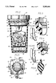
- FIG. 1 is an exploded perspective view of one embodiment of a lens case or container in accordance with the present invention
- FIG. 2 is a partially sectional view of the assembled lens case shown in FIG. 1;
- FIGS. 3 and 3A are enlarged, fragmentary, partially sectional views of a sealing portion of a cup wall and cap in the lens case of FIGS. 1 and 2;
- FIG. 4 is a sectional view similar to FIG. 3 showing sealing of the cup wall against the cap of the lens case;
- FIG. 4A is an enlarged, fragmentary view of the sealing impression formed in the cap by the sealing cup shown in FIG. 4;
- FIG. 5 is a fragmentary, plan view of a lens-supporting base portion of the lens case shown in FIGS. 1 and 2;
- FIG. 6 is a sectional view along a plane indicated by line 6--6 in FIG. 5;
- FIG. 7 is a fragmentary, side elevational view of basket portions closed against the lens supporting base portion as shown in FIG. 5;
- FIG. 8 is an enlarged, fragmentary view of a latch structure which retains the closed position of the basket portions against the base portion, Shown just prior to latching engagement;
- FIG. 9 is a fragmentary, sectional view similar to FIG. 8 showing the completed latching engagement
- FIG. 10 is a bottom, plan view of the integral cap and lens support structure as shown in FIG. 1;
- FIG. 11 is an enlarged, fragmentary view of the latching hook shown in FIGS. 8-10.
- FIG. 12 is an enlarged, fragmentary view of the coupler for the catalyst element of the lower end of the integral cap and lens support structure shown in FIG. 1, on which the catalyst element is mounted.
- FIG. 13 is a plan view of a second embodiment of an integral cap and lens support structure in accordance with the invention.
- FIG. 14 is a side elevational view of the cap and lens support structure shown in FIG. 13;
- FIG. 15 is a side view similar to FIG. 14 in which basket portions are pivoted and closed against the lens supporting base portion;
- FIG. 16 is an enlarged, fragmentary view of a latch structure which retains the closed position of the basket portions against the base portion of FIG. 15, shown just prior to latching engagement;
- FIG. 17 is a fragmentary, sectional view similar to FIG. 16 showing the completed latch engagements.
- FIG. 18 is a bottom, plan view of the integral cap and lens support structure as shown in FIG. 13.
- the lens case 10 comprises a container or cup 12 with a general cylindrical body and an upper collar portion thereof 14 which defines an open mouth or upper rim 15, and which facilitates molding of internal, annular sealing rims or shoulders 16 and 18 which provide fluid seals as more fully described hereinafter. Above the shoulders 16 and 18 are internal threads 20 which receive mating threads 22 on a removable screw cap 24 which closes the end opening of the collar 14 as shown in FIG. 2.
- the cap 24 is preferably molded integrally with a lens-supporting basket assembly generally designated by a reference character 26 which projects downwardly into the container 12 when the cap 24 is mounted thereon.
- the lens support basket assembly 26 includes a base plate 28 which supports one of a pair of contact lenses A (FIG. 6) on each side thereof, and has a structure more fully described in detail hereinafter.
- the base plate 28 is centrally located between hinged lens covers 30 and 32 which have a perforated, basket-like configuration to enable disinfecting or cleaning solution within the cup 12 to diffuse or pass through the basket-like covers and immerse the lenses.
- Each basket-like cover 30,32 has raised interior ribs 31,33 which protect the lens by spacing them from any hazardous molding flash remnant as more fully described in U.S. Pat. No. 4,981,657 the disclosure of which is incorporated by reference herein.
- the covers 30 and 32 are connected to the base plate 28 by integral, attenuated hinge portions or “live hinges” 34 and 36.
- the integral hinges 34 and 36 enable the respective covers 30 and 32 to pivot to a closed position engaged against the base plate 28 on respective opposite sides, and to releasably enclose respective lenses while allowing access for separate insertion or removal of each lens.
- the base plate 28 itself has a pair of opposing button-like convexed surfaces 27 which both share common through perforations 29 to enable enhanced solution flow therethrough and cleansing diffusion behind the lenses for thorough disinfection.
- Surrounding the convex surfaces 27 is an annular pattern of through apertures 25 which together with the perforations 29 promote perimeter breathing around the lens so that removal of the lens from the surface 27 is not impeded by any fluid sealing tendency for a suction action or vacuum development when the cap 24 and basket assembly 26 have been withdrawn from the solution in cup 12 and the covers 30 and 32 have been opened for lens access.
- the annular arrangement of the apertures 25 defines a maximum diameter D larger than the circumference of the average contact lens diameter, for example 13-17 mm.
- the combination of the perforations 29 and apertures 25 also promote drainage of previously used and exhausted solution to minimize contamination through carry-over into a new disinfection cycle.
- the lens supporting basket assembly 26 extends below the sealing rims or shoulders 16 and 18 and the disinfecting or cleaning solution is dispensed into the cup 12 only to a level L below the shoulders 16 and 18 which form a fluid seal above the immersed contact lenses but below the mating cup and cap threads 20,22.
- the threads 20,22 are thus isolated from any hydrogen peroxide solution spatter which may be created during the disinfection process particularly where gaseous turbulence is developed such as in oxygen liberation by decomposition of the hydrogen peroxide promoted by a typical catalyst element 38.
- the cleansing solution particularly hydrogen peroxide, cannot drip from the threads onto the lenses nor create an eye irritation hazard therefrom.
- the catalyst element 38 is mounted on a coupler 40 integrally molded below the base plate 28 as more fully described hereinafter.
- a latch structure is provided by a pair of attenuated or thinned and flexible tabs 42 integrally extending from each cover member at outside corners thereof (see FIG. 1) which cooperate with a pair of respective hook members 44 laterally projecting from base plate 28 to snap-fit over and releasably retain the tabs 42 and the closed, overlying position of the cover upon the base plate 28.
- the attenuated tabs 42 are formed as corner notches by mold inserts of variable tolerance to allow height adjustment for latch tightness and to compensate for mold wear.
- the tabs 42 are vertically aligned on opposing edges of the cover so that there can be no upper or lower gap in the closed position of the respective cover 30 or 32 which could allow migration or slippage of the lens A from the correctly centered position on the support surface 27 particularly during handling to insert or withdraw the support structure 26 from the cup 12, which could lead to pinching of the lens for example during snap-fit opening or closing of the respective cover member 30,32.
- the hook members 44 which are best understood from FIGS. 8-11, are paired to project from a respective side of the base plate 28 and positioned in adjacent corners thereof and remote from the support surface 27 and lens, as best shown in FIGS. 10 and 11.
- the hook surface 45 (FIG. 8) will engage the tab 42 to lock the member in engagement (FIG. 9).
- the surface of the hook member at right angles thereto, and which is most proximate to a lens supported on the surface 27, has a configuration sloping away from the surface 27 and is designated 47 in order to lead the surface of a misguided lens smoothly across the hook member 44 if inadvertently the lens is displaced from the support means against the hook member so that any lens damage by the hook is prevented. That is to say, as a lens is removed from the convex support 27, which is usually a sliding action, no sharp corners are presented by hook members 44 which could damage the lenses.
- each of the shoulders 16 and 18 has a sharp annular edge 46 and 48 respectively which bite or cut grooves 51 and 53 into and form a seal against an inwardly tapered, conical leading surface 50 of the cap 24 as the cap 24 is twisted into fully threaded, closed position as illustrated in FIGS. 2 and 4.
- two shoulder seals 16 and 18 are provided although optionally a single shoulder seal may be employed if sealing is sufficient.
- the biting seal by the shoulders 16 and 18 is facilitated by molding the cap 24 from a softer resin than the molded resin of the cup 12 and shoulders 16 and 18.
- the cap 24 (and integrally formed basket assembly 26) can be molded from a low density polypropylene such as El Paso Rexene® Polypropylene (R80 Rockwell Hardness) relative to molding of the cup 12 from high density polypropylene, for example Eastman Tenite® Polypropylene (R97 Rockwell Hardness) or Shell 6C Polypropylene (R84 Rockwell Hardness).
- a low density polypropylene such as El Paso Rexene® Polypropylene (R80 Rockwell Hardness) relative to molding of the cup 12 from high density polypropylene, for example Eastman Tenite® Polypropylene (R97 Rockwell Hardness) or Shell 6C Polypropylene (R84 Rockwell Hardness).
- the cup 12 must be sufficiently flexible to expand under internal pressure to relieve any pressure build-up that results from the liberated oxygen during decomposition.
- the unavoidable mold parting flash line 52 will result.
- the mold flash parting line 52 will extend the length of the cap/lens support assembly 12/26 and will be on opposite sides thereof. Most importantly, a portion of the flash parting line 52 will extend across the tapered sealing surface 50 (see FIG. 3A). The presence of this flash parting line can adversely affect the sealing action. To overcome this, the shoulders 16 and 18 with their respective sharp edges 46 and 48 formed from a harder material than the flash line 52, will cut through the flash line to insure attainment of a proper seal.
- the sharp shoulder edges 46 and 48 cut their own mating grooves 51 and 53 into the softer conical cap surface 50 so that the fluid seal is perfected despite the parting flash line 52 which has been cut or interrupted (FIG. 4A) by the edges 46 and 48 as well as compressed at 49 by the harder shoulders 16 and 18.
- elevated pressure generated by gaseous oxygen liberated from the decomposed hydrogen peroxide in the disinfecting solution can be vented through elastic circumferential expansion of the cup 12 and shoulders or sealing rims 16 and 18, for example at an internal pressure of approximately 20 psi, so that excessively high pressure cannot develop within the lens case.
- an optional feature of the catalyst mounting coupler 40 includes a conical pilot end 54 serving as a one-way, barbed-like retainer which allows mounting entry through the central bore of a conventional trigon platinum catalyst element 38 but also has an annularly recessed shoulder 56, behind the conical pilot end 54 which snaps against the internal annular ridge 58 of the trigon catalyst bore as shown in FIG. 12.
- a conical pilot end 54 serving as a one-way, barbed-like retainer which allows mounting entry through the central bore of a conventional trigon platinum catalyst element 38 but also has an annularly recessed shoulder 56, behind the conical pilot end 54 which snaps against the internal annular ridge 58 of the trigon catalyst bore as shown in FIG. 12.
- a second embodiment of the integrally molded cap 124 and lens-supporting basket assembly is generally designated by reference character 126, in accordance with the present invention.
- the cap 124 and basket assembly 126 can be used with the cup container 12 (FIGS. 1-4) of the first embodiment, and the conical, leading cap seal surface 150 accommodates biting seal by the annular cup edges 46 and 48 as shown in FIGS. 3-4.
- the cap 124 has a pair of diagonally spaced, upward projections or ears 124a which prevent a user from mistakenly setting an upside-down orientation of the assembled cap 124 and container-cup (12, FIG. 2).
- Such an inversion of the assembly similar to that shown in FIG. 2 could result in elevation of the mounted catalyst 138, on integral coupler 140, above the surface of the sterilization solution in which case the hydrogen peroxide content might not be fully decomposed to safe concentrations for direct contact of residues on the sterilized lens with the eye of the wearer.
- Arrangements alternative to the ears 124a may be employed in order to prevent inverted use of the cap 124 during the sterilization process.
- the upper latching hooks 144 extend from the bottom surface 160 of the cap 124 as best shown in FIGS. 13 and 16 and are located at the integral joint formed between the cap 124 and the medial stem portion 123 extending to the base plate 128.
- Each cover member 130 and 132 has a respective upper latch tab 142 which extends upwardly above the level of the lens support surfaces at an elevated spacing indicated by arrow E above the edge of the normally supported location of the lens A, as shown in FIG. 13. This spacing enables the latching and unlatching as illustrated in FIGS.
- Each of the cover members 130 and 132 also has a laterally extending finger tab generally adjacent to the respective latch tabs 142, which promote ease of the manual latching.
- the lower latch hooks 145 and latch tabs 147 are similarly spaced from the supported lens as shown in FIGS. 13-15.
- Each of the upper and lower hooks 144 and 145 has a sloping configuration in order to lead the surface of misguided lens during removal, smoothly across the hook in order to prevent lens damage by the hook (as earlier described with reference to FIG. 11).
- the scope of the invention is not limited by any particular embodiment but is defined by the appended claims and the equivalents thereof.
- the cap 24 can have a venting conduit formed therein (not shown) for release of pressurized gas generated by a lens disinfection process carried out within the lens case as more fully described in U.S. Pat. No. 4,637,919. While particular embodiments of the present invention have been described herein, it will be obvious to those skilled in the art that changes and modifications in various aspects may be made without departing from the broad scope of the invention.
Abstract
Description
Claims (23)
Priority Applications (1)
| Application Number | Priority Date | Filing Date | Title |
|---|---|---|---|
| US08/105,749 US5388686A (en) | 1993-02-02 | 1993-08-12 | Lens case for contact lens disinfecting system |
Applications Claiming Priority (2)
| Application Number | Priority Date | Filing Date | Title |
|---|---|---|---|
| US1381293A | 1993-02-02 | 1993-02-02 | |
| US08/105,749 US5388686A (en) | 1993-02-02 | 1993-08-12 | Lens case for contact lens disinfecting system |
Related Parent Applications (1)
| Application Number | Title | Priority Date | Filing Date |
|---|---|---|---|
| US1381293A Continuation-In-Part | 1993-02-02 | 1993-02-02 |
Publications (1)
| Publication Number | Publication Date |
|---|---|
| US5388686A true US5388686A (en) | 1995-02-14 |
Family
ID=21761891
Family Applications (1)
| Application Number | Title | Priority Date | Filing Date |
|---|---|---|---|
| US08/105,749 Expired - Lifetime US5388686A (en) | 1993-02-02 | 1993-08-12 | Lens case for contact lens disinfecting system |
Country Status (1)
| Country | Link |
|---|---|
| US (1) | US5388686A (en) |
Cited By (13)
| Publication number | Priority date | Publication date | Assignee | Title |
|---|---|---|---|---|
| US5609837A (en) * | 1995-08-16 | 1997-03-11 | Cerny; David E. | Disinfection apparatus |
| USD382400S (en) * | 1996-05-17 | 1997-08-19 | Spy Optic, Inc. | Sunglasses case |
| USD383602S (en) * | 1996-03-29 | 1997-09-16 | Spy Optic, Inc. | Sunglasses case |
| US5699900A (en) * | 1996-07-29 | 1997-12-23 | Artis; Derrick L. | Contact lens case with automatic counter |
| US6000534A (en) * | 1996-08-16 | 1999-12-14 | Allergan Sales, Inc. | Contact lens disinfecting device and disinfection system |
| US6076538A (en) * | 1997-12-01 | 2000-06-20 | Frankson; Jon | Kit for cleaning jewelry and other small parts |
| US6289907B1 (en) | 1999-02-04 | 2001-09-18 | Richard C. Horian | Device and method for cleaning contact lenses |
| US20030086830A1 (en) * | 2001-10-12 | 2003-05-08 | Becton Dickinson And Company | Method and apparatus for transporting biological samples |
| US20100233049A1 (en) * | 2009-03-16 | 2010-09-16 | Atrion Medical Products, Inc. | Additive effect enhanced hydrogen peroxide disinfection method and apparatus |
| US20110284399A1 (en) * | 2006-07-07 | 2011-11-24 | Donley Keith K | Dispensing contact lens cleaning liquid |
| US20120085662A1 (en) * | 2009-07-10 | 2012-04-12 | Menicon Co., Ltd. | Case for sterilizing contact lenses |
| USD753390S1 (en) * | 2012-01-18 | 2016-04-12 | Atrion Medical Products, Inc. | Contact lens case |
| US11207718B1 (en) | 2020-01-24 | 2021-12-28 | Tara Dominique Gumbs Martin | Method and apparatus for cleaning false eyelashes |
Citations (12)
| Publication number | Priority date | Publication date | Assignee | Title |
|---|---|---|---|---|
| US2117404A (en) * | 1936-03-26 | 1938-05-17 | Reeves Steel And Mfg Company | Holder for twin pails |
| US3519005A (en) * | 1968-07-29 | 1970-07-07 | Flow Pharma Inc | Contact lens cleaning and storage device |
| US3770113A (en) * | 1972-03-03 | 1973-11-06 | Mcd Corp | Contact lens holder |
| US3964926A (en) * | 1974-04-27 | 1976-06-22 | Koh-I-Noor Rapidograph, Inc. | Cleansing receptacle for capillary writing pen parts |
| US4011941A (en) * | 1975-04-28 | 1977-03-15 | Warner-Lambert Company | Contact lens capsule |
| US4109820A (en) * | 1977-06-09 | 1978-08-29 | International Paper Company | Self-threading container closure and method thereof |
| US4257521A (en) * | 1979-11-16 | 1981-03-24 | Stanley Poler | Packaging means for an intraocular lens |
| US4807750A (en) * | 1987-10-28 | 1989-02-28 | Ryder International Corporation | Latching structure for contact lens holder |
| US4890729A (en) * | 1989-04-25 | 1990-01-02 | Ryder International Corporation | Lens retaining apparatus |
| US4956156A (en) * | 1988-11-07 | 1990-09-11 | Ryder International Corporation | Pressure venting system for lens cases |
| US5186317A (en) * | 1992-02-04 | 1993-02-16 | Ryder International Corporation | Lens case for contact lens disinfecting system |
| US5196174A (en) * | 1989-06-09 | 1993-03-23 | Ciba Vision Corporation | Apparatus for sterilizing contact lenses |
-
1993
- 1993-08-12 US US08/105,749 patent/US5388686A/en not_active Expired - Lifetime
Patent Citations (12)
| Publication number | Priority date | Publication date | Assignee | Title |
|---|---|---|---|---|
| US2117404A (en) * | 1936-03-26 | 1938-05-17 | Reeves Steel And Mfg Company | Holder for twin pails |
| US3519005A (en) * | 1968-07-29 | 1970-07-07 | Flow Pharma Inc | Contact lens cleaning and storage device |
| US3770113A (en) * | 1972-03-03 | 1973-11-06 | Mcd Corp | Contact lens holder |
| US3964926A (en) * | 1974-04-27 | 1976-06-22 | Koh-I-Noor Rapidograph, Inc. | Cleansing receptacle for capillary writing pen parts |
| US4011941A (en) * | 1975-04-28 | 1977-03-15 | Warner-Lambert Company | Contact lens capsule |
| US4109820A (en) * | 1977-06-09 | 1978-08-29 | International Paper Company | Self-threading container closure and method thereof |
| US4257521A (en) * | 1979-11-16 | 1981-03-24 | Stanley Poler | Packaging means for an intraocular lens |
| US4807750A (en) * | 1987-10-28 | 1989-02-28 | Ryder International Corporation | Latching structure for contact lens holder |
| US4956156A (en) * | 1988-11-07 | 1990-09-11 | Ryder International Corporation | Pressure venting system for lens cases |
| US4890729A (en) * | 1989-04-25 | 1990-01-02 | Ryder International Corporation | Lens retaining apparatus |
| US5196174A (en) * | 1989-06-09 | 1993-03-23 | Ciba Vision Corporation | Apparatus for sterilizing contact lenses |
| US5186317A (en) * | 1992-02-04 | 1993-02-16 | Ryder International Corporation | Lens case for contact lens disinfecting system |
Cited By (27)
| Publication number | Priority date | Publication date | Assignee | Title |
|---|---|---|---|---|
| US5609837A (en) * | 1995-08-16 | 1997-03-11 | Cerny; David E. | Disinfection apparatus |
| USD383602S (en) * | 1996-03-29 | 1997-09-16 | Spy Optic, Inc. | Sunglasses case |
| USD382400S (en) * | 1996-05-17 | 1997-08-19 | Spy Optic, Inc. | Sunglasses case |
| US5699900A (en) * | 1996-07-29 | 1997-12-23 | Artis; Derrick L. | Contact lens case with automatic counter |
| US6000534A (en) * | 1996-08-16 | 1999-12-14 | Allergan Sales, Inc. | Contact lens disinfecting device and disinfection system |
| US6076538A (en) * | 1997-12-01 | 2000-06-20 | Frankson; Jon | Kit for cleaning jewelry and other small parts |
| US6289907B1 (en) | 1999-02-04 | 2001-09-18 | Richard C. Horian | Device and method for cleaning contact lenses |
| US20030086830A1 (en) * | 2001-10-12 | 2003-05-08 | Becton Dickinson And Company | Method and apparatus for transporting biological samples |
| US7147826B2 (en) * | 2001-10-12 | 2006-12-12 | Becton Dickinson And Company | Method and apparatus for transporting biological samples |
| US20070092412A1 (en) * | 2001-10-12 | 2007-04-26 | Becton Dickinson And Company | Apparatus for Transporting Biological Samples |
| EP3112025A1 (en) * | 2001-10-12 | 2017-01-04 | Becton, Dickinson and Company | Apparatus for transportimg biological samples |
| US8425864B2 (en) | 2001-10-12 | 2013-04-23 | Becton, Dickinson And Company | Apparatus for transporting biological samples |
| US8071058B2 (en) * | 2001-10-12 | 2011-12-06 | Becton, Dickinson And Company | Apparatus for transporting biological samples |
| US20110284399A1 (en) * | 2006-07-07 | 2011-11-24 | Donley Keith K | Dispensing contact lens cleaning liquid |
| US8371438B2 (en) | 2006-07-07 | 2013-02-12 | Keith K. Donley | Dispensing contact lens cleaning liquid |
| US20100233040A1 (en) * | 2009-03-16 | 2010-09-16 | Atrion Medical Products, Inc. | Additive effect enhanced hydrogen peroxide disinfection method and apparatus |
| US20100233041A1 (en) * | 2009-03-16 | 2010-09-16 | Atrion Medical Products, Inc. | Additive effect enhanced hydrogen peroxide disinfection method and apparatus |
| US8263016B2 (en) * | 2009-03-16 | 2012-09-11 | Atrion Medical Products, Inc. | Additive effect enhanced hydrogen peroxide disinfection method and apparatus |
| US8329098B2 (en) | 2009-03-16 | 2012-12-11 | Atrion Medical Products, Inc. | Additive effect enhanced hydrogen peroxide disinfection method and apparatus |
| US8329113B2 (en) | 2009-03-16 | 2012-12-11 | Atrion Medical Products, Inc. | Additive effect enhanced hydrogen peroxide disinfection method and apparatus |
| US8333931B2 (en) * | 2009-03-16 | 2012-12-18 | Atrion Medical Products, Inc. | Additive effect enhanced hydrogen peroxide disinfection method and apparatus |
| US20100233023A1 (en) * | 2009-03-16 | 2010-09-16 | Atrion Medical Products, Inc. | Additive effect enhanced hydrogen peroxide disinfection method and apparatus |
| US20100233039A1 (en) * | 2009-03-16 | 2010-09-16 | Atrion Medical Products, Inc. | Additive effect enhanced hydrogen peroxide disinfection method and apparatus |
| US20100233049A1 (en) * | 2009-03-16 | 2010-09-16 | Atrion Medical Products, Inc. | Additive effect enhanced hydrogen peroxide disinfection method and apparatus |
| US20120085662A1 (en) * | 2009-07-10 | 2012-04-12 | Menicon Co., Ltd. | Case for sterilizing contact lenses |
| USD753390S1 (en) * | 2012-01-18 | 2016-04-12 | Atrion Medical Products, Inc. | Contact lens case |
| US11207718B1 (en) | 2020-01-24 | 2021-12-28 | Tara Dominique Gumbs Martin | Method and apparatus for cleaning false eyelashes |
Similar Documents
| Publication | Publication Date | Title |
|---|---|---|
| US5388686A (en) | Lens case for contact lens disinfecting system | |
| US5114686A (en) | Contact lens disinfection unit with invertible lens holding baskets | |
| US4750610A (en) | Lens case with pressure sensitive venting system | |
| CA1330325C (en) | Contact lens disinfection unit | |
| EP0560917B1 (en) | Vented apparatus for storing and cleaning an element | |
| EP0368443B1 (en) | Container appliance with vent means | |
| CA2542425C (en) | Contact lens case | |
| US6148992A (en) | Lens case for contact lens disinfecting | |
| US4200187A (en) | Lens case with oppositely hinged baskets | |
| JP3942665B2 (en) | Contact lens disinfection device with improved exhaust means | |
| EP1094779B1 (en) | Oral feeding bottle | |
| US5186317A (en) | Lens case for contact lens disinfecting system | |
| US6000534A (en) | Contact lens disinfecting device and disinfection system | |
| US4981657A (en) | Contact lens case with raised, protective ribs | |
| AU655955B2 (en) | Contact lens case venting system | |
| EP1406677B1 (en) | Contact lens container | |
| JP2018515238A (en) | Pressure release container for disinfection and storage of contact lenses | |
| EP0309153B1 (en) | Contact lens disinfection case with locking mechanism | |
| CN216703010U (en) | Sterilizing container | |
| CA1313848C (en) | Container for storing contact lenses and conditioning them with a liquid that releases gas | |
| JP2004321256A (en) | Contact lens case | |
| JPH0223151Y2 (en) | ||
| JPH1081353A (en) | Container lid |
Legal Events
| Date | Code | Title | Description |
|---|---|---|---|
| AS | Assignment |
Owner name: RYDER INTERNATIONAL CORPORATION, ALABAMA Free format text: ASSIGNMENT OF ASSIGNORS INTEREST;ASSIGNORS:KANNER, ROWLAND W.;LISAK, STEPHEN P.;REEL/FRAME:006697/0278 Effective date: 19930810 |
|
| AS | Assignment |
Owner name: RYDER INTERNATIONAL CORPORATION, ALABAMA Free format text: CERTIFIED DOCUMENT - CERTIFICATION BY SECRETARY OF STATE OF ALABAMA ON BACK OF LAST PAGE;ASSIGNORS:RYDER INTERNATIONAL CORPORATION (A CORP. OF DELAWARE) (MERGED INTO);NEW RYDER CORPORATION (A CORP. OF ALABAMA) (CHANGED TO);REEL/FRAME:007147/0233 Effective date: 19921210 |
|
| AS | Assignment |
Owner name: RIC ACQUISITION CORPORATION, ALABAMA Free format text: ASSIGNMENT OF ASSIGNORS INTEREST;ASSIGNOR:RYDER INTERNATIONAL CORPORATION;REEL/FRAME:007167/0597 Effective date: 19940419 |
|
| AS | Assignment |
Owner name: RYDER INTERNATIONAL CORPORATION, ALABAMA Free format text: CHANGE OF NAME;ASSIGNOR:RIC ACQUISITION CORPORATION;REEL/FRAME:007194/0411 Effective date: 19940419 |
|
| STCF | Information on status: patent grant |
Free format text: PATENTED CASE |
|
| CC | Certificate of correction | ||
| AS | Assignment |
Owner name: REGENTS OF THE UNIVERSITY OF CALIFORNIA, CALIFORNI Free format text: ASSIGNMENT OF ASSIGNORS INTEREST;ASSIGNOR:HELLERSTEIN, MARC K., M.D., PH.D.;REEL/FRAME:008006/0294 Effective date: 19960613 |
|
| AS | Assignment |
Owner name: ATRION MEDICAL PRODUCTS, INC., ALABAMA Free format text: MERGER;ASSIGNOR:RYDER INTERNATIONAL CORPORATION;REEL/FRAME:008519/0569 Effective date: 19961211 |
|
| FPAY | Fee payment |
Year of fee payment: 4 |
|
| FEPP | Fee payment procedure |
Free format text: PAYOR NUMBER ASSIGNED (ORIGINAL EVENT CODE: ASPN); ENTITY STATUS OF PATENT OWNER: SMALL ENTITY |
|
| FPAY | Fee payment |
Year of fee payment: 8 |
|
| FPAY | Fee payment |
Year of fee payment: 12 |