US5389067A - Tampon applicator and method of making same - Google Patents
Tampon applicator and method of making same Download PDFInfo
- Publication number
- US5389067A US5389067A US08/173,142 US17314293A US5389067A US 5389067 A US5389067 A US 5389067A US 17314293 A US17314293 A US 17314293A US 5389067 A US5389067 A US 5389067A
- Authority
- US
- United States
- Prior art keywords
- petals
- bending
- individual petals
- cylindrical tube
- base region
- Prior art date
- Legal status (The legal status is an assumption and is not a legal conclusion. Google has not performed a legal analysis and makes no representation as to the accuracy of the status listed.)
- Expired - Lifetime
Links
Images


Classifications
-
- A—HUMAN NECESSITIES
- A61—MEDICAL OR VETERINARY SCIENCE; HYGIENE
- A61F—FILTERS IMPLANTABLE INTO BLOOD VESSELS; PROSTHESES; DEVICES PROVIDING PATENCY TO, OR PREVENTING COLLAPSING OF, TUBULAR STRUCTURES OF THE BODY, e.g. STENTS; ORTHOPAEDIC, NURSING OR CONTRACEPTIVE DEVICES; FOMENTATION; TREATMENT OR PROTECTION OF EYES OR EARS; BANDAGES, DRESSINGS OR ABSORBENT PADS; FIRST-AID KITS
- A61F13/00—Bandages or dressings; Absorbent pads
- A61F13/15—Absorbent pads, e.g. sanitary towels, swabs or tampons for external or internal application to the body; Supporting or fastening means therefor; Tampon applicators
- A61F13/20—Tampons, e.g. catamenial tampons; Accessories therefor
- A61F13/26—Means for inserting tampons, i.e. applicators
-
- Y—GENERAL TAGGING OF NEW TECHNOLOGICAL DEVELOPMENTS; GENERAL TAGGING OF CROSS-SECTIONAL TECHNOLOGIES SPANNING OVER SEVERAL SECTIONS OF THE IPC; TECHNICAL SUBJECTS COVERED BY FORMER USPC CROSS-REFERENCE ART COLLECTIONS [XRACs] AND DIGESTS
- Y10—TECHNICAL SUBJECTS COVERED BY FORMER USPC
- Y10S—TECHNICAL SUBJECTS COVERED BY FORMER USPC CROSS-REFERENCE ART COLLECTIONS [XRACs] AND DIGESTS
- Y10S604/00—Surgery
- Y10S604/904—Tampons
Definitions
- This invention relates to telescoping-type applicators which have a dome shaped forward end and are intended for the storage and ejection of tampons, and to the method of producing such applicators to optimize the force required for the user to conveniently eject the tampon pledget from the applicator.
- Tampon applicators which include a pair of telescoping cylinders are well known in the art.
- Berger, U.S. Pat. No. 3,895,634, assigned to the assignee of the subject application, and Voss U.S. Pat. No. 3,433,225 typically show such applicators in which the pledget is initially stored in the forward end of a cylindrical barrel.
- a lesser diameter plunger is telescopingly contained within the rear end of the barrel, such that the forward end of the plunger abuts the rear end of the pledget.
- the forward end of the barrel which is inserted in the vagina prior to tampon injection, includes a smooth, dome-shaped end for user comfort.
- the pledget When the user then urges the plunger against the rear end of the pledget, the pledget is moved forwardly in the barrel, opening up the petals which form the dome-shape forward end of the barrel, as the pledget is ejected from the barrel. Following the full ejection of the tampon pledget, the petals then return towards their original closed position so as to comfortably remove the applicator from the body orifice.
- tampon applicators are conventionally manufactured either of a suitable plastic composition, which is typically injection molded, or from cardboard. In view of environmental concerns, cardboard applicators, which are water degradable or water dispensable, are increasingly desirable.
- the force necessary to eject the tampon from a plastic applicator can be controlled by the composition and thickness of the plastic material, while maintaining the necessary structural integrity for the barrel.
- the cross-sectional wall thickness of the tubular portion of the barrel member and petals forming the dome-shaped insertion tip are different, to provide a relatively high strength side wall for the main body portion of the barrel and a relatively flexible and supple insertion tip. This provides the requisite stability for the barrel proper and an acceptable tampon ejection force.
- the petals forming the dome tip are reverse bent at their base region in a direction other than that required to thereafter form the dome tip. It has been determined that this will provide a significant reduction in the ejection force for their subsequent opening, while maintaining the structural rigidity of the tampon barrel, petal tip stability and the other requisite applicator characteristics.
- the cylindrical tube is first formed with the petals in alignment with the longitudinal axis of the cylindrical tube such that the forward end of the cylindrical tube is completely open.
- the petals are then bent radially inward towards the longitudinal axis of the cylinder, typically approximately 30 degrees.
- the petals are then bent radially outward in the opposite direction outside of the cylindrical volume defined by the cylindrical tube and beyond their original disposition, approximately an additional 30 degrees.
- the petals are then again moved inwardly towards the longitudinal axis, beyond the initial bending, and shaped to form the curved dome tip. During this reverse bending, there will be weakening of the cardboard at the base region of the petals.
- My method may be employed both in conjunction with, or without, a circumferential hinge groove at the base region of the petal. Where the groove is provided, the reduction in ejection force contributed by the groove is additive to that achieved by the petal bending of the instant invention, so as to further reduce the ejection force towards the desired magnitude.
- My invention may also be practiced in conjunction with that disclosed in Klesius, U.S. Pat. No. 5,290,501, which issued on Mar. 1, 1994, and assigned to the asignee of the instant application in which the petals are sprayed with a desired amount of moisture prior to final forming of their dome-shaped tip in order to provide increased petal stability during applicator storage.
- the petals are then curved inwardly to form the dome-shaped end. Thereafter, the petals are moved radially outward of the volume defined by the cylindrical tube such that they make an angle of approximately 30 degrees from their original disposition. The petals are then moved inwardly to again form the dome-shaped tip. While this alternative technique requires a more extensive initial step, and thereby may be somewhat more expensive to practice, it too will provide fiber weakening and hence a reduction in tampon ejection force.
- Still another alternative method which involves less steps and, correspondingly may provide a lesser magnitude of cardboard weakening and reduction in ejection force may be practiced.
- This alternative technique involves first bending the petals outward from their original position, parallel to the longitudinal axis of the barrel, and then bending the petals in the reverse direction inwardly to form the dome-shaped tip.
- a common theme present in all the methods for practicing my invention is the bending of the petals at their base region prior to the final formation of the dome tip. This sufficiently weakens the petals at their base region to obtain the requisite reduction in tampon pledget ejection force. Such weakening is achieved in conjunction with the other parameters of a particular cardboard applicator size so that the applicator possesses all the requisite parameters for acceptable performance.
- a further object is to provide such a method for forming a tampon applicator tube in which the petals are reverse bent about their base region prior to final fabrication of the dome-shaped tip.
- Another object of my invention is to provide a cardboard tampon applicator having a dome-shaped tip in which the cardboard fibers at the base region of the petals forming the dome-shape are weakened at their base region by prior inward and outward radial movement of the petals with such fiber weakening providing a significant reduction of the ejection force subsequently required to open the petals forming the dome-shaped closure and expel the pledget from the forward end of the barrel.
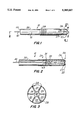
- FIG. 1 is a side view of an assembled tampon applicator, including the pledget contained therein, constructed in accordance with my invention.
- FIG. 2 is a cross-sectional view of the tampon applicator assembly shown in FIG. 1.
- FIG. 3 is an end view of the tampon applicator assembly, in the direction of arrows 3--3 as shown in FIG. 1.
- FIG. 4 shows a cardboard blank which may be used to form a pair of convolutely wound applicator barrels which are thereafter treated in accordance with my invention.
- FIG. 5 shows one of the barrels formed from the blank of FIG. 4, with the petals in the fully open condition, prior to forming the dome-shape, as shown in FIGS. 1-3.
- FIGS. 6A-6C show a preferred method of practicing my invention for sequentially forming the dome-shaped tip of the applicator from the initial condition shown in FIG. 5.
- FIGS. 7A-7C show some of the steps of an alternative method for sequentially forming the dome-shaped applicator from the initial condition shown in FIG. 5.
- FIGS. 8A and 8B sequentially shows some of the steps of a third embodiment of the method for forming the dome-shaped applicator from the cylindrical barrel shown in FIG. 5.
- FIG. 9 shows the production tool which may typically be used to thereafter transform the petals from the condition shown in FIG. 5 to that shown in FIG. 6A.
- FIG. 10 shows the production tool which may typically be used to transform the petals from the condition shown in FIG. 6A to that in 6B.
- FIG. 11 shows the production tooling for forming the petals into the dome-shaped tip.
- FIG. 12 refers to the second embodiment, and particularly how the petals 25 of the initially formed dome-shaped tip are then outwardly bent.
- the tampon assembly 10 includes a cylindrical tube which forms a barrel 20.
- a plunger 30 is telescopingly contained within the rear end portion of the barrel 20.
- a tampon pledget 40 which may partake of various known prior art pledget constructions, such as for example that shown in aforementioned Berger U.S. Pat. No. 3,895,634, is initially positioned within the main cylindrical body of the assembled barrel member 20.
- a withdrawal string 42 extends outwardly through the central portion of the plunger 30 for subsequent removal of the pledget from the user's body after ejection from the applicator assembly, and removal of the applicator from the user's body.
- the forward end 31 of the plunger typically abuts the rear end 43 of the pledget for moving the pledget forward, in the conventional manner so as to eject the pledget 40 from the forward end of the barrel.
- the barrel 20 includes a dome shaped forward end 24 which is provided for more comfortable insertion of the applicator.
- the dome end is typically shown as comprising six individual petals 25 which are curved inwardly at their base region. Although six petals are shown a different number of petals may be employed, as is well known in the art.
- a circumferential groove, shown as 27 is preferably provided around the inward surface at the petal base region.
- the groove 27, which is preferably on the blank 50 (see FIGS. 4), while it is in the flat state may preferably be formed by a pair of complementary mandrels (not shown), which contact opposite surfaces of the blank.
- One such mandrel includes a circumferential projection corresponding to the groove to be formed at the base region.
- the other has a complementary circumferential recess.
- the coaction of the two mandrels crush the fibers at the petal base region, thereby providing a hinge point to facilitate inward bending of the petals to their required dome configuration.
- the groove may be formed on the outside of the cylindrical barrel, or the groove may be omitted, with the requisite reduction in expulsion force being obtained by the appropriate characteristics of the cardboard, in conjunction with the initial bending of the petals at their base region 26 in accordance with my invention.
- the radial slits 28 between the sides of the petals prefferably extend somewhat below the base region 26 of the petals, and the circumferential groove 27 at the base region.
- This allows for tolerances with respect to anticipated manufacturing variations in the location of the groove.
- the circumferential groove 27 is not below the terminus of the radial slit 28.
- a finger grip section 29 is advantageously provided at the rear end of the barrel so as to facilitate the user's grasping and maintaining the applicator during pledget ejection, particularly if the outer surface of the applicator is made smooth, to aid in comfortable applicator insertion.
- the fingergrip may be formed by a plurality of score lines, such as for example, typically shown in aforementioned Wiegner et al. U.S. Pat. No. 4,412,833, or Jaycox U.S. Pat. No. 3,696,812. Although eight score lines are shown in FIG. 1, other numbers may be used, depending upon such factors as the thickness and smoothness of the cardboard forming the barrel 20.
- FIG. 4 shows a blank 50 used to fabricate a preferred form of the barrel 20 in accordance with my invention.
- a pair of barrels 20 will be convolutely wound from blank 50.
- spiral wound barrels may also be employed in conjunction with my invention.
- the blank 50 it is advantageous to first form the blank 50 of a length to fabricate two barrels 20. That is, the blank 50 which is naturally twice the length of a single barrel, includes the petals 25 at each of its ends.
- the blank 50 forming the barrel, as well as the plunger 30, are made of a laminated paper/paper board stock. The radially inward laminates provide the requisite form and rigidity. The outermost layer is selected to provide appropriate smoothness and whiteness.
- the inner plies may additively be in the order of 0.0135 inches thick, with the outer ply being a wax coated paper stock in the order of 0.0018 inches thick.
- a thicker ply would typically be used for larger diameter size tampon pledgets, which likewise include a somewhat greater diameter barrel.
- the circumferential groove 27 is preferably embossed on the blank while it is in the flat state. Groove 27, is typically 0.02 inches wide, and 0.004-0.010 inches deep. This circumferential groove 27 may typically be 0.020-0.030 inches above the terminus of radial slit 28 as shown by the distance X in FIG. 4.
- the blank 50 is rolled into a cylinder and the opposite ends 52-54 which overlap are glued together.
- the unit is then cut along mid-section 55 to provide two identical barrels 20 in which the petals 25 extend forwardly in alignment with the longitudinal axis 15 of the barrel.
- the forward end 24 of the barrel 20 would then only be presented against the petal forming tool 60 as shown in FIG. 11 which includes an inwardly concave surface 62 corresponding to the dome-shaped lip.
- the tool 60 may be heated, typically to about 350 degrees Fahrenheit. This is particularly desirable if the outer coating of the barrel includes a thermo-sensitive material, as is disclosed in Whitehead, U.S. Pat. No.
- Mandrel 51 which may not be independently heated, is inserted within the barrel 20.
- Mandrel 51 has a forward curved end which is complementary to the concavity 63 of the heated forming tool 60.
- the petal tips sequentially go through the steps shown in FIGS. 5, 6A, 6B and 6C.
- the cylindrical barrel with open petals 25 as shown in FIG. 5 is first presented to the forming tool 64 shown in FIG. 9.
- Forming tool 64 includes an inner concave surface 65 into which the petals 25 are only partially inserted so they are bent inwardly, but not closed, to the condition shown in FIG. 6A.
- the inward bending petals, as shown by angle A may be in the order of 30 degrees.
- the forward end of the barrel 20 is then presented to forming tool 66 as shown in FIG. 10.
- Forming tool 66 includes an outwardly cone shape forming surface 67 which is inserted within the open end of the barrel so as to outwardly deflect the petals 25 outside of the cylindrical colume defined by the cylindrical tube or barrel 20, as shown in FIG. 6B.
- the angle B, through which the petals are reversed in the opposite direction may also be in the order of 30 degrees.
- other magnitudes of inward and outward deflection of the petals 25 may be practiced, according to the characteristics of the cardboard forming the barrel 20, whether the circumferential hinge 27 is included, the dimensions of the barrel and petals and the desired final ejection pressure.
- Tool 60 includes inward concave surfaces 61, which are preferably heated (typically in the order of 350 degrees Fahrenheit), which curves the individual petals 25 to partake of the configuration shown in 6C which, corresponds to the dome-shaped forward end of the barrel 20 in the completed assembly 10, shown in FIGS. 1-3.
- the pledget 40 and plunger 30 are then inserted through the rear of the barrel 20 to provide the complete operative assembly.
- the assembly 10 is then typically wrapped in an individually sealed package, as for example shown in Ingersoll, et al. U.S. Pat. No. 4,617,781, assigned to the assignee of the instant application.
- FIGS. 5, 6C, 12 and 11 sequentially follows the steps shown in FIGS. 5, 6C, 12 and 11.
- the open forward end 24 of the open barrel 20, as shown in FIG. 5 is first formed to the dome tip as shown in FIG. 6C such as by tools 51 and 60 shown in FIG. 11.
- the petals 25 are then opened outwardly to the condition shown in FIG. 12. This may be performed as shown in FIG. 12 by a spherical shape mandrel 69 which is inserted within the barrel 20 from the rear end so as to move the petals 25 outwardly.
- the manual 69 is then removed and the petals reverse formed inwardly to the condition shown in FIG. 11.
- FIGS. 5, 6C, 12 and 11 sequentially follows the steps shown in FIGS. 5, 6C, 12 and 11.
- this alternative method likewise radially bends the petals 25 in both directions about their base region prior to final tip fabrication, with this embodiment including the step of first preforming the petals into the dome-shape.
- This alternative embodiment also provides for petal weakening, and hence a reduction in ejection force.
- FIGS. 8A and 8B Still a further, and simpler method is shown in the alternative embodiment, of FIGS. 8A and 8B.
- the petals of the barrel are modified from the condition shown in FIG. 5 to an outward bending as shown in FIG. 8A, (which generally corresponds to FIGS. 7A and 6B).
- This outward bending may be accomplished by a tool such as 66 shown in FIG. 10.
- the petals are then moved inwardly to form the dome-shaped configuration shown in FIG. 8B, such as by tools 51 and 60 of FIG. 11.
- an intermediate step may be included of first bending the petals inwardly, such as generally corresponding to the condition of FIGS. 6A or 7C, before their final shaping to the dome configuration.
- the angle C of outward deflection as shown in FIG. 8A may be increased, from the 30 degrees shown by angle B in FIG. 6B, due to the lesser number of steps, in order to achieve the requisite degree of petal weakening and reduction in ejection force.
- the particular method selected, and extent of petal deflection prior to forming naturally depends upon the characteristics of the particular cardboard stock selected for forming the barrel, the measured ejection force without incorporating the steps of my invention, whether or not a circumferential groove is provided at the base region of the petals, and the desired degree of ejection reduction.
- my invention advantageously provides an effective method for achieving the requisite ejection force. Further, it should be appreciated that by varying the steps, as shown by the different methods disclosed, as well as the degree of petal bending, the reduction of ejection force can be adjusted according to the characteristics of the cardboard forming the applicator and size of the barrel 20 and petals 25.
Abstract
Description
Claims (13)
Priority Applications (2)
| Application Number | Priority Date | Filing Date | Title |
|---|---|---|---|
| US08/173,142 US5389067A (en) | 1992-05-20 | 1993-12-22 | Tampon applicator and method of making same |
| US08/976,527 US6024716A (en) | 1992-05-20 | 1997-11-21 | Tampon applicator and method of forming same |
Applications Claiming Priority (2)
| Application Number | Priority Date | Filing Date | Title |
|---|---|---|---|
| US88611492A | 1992-05-20 | 1992-05-20 | |
| US08/173,142 US5389067A (en) | 1992-05-20 | 1993-12-22 | Tampon applicator and method of making same |
Related Parent Applications (1)
| Application Number | Title | Priority Date | Filing Date |
|---|---|---|---|
| US88611492A Continuation | 1992-05-20 | 1992-05-20 |
Related Child Applications (1)
| Application Number | Title | Priority Date | Filing Date |
|---|---|---|---|
| US08/976,527 Continuation US6024716A (en) | 1992-05-20 | 1997-11-21 | Tampon applicator and method of forming same |
Publications (1)
| Publication Number | Publication Date |
|---|---|
| US5389067A true US5389067A (en) | 1995-02-14 |
Family
ID=25388406
Family Applications (2)
| Application Number | Title | Priority Date | Filing Date |
|---|---|---|---|
| US08/173,142 Expired - Lifetime US5389067A (en) | 1992-05-20 | 1993-12-22 | Tampon applicator and method of making same |
| US08/976,527 Expired - Lifetime US6024716A (en) | 1992-05-20 | 1997-11-21 | Tampon applicator and method of forming same |
Family Applications After (1)
| Application Number | Title | Priority Date | Filing Date |
|---|---|---|---|
| US08/976,527 Expired - Lifetime US6024716A (en) | 1992-05-20 | 1997-11-21 | Tampon applicator and method of forming same |
Country Status (2)
| Country | Link |
|---|---|
| US (2) | US5389067A (en) |
| CA (1) | CA2095393C (en) |
Cited By (42)
| Publication number | Priority date | Publication date | Assignee | Title |
|---|---|---|---|---|
| US5547701A (en) * | 1995-06-07 | 1996-08-20 | Kimberly-Clark Corporation | Method of forming a paper applicator containing a water insoluble coating |
| WO1996040031A2 (en) * | 1995-06-07 | 1996-12-19 | Kimberly-Clark Worldwide, Inc. | Apparatus and method of forming a paper applicator containing a compostable coating and the article itself |
| US5601530A (en) * | 1995-06-07 | 1997-02-11 | Kimberly-Clark Corporation | Paper applicator containing a water-insoluble coating |
| US5611859A (en) * | 1995-06-07 | 1997-03-18 | Kimberly-Clark Corporation | Apparatus for coating a strip of paper |
| US5693009A (en) * | 1994-08-22 | 1997-12-02 | Kimberly-Clark Worldwide, Inc. | Tampon applicator with multilayered tip |
| US5746710A (en) * | 1994-08-22 | 1998-05-05 | Kimberly-Clark Worldwide, Inc. | Tampon applicator having a semi-spherically shaped pleated tip |
| US5782793A (en) * | 1994-08-22 | 1998-07-21 | Kimberly-Clark Worldwide, Inc. | Tampon applicator having a semi-spherically shaped pleated tip |
| US5792096A (en) * | 1994-08-22 | 1998-08-11 | Kiberly-Clark Worldwide, Inc. | Tampon applicator having an improved pleated tip |
| US5795320A (en) * | 1995-06-07 | 1998-08-18 | Kimberly-Clark Worldwide, Inc. | Paper applicator containing a compostable coating |
| US5823988A (en) * | 1992-12-31 | 1998-10-20 | Mcneil-Ppc, Inc. | Environmentally friendly catamenial tampon assembly and method of construction |
| US5827214A (en) * | 1994-08-22 | 1998-10-27 | Kimberly-Clark Worldwide, Inc. | Tampon applicator |
| US5984888A (en) * | 1995-06-07 | 1999-11-16 | Kimberly-Clark Worldwide, Inc. | Applicator and coating |
| US6095999A (en) * | 1998-09-03 | 2000-08-01 | Playtex Products, Inc. | Method of forming petal tip tampon applicators |
| WO2003032883A1 (en) * | 2001-10-17 | 2003-04-24 | Playtex Products, Inc. | Tampon applicator |
| US6652477B2 (en) * | 2001-08-06 | 2003-11-25 | The Procter & Gamble Company | Tampon applicator with petals |
| USD492033S1 (en) | 2003-04-04 | 2004-06-22 | Playtex Products, Inc. | Tampon applicator assembly |
| US20050015041A1 (en) * | 2003-07-17 | 2005-01-20 | The Procter & Gamble Company | Applicator having an indented fingergrip with raised portions |
| US6886443B2 (en) | 2002-06-26 | 2005-05-03 | Playtex Products, Inc. | Apparatus and method for making a tampon applicator |
| US20050096617A1 (en) * | 2003-06-26 | 2005-05-05 | Playtex Products, Inc. | Coating composition and articles coated therewith |
| US20050197617A1 (en) * | 2004-03-08 | 2005-09-08 | Playtex Products, Inc. | Tampon applicator and method for making same |
| US20050283222A1 (en) * | 2000-09-18 | 2005-12-22 | Endotex Interventional Systems, Inc. | Apparatus for delivering endoluminal prostheses and methods of making and using them |
| US20060135905A1 (en) * | 2002-06-21 | 2006-06-22 | Playtex Products, Inc. | Tampon applicator with improved fingergrip and method of making same |
| US20080005884A1 (en) * | 2003-06-20 | 2008-01-10 | Playtex Products, Inc. | Tampon applicator barrels having gripping structures and methods of forming |
| US20080167597A1 (en) * | 2006-08-04 | 2008-07-10 | Playtex Products, Inc. | Lubricious compositions and articles made therefrom |
| US20090192436A1 (en) * | 2008-01-24 | 2009-07-30 | Nancy Karapasha | Applicator having plunger with gripping elements |
| US20100016780A1 (en) * | 2008-07-15 | 2010-01-21 | Kimberly-Clark Worldwide, Inc. | Tampon applicator |
| US20110209317A1 (en) * | 2008-09-29 | 2011-09-01 | Uni-Charm Corporation | Manufacturing apparatus and manufacturing method of tampon |
| US20110248067A1 (en) * | 2010-04-08 | 2011-10-13 | Hidehisa Thomas Takei | Introducer System and Assembly For Surgical Staplers |
| US8444590B2 (en) | 2002-06-21 | 2013-05-21 | Playtex Products, Inc. | Tapered tampon applicator with petals and taper ratio |
| US8613718B2 (en) | 2004-11-19 | 2013-12-24 | The Procter & Gamble Company | Tampon applicator |
| US20140155808A1 (en) * | 2012-11-30 | 2014-06-05 | The Procter & Gamble Company | Applicator for feminine care device |
| US8756791B2 (en) | 2001-10-17 | 2014-06-24 | Eveready Battery Company, Inc. | Tampon applicator |
| US20150083776A1 (en) * | 2013-09-20 | 2015-03-26 | Kok Hoo LIM | Guide Tip Introducer and Method to Create Thereof |
| US9662249B2 (en) | 2002-09-12 | 2017-05-30 | Edgewell Personal Care Brands, Llc. | Ergonomic tampon applicator |
| US9687389B2 (en) | 2006-11-08 | 2017-06-27 | Edgewell Personal Care Brands, Llc. | Tampon pledget for increased bypass leakage protection |
| US9877877B2 (en) | 2007-05-17 | 2018-01-30 | Edgewell Personal Care Brands, Llc | Tampon pledget for increased bypass leakage protection |
| US9883975B2 (en) | 2008-05-06 | 2018-02-06 | Edgewell Personal Care Brands, Llc | Tampon pledget with improved by-pass leakage protection |
| US10028864B2 (en) | 2009-04-15 | 2018-07-24 | Edgewell Personal Care Brands, Llc | Tampon pledget with improved by-pass leakage protection |
| US10105266B2 (en) | 2003-05-02 | 2018-10-23 | Edgewell Personal Care Brands, Llc. | Tampon assembly having a shaped pledget |
| US10111786B2 (en) | 2015-04-10 | 2018-10-30 | First Quality Hygienic, Inc. | Tampon applicator including beveled portion |
| KR20200123588A (en) * | 2019-04-22 | 2020-10-30 | 인제대학교 산학협력단 | Device to assist inserting of circular stapler |
| US11540955B2 (en) | 2003-05-02 | 2023-01-03 | Edgewell Personal Care Brands, Llc | Tampon assembly having a shaped pledget |
Families Citing this family (8)
| Publication number | Priority date | Publication date | Assignee | Title |
|---|---|---|---|---|
| US6572577B1 (en) * | 2000-06-23 | 2003-06-03 | Mcneil-Ppc, Inc. | Applicator for catamenial device having improved gripper end |
| US6923789B2 (en) * | 2002-02-22 | 2005-08-02 | Playtex Products, Inc. | Multiple-component tampon applicator |
| EP1832265A3 (en) * | 2002-06-21 | 2012-10-31 | Playtex Products, Inc. | Tampon applicator with improved fingergrip and method of making same |
| US20050038373A1 (en) * | 2003-08-12 | 2005-02-17 | The Procter & Gamble Company | Process for making an applicator with a locking mechanism comprising a plurality of slits |
| US20050038372A1 (en) * | 2003-08-12 | 2005-02-17 | The Procter & Gamble Company | Applicator with a locking mechanism comprising a plurality of slits |
| US7320673B2 (en) * | 2004-03-03 | 2008-01-22 | The Procter & Gamble Company | Tampon applicator having a rupturable membranous cap |
| US20050197615A1 (en) | 2004-03-03 | 2005-09-08 | Gann Diana L. | Tampon applicator having an expulsion force increaser |
| US8801628B2 (en) * | 2011-12-29 | 2014-08-12 | Express Scripts, Inc. | Methods and systems for medical home testing |
Citations (19)
| Publication number | Priority date | Publication date | Assignee | Title |
|---|---|---|---|---|
| US3204635A (en) * | 1963-03-21 | 1965-09-07 | Voss | Hygienic devices |
| US3358354A (en) * | 1963-03-21 | 1967-12-19 | Voss | Methods of making hygienic devices |
| US3433225A (en) * | 1965-12-22 | 1969-03-18 | Joseph A Voss | Hygienic devices and methods of making the same |
| US3572339A (en) * | 1968-05-10 | 1971-03-23 | Joseph A Voss | Reinforced hygienic medium applicator tubes |
| US3628533A (en) * | 1970-04-20 | 1971-12-21 | Johnson & Johnson | Domed-tipped applicator for catamenial tampons |
| US3683759A (en) * | 1970-12-10 | 1972-08-15 | Kimberly Clark Co | Method for shaping tube ends |
| US3683915A (en) * | 1969-12-15 | 1972-08-15 | Kimberly Clark Co | Catamenial devices and methods of making the same |
| US3895634A (en) * | 1973-10-18 | 1975-07-22 | Rapid American Corp | Tampon inserter |
| US4078715A (en) * | 1973-04-24 | 1978-03-14 | Ab Ziristor | Packing container |
| GB2097259A (en) * | 1980-04-07 | 1982-11-03 | Voss Joseph A | Hygienic applicator |
| US4412833A (en) * | 1981-05-29 | 1983-11-01 | Henkel Kommanditgesellschaft Auf Aktien | Tampon applicator |
| US4453925A (en) * | 1982-02-12 | 1984-06-12 | Sonoco Products Company | Tampon insertion device |
| US4479791A (en) * | 1980-07-28 | 1984-10-30 | Tampax Incorporated | Tampon applicator |
| US4508531A (en) * | 1982-12-06 | 1985-04-02 | Kimberly-Clark Corporation | Convolutely wound paper tampon tube |
| US4617781A (en) * | 1984-12-12 | 1986-10-21 | International Playtex, Inc. | Polypropylene wrap end seals and process for making same |
| US4650459A (en) * | 1985-10-21 | 1987-03-17 | Kimberly-Clark Corporation | Convolutely wound paper tampon tube |
| US4726805A (en) * | 1986-06-26 | 1988-02-23 | Tambrands Inc. | Tampon applicator |
| US4755164A (en) * | 1986-12-23 | 1988-07-05 | Hauni Richmond, Inc. | Method of and apparatus for making applicators of pledgets and the like |
| US5087239A (en) * | 1982-12-23 | 1992-02-11 | Tampax Limited | Tampon applicator |
Family Cites Families (2)
| Publication number | Priority date | Publication date | Assignee | Title |
|---|---|---|---|---|
| US3568577A (en) * | 1967-12-12 | 1971-03-09 | Joseph A Voss | Applicators for catamenial devices |
| US5290501A (en) * | 1992-05-20 | 1994-03-01 | Playtex Family Products Corporation | Method of forming cardboard tampon applicators having a dome-shaped forward tip |
-
1993
- 1993-05-03 CA CA002095393A patent/CA2095393C/en not_active Expired - Lifetime
- 1993-12-22 US US08/173,142 patent/US5389067A/en not_active Expired - Lifetime
-
1997
- 1997-11-21 US US08/976,527 patent/US6024716A/en not_active Expired - Lifetime
Patent Citations (19)
| Publication number | Priority date | Publication date | Assignee | Title |
|---|---|---|---|---|
| US3204635A (en) * | 1963-03-21 | 1965-09-07 | Voss | Hygienic devices |
| US3358354A (en) * | 1963-03-21 | 1967-12-19 | Voss | Methods of making hygienic devices |
| US3433225A (en) * | 1965-12-22 | 1969-03-18 | Joseph A Voss | Hygienic devices and methods of making the same |
| US3572339A (en) * | 1968-05-10 | 1971-03-23 | Joseph A Voss | Reinforced hygienic medium applicator tubes |
| US3683915A (en) * | 1969-12-15 | 1972-08-15 | Kimberly Clark Co | Catamenial devices and methods of making the same |
| US3628533A (en) * | 1970-04-20 | 1971-12-21 | Johnson & Johnson | Domed-tipped applicator for catamenial tampons |
| US3683759A (en) * | 1970-12-10 | 1972-08-15 | Kimberly Clark Co | Method for shaping tube ends |
| US4078715A (en) * | 1973-04-24 | 1978-03-14 | Ab Ziristor | Packing container |
| US3895634A (en) * | 1973-10-18 | 1975-07-22 | Rapid American Corp | Tampon inserter |
| GB2097259A (en) * | 1980-04-07 | 1982-11-03 | Voss Joseph A | Hygienic applicator |
| US4479791A (en) * | 1980-07-28 | 1984-10-30 | Tampax Incorporated | Tampon applicator |
| US4412833A (en) * | 1981-05-29 | 1983-11-01 | Henkel Kommanditgesellschaft Auf Aktien | Tampon applicator |
| US4453925A (en) * | 1982-02-12 | 1984-06-12 | Sonoco Products Company | Tampon insertion device |
| US4508531A (en) * | 1982-12-06 | 1985-04-02 | Kimberly-Clark Corporation | Convolutely wound paper tampon tube |
| US5087239A (en) * | 1982-12-23 | 1992-02-11 | Tampax Limited | Tampon applicator |
| US4617781A (en) * | 1984-12-12 | 1986-10-21 | International Playtex, Inc. | Polypropylene wrap end seals and process for making same |
| US4650459A (en) * | 1985-10-21 | 1987-03-17 | Kimberly-Clark Corporation | Convolutely wound paper tampon tube |
| US4726805A (en) * | 1986-06-26 | 1988-02-23 | Tambrands Inc. | Tampon applicator |
| US4755164A (en) * | 1986-12-23 | 1988-07-05 | Hauni Richmond, Inc. | Method of and apparatus for making applicators of pledgets and the like |
Non-Patent Citations (2)
| Title |
|---|
| Dr. White s Contour tampon package and insert (bearing an 09/84 designation) published in the United Kingdom. * |
| Dr. White's Contour-tampon package and insert (bearing an 09/84 designation) published in the United Kingdom. |
Cited By (75)
| Publication number | Priority date | Publication date | Assignee | Title |
|---|---|---|---|---|
| US5823988A (en) * | 1992-12-31 | 1998-10-20 | Mcneil-Ppc, Inc. | Environmentally friendly catamenial tampon assembly and method of construction |
| US5827214A (en) * | 1994-08-22 | 1998-10-27 | Kimberly-Clark Worldwide, Inc. | Tampon applicator |
| US5766145A (en) * | 1994-08-22 | 1998-06-16 | Kimberly-Clark Worldwide, Inc. | Tampon applicator |
| US5928183A (en) * | 1994-08-22 | 1999-07-27 | Kimberly-Clark Worldwide, Inc. | Tampon applicator with multi-layered tips |
| US5693009A (en) * | 1994-08-22 | 1997-12-02 | Kimberly-Clark Worldwide, Inc. | Tampon applicator with multilayered tip |
| US5792096A (en) * | 1994-08-22 | 1998-08-11 | Kiberly-Clark Worldwide, Inc. | Tampon applicator having an improved pleated tip |
| US5746710A (en) * | 1994-08-22 | 1998-05-05 | Kimberly-Clark Worldwide, Inc. | Tampon applicator having a semi-spherically shaped pleated tip |
| US5782793A (en) * | 1994-08-22 | 1998-07-21 | Kimberly-Clark Worldwide, Inc. | Tampon applicator having a semi-spherically shaped pleated tip |
| US5601530A (en) * | 1995-06-07 | 1997-02-11 | Kimberly-Clark Corporation | Paper applicator containing a water-insoluble coating |
| US5611859A (en) * | 1995-06-07 | 1997-03-18 | Kimberly-Clark Corporation | Apparatus for coating a strip of paper |
| US5795320A (en) * | 1995-06-07 | 1998-08-18 | Kimberly-Clark Worldwide, Inc. | Paper applicator containing a compostable coating |
| WO1996040031A2 (en) * | 1995-06-07 | 1996-12-19 | Kimberly-Clark Worldwide, Inc. | Apparatus and method of forming a paper applicator containing a compostable coating and the article itself |
| WO1996040031A3 (en) * | 1995-06-07 | 1997-02-20 | Kimberly Clark Co | Apparatus and method of forming a paper applicator containing a compostable coating and the article itself |
| US5984888A (en) * | 1995-06-07 | 1999-11-16 | Kimberly-Clark Worldwide, Inc. | Applicator and coating |
| US5547701A (en) * | 1995-06-07 | 1996-08-20 | Kimberly-Clark Corporation | Method of forming a paper applicator containing a water insoluble coating |
| US6095999A (en) * | 1998-09-03 | 2000-08-01 | Playtex Products, Inc. | Method of forming petal tip tampon applicators |
| US20050283222A1 (en) * | 2000-09-18 | 2005-12-22 | Endotex Interventional Systems, Inc. | Apparatus for delivering endoluminal prostheses and methods of making and using them |
| US6652477B2 (en) * | 2001-08-06 | 2003-11-25 | The Procter & Gamble Company | Tampon applicator with petals |
| US8756791B2 (en) | 2001-10-17 | 2014-06-24 | Eveready Battery Company, Inc. | Tampon applicator |
| WO2003032883A1 (en) * | 2001-10-17 | 2003-04-24 | Playtex Products, Inc. | Tampon applicator |
| US20050177091A1 (en) * | 2001-10-17 | 2005-08-11 | Playtex Products, Inc. | Tampon applicator |
| US20030105421A1 (en) * | 2001-10-17 | 2003-06-05 | Playtex Products, Inc. | Tampon applicator |
| AU2002362842B2 (en) * | 2001-10-17 | 2007-08-02 | Playtex Products, Inc. | Tampon applicator |
| US7780892B2 (en) | 2002-06-21 | 2010-08-24 | Playtex Products, Inc. | Tampon applicator with improved fingergrip and method of making same |
| US8444590B2 (en) | 2002-06-21 | 2013-05-21 | Playtex Products, Inc. | Tapered tampon applicator with petals and taper ratio |
| US20060135905A1 (en) * | 2002-06-21 | 2006-06-22 | Playtex Products, Inc. | Tampon applicator with improved fingergrip and method of making same |
| US7789005B2 (en) | 2002-06-26 | 2010-09-07 | Playtex Products, Inc | Apparatus and method for making a tampon applicator |
| US6886443B2 (en) | 2002-06-26 | 2005-05-03 | Playtex Products, Inc. | Apparatus and method for making a tampon applicator |
| US20050199118A1 (en) * | 2002-06-26 | 2005-09-15 | Playtex Products, Inc. | Apparatus and method for making a tampon applicator |
| US9737443B2 (en) | 2002-09-12 | 2017-08-22 | Edgewell Personal Care Brands, Llc | Ergonomic tampon applicator |
| US9662249B2 (en) | 2002-09-12 | 2017-05-30 | Edgewell Personal Care Brands, Llc. | Ergonomic tampon applicator |
| USD492033S1 (en) | 2003-04-04 | 2004-06-22 | Playtex Products, Inc. | Tampon applicator assembly |
| US10383776B2 (en) | 2003-05-02 | 2019-08-20 | Edgewell Personal Care Brands, Llc | Tampon assembly having a shaped pledget |
| US10105267B2 (en) | 2003-05-02 | 2018-10-23 | Edgewell Personal Care Brands, LLC> | Tampon assembly having a shaped pledget |
| US10105266B2 (en) | 2003-05-02 | 2018-10-23 | Edgewell Personal Care Brands, Llc. | Tampon assembly having a shaped pledget |
| US11540955B2 (en) | 2003-05-02 | 2023-01-03 | Edgewell Personal Care Brands, Llc | Tampon assembly having a shaped pledget |
| US7918004B2 (en) | 2003-06-20 | 2011-04-05 | Playtex Products, Inc. | Tampon applicator barrels having gripping structures and methods of forming |
| US8539660B2 (en) | 2003-06-20 | 2013-09-24 | Playtex Products, Inc. | Tampon applicator barrels having gripping structures and methods of forming |
| US20080005884A1 (en) * | 2003-06-20 | 2008-01-10 | Playtex Products, Inc. | Tampon applicator barrels having gripping structures and methods of forming |
| US7798986B2 (en) | 2003-06-20 | 2010-09-21 | Playtex Products, Inc. | Tampon applicator barrels having gripping structures and methods of forming |
| US20110140308A1 (en) * | 2003-06-20 | 2011-06-16 | Playtex Products, Inc. | Tampon applicator barrels having gripping structures and methods of forming |
| US7887525B2 (en) | 2003-06-26 | 2011-02-15 | Playtex Products, Inc. | Coating composition with color and/or optical components and a tampon applicator coated therewith |
| US20050096617A1 (en) * | 2003-06-26 | 2005-05-05 | Playtex Products, Inc. | Coating composition and articles coated therewith |
| US20070156081A1 (en) * | 2003-07-17 | 2007-07-05 | Nancy Karapasha | Applicator having an indented fingergrip with raised portions |
| US20050015041A1 (en) * | 2003-07-17 | 2005-01-20 | The Procter & Gamble Company | Applicator having an indented fingergrip with raised portions |
| US20070293809A1 (en) * | 2003-07-17 | 2007-12-20 | Nancy Karapasha | Applicator having an indented fingergrip with raised portions |
| US7081110B2 (en) * | 2003-07-17 | 2006-07-25 | The Procter & Gamble Company | Applicator having an indented fingergrip with raised portions |
| US20050197617A1 (en) * | 2004-03-08 | 2005-09-08 | Playtex Products, Inc. | Tampon applicator and method for making same |
| US7226436B2 (en) * | 2004-03-08 | 2007-06-05 | Playtex Products, Inc. | Cardboard tampon applicator with optical enhancing material coated on inner layers |
| US8613718B2 (en) | 2004-11-19 | 2013-12-24 | The Procter & Gamble Company | Tampon applicator |
| US8551034B2 (en) | 2006-08-04 | 2013-10-08 | Playtex Products, Llc | Lubricious compositions and articles made therefrom |
| US8070710B2 (en) * | 2006-08-04 | 2011-12-06 | Playtex Products, Inc. | Lubricious compositions and articles made therefrom |
| US20080167597A1 (en) * | 2006-08-04 | 2008-07-10 | Playtex Products, Inc. | Lubricious compositions and articles made therefrom |
| US10596046B2 (en) | 2006-11-08 | 2020-03-24 | Edgewell Personal Care Brands, Llc | Tampon pledget for increased bypass leakage protection |
| US9687389B2 (en) | 2006-11-08 | 2017-06-27 | Edgewell Personal Care Brands, Llc. | Tampon pledget for increased bypass leakage protection |
| US11819390B2 (en) | 2006-11-08 | 2023-11-21 | Edgewell Personal Care Brands, Llc | Tampon pledget for increased bypass leakage protection |
| US10076452B2 (en) | 2006-11-08 | 2018-09-18 | Edgewell Personal Care Brands, Llc. | Tampon pledget for increased bypass leakage protection |
| US9877877B2 (en) | 2007-05-17 | 2018-01-30 | Edgewell Personal Care Brands, Llc | Tampon pledget for increased bypass leakage protection |
| US11154430B2 (en) * | 2007-05-17 | 2021-10-26 | Edgewell Personal Care Brands, Llc | Tampon pledget for increased bypass leakage protection |
| US20090192436A1 (en) * | 2008-01-24 | 2009-07-30 | Nancy Karapasha | Applicator having plunger with gripping elements |
| US9883975B2 (en) | 2008-05-06 | 2018-02-06 | Edgewell Personal Care Brands, Llc | Tampon pledget with improved by-pass leakage protection |
| US20100016780A1 (en) * | 2008-07-15 | 2010-01-21 | Kimberly-Clark Worldwide, Inc. | Tampon applicator |
| US9339419B2 (en) | 2008-07-15 | 2016-05-17 | Kimberly-Clark Worldwide, Inc. | Tampon applicator |
| US8943658B2 (en) * | 2008-09-29 | 2015-02-03 | Uni-Charm Corporation | Manufacturing apparatus and manufacturing method of tampon |
| US20110209317A1 (en) * | 2008-09-29 | 2011-09-01 | Uni-Charm Corporation | Manufacturing apparatus and manufacturing method of tampon |
| US10028864B2 (en) | 2009-04-15 | 2018-07-24 | Edgewell Personal Care Brands, Llc | Tampon pledget with improved by-pass leakage protection |
| US10835424B2 (en) | 2009-04-15 | 2020-11-17 | Edgewell Personal Care Brands, Llc | Tampon pledget with improved by-pass leakage protection |
| US8662370B2 (en) * | 2010-04-08 | 2014-03-04 | Hidehisa Thomas Takei | Introducer system and assembly for surgical staplers |
| US20110248067A1 (en) * | 2010-04-08 | 2011-10-13 | Hidehisa Thomas Takei | Introducer System and Assembly For Surgical Staplers |
| US20140155808A1 (en) * | 2012-11-30 | 2014-06-05 | The Procter & Gamble Company | Applicator for feminine care device |
| US9510978B2 (en) * | 2012-11-30 | 2016-12-06 | The Procter & Gamble Company | Applicator for feminine care device |
| US20150083776A1 (en) * | 2013-09-20 | 2015-03-26 | Kok Hoo LIM | Guide Tip Introducer and Method to Create Thereof |
| US9642642B2 (en) * | 2013-09-20 | 2017-05-09 | Kok Hoo LIM | Guide tip introducer and method to create thereof |
| US10111786B2 (en) | 2015-04-10 | 2018-10-30 | First Quality Hygienic, Inc. | Tampon applicator including beveled portion |
| KR20200123588A (en) * | 2019-04-22 | 2020-10-30 | 인제대학교 산학협력단 | Device to assist inserting of circular stapler |
Also Published As
| Publication number | Publication date |
|---|---|
| CA2095393C (en) | 1997-12-30 |
| CA2095393A1 (en) | 1993-11-21 |
| US6024716A (en) | 2000-02-15 |
Similar Documents
| Publication | Publication Date | Title |
|---|---|---|
| US5389067A (en) | Tampon applicator and method of making same | |
| US5290501A (en) | Method of forming cardboard tampon applicators having a dome-shaped forward tip | |
| US5087239A (en) | Tampon applicator | |
| US6283952B1 (en) | Shaped tampon | |
| US5348534A (en) | Tampon applicator | |
| AU673812B2 (en) | Tampon applicator | |
| US4508531A (en) | Convolutely wound paper tampon tube | |
| US7862533B2 (en) | Multiple-component tampon applicator | |
| US5279541A (en) | Tampon applicator | |
| US6673032B2 (en) | Applicator having improved gripper end | |
| KR101030607B1 (en) | Tampon Applicator With Improved Fingergrip And Method Of Making Same | |
| US8444590B2 (en) | Tapered tampon applicator with petals and taper ratio | |
| US6508780B1 (en) | Laterally loaded insertion device | |
| US8197434B2 (en) | Tampon assembly having shaped pledget | |
| US6179802B1 (en) | Nitrocellulose coated tampon applicator having a pierce-through fingergrip | |
| EP0735848A1 (en) | Tampon | |
| EP0723768B1 (en) | Tampon applicator | |
| MXPA04012512A (en) | Tapered tampon applicator. | |
| AU2007203266A1 (en) | Applicator having improved gripper end | |
| AU2002248703A1 (en) | Applicator having improved gripper end |
Legal Events
| Date | Code | Title | Description |
|---|---|---|---|
| STCF | Information on status: patent grant |
Free format text: PATENTED CASE |
|
| AS | Assignment |
Owner name: CHEMICAL BANK (AS AGENT), NEW YORK Free format text: ASSIGNMENT OF ASSIGNORS INTEREST;ASSIGNOR:PLAYTEX PRODUCTS, INC.;REEL/FRAME:007521/0402 Effective date: 19950606 |
|
| AS | Assignment |
Owner name: WELLS FARGO BANK, N.A. (AS COLLATERAL AGENT), CALI Free format text: SECURITY AGREEMENT;ASSIGNOR:PLAYTEX PRODUCTS, INC.;REEL/FRAME:008660/0531 Effective date: 19970721 |
|
| AS | Assignment |
Owner name: PLAYTEX PRODUCTS, INC., CONNECTICUT Free format text: RELEASE OF SECURITY;ASSIGNOR:CHASE MANHATTAN BANK, THE (SUCCESSORS BY MERGER TO CHEMICAL BANK);REEL/FRAME:008698/0108 Effective date: 19970721 |
|
| FPAY | Fee payment |
Year of fee payment: 4 |
|
| AS | Assignment |
Owner name: WELLS FARGO BANK., N.A., AS COLLATERAL AGENT, TEXA Free format text: RELEASE OF SECURITY INTEREST OF PATENTS;ASSIGNOR:PLAYTEX PRODUCTS, INC., A DELAWARE CORPORATION;REEL/FRAME:011828/0114 Effective date: 20010522 Owner name: CREDIT SUISSE FIRST BOSTON, AS ADMINISTRATIVE AGEN Free format text: ASSIGNMENT OF ASSIGNORS INTEREST;ASSIGNOR:PLAYTEX PRODUCTS, INC., A DELAWARE CORPORATION;REEL/FRAME:011837/0393 Effective date: 20010522 |
|
| FPAY | Fee payment |
Year of fee payment: 8 |
|
| AS | Assignment |
Owner name: PLAYTEX PRODUCTS, INC., CONNECTICUT Free format text: RELEASE OF PATENT SECURITY INTERESTS;ASSIGNOR:CREDIT SUISSE FIRST BOSTON, ACTING THROUGH ITS CAYMAN ISLANDS BRANCH, AS ADMINISTRATIVE AGENT;REEL/FRAME:014373/0009 Effective date: 20040219 |
|
| AS | Assignment |
Owner name: GENERAL ELECTRIC CAPITAL CORPORATION, AS AGENT, CO Free format text: SECURITY INTEREST;ASSIGNOR:PLAYTEX PRODUCTS, INC.;REEL/FRAME:014394/0685 Effective date: 20040219 Owner name: GENERAL ELECTRIC CAPITAL CORPORATION, AS AGENT,CON Free format text: SECURITY INTEREST;ASSIGNOR:PLAYTEX PRODUCTS, INC.;REEL/FRAME:014394/0685 Effective date: 20040219 |
|
| AS | Assignment |
Owner name: WELLS FARGO BANK MINNESOTA, NATIONAL ASSOCIATION, Free format text: SECURITY INTEREST;ASSIGNOR:PLAYTEX PRODUCTS, INC.;REEL/FRAME:014990/0309 Effective date: 20040219 Owner name: WELLS FARGO BANK MINNESOTA, NATIONAL ASSOCIATION,C Free format text: SECURITY INTEREST;ASSIGNOR:PLAYTEX PRODUCTS, INC.;REEL/FRAME:014990/0309 Effective date: 20040219 |
|
| AS | Assignment |
Owner name: GE CANADA FINANCE HOLDING COMPANY,CANADA Free format text: SECURITY INTEREST;ASSIGNOR:PLAYTEX PRODUCTS, INC.;REEL/FRAME:016862/0334 Effective date: 20051128 Owner name: GE CANADA FINANCE HOLDING COMPANY, CANADA Free format text: SECURITY INTEREST;ASSIGNOR:PLAYTEX PRODUCTS, INC.;REEL/FRAME:016862/0334 Effective date: 20051128 |
|
| FPAY | Fee payment |
Year of fee payment: 12 |