US5389099A - Keyhole rod bender - Google Patents
Keyhole rod bender Download PDFInfo
- Publication number
- US5389099A US5389099A US08/098,804 US9880493A US5389099A US 5389099 A US5389099 A US 5389099A US 9880493 A US9880493 A US 9880493A US 5389099 A US5389099 A US 5389099A
- Authority
- US
- United States
- Prior art keywords
- rod
- benders
- working end
- offset
- handle
- Prior art date
- Legal status (The legal status is an assumption and is not a legal conclusion. Google has not performed a legal analysis and makes no representation as to the accuracy of the status listed.)
- Expired - Fee Related
Links
Images


Classifications
-
- A—HUMAN NECESSITIES
- A61—MEDICAL OR VETERINARY SCIENCE; HYGIENE
- A61B—DIAGNOSIS; SURGERY; IDENTIFICATION
- A61B17/00—Surgical instruments, devices or methods, e.g. tourniquets
- A61B17/56—Surgical instruments or methods for treatment of bones or joints; Devices specially adapted therefor
- A61B17/58—Surgical instruments or methods for treatment of bones or joints; Devices specially adapted therefor for osteosynthesis, e.g. bone plates, screws, setting implements or the like
- A61B17/88—Osteosynthesis instruments; Methods or means for implanting or extracting internal or external fixation devices
- A61B17/8863—Apparatus for shaping or cutting osteosynthesis equipment by medical personnel
-
- B—PERFORMING OPERATIONS; TRANSPORTING
- B21—MECHANICAL METAL-WORKING WITHOUT ESSENTIALLY REMOVING MATERIAL; PUNCHING METAL
- B21D—WORKING OR PROCESSING OF SHEET METAL OR METAL TUBES, RODS OR PROFILES WITHOUT ESSENTIALLY REMOVING MATERIAL; PUNCHING METAL
- B21D7/00—Bending rods, profiles, or tubes
-
- B—PERFORMING OPERATIONS; TRANSPORTING
- B21—MECHANICAL METAL-WORKING WITHOUT ESSENTIALLY REMOVING MATERIAL; PUNCHING METAL
- B21F—WORKING OR PROCESSING OF METAL WIRE
- B21F1/00—Bending wire other than coiling; Straightening wire
- B21F1/002—Bending wire other than coiling; Straightening wire by means of manually operated devices, e.g. pliers
-
- A—HUMAN NECESSITIES
- A61—MEDICAL OR VETERINARY SCIENCE; HYGIENE
- A61B—DIAGNOSIS; SURGERY; IDENTIFICATION
- A61B17/00—Surgical instruments, devices or methods, e.g. tourniquets
- A61B17/56—Surgical instruments or methods for treatment of bones or joints; Devices specially adapted therefor
- A61B17/58—Surgical instruments or methods for treatment of bones or joints; Devices specially adapted therefor for osteosynthesis, e.g. bone plates, screws, setting implements or the like
- A61B17/68—Internal fixation devices, including fasteners and spinal fixators, even if a part thereof projects from the skin
- A61B17/70—Spinal positioners or stabilisers ; Bone stabilisers comprising fluid filler in an implant
- A61B17/7001—Screws or hooks combined with longitudinal elements which do not contact vertebrae
- A61B17/7002—Longitudinal elements, e.g. rods
- A61B17/7011—Longitudinal element being non-straight, e.g. curved, angled or branched
-
- A—HUMAN NECESSITIES
- A61—MEDICAL OR VETERINARY SCIENCE; HYGIENE
- A61B—DIAGNOSIS; SURGERY; IDENTIFICATION
- A61B17/00—Surgical instruments, devices or methods, e.g. tourniquets
- A61B17/56—Surgical instruments or methods for treatment of bones or joints; Devices specially adapted therefor
- A61B17/58—Surgical instruments or methods for treatment of bones or joints; Devices specially adapted therefor for osteosynthesis, e.g. bone plates, screws, setting implements or the like
- A61B17/68—Internal fixation devices, including fasteners and spinal fixators, even if a part thereof projects from the skin
- A61B17/70—Spinal positioners or stabilisers ; Bone stabilisers comprising fluid filler in an implant
- A61B17/7049—Connectors, not bearing on the vertebrae, for linking longitudinal elements together
-
- A—HUMAN NECESSITIES
- A61—MEDICAL OR VETERINARY SCIENCE; HYGIENE
- A61B—DIAGNOSIS; SURGERY; IDENTIFICATION
- A61B17/00—Surgical instruments, devices or methods, e.g. tourniquets
- A61B17/56—Surgical instruments or methods for treatment of bones or joints; Devices specially adapted therefor
- A61B17/58—Surgical instruments or methods for treatment of bones or joints; Devices specially adapted therefor for osteosynthesis, e.g. bone plates, screws, setting implements or the like
- A61B17/68—Internal fixation devices, including fasteners and spinal fixators, even if a part thereof projects from the skin
- A61B17/70—Spinal positioners or stabilisers ; Bone stabilisers comprising fluid filler in an implant
- A61B17/7055—Spinal positioners or stabilisers ; Bone stabilisers comprising fluid filler in an implant connected to sacrum, pelvis or skull
Definitions
- the present invention relates to improvements to in situ rod benders used in back surgery.
- the human spine normally has contours in the sagital (vertical) plane.
- a deformed spine may have contours in the coronal (horizontal) plane and/or the axial (rotational) plane. It has become a common surgical practice to insert one or two rods in the spine to straighten a deformed spine. Bone screws are placed in the pedacles of the backbone to secure the rods. The rods are pre-bent to the approximate corrective angles as taught by U.S. Pat. No. 5,113,685 (1992) to Asher et al. The rods are then inserted into the backbone and secured with clamps to the bone screws.
- the rods are usually 1/4 inch in diameter and constructed of stainless steel. In situ bending also requires moving the rib cage and large portions of body mass. It takes all the strength of a surgeon to bend the rods even with the use of fifteen inch bending tools. If the bending tools slip off the rod during the in situ bending procedure, then injury to the patient can occur.
- FIG. 1 shows the right hand Model 2060-30 bender 1. It is a stainless steel instrument having a tubular handle 2. A portion of the handle 2 has knurls 3. The working ends 4,6 are offset an angle ⁇ 1 of about 10°. Working end 4 has rod slot 5. W 2 is 1/4 inch to accommodate a 1/4 inch stainless steel rod. A rod slot (not shown) on working end 6 has a width of 3/16 inch for a 3/16 inch rod. Each rod slot has a single central bore (B--B for rod slot 5).
- the rod slot 5 is placed on the rod, and a left bender (not shown) is placed at a desired point on the same rod. The surgeon then pushes or pulls the benders to obtain the desired bend.
- the present invention adds two additional bores besides the central axis bore B--B.
- Each additional bore is at about a 3° angle off axis to B--B. This creates a keyhole notch which helps secure the rod during the bending operation.
- a new flat handle is provided rather than a tubular handle. This flat handle helps the surgeon to overcome rotational forces on the handle.
- the angle ⁇ 1 of about 10° is also increased to about 20°. This permits a criss-crossing of the benders. The surgeon now has the option of squeezing or pushing the benders together rather than pulling them apart.
- the primary object of the present invention is to provide a keyhole in the rod slot of benders to secure a rod during the bending procedure of the rod.
- Another object of the present invention is to provide flat, tapered handles on a rod bender to help counter rotational torque.
- Another object of the present invention is to provide approximately a 20° offset on the working ends of a rod bender to allow criss-crossing the benders, thereby enabling pushing the handle ends together.
- the keyhole rod bender improves upon the prior art for in situ benders by adding two additional center bores at 3° off axis in the rod slot. The result is a small keyhole shape in the bottom of the rod slot. These semi-circular seats form an area of contact with the rod in the shape of a frustum of a cone. It is understood that each bore is the same size as the rod.
- the keyhole helps to prevent the rod from slipping out of the rod slot. Surgeons are not mechanics who use tools eight hours a day.
- the keyhole rod bender helps to reduce the odds of a dangerous slip off the rod.
- the rod handle is flat and tapered having an 80 grit non slip finish. This puts the edges of the rod into the flesh of the surgeon's hands. These edges help the surgeon to resist the rotational forces which are created in the rod during the bending procedure.
- Another advantage for the surgeon is the increased offset angle to 20° at the working ends. This allows the surgeon to criss-cross the benders and push them together or squeeze them with his fists. When working at waist level to exert almost full arm strength on the benders, it is easier to push together rather than pull apart.
- FIG. 1 is a side plan view of an Acromed Model 2060-30 in situ bender.
- FIG. 2 is a top perspective view of a lower back during surgery showing a pair of in situ benders in operation.
- FIG. 3 is a side plan view of the keyhole rod bender.
- FIG. 4 is a top plan view of the keyhole rod bender of FIG. 3.
- FIG. 5(a) is a side plan view of the keyhole rod slot of FIGS. 3,4.
- FIG. 5(b) is a top plan view of the keyhole rod slot of FIG. 5(a).
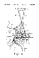
- FIG. 6 is a top perspective view of a lower back during surgery showing a pair of keyhole rod benders in the criss-cross bending procedure.
- FIG. 2 a spine 20 is undergoing rod implant back surgery.
- the patient is lying on his stomach.
- the sacrum 21 and iliac crests 22, 23 are used to support the rods R 1 , R 2 in a known manner.
- a hidden bone screw 24 in the lumbar L5 supports the clamp C 2 .
- a clamp C 1 is secured in a similar manner to lumbar L4.
- Lumbar L3 lies above lumbar L4.
- a pair of keyhole benders B L , B R are performing in situ bending of the rod R 1 in the coronal (horizontal) plane.
- Spreading forces F 1 , F 2 are applied by the surgeon located at position Y to keyhole benders B L , B R to more precisely align rod R 1 with lumbar L3.
- the keyhole bender B R is used by the right hand of the surgeon in the procedure shown in FIG. 2.
- the handle 11 is flat, and the finish 12 is 80 grit on 304ss.
- the working ends 13, 14 are made of 440A hardenable stainless steel. A design choice would include a tool made completely out of one piece of 440A hardenable stainless steel.
- the rod slots 15, 16 are provided in the working ends 13, 14. The edges E help the surgeon to resist rotational torques on the handle 11.
- keyhole bender B R is as follows:
- FIG. 4 is shown the taper of handle 11 from a center width W7 of 3/4" on the top surface 120 down to a working end width W6 of 3/8". This shape offers the surgeon a tapered grip at G 1 or G 2 if he desires.
- FIG. 5(a) the critical keyhole 50 is shown in rod slot 16.
- a boring drill has been used to create the keyhole 50 by boring two off axis bores in rod slot 16.
- the central axis of rod slot 16 is shown as C--C in FIGS. 5(a), 5(b). Width W5 is 0.270 inch.
- the bender B R is drilled along axis D--D and axis E--E. Off axis D--D and E--E are each 3° (as shown by angle ⁇ ) off axis from central axis C--C.
- the axes C--C, D--D, E--E are all co-planar.
- Central axis C--C is at a 90° angle to the working end 14 axis W--W and co-planar therewith.
- the angle ⁇ 2 allows a comfortable hand operating distance d 10 at the handle ends 14, 140 of the benders B L , B R .
- the working ends 13, 130 are bending rod R 1 in the opposite direction as that shown in FIG. 2.
Abstract
A pair of surgical in situ rod benders having keyhole notches to prevent slipping off the rod while in use. The in situ benders also have a 20° offset angle to allow a criss-cross pushing tension during bending. A flat tapered handle helps the surgeon counter rotational torques during bending.
Description
The present invention relates to improvements to in situ rod benders used in back surgery.
The human spine normally has contours in the sagital (vertical) plane. A deformed spine may have contours in the coronal (horizontal) plane and/or the axial (rotational) plane. It has become a common surgical practice to insert one or two rods in the spine to straighten a deformed spine. Bone screws are placed in the pedacles of the backbone to secure the rods. The rods are pre-bent to the approximate corrective angles as taught by U.S. Pat. No. 5,113,685 (1992) to Asher et al. The rods are then inserted into the backbone and secured with clamps to the bone screws.
At this stage in the surgical procedure there needs to be made in situ adjustment bends to the rod(s). Space to access the rod(s) is at a premium. The clamps are usually spaced about four inches apart. The lamina (ridges) of the backbone complicate access to the rod(s). The rod(s) are full of blood and are slippery.
The rods are usually 1/4 inch in diameter and constructed of stainless steel. In situ bending also requires moving the rib cage and large portions of body mass. It takes all the strength of a surgeon to bend the rods even with the use of fifteen inch bending tools. If the bending tools slip off the rod during the in situ bending procedure, then injury to the patient can occur.
Known in the art is the Isola® In Situ Bender Model 2060-30 manufactured by Acromed. FIG. 1 shows the right hand Model 2060-30 bender 1. It is a stainless steel instrument having a tubular handle 2. A portion of the handle 2 has knurls 3. The working ends 4,6 are offset an angle θ1 of about 10°. Working end 4 has rod slot 5. W2 is 1/4 inch to accommodate a 1/4 inch stainless steel rod. A rod slot (not shown) on working end 6 has a width of 3/16 inch for a 3/16 inch rod. Each rod slot has a single central bore (B--B for rod slot 5).
In operation to grasp a rod (not shown) the rod slot 5 is placed on the rod, and a left bender (not shown) is placed at a desired point on the same rod. The surgeon then pushes or pulls the benders to obtain the desired bend.
There are no means to secure,the rod inside the rod slot 5 during the bending procedure. Thus, the rod is prone to slip out of the rod slot 5 during the bending procedure. This can injure a patient.
The present invention adds two additional bores besides the central axis bore B--B. Each additional bore is at about a 3° angle off axis to B--B. This creates a keyhole notch which helps secure the rod during the bending operation. Additionally a new flat handle is provided rather than a tubular handle. This flat handle helps the surgeon to overcome rotational forces on the handle. The angle θ1 of about 10° is also increased to about 20°. This permits a criss-crossing of the benders. The surgeon now has the option of squeezing or pushing the benders together rather than pulling them apart.
The dimensions of the prior art shown in FIG. 1 are as follows:
θ1 =10°
W2 =1/4"
W1 =7/16"
d1 =131/2"
d2 =3/4"
The primary object of the present invention is to provide a keyhole in the rod slot of benders to secure a rod during the bending procedure of the rod.
Another object of the present invention is to provide flat, tapered handles on a rod bender to help counter rotational torque.
Another object of the present invention is to provide approximately a 20° offset on the working ends of a rod bender to allow criss-crossing the benders, thereby enabling pushing the handle ends together.
Other objects of this invention will appear from the following description and appended claims, referenced being had to the accompanying drawings forming a part of this specification wherein like reference characters designate corresponding parts in the several views.
The keyhole rod bender improves upon the prior art for in situ benders by adding two additional center bores at 3° off axis in the rod slot. The result is a small keyhole shape in the bottom of the rod slot. These semi-circular seats form an area of contact with the rod in the shape of a frustum of a cone. It is understood that each bore is the same size as the rod. When the benders are under tension while grasping a rod, the keyhole helps to prevent the rod from slipping out of the rod slot. Surgeons are not mechanics who use tools eight hours a day. The keyhole rod bender helps to reduce the odds of a dangerous slip off the rod.
To further help the surgeon the rod handle is flat and tapered having an 80 grit non slip finish. This puts the edges of the rod into the flesh of the surgeon's hands. These edges help the surgeon to resist the rotational forces which are created in the rod during the bending procedure.
Another advantage for the surgeon is the increased offset angle to 20° at the working ends. This allows the surgeon to criss-cross the benders and push them together or squeeze them with his fists. When working at waist level to exert almost full arm strength on the benders, it is easier to push together rather than pull apart.
Each of the above improvements enhance the surgeon's precision and the patient's safety. The combination of these improvements provide the surgeon with a major advancement in surgical techniques.
FIG. 1 (Prior art) is a side plan view of an Acromed Model 2060-30 in situ bender.
FIG. 2 is a top perspective view of a lower back during surgery showing a pair of in situ benders in operation.
FIG. 3 is a side plan view of the keyhole rod bender.
FIG. 4 is a top plan view of the keyhole rod bender of FIG. 3.
FIG. 5(a) is a side plan view of the keyhole rod slot of FIGS. 3,4.
FIG. 5(b) is a top plan view of the keyhole rod slot of FIG. 5(a).
FIG. 6 is a top perspective view of a lower back during surgery showing a pair of keyhole rod benders in the criss-cross bending procedure.
Before explaining the disclosed embodiment of the present invention in detail, it is to be understood that the invention is not limited in its application to the details of the particular arrangement shown, since the invention is capable of other embodiments. Also, the terminology used herein is for the purpose of description and not of limitation.
Referring now to FIG. 2 a spine 20 is undergoing rod implant back surgery. The patient is lying on his stomach. The sacrum 21 and iliac crests 22, 23 are used to support the rods R1, R2 in a known manner. A hidden bone screw 24 in the lumbar L5 supports the clamp C2. A clamp C1 is secured in a similar manner to lumbar L4. Lumbar L3 lies above lumbar L4.
A pair of keyhole benders BL, BR are performing in situ bending of the rod R1 in the coronal (horizontal) plane. Spreading forces F1, F2 are applied by the surgeon located at position Y to keyhole benders BL, BR to more precisely align rod R1 with lumbar L3.
Referring next to FIG. 3 the keyhole bender BR is used by the right hand of the surgeon in the procedure shown in FIG. 2. The handle 11 is flat, and the finish 12 is 80 grit on 304ss. The working ends 13, 14 are made of 440A hardenable stainless steel. A design choice would include a tool made completely out of one piece of 440A hardenable stainless steel. The rod slots 15, 16 are provided in the working ends 13, 14. The edges E help the surgeon to resist rotational torques on the handle 11.
Other dimensions of keyhole bender BR are as follows:
θ2 =20° ±2°
W3 =0.260 inch
W4 =3/8"
d3 =131/2"
d4 =3/4"
In FIG. 4 is shown the taper of handle 11 from a center width W7 of 3/4" on the top surface 120 down to a working end width W6 of 3/8". This shape offers the surgeon a tapered grip at G1 or G2 if he desires.
In FIG. 5(a) the critical keyhole 50 is shown in rod slot 16. A boring drill has been used to create the keyhole 50 by boring two off axis bores in rod slot 16.
The central axis of rod slot 16 is shown as C--C in FIGS. 5(a), 5(b). Width W5 is 0.270 inch. To produce the opposing notches N1, N2 and the opposing notches N3, N4, the bender BR is drilled along axis D--D and axis E--E. Off axis D--D and E--E are each 3° (as shown by angle α) off axis from central axis C--C. The axes C--C, D--D, E--E are all co-planar. Central axis C--C is at a 90° angle to the working end 14 axis W--W and co-planar therewith.
In operation during in situ bending the rod lodges at opposing notches N1, N2 or N3, N4 while the rod is under strain. It can be seen that these notches are only 0.005 inch deep at the surface. This equates to one half the difference between W5-W3. There exists about 1000 lbs. of indentation pressure at the notches. It is important to provide a shape of the notch as a frustum of a cone (indicated by dotted lines in FIG. 5(b)) in order to resist indenting the rod. This holding effect of the keyhole 50 by means of opposing notches N1, N2 /N3, N4 greatly assists the surgeon to reduce the risk of accidentally pulling the rod out of the rod slot 16.
Referring last to FIG. 6 the same surgeon as shown in FIG. 2 is now using a criss-cross method of pushing keyhole benders BL, BR together. The angle θ2 allows a comfortable hand operating distance d10 at the handle ends 14, 140 of the benders BL, BR. The working ends 13, 130 are bending rod R1 in the opposite direction as that shown in FIG. 2.
For the surgeon operating at waist level it is easier for him to exert pushing forces F10, F20 instead of pulling forces F1, F2 as shown in FIG. 2.
Claims (18)
1. A first and second rod bender capable of plastically deforming a rod by movement relative to each other under an influence of force manually applied to end portions of said first and second rod benders, said first and second rod benders each comprising:
a handle having a center;
a working end at one end of said handle;
said working end further comprising a working end central axis;
said working end further comprising a rod slot having a bottom, a rod slot central axis, and a diameter; and
said rod slot further comprising a keyhole hollow at the bottom formed substantially by a pair of offset bores, whereby the rod is held in a substantially static manner by opposing notches in the keyhole hollow.
2. The rod benders of claim 1 wherein said offset bores further comprise a 2° to 5° offset relative to the rod slot central axis and co-planar therewith.
3. The rod benders of claim 2 wherein said offset bores further comprise a diameter of about 0.005 inch wider than the rod slot diameter.
4. The rod benders of claim 1 wherein said rod slot central axis further comprises a 90° offset to said working end central axis.
5. The rod benders of claim 1 wherein said working end further comprises substantially a 20° offset to said handle.
6. The rod benders of claim 1 wherein said handle further comprises a flat shape having edges.
7. The rod benders of claim 6 wherein said handle further comprises a taper extending from a widest point at the center of the handle and narrowing to the working end.
8. The rod benders of claim 7 wherein said handle further comprises an 80 grit finish.
9. The rod benders of claim 1 wherein said handle is substantially 131/2" long and the working end is substantially 3/4" long.
10. The rod benders of claim 1 further comprising a second working end located at an opposite end of the handle from said working end.
11. A first and second surgical rod bender capable of plastically deforming a surgically implanted rod in situ by movement relative to each other under an influence of force manually applied to end portions of said first and second rod benders, said first and second rod benders each comprising:
a shaft having a central handle portion;
a working end at each end of the shaft;
said working ends each further comprising a rod slot having a bottom, a rod slot central axis, and a diameter; and
said rod slot further comprising a keyhole hollow at the bottom formed substantially by a pair of bores 2° to 5° offset relative to the rod slot central axis, whereby the rod is held in a substantially static manner by opposing notches in the keyhole hollow.
12. The rod benders of claim 11 wherein said working ends further comprise a 20° offset to said shaft.
13. The rod benders of claim 11 wherein said offset bores further comprise a diameter of about 0.005 inch wider than the rod slot diameter.
14. The rod benders of claim 11 wherein said central handle portion further comprises a flat shape having edges.
15. The rod benders of claim 14 wherein said central handle portion further comprises a taper extending from a widest point at a midpoint of the central handle portion and narrowing to each working end.
16. A pair of rod benders each comprising:
a shank;
a working end at one end of the shank;
said working end further comprising a rod slot having a rod slot central axis 90° offset to the working end;
said rod slot further comprising a diameter to accommodate a rod, and a bottom; and
said rod slot bottom further comprising a keyhole hollow formed substantially by a pair of offset bores, whereby the rod is held in a substantially static manner by opposing notches in the keyhole hollow.
17. The rod benders of claim 16 wherein said offset bores further comprise a 2° to 5° offset relative to the rod slot central axis and co-planar therewith.
18. The rod benders of claim 17 wherein said offset bores further comprise a diameter of about 0.005 inch wider than the rod slot diameter.
Priority Applications (1)
| Application Number | Priority Date | Filing Date | Title |
|---|---|---|---|
| US08/098,804 US5389099A (en) | 1993-07-28 | 1993-07-28 | Keyhole rod bender |
Applications Claiming Priority (1)
| Application Number | Priority Date | Filing Date | Title |
|---|---|---|---|
| US08/098,804 US5389099A (en) | 1993-07-28 | 1993-07-28 | Keyhole rod bender |
Publications (1)
| Publication Number | Publication Date |
|---|---|
| US5389099A true US5389099A (en) | 1995-02-14 |
Family
ID=22270975
Family Applications (1)
| Application Number | Title | Priority Date | Filing Date |
|---|---|---|---|
| US08/098,804 Expired - Fee Related US5389099A (en) | 1993-07-28 | 1993-07-28 | Keyhole rod bender |
Country Status (1)
| Country | Link |
|---|---|
| US (1) | US5389099A (en) |
Cited By (42)
| Publication number | Priority date | Publication date | Assignee | Title |
|---|---|---|---|---|
| WO1996029016A1 (en) * | 1995-03-23 | 1996-09-26 | Lutz Biedermann | Device for spinal column fixation |
| US5564302A (en) * | 1995-07-11 | 1996-10-15 | Watrous; Willis G. | Orthopedic bone plate bending irons |
| US5591165A (en) * | 1992-11-09 | 1997-01-07 | Sofamor, S.N.C. | Apparatus and method for spinal fixation and correction of spinal deformities |
| US5651283A (en) * | 1995-11-14 | 1997-07-29 | Terray Corporation | Bone plate shaping device |
| US5910141A (en) * | 1997-02-12 | 1999-06-08 | Sdgi Holdings, Inc. | Rod introduction apparatus |
| US5944720A (en) * | 1998-03-25 | 1999-08-31 | Lipton; Glenn E | Posterior spinal fixation system |
| US6240816B1 (en) * | 1998-12-14 | 2001-06-05 | Hilti Aktiengesellschaft | Depth stop for a hand-held screw driving tool |
| US6440133B1 (en) | 2001-07-03 | 2002-08-27 | Sdgi Holdings, Inc. | Rod reducer instruments and methods |
| US20020133155A1 (en) * | 2000-02-25 | 2002-09-19 | Ferree Bret A. | Cross-coupled vertebral stabilizers incorporating spinal motion restriction |
| US20040144149A1 (en) * | 2002-05-02 | 2004-07-29 | Walter Strippgen | Non-marring spinal rod curving instrument and method for using same |
| US20050192587A1 (en) * | 2004-02-27 | 2005-09-01 | Lim Roy K. | Rod reducer |
| US20060036254A1 (en) * | 2004-08-10 | 2006-02-16 | Roy Lim | Reducing instrument for spinal surgery |
| US20060166534A1 (en) * | 2005-01-26 | 2006-07-27 | Brumfield David L | Reducing instrument for spinal surgery |
| US20060264973A1 (en) * | 2005-05-23 | 2006-11-23 | Custom Spine, Inc. | Orthopedic implant bender |
| US20070270867A1 (en) * | 2006-04-11 | 2007-11-22 | Sdgi Holdings, Inc. | Multi-directional rod reducer instrument and method |
| US20080294165A1 (en) * | 2006-05-26 | 2008-11-27 | Mark Richard Cunliffe | Combination bone fixation device and bending tool |
| US20110245871A1 (en) * | 2010-04-06 | 2011-10-06 | Williams Lytton A | Crosslink element and bender for spine surgery procedures |
| US8298242B2 (en) | 2010-04-30 | 2012-10-30 | Warsaw Orthopedic, Inc. | Systems, devices and methods for bending an elongate member |
| FR2975583A1 (en) * | 2011-05-27 | 2012-11-30 | Iceram | Instrument twist bar for use in surgical unit at time of intervention of spinal column, has right twist part, and left twist bar comprising handle, where right and left twist bars are held in hands |
| JP2013530017A (en) * | 2010-06-28 | 2013-07-25 | ケー2エム, インコーポレイテッド | Spine stabilization system |
| US8607603B2 (en) | 2010-04-30 | 2013-12-17 | Warsaw Orthopedic, Inc. | Systems, devices and methods for multi-dimensional bending of an elongate member |
| US8668699B2 (en) | 2005-04-14 | 2014-03-11 | Warsaw Orthopedic, Inc. | Multi-function orthopedic instrument |
| US9003859B2 (en) | 2011-04-01 | 2015-04-14 | University of Alaska Anchorage | Bending instrument and methods of using same |
| US20150157363A1 (en) * | 2013-12-06 | 2015-06-11 | K2M, Inc. | Spinal stabilization system including shaped spinal rod |
| US9421596B2 (en) | 2014-04-16 | 2016-08-23 | University of Alaska Anchorage | Bending instrument and methods of using same |
| US20170087614A1 (en) * | 2015-09-29 | 2017-03-30 | Trimed, Inc. | System, including a bending bar and a bending cage, for bending a plate in a plane of the plate |
| US9636181B2 (en) | 2008-04-04 | 2017-05-02 | Nuvasive, Inc. | Systems, devices, and methods for designing and forming a surgical implant |
| US20170281252A1 (en) * | 2016-03-31 | 2017-10-05 | K2M, Inc. | Surgical rod bender |
| US9839463B2 (en) | 2012-09-06 | 2017-12-12 | Stryker European Holdings I, Llc | Instrument for use in bending surgical devices |
| US9848922B2 (en) | 2013-10-09 | 2017-12-26 | Nuvasive, Inc. | Systems and methods for performing spine surgery |
| US9913669B1 (en) | 2014-10-17 | 2018-03-13 | Nuvasive, Inc. | Systems and methods for performing spine surgery |
| US10085780B2 (en) | 2006-05-26 | 2018-10-02 | Mark Richard Cunliffe | Bone fixation device |
| US10198970B2 (en) | 2014-07-14 | 2019-02-05 | K2M, Inc. | Growing spine model |
| US10405908B2 (en) | 2014-12-18 | 2019-09-10 | Warsaw Orthopedic, Inc. | Apparatus and method for forming support device for effecting orthopedic stabilization |
| US10882096B2 (en) * | 2016-11-22 | 2021-01-05 | Brian Patrick HOLMSTOCK | Methods and apparatuses for mechanically opening and closing one or more longitudinal seams |
| US11013546B2 (en) | 2019-03-13 | 2021-05-25 | Medos International Sarl | Rod bender |
| US11207132B2 (en) | 2012-03-12 | 2021-12-28 | Nuvasive, Inc. | Systems and methods for performing spinal surgery |
| US11291477B1 (en) | 2021-05-04 | 2022-04-05 | Warsaw Orthopedic, Inc. | Dorsal adjusting implant and methods of use |
| US11432848B1 (en) | 2021-05-12 | 2022-09-06 | Warsaw Orthopedic, Inc. | Top loading quick lock construct |
| US11576727B2 (en) | 2016-03-02 | 2023-02-14 | Nuvasive, Inc. | Systems and methods for spinal correction surgical planning |
| US11712270B2 (en) | 2021-05-17 | 2023-08-01 | Warsaw Orthopedic, Inc. | Quick lock clamp constructs and associated methods |
| RU2810365C1 (en) * | 2023-04-28 | 2023-12-27 | Общество с ограниченной ответственностью "КОНМЕТ" | Tool for bending bars during transpedicular fixation |
Citations (10)
| Publication number | Priority date | Publication date | Assignee | Title |
|---|---|---|---|---|
| US2737835A (en) * | 1951-12-12 | 1956-03-13 | James R Herz | Tool for bending plates in bone surgery |
| US2800818A (en) * | 1955-03-03 | 1957-07-30 | Charles O Larson | Slotted manual bending tool |
| US3680834A (en) * | 1970-11-16 | 1972-08-01 | Wilbur Holloway | Pry bar and nail puller |
| US3819221A (en) * | 1973-01-09 | 1974-06-25 | Connor L O | Automobile door button-operating implement |
| US3866458A (en) * | 1973-11-12 | 1975-02-18 | Richard F Wagner | Bender for contouring surgical implants |
| US3965720A (en) * | 1975-07-28 | 1976-06-29 | Westinghouse Electric Corporation | Hinge adjustment tool |
| US4034595A (en) * | 1975-11-19 | 1977-07-12 | Smith Glen R | Sheet metal working tool |
| US4444228A (en) * | 1982-07-16 | 1984-04-24 | John Demirjian | Wire unwrapping tool |
| US4917154A (en) * | 1989-02-10 | 1990-04-17 | Roberson Sr Rhubert B | Fencewrench |
| US5113685A (en) * | 1991-01-28 | 1992-05-19 | Acromed Corporation | Apparatus for contouring spine plates and/or rods |
-
1993
- 1993-07-28 US US08/098,804 patent/US5389099A/en not_active Expired - Fee Related
Patent Citations (10)
| Publication number | Priority date | Publication date | Assignee | Title |
|---|---|---|---|---|
| US2737835A (en) * | 1951-12-12 | 1956-03-13 | James R Herz | Tool for bending plates in bone surgery |
| US2800818A (en) * | 1955-03-03 | 1957-07-30 | Charles O Larson | Slotted manual bending tool |
| US3680834A (en) * | 1970-11-16 | 1972-08-01 | Wilbur Holloway | Pry bar and nail puller |
| US3819221A (en) * | 1973-01-09 | 1974-06-25 | Connor L O | Automobile door button-operating implement |
| US3866458A (en) * | 1973-11-12 | 1975-02-18 | Richard F Wagner | Bender for contouring surgical implants |
| US3965720A (en) * | 1975-07-28 | 1976-06-29 | Westinghouse Electric Corporation | Hinge adjustment tool |
| US4034595A (en) * | 1975-11-19 | 1977-07-12 | Smith Glen R | Sheet metal working tool |
| US4444228A (en) * | 1982-07-16 | 1984-04-24 | John Demirjian | Wire unwrapping tool |
| US4917154A (en) * | 1989-02-10 | 1990-04-17 | Roberson Sr Rhubert B | Fencewrench |
| US5113685A (en) * | 1991-01-28 | 1992-05-19 | Acromed Corporation | Apparatus for contouring spine plates and/or rods |
Cited By (73)
| Publication number | Priority date | Publication date | Assignee | Title |
|---|---|---|---|---|
| US5591165A (en) * | 1992-11-09 | 1997-01-07 | Sofamor, S.N.C. | Apparatus and method for spinal fixation and correction of spinal deformities |
| WO1996029016A1 (en) * | 1995-03-23 | 1996-09-26 | Lutz Biedermann | Device for spinal column fixation |
| US5564302A (en) * | 1995-07-11 | 1996-10-15 | Watrous; Willis G. | Orthopedic bone plate bending irons |
| US5651283A (en) * | 1995-11-14 | 1997-07-29 | Terray Corporation | Bone plate shaping device |
| US5910141A (en) * | 1997-02-12 | 1999-06-08 | Sdgi Holdings, Inc. | Rod introduction apparatus |
| USRE43526E1 (en) * | 1997-02-12 | 2012-07-17 | Warsaw Orthopedic, Inc. | Rod introduction apparatus |
| US5944720A (en) * | 1998-03-25 | 1999-08-31 | Lipton; Glenn E | Posterior spinal fixation system |
| US6240816B1 (en) * | 1998-12-14 | 2001-06-05 | Hilti Aktiengesellschaft | Depth stop for a hand-held screw driving tool |
| US20070179503A1 (en) * | 2000-02-25 | 2007-08-02 | Ferree Bret A | Cross-coupled vertebral stabilizers incorporating spinal motion restriction |
| US20020133155A1 (en) * | 2000-02-25 | 2002-09-19 | Ferree Bret A. | Cross-coupled vertebral stabilizers incorporating spinal motion restriction |
| US6790209B2 (en) | 2001-07-03 | 2004-09-14 | Sdgi Holdings, Inc. | Rod reducer instruments and methods |
| USRE44296E1 (en) * | 2001-07-03 | 2013-06-11 | Warsaw Orthopedic, Inc. | Rod reducer instruments and methods |
| US6440133B1 (en) | 2001-07-03 | 2002-08-27 | Sdgi Holdings, Inc. | Rod reducer instruments and methods |
| USRE44813E1 (en) * | 2001-07-03 | 2014-03-18 | Warsaw Orthopedic, Inc. | Rod reducer instruments and methods |
| US20040144149A1 (en) * | 2002-05-02 | 2004-07-29 | Walter Strippgen | Non-marring spinal rod curving instrument and method for using same |
| US7922724B2 (en) | 2004-02-27 | 2011-04-12 | Warsaw Orthopedic, Inc. | Rod reducer |
| US7611517B2 (en) | 2004-02-27 | 2009-11-03 | Warsaw Orthopedic, Inc. | Rod reducer |
| US20060276798A1 (en) * | 2004-02-27 | 2006-12-07 | Sdgi Holdings, Inc. | Rod reducer |
| US20050192587A1 (en) * | 2004-02-27 | 2005-09-01 | Lim Roy K. | Rod reducer |
| US20060036254A1 (en) * | 2004-08-10 | 2006-02-16 | Roy Lim | Reducing instrument for spinal surgery |
| US7462182B2 (en) | 2004-08-10 | 2008-12-09 | Warsaw Orthopedic, Inc. | Reducing instrument for spinal surgery |
| US8105329B2 (en) | 2005-01-26 | 2012-01-31 | Warsaw Orthopedic, Inc. | Reducing instrument for spinal surgery |
| US20060166535A1 (en) * | 2005-01-26 | 2006-07-27 | Brumfield David L | Reducing instrument for spinal surgery |
| US7625376B2 (en) | 2005-01-26 | 2009-12-01 | Warsaw Orthopedic, Inc. | Reducing instrument for spinal surgery |
| US7744598B2 (en) | 2005-01-26 | 2010-06-29 | Warsaw Orthopedic, Inc. | Reducing instrument for spinal surgery |
| US20100280560A1 (en) * | 2005-01-26 | 2010-11-04 | Warsaw Orthopedic, Inc. | Reducing Instrument for Spinal Surgery |
| US20060166534A1 (en) * | 2005-01-26 | 2006-07-27 | Brumfield David L | Reducing instrument for spinal surgery |
| US8668699B2 (en) | 2005-04-14 | 2014-03-11 | Warsaw Orthopedic, Inc. | Multi-function orthopedic instrument |
| US7488331B2 (en) | 2005-05-23 | 2009-02-10 | Custon Spine, Inc. | Orthopedic implant bender |
| US20060264973A1 (en) * | 2005-05-23 | 2006-11-23 | Custom Spine, Inc. | Orthopedic implant bender |
| US20070270867A1 (en) * | 2006-04-11 | 2007-11-22 | Sdgi Holdings, Inc. | Multi-directional rod reducer instrument and method |
| US7927334B2 (en) | 2006-04-11 | 2011-04-19 | Warsaw Orthopedic, Inc. | Multi-directional rod reducer instrument and method |
| US10932835B2 (en) | 2006-05-26 | 2021-03-02 | Mark Richard Cunliffe | Bone fixation device |
| US8337506B2 (en) * | 2006-05-26 | 2012-12-25 | Mark Richard Cunliffe | Combination bone fixation device and bending tool |
| US20080294165A1 (en) * | 2006-05-26 | 2008-11-27 | Mark Richard Cunliffe | Combination bone fixation device and bending tool |
| US10085780B2 (en) | 2006-05-26 | 2018-10-02 | Mark Richard Cunliffe | Bone fixation device |
| US11453041B2 (en) | 2008-04-04 | 2022-09-27 | Nuvasive, Inc | Systems, devices, and methods for designing and forming a surgical implant |
| US10500630B2 (en) | 2008-04-04 | 2019-12-10 | Nuvasive, Inc. | Systems, devices, and methods for designing and forming a surgical implant |
| US9636181B2 (en) | 2008-04-04 | 2017-05-02 | Nuvasive, Inc. | Systems, devices, and methods for designing and forming a surgical implant |
| US20110245871A1 (en) * | 2010-04-06 | 2011-10-06 | Williams Lytton A | Crosslink element and bender for spine surgery procedures |
| US8607603B2 (en) | 2010-04-30 | 2013-12-17 | Warsaw Orthopedic, Inc. | Systems, devices and methods for multi-dimensional bending of an elongate member |
| US8298242B2 (en) | 2010-04-30 | 2012-10-30 | Warsaw Orthopedic, Inc. | Systems, devices and methods for bending an elongate member |
| US9295494B2 (en) | 2010-06-28 | 2016-03-29 | K2M, Inc. | Spine stabilization system |
| JP2013530017A (en) * | 2010-06-28 | 2013-07-25 | ケー2エム, インコーポレイテッド | Spine stabilization system |
| US9820779B2 (en) | 2010-06-28 | 2017-11-21 | K2M, Inc. | Spinal stabilization system |
| US9003859B2 (en) | 2011-04-01 | 2015-04-14 | University of Alaska Anchorage | Bending instrument and methods of using same |
| FR2975583A1 (en) * | 2011-05-27 | 2012-11-30 | Iceram | Instrument twist bar for use in surgical unit at time of intervention of spinal column, has right twist part, and left twist bar comprising handle, where right and left twist bars are held in hands |
| US11207132B2 (en) | 2012-03-12 | 2021-12-28 | Nuvasive, Inc. | Systems and methods for performing spinal surgery |
| US9839463B2 (en) | 2012-09-06 | 2017-12-12 | Stryker European Holdings I, Llc | Instrument for use in bending surgical devices |
| US9848922B2 (en) | 2013-10-09 | 2017-12-26 | Nuvasive, Inc. | Systems and methods for performing spine surgery |
| US9421038B2 (en) * | 2013-12-06 | 2016-08-23 | K2M, Inc. | Spinal stabilization system including shaped spinal rod |
| US20150157363A1 (en) * | 2013-12-06 | 2015-06-11 | K2M, Inc. | Spinal stabilization system including shaped spinal rod |
| US9421596B2 (en) | 2014-04-16 | 2016-08-23 | University of Alaska Anchorage | Bending instrument and methods of using same |
| US10198970B2 (en) | 2014-07-14 | 2019-02-05 | K2M, Inc. | Growing spine model |
| US9913669B1 (en) | 2014-10-17 | 2018-03-13 | Nuvasive, Inc. | Systems and methods for performing spine surgery |
| US11213326B2 (en) | 2014-10-17 | 2022-01-04 | Nuvasive, Inc. | Systems and methods for performing spine surgery |
| US10433893B1 (en) | 2014-10-17 | 2019-10-08 | Nuvasive, Inc. | Systems and methods for performing spine surgery |
| US10485589B2 (en) | 2014-10-17 | 2019-11-26 | Nuvasive, Inc. | Systems and methods for performing spine surgery |
| US10405908B2 (en) | 2014-12-18 | 2019-09-10 | Warsaw Orthopedic, Inc. | Apparatus and method for forming support device for effecting orthopedic stabilization |
| US20170087614A1 (en) * | 2015-09-29 | 2017-03-30 | Trimed, Inc. | System, including a bending bar and a bending cage, for bending a plate in a plane of the plate |
| US9956599B2 (en) * | 2015-09-29 | 2018-05-01 | Trimed, Inc. | System, including a bending bar and a bending cage, for bending a plate in a plane of the plate |
| US11903655B2 (en) | 2016-03-02 | 2024-02-20 | Nuvasive Inc. | Systems and methods for spinal correction surgical planning |
| US11576727B2 (en) | 2016-03-02 | 2023-02-14 | Nuvasive, Inc. | Systems and methods for spinal correction surgical planning |
| US20170281252A1 (en) * | 2016-03-31 | 2017-10-05 | K2M, Inc. | Surgical rod bender |
| US10610277B2 (en) * | 2016-03-31 | 2020-04-07 | K2M, Inc. | Surgical rod bender |
| US11737803B2 (en) * | 2016-03-31 | 2023-08-29 | K2M, Inc. | Surgical rod bender |
| US10882096B2 (en) * | 2016-11-22 | 2021-01-05 | Brian Patrick HOLMSTOCK | Methods and apparatuses for mechanically opening and closing one or more longitudinal seams |
| US11013546B2 (en) | 2019-03-13 | 2021-05-25 | Medos International Sarl | Rod bender |
| US11291477B1 (en) | 2021-05-04 | 2022-04-05 | Warsaw Orthopedic, Inc. | Dorsal adjusting implant and methods of use |
| US11432848B1 (en) | 2021-05-12 | 2022-09-06 | Warsaw Orthopedic, Inc. | Top loading quick lock construct |
| US11712270B2 (en) | 2021-05-17 | 2023-08-01 | Warsaw Orthopedic, Inc. | Quick lock clamp constructs and associated methods |
| US11957391B2 (en) | 2021-11-01 | 2024-04-16 | Warsaw Orthopedic, Inc. | Bone screw having an overmold of a shank |
| RU2810365C1 (en) * | 2023-04-28 | 2023-12-27 | Общество с ограниченной ответственностью "КОНМЕТ" | Tool for bending bars during transpedicular fixation |
Similar Documents
| Publication | Publication Date | Title |
|---|---|---|
| US5389099A (en) | Keyhole rod bender | |
| JP4176009B2 (en) | Surgical rod adjustment instrument and method | |
| JP6822698B2 (en) | Surgical couplers and instruments | |
| US5113685A (en) | Apparatus for contouring spine plates and/or rods | |
| US5746742A (en) | Bone plate template | |
| US8167908B2 (en) | Polyaxial transverse connector | |
| EP2177172B1 (en) | Instruments for reduction of vertebral bodies | |
| US8864767B2 (en) | Rod reducer instrument for spinal surgery | |
| US4903691A (en) | Set of surgical instruments for joining bone fragments | |
| EP2187827B1 (en) | Spinal stabilization systems with quick-connect sleeve assemblies for use in surgical procedures | |
| US8870890B2 (en) | Pronged holder for treating spinal stenosis | |
| AU621700B2 (en) | Surgical rod pusher instrument | |
| US7588588B2 (en) | System and method for stabilizing of internal structures | |
| US7416553B2 (en) | Drill guide and plate inserter | |
| US8454665B2 (en) | Multi-purpose bone plate system | |
| US5609596A (en) | Guide rod holder for manipulating surgical wires and pins | |
| US9408716B1 (en) | Percutaneous posterior spinal fusion implant construction and method | |
| WO2007016289A1 (en) | Expandable access device | |
| WO1994006362A1 (en) | Tool and method for derotating scoliotic spine | |
| JP2000501624A (en) | Apparatus for linking adjacent rods in spinal instrumentation | |
| US20040210232A1 (en) | Guide device and plate inserter | |
| EP2774564B1 (en) | Percutaneous rod inserter | |
| US10159579B1 (en) | Tubular instruments for percutaneous posterior spinal fusion systems and methods | |
| US11490930B2 (en) | Internal pelvic fixator | |
| US9744050B1 (en) | Compression and distraction system for percutaneous posterior spinal fusion |
Legal Events
| Date | Code | Title | Description |
|---|---|---|---|
| REMI | Maintenance fee reminder mailed | ||
| LAPS | Lapse for failure to pay maintenance fees | ||
| FP | Expired due to failure to pay maintenance fee |
Effective date: 19990214 |
|
| STCH | Information on status: patent discontinuation |
Free format text: PATENT EXPIRED DUE TO NONPAYMENT OF MAINTENANCE FEES UNDER 37 CFR 1.362 |