US5401421A - Energy efficient water purification system - Google Patents
Energy efficient water purification system Download PDFInfo
- Publication number
- US5401421A US5401421A US08/072,596 US7259693A US5401421A US 5401421 A US5401421 A US 5401421A US 7259693 A US7259693 A US 7259693A US 5401421 A US5401421 A US 5401421A
- Authority
- US
- United States
- Prior art keywords
- water
- feed water
- flow
- heated
- treatment
- Prior art date
- Legal status (The legal status is an assumption and is not a legal conclusion. Google has not performed a legal analysis and makes no representation as to the accuracy of the status listed.)
- Expired - Lifetime
Links
Images
Classifications
-
- B—PERFORMING OPERATIONS; TRANSPORTING
- B01—PHYSICAL OR CHEMICAL PROCESSES OR APPARATUS IN GENERAL
- B01D—SEPARATION
- B01D61/00—Processes of separation using semi-permeable membranes, e.g. dialysis, osmosis or ultrafiltration; Apparatus, accessories or auxiliary operations specially adapted therefor
- B01D61/02—Reverse osmosis; Hyperfiltration ; Nanofiltration
- B01D61/04—Feed pretreatment
-
- B—PERFORMING OPERATIONS; TRANSPORTING
- B01—PHYSICAL OR CHEMICAL PROCESSES OR APPARATUS IN GENERAL
- B01D—SEPARATION
- B01D61/00—Processes of separation using semi-permeable membranes, e.g. dialysis, osmosis or ultrafiltration; Apparatus, accessories or auxiliary operations specially adapted therefor
- B01D61/02—Reverse osmosis; Hyperfiltration ; Nanofiltration
- B01D61/025—Reverse osmosis; Hyperfiltration
-
- C—CHEMISTRY; METALLURGY
- C02—TREATMENT OF WATER, WASTE WATER, SEWAGE, OR SLUDGE
- C02F—TREATMENT OF WATER, WASTE WATER, SEWAGE, OR SLUDGE
- C02F1/00—Treatment of water, waste water, or sewage
- C02F1/02—Treatment of water, waste water, or sewage by heating
-
- B—PERFORMING OPERATIONS; TRANSPORTING
- B01—PHYSICAL OR CHEMICAL PROCESSES OR APPARATUS IN GENERAL
- B01D—SEPARATION
- B01D2311/00—Details relating to membrane separation process operations and control
- B01D2311/04—Specific process operations in the feed stream; Feed pretreatment
Definitions
- the present invention relates to an energy efficient water purification system for water treatment USING a reverse osmosis machine.
- the water is pre-treated by being caused to flow through a succession of units, consisting of a sediment filter, a water softener and carbon filters.
- the pre-treated water is then fed to the reverse osmosis machine where it is purified for its end use.
- timing devices for the pre-treatment devices of the system operate to cause each piece of equipment to go through its regeneration or flushing mode.
- the system normally causes the flow through the unit to be reversed so that the reverse flow causes the contaminants removed by the unit to be discharged from the system. After the flushing or regeneration, the unit is returned to its normal operation.
- each unit In conventional systems, the operation of each unit is automatically timed to flush during an off-peak period, by reversing the flow of the water through the piece of equipment and diverting the effluent to waste.
- the reverse osmosis machine may operate with feed water at its normal supply temperature.
- efficient operation of the reverse osmosis machine requires that the temperature of the water be heated to about 77° F., which is the optimum temperature for operation of the membranes in the reverse osmosis machine.
- the temperature of the water is normally elevated by mixing fresh unheated water with heated water in a proportion to achieve a 77° temperature at the input to the reverse osmosis machine.
- the standard practice is to mix the hot and cold water to adjust the temperature in advance of the pre-treatment units.
- the water flowing through the pre-treatment units is controlled as to its temperature to assure 77° water entering the reverse osmosis machine.
- the present invention provides a mechanism for effecting a considerable saving in energy during the regeneration period.
- the present invention provides for interrupting the temperature control of the water flowing through the units during the periods when regeneration is being effected.
- the interruption of the temperature control is preferably achieved by cutting off the flow of hot water and substituting a flow of fresh water to the pre-treatment units during regeneration.
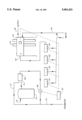
- the Figure is a schematic diagram of a water purification system embodying pre-treatment units for the water, all controlled in accordance with the present invention.
- an energy efficient water purification system including a cold water inlet 13; a hot water inlet 12 for causing a flow of feed water into the water purification system and a heater 10 to heat the flow of water from the hot water inlet 12; means to adjust the temperature of the water, in the present case a blending valve 20; a pre-treatment system comprising, for example, a sediment filter unit 31, a water softener unit 32, and carbon filter units 33 and 34; a reverse osmosis machine 40 having an inlet port 42 for receiving the flow of heated water at a given temperature to filter the water and discharge impurities therefrom; and a purified water outlet 45 for discharging the purified water from the reverse osmosis machine to the end use area.
- a pre-treatment system comprising, for example, a sediment filter unit 31, a water softener unit 32, and carbon filter units 33 and 34
- a reverse osmosis machine 40 having an inlet port 42 for receiving the flow of heated water at a given temperature to filter the water and
- the heater 10 heats the flow of water entering the water purification system through the hot water inlet 12, the hot water inlet line discharges the heated water in a hot water stream 14 to the blending valve 20 where the hot water is blended with a flow of water from the cold water inlet line 13.
- the hot water heater 10 is of the electric type.
- the blending valve 20 is controlled by a thermal sensor in the valve to maintain the temperature of the water at the critical temperature of 77° F., the thermal sensor actuates the blending valve 20 such that the heated flow of water from the hot water inlet line is increased relative to the flow of water from the cold water inlet line 13.
- the thermal sensor actuates the valve 20 to add cold water in the valve 20 where the temperature is modulated to achieve the aforesaid critical temperature. It is essential that the temperature of the water remain at 77° F. for optimal operation of the reverse osmosis machine 40.
- the heated water flowing from the valve 20 is pre-treated and, to this end, the flow from the valve 20 is directed through a three-way valve 30 to the first of a succession of pre-treatment units, namely a sediment filter 31.
- the valve 30 has one inlet port, normally open, connected to the valve 20, a second inlet port, normally closed, connected to the cold water inlet 13, and an outlet port, always open, connected to the pre-treatment system.
- the water is successively passed through the water softener 32 and the carbon filters 33 and 34 to the inlet 42 of the reverse osmosis machine 40.
- the reverse osmosis machine 40 receives the flow of hot water from the blending valve 20 to purify the water and discharge impurities therefrom in a drainage stream 44.
- the reverse osmosis machine 40 includes a membrane 43 to filter the water, discharging the purified water into a product stream through the outlet 45. Approximately 50% of the water is discharged to the drainage stream 44 and the other 50% of the water continues on into the product stream for its ultimate end use.
- Water purification systems using a reverse osmosis machine are required to purify the water for kidney dialysis machines, but are more widely used where a high degree of water purification is desirable as in hospitals, laboratories, manufacturing operations having water systems where the feed water is contaminated, odoriferous or otherwise not suitable for conventional water treatment equipment. For systems requiring a low output, the temperature control may be omitted for economic reasons.
- the pre-treatment units 31, 32, 33 and 34 must be regenerated.
- the regeneration occurs during off-peak operation and consists of a reverse flush or backwash of each unit.
- each unit operated independently of the others in accordance with its own controls to flush and backwash during a quiet period, for example during off-peak hours when no water purification operation is running.
- a normal back-flushing of the pre-treatment system may use in excess of 1000 gallons of water per regeneration, and it has been found that a considerable energy loss results by the use of water heated at 77° to achieve the backwashing. It has been found that the backwashing of the pre-treatment devices is substantially fully effective with backwashing with fresh unheated water. By eliminating the need to use heated water in flushing the pre-treatment units 31-34, a considerable saving in heat energy is achieved.
- the three-way valve 30 is connected to the fresh water inlet 13 so as to enable the valve to be operated to bypass the heating system including the hot water inlet 12, the heater 10 and the blending valve 20.
- a control box 37 is coupled to the valve and the pre-treatment units 31-34 so that all of the devices are flushed with cold water rather than heated water.
- the box also includes a connection to the reverse osmosis machine 40 to disable the machine during the regeneration and avoid inadvertent start-up.
- the flushing water is discharged to a drain line 38.
- a conventional water purification system which consists of fluid inlets for causing a flow of water, a reverse osmosis machine for receiving the flow of water and having a membrane operable at a first given temperature to purify the water and discharge impurities therefrom in a discharge stream, and an outlet receiving the purified water from the reverse osmosis machine, and a valve to control the temperature of the water entering the reverse osmosis machine at the first given temperature.
- the improved apparatus for conserving energy comprises an unheated fluid inlet to introduce fresh water through the pre-treatment units during their regeneration cycles.
Abstract
Description
Claims (8)
Priority Applications (1)
| Application Number | Priority Date | Filing Date | Title |
|---|---|---|---|
| US08/072,596 US5401421A (en) | 1993-06-03 | 1993-06-03 | Energy efficient water purification system |
Applications Claiming Priority (1)
| Application Number | Priority Date | Filing Date | Title |
|---|---|---|---|
| US08/072,596 US5401421A (en) | 1993-06-03 | 1993-06-03 | Energy efficient water purification system |
Publications (1)
| Publication Number | Publication Date |
|---|---|
| US5401421A true US5401421A (en) | 1995-03-28 |
Family
ID=22108626
Family Applications (1)
| Application Number | Title | Priority Date | Filing Date |
|---|---|---|---|
| US08/072,596 Expired - Lifetime US5401421A (en) | 1993-06-03 | 1993-06-03 | Energy efficient water purification system |
Country Status (1)
| Country | Link |
|---|---|
| US (1) | US5401421A (en) |
Cited By (10)
| Publication number | Priority date | Publication date | Assignee | Title |
|---|---|---|---|---|
| WO1996025214A1 (en) * | 1995-02-13 | 1996-08-22 | Aksys, Ltd. | Modular home dialysis system |
| US6228255B1 (en) | 1998-07-24 | 2001-05-08 | Dialysis Systems, Inc. | Portable water treatment facility |
| US6251279B1 (en) | 1999-12-09 | 2001-06-26 | Dialysis Systems, Inc. | Heat disinfection of a water supply |
| US20030089651A1 (en) * | 2001-10-18 | 2003-05-15 | Peterson Robert R. | Water system for bacteria control |
| US20040109788A1 (en) * | 2002-07-12 | 2004-06-10 | Lixiong Li | Apparatus and method for continuous depyrogenation and production of sterile water for injection |
| US20050121388A1 (en) * | 2002-10-23 | 2005-06-09 | Usfilter Corporation | Production of water for injection using reverse osmosis |
| US20090134080A1 (en) * | 2005-10-20 | 2009-05-28 | Marcus John Fabig | Purified Water Production and Distribution System |
| EP2165635A2 (en) | 2008-09-23 | 2010-03-24 | MEIKO Maschinenbau GmbH & Co. KG | Dish washers with low temperature rinsing |
| CN104045199A (en) * | 2014-05-27 | 2014-09-17 | 鲁同新 | Method for increasing efficiency of R/O membrane by using PTF instant heater |
| US10683213B2 (en) * | 2017-06-13 | 2020-06-16 | Marcos VIELMA | Water quality detection and diversion device, system, and method |
Citations (9)
| Publication number | Priority date | Publication date | Assignee | Title |
|---|---|---|---|---|
| US2332995A (en) * | 1939-06-22 | 1943-10-26 | Crosweller & Co Ltd W | Thermostatic fluid mixing device |
| US3352779A (en) * | 1965-10-23 | 1967-11-14 | Sweden Freezer Mfg Co | Hemodialysis system |
| CA903678A (en) * | 1972-06-27 | B. Bowman Donald | Hemodialysis method and equipment | |
| US4617115A (en) * | 1980-10-06 | 1986-10-14 | Hospal Industrie | Artificial kidney with disposable dialysis liquid circuit |
| US4804474A (en) * | 1987-12-10 | 1989-02-14 | Robert Blum | Energy efficient dialysis system |
| EP0451429A2 (en) * | 1990-03-09 | 1991-10-16 | BELLCO S.p.A. | Blood-purifying equipment |
| US5093012A (en) * | 1990-09-04 | 1992-03-03 | Dennis Bundy | Water reclamation system and method |
| US5203496A (en) * | 1991-03-04 | 1993-04-20 | Lawler Manufacturing Co., Inc. | Thermostatic control valve with fluid mixing |
| US5336165A (en) * | 1991-08-21 | 1994-08-09 | Twardowski Zbylut J | Artificial kidney for frequent (daily) Hemodialysis |
-
1993
- 1993-06-03 US US08/072,596 patent/US5401421A/en not_active Expired - Lifetime
Patent Citations (9)
| Publication number | Priority date | Publication date | Assignee | Title |
|---|---|---|---|---|
| CA903678A (en) * | 1972-06-27 | B. Bowman Donald | Hemodialysis method and equipment | |
| US2332995A (en) * | 1939-06-22 | 1943-10-26 | Crosweller & Co Ltd W | Thermostatic fluid mixing device |
| US3352779A (en) * | 1965-10-23 | 1967-11-14 | Sweden Freezer Mfg Co | Hemodialysis system |
| US4617115A (en) * | 1980-10-06 | 1986-10-14 | Hospal Industrie | Artificial kidney with disposable dialysis liquid circuit |
| US4804474A (en) * | 1987-12-10 | 1989-02-14 | Robert Blum | Energy efficient dialysis system |
| EP0451429A2 (en) * | 1990-03-09 | 1991-10-16 | BELLCO S.p.A. | Blood-purifying equipment |
| US5093012A (en) * | 1990-09-04 | 1992-03-03 | Dennis Bundy | Water reclamation system and method |
| US5203496A (en) * | 1991-03-04 | 1993-04-20 | Lawler Manufacturing Co., Inc. | Thermostatic control valve with fluid mixing |
| US5336165A (en) * | 1991-08-21 | 1994-08-09 | Twardowski Zbylut J | Artificial kidney for frequent (daily) Hemodialysis |
Cited By (20)
| Publication number | Priority date | Publication date | Assignee | Title |
|---|---|---|---|---|
| US5762782A (en) * | 1995-02-13 | 1998-06-09 | Aksys, Ltd. | Water treatment for dialysate preparation |
| WO1996025214A1 (en) * | 1995-02-13 | 1996-08-22 | Aksys, Ltd. | Modular home dialysis system |
| US6228255B1 (en) | 1998-07-24 | 2001-05-08 | Dialysis Systems, Inc. | Portable water treatment facility |
| US6616839B1 (en) | 1998-07-24 | 2003-09-09 | Dialysis Systems, Inc. | Portable water treatment facility |
| US6251279B1 (en) | 1999-12-09 | 2001-06-26 | Dialysis Systems, Inc. | Heat disinfection of a water supply |
| US20030089651A1 (en) * | 2001-10-18 | 2003-05-15 | Peterson Robert R. | Water system for bacteria control |
| US6770192B2 (en) * | 2001-10-18 | 2004-08-03 | New Venture Gear, Inc. | Water system for bacteria control |
| US7122149B2 (en) | 2002-07-12 | 2006-10-17 | Applied Research Associates, Inc. | Apparatus and method for continuous depyrogenation and production of sterile water for injection |
| US20040109788A1 (en) * | 2002-07-12 | 2004-06-10 | Lixiong Li | Apparatus and method for continuous depyrogenation and production of sterile water for injection |
| US7371319B2 (en) * | 2002-10-23 | 2008-05-13 | Siemens Water Technologies Holding Corp. | Production of water for injection using reverse osmosis |
| US20050121388A1 (en) * | 2002-10-23 | 2005-06-09 | Usfilter Corporation | Production of water for injection using reverse osmosis |
| US20090134080A1 (en) * | 2005-10-20 | 2009-05-28 | Marcus John Fabig | Purified Water Production and Distribution System |
| EP2165635A2 (en) | 2008-09-23 | 2010-03-24 | MEIKO Maschinenbau GmbH & Co. KG | Dish washers with low temperature rinsing |
| US20100071725A1 (en) * | 2008-09-23 | 2010-03-25 | Thomas Peukert | Dishwasher with low-temperature final washing |
| DE102008048491A1 (en) | 2008-09-23 | 2010-04-01 | Meiko Maschinenbau Gmbh & Co.Kg | Dishwasher with low-temperature rinsing |
| US9078553B2 (en) | 2008-09-23 | 2015-07-14 | Meiko Maschinenbau Gmbh & Co. Kg | Dishwasher with low-temperature final washing |
| US9538897B2 (en) | 2008-09-23 | 2017-01-10 | Meiko Maschinenbau Gmbh & Co. Kg | Dishwasher with low-temperature final washing |
| CN104045199A (en) * | 2014-05-27 | 2014-09-17 | 鲁同新 | Method for increasing efficiency of R/O membrane by using PTF instant heater |
| CN104045199B (en) * | 2014-05-27 | 2016-03-30 | 鲁同新 | PTF moment heat-producing machine is used to increase the method for R/O membrane efficiency |
| US10683213B2 (en) * | 2017-06-13 | 2020-06-16 | Marcos VIELMA | Water quality detection and diversion device, system, and method |
Similar Documents
| Publication | Publication Date | Title |
|---|---|---|
| US4804474A (en) | Energy efficient dialysis system | |
| US5401421A (en) | Energy efficient water purification system | |
| JPH0631273A (en) | Method and device for purifying water | |
| CN212581688U (en) | Water treatment device | |
| CN211971963U (en) | Reverse osmosis system capable of continuously running and continuously and chemically cleaning | |
| CN205099413U (en) | Reverse osmosis water treatment equipment | |
| US5061372A (en) | Water treatment system with preservice rinse | |
| EP0439253A1 (en) | Water treatment system with preservice rinse | |
| CN205099410U (en) | Electrodialysis reverse osmosis water treatment equipment | |
| JPH06226059A (en) | Filter device | |
| JPH10192850A (en) | Washing device of membrane separation apparatus | |
| JP2754129B2 (en) | Instant water heater | |
| KR0172705B1 (en) | Drainage system of a water purifier | |
| CN216890140U (en) | Water purifier | |
| JP2003200158A (en) | Water softening apparatus and regeneration control method therefor | |
| JP3321833B2 (en) | Circulation purification device for bathtub | |
| CN108821462B (en) | Fluid filtering device and water purifier | |
| JPH0549808A (en) | Deaerator with backwash function | |
| KR0175898B1 (en) | Water supply shutoff apparatus for a water purifier | |
| JP2000093769A (en) | Hollow fiber membrane cleaning process and circulating water purifying process | |
| JPH03129244A (en) | Hot water supplying device equipped with water purifier | |
| JP2570125Y2 (en) | Water purifier with hot water function | |
| CN117125859A (en) | Water purification system and water production control method thereof | |
| CN115448388A (en) | Water purifier and control method thereof | |
| KR950010433B1 (en) | Warm water inflow check device for water purifier |
Legal Events
| Date | Code | Title | Description |
|---|---|---|---|
| STPP | Information on status: patent application and granting procedure in general |
Free format text: APPLICATION UNDERGOING PREEXAM PROCESSING |
|
| CC | Certificate of correction | ||
| FPAY | Fee payment |
Year of fee payment: 4 |
|
| SULP | Surcharge for late payment | ||
| REMI | Maintenance fee reminder mailed | ||
| FPAY | Fee payment |
Year of fee payment: 8 |
|
| SULP | Surcharge for late payment |
Year of fee payment: 7 |
|
| AS | Assignment |
Owner name: MAR COR SERVICES INC, PENNSYLVANIA Free format text: ASSIGNMENT OF ASSIGNORS INTEREST;ASSIGNOR:BLUM, ROBERT;REEL/FRAME:014363/0173 Effective date: 20030801 |
|
| FEPP | Fee payment procedure |
Free format text: PAT HOLDER NO LONGER CLAIMS SMALL ENTITY STATUS, ENTITY STATUS SET TO UNDISCOUNTED (ORIGINAL EVENT CODE: STOL); ENTITY STATUS OF PATENT OWNER: LARGE ENTITY |
|
| AS | Assignment |
Owner name: BANK OF AMERICA, N.A., AS ADMINISTRATIVE AGENT, MA Free format text: NOTICE OF GRANT OF SECURITY INTEREST;ASSIGNOR:MAR COR SERVICES, INC.;REEL/FRAME:016883/0079 Effective date: 20050801 |
|
| AS | Assignment |
Owner name: MAR COR PURIFICATION, INC., PENNSYLVANIA Free format text: CHANGE OF NAME;ASSIGNOR:MAR COR SERVICES, INC.;REEL/FRAME:017303/0240 Effective date: 20051031 |
|
| FPAY | Fee payment |
Year of fee payment: 12 |
|
| FEPP | Fee payment procedure |
Free format text: PAYER NUMBER DE-ASSIGNED (ORIGINAL EVENT CODE: RMPN); ENTITY STATUS OF PATENT OWNER: LARGE ENTITY Free format text: PAYOR NUMBER ASSIGNED (ORIGINAL EVENT CODE: ASPN); ENTITY STATUS OF PATENT OWNER: LARGE ENTITY |
|
| AS | Assignment |
Owner name: BANK OF AMERICA, N.A., AS ADMINISTRATIVE AGENT, MA Free format text: NOTICE OF GRANT OF SECURITY INTEREST IN PATENTS;ASSIGNOR:MAR COR PURIFICATION, INC.;REEL/FRAME:026693/0678 Effective date: 20110801 |
|
| AS | Assignment |
Owner name: MAR COR PURIFICATION, INC., NEW JERSEY Free format text: TERMINATION AND RELEASE OF SECURITY INTEREST IN PATENTS;ASSIGNOR:BANK OF AMERICA, N.A., AS ADMINISTRATIVE AGENT;REEL/FRAME:056470/0039 Effective date: 20210602 Owner name: MAR COR SERVICES, INC., NEW JERSEY Free format text: TERMINATION AND RELEASE OF SECURITY INTEREST IN PATENTS;ASSIGNOR:BANK OF AMERICA, N.A., AS ADMINISTRATIVE AGENT;REEL/FRAME:056470/0044 Effective date: 20210602 |