US5408070A - Ceramic heater roller with thermal regulating layer - Google Patents
Ceramic heater roller with thermal regulating layer Download PDFInfo
- Publication number
- US5408070A US5408070A US08/071,135 US7113593A US5408070A US 5408070 A US5408070 A US 5408070A US 7113593 A US7113593 A US 7113593A US 5408070 A US5408070 A US 5408070A
- Authority
- US
- United States
- Prior art keywords
- roller
- layer
- ceramic
- heating layer
- core
- Prior art date
- Legal status (The legal status is an assumption and is not a legal conclusion. Google has not performed a legal analysis and makes no representation as to the accuracy of the status listed.)
- Expired - Fee Related
Links
Images


Classifications
-
- H—ELECTRICITY
- H05—ELECTRIC TECHNIQUES NOT OTHERWISE PROVIDED FOR
- H05B—ELECTRIC HEATING; ELECTRIC LIGHT SOURCES NOT OTHERWISE PROVIDED FOR; CIRCUIT ARRANGEMENTS FOR ELECTRIC LIGHT SOURCES, IN GENERAL
- H05B3/00—Ohmic-resistance heating
-
- G—PHYSICS
- G03—PHOTOGRAPHY; CINEMATOGRAPHY; ANALOGOUS TECHNIQUES USING WAVES OTHER THAN OPTICAL WAVES; ELECTROGRAPHY; HOLOGRAPHY
- G03G—ELECTROGRAPHY; ELECTROPHOTOGRAPHY; MAGNETOGRAPHY
- G03G15/00—Apparatus for electrographic processes using a charge pattern
- G03G15/02—Apparatus for electrographic processes using a charge pattern for laying down a uniform charge, e.g. for sensitising; Corona discharge devices
- G03G15/0208—Apparatus for electrographic processes using a charge pattern for laying down a uniform charge, e.g. for sensitising; Corona discharge devices by contact, friction or induction, e.g. liquid charging apparatus
- G03G15/0216—Apparatus for electrographic processes using a charge pattern for laying down a uniform charge, e.g. for sensitising; Corona discharge devices by contact, friction or induction, e.g. liquid charging apparatus by bringing a charging member into contact with the member to be charged, e.g. roller, brush chargers
- G03G15/0233—Structure, details of the charging member, e.g. chemical composition, surface properties
-
- G—PHYSICS
- G03—PHOTOGRAPHY; CINEMATOGRAPHY; ANALOGOUS TECHNIQUES USING WAVES OTHER THAN OPTICAL WAVES; ELECTROGRAPHY; HOLOGRAPHY
- G03G—ELECTROGRAPHY; ELECTROPHOTOGRAPHY; MAGNETOGRAPHY
- G03G15/00—Apparatus for electrographic processes using a charge pattern
- G03G15/20—Apparatus for electrographic processes using a charge pattern for fixing, e.g. by using heat
- G03G15/2003—Apparatus for electrographic processes using a charge pattern for fixing, e.g. by using heat using heat
- G03G15/2014—Apparatus for electrographic processes using a charge pattern for fixing, e.g. by using heat using heat using contact heat
- G03G15/2053—Structural details of heat elements, e.g. structure of roller or belt, eddy current, induction heating
-
- H—ELECTRICITY
- H05—ELECTRIC TECHNIQUES NOT OTHERWISE PROVIDED FOR
- H05B—ELECTRIC HEATING; ELECTRIC LIGHT SOURCES NOT OTHERWISE PROVIDED FOR; CIRCUIT ARRANGEMENTS FOR ELECTRIC LIGHT SOURCES, IN GENERAL
- H05B3/00—Ohmic-resistance heating
- H05B3/0095—Heating devices in the form of rollers
-
- H—ELECTRICITY
- H05—ELECTRIC TECHNIQUES NOT OTHERWISE PROVIDED FOR
- H05B—ELECTRIC HEATING; ELECTRIC LIGHT SOURCES NOT OTHERWISE PROVIDED FOR; CIRCUIT ARRANGEMENTS FOR ELECTRIC LIGHT SOURCES, IN GENERAL
- H05B3/00—Ohmic-resistance heating
- H05B3/10—Heater elements characterised by the composition or nature of the materials or by the arrangement of the conductor
- H05B3/12—Heater elements characterised by the composition or nature of the materials or by the arrangement of the conductor characterised by the composition or nature of the conductive material
- H05B3/14—Heater elements characterised by the composition or nature of the materials or by the arrangement of the conductor characterised by the composition or nature of the conductive material the material being non-metallic
- H05B3/141—Conductive ceramics, e.g. metal oxides, metal carbides, barium titanate, ferrites, zirconia, vitrous compounds
-
- H—ELECTRICITY
- H05—ELECTRIC TECHNIQUES NOT OTHERWISE PROVIDED FOR
- H05B—ELECTRIC HEATING; ELECTRIC LIGHT SOURCES NOT OTHERWISE PROVIDED FOR; CIRCUIT ARRANGEMENTS FOR ELECTRIC LIGHT SOURCES, IN GENERAL
- H05B3/00—Ohmic-resistance heating
- H05B3/40—Heating elements having the shape of rods or tubes
- H05B3/42—Heating elements having the shape of rods or tubes non-flexible
- H05B3/46—Heating elements having the shape of rods or tubes non-flexible heating conductor mounted on insulating base
-
- H—ELECTRICITY
- H05—ELECTRIC TECHNIQUES NOT OTHERWISE PROVIDED FOR
- H05B—ELECTRIC HEATING; ELECTRIC LIGHT SOURCES NOT OTHERWISE PROVIDED FOR; CIRCUIT ARRANGEMENTS FOR ELECTRIC LIGHT SOURCES, IN GENERAL
- H05B6/00—Heating by electric, magnetic or electromagnetic fields
- H05B6/02—Induction heating
- H05B6/10—Induction heating apparatus, other than furnaces, for specific applications
- H05B6/14—Tools, e.g. nozzles, rollers, calenders
- H05B6/145—Heated rollers
-
- B—PERFORMING OPERATIONS; TRANSPORTING
- B29—WORKING OF PLASTICS; WORKING OF SUBSTANCES IN A PLASTIC STATE IN GENERAL
- B29C—SHAPING OR JOINING OF PLASTICS; SHAPING OF MATERIAL IN A PLASTIC STATE, NOT OTHERWISE PROVIDED FOR; AFTER-TREATMENT OF THE SHAPED PRODUCTS, e.g. REPAIRING
- B29C48/00—Extrusion moulding, i.e. expressing the moulding material through a die or nozzle which imparts the desired form; Apparatus therefor
- B29C48/03—Extrusion moulding, i.e. expressing the moulding material through a die or nozzle which imparts the desired form; Apparatus therefor characterised by the shape of the extruded material at extrusion
- B29C48/07—Flat, e.g. panels
- B29C48/08—Flat, e.g. panels flexible, e.g. films
Definitions
- the invention relates to heater rollers for use in a variety of industrial machines, as well as methods of making such rollers.
- Steam-heated and induction-heated rollers are used in the paper making, printing, paper, film, and foil converting industries. Some examples are: web heating rollers, drying rollers and drums, laminating rollers, embossing rollers, and cast film extrusion rollers.
- the fuser roller melts the toner and presses it into the paper.
- the typical fuser roller consists of an aluminum or non-magnetic metal core with an internal quartz heating lamp.
- the inner diameter of the core has a special coating to absorb heat from the lamp.
- the roller is coated with a non-stick elastomeric material (e.g. silicone rubber) to provide a pressure nip with an opposing roller and to release the toner to the paper.
- Heating rollers for xerography and other applications are disclosed in the following U.S. Patents, Satomura, No. 4,628,183; Nagaska, et al., No. 4,743,940; Lee, et al., No. 4,791,275; Kogure, et al., No. 4,813,372; Urban, et al., No. 4,810,858; Urban, No. 4,820,904, Yoshikawa, et al., No. 4,841,154; Landa, et al., No. 5,089,856.
- the present invention is directed to improved constructions of heater rollers for controlled heating of the heater roller under various operating conditions.
- the invention relates to a thermal conduction roller having a cylindrical roller core with a heating layer of predetermined and controlled resistance disposed on the core and a heat regulating layer between the core and the heating layer.
- the heat regulating layer becomes less resistive in a radial direction relative to the core to provide a current bypass relative to the heating layer which limits the heating in the heater layer.
- both the heater layer and heat regulating layer are made of ceramic materials which can be blended to obtain the desired resistance characteristics for the respective layers.
- the ceramic heating layer may be covered with an outer functional layer of elastomeric or other material for durable performance over the life of the roller. Electrodes are formed at opposite ends of the roller so that current is conducted through the heating layer.
- the electrical resistance of the ceramic layers can be controlled by blending a first semiconductive ceramic material with a second ceramic material and applying the ceramic layer in a thickness selected to control electrical resistance.
- the ceramic layers are each formed of a plurality of thinner sub-layers, which are applied one over the other to build up a resulting layer.
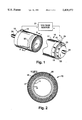
- FIG. 1 is a perspective view of a roller of the present invention with parts broken away;
- FIG. 2 is a cross sectional view of a portion of the roller of FIG. 1;
- FIG. 3 is a left end fragment of a longitudinal section of the roller of FIG. 1;
- FIG. 4 is a right end fragment of a longitudinal section of the roller of FIG. 1;
- FIG. 5 is a left end fragment of a longitudinal section of a second embodiment of the roller of the invention.
- FIG. 6 is a graph of two plots of log 10 ohms vs. temperature in selected directions through the roller of FIG. 1.
- FIG. 1 shows a preferred embodiment of a heater roller 10 of a type for use in copying machines, or in other industrial applications, such as steam-heated or induction-heated rollers for the paper making, printing, paper, film, and foil converting industries.
- a preferred embodiment of the heater roller 10 of the present invention has a core 11.
- the core material in the preferred embodiment is steel, but stainless steel, brass, aluminum, glass, or an FRP composite type material can also be used.
- the finished roller 10 includes suitable journal shafts 25 for disposition in suitable machine bearing structures of a type known in the art.
- This metal layer can be formed by plasma spraying a bond coating over the full outer surface of the core.
- a heat regulating layer 12 of 5 to 100 mils thickness is formed over the full outer surface of the bonding layer.
- This layer 12 is formed of a ceramic having a resistance that is considerably higher than the resistance of layer 13 at lower temperatures.
- Layer 12 in effect has a resistance of an insulating material at low temperature. As temperature increases, the resistance of layer 12 decreases and enters the range of a semiconductive material which will provide a path for current between layer 13 and core 11.
- Layer 12 functions like a variable resistor with specific resistance values corresponding to various temperatures.
- a heater layer 13 of 1 to 100 mils thickness is formed over the full outer surface of the temperature regulating layer 12.
- This layer 13 is semiconductive and is intended to be heated by resistive power dissipation to a specified and controlled temperature, so as to control the temperature of an outer functional layer 17.
- Two electrodes are formed by thin bands 18, 19 encircling the respective ends of the outer surface of the heater layer 13.
- a functional outer layer 17 is formed over the remaining outer surface of the heater layer 13.
- the outer functional layer 17 is made of ceramic or elastomeric/polymeric material.
- An electrical brush represented by element 15, contacts band 18 and is electrically connected to the positive (+) voltage terminal of voltage source 21.
- the core 11 also forms a ring-shaped band 22 extending from an opposite end of the roller 10 (FIG. 1).
- the voltage source 21 may supply either alternating current or direct current.
- a third brush 16 contacts band 19 and is also electrically connected to the grounded negative (-) terminal of the voltage source 21.
- electrical current which is represented by the arrows 26, 28, flows in a longitudinal direction relative to the roller 10 from positive electrode 18 to negative electrode 19.
- Current represented by arrow 27 flows in a radial direction between positive electrode 18 and the core 11.
- the resistance of the heat regulating layer 12 is electrically in parallel with the resistance of the heater layer 13.
- the heat regulating layer 12 is formed of semiconductive ceramic with a resistance characteristic such that it is more resistive when the heater layer 13 is operated at lower temperatures and decreases in resistance as the temperature increases. As temperature increases, the resistance of heat regulating layer 12 begins decreasing to divert current from layer 13 and thus lower the heat produced in layer 13 by resistive electrical power dissipation.
- the grounding of the core 11 is optional. In any event the core 11 will be much more conductive than the heat regulating layer 12, and thus current will be directed from electrode 18 radially from layer 13 through layer 12 to the core 11 and then to the negative electrodes 19 and 22, flowing back through layer 12 to reach electrode 19. If desired, a resistor 29 can be connected between the core 11 and ground to reduce current through the core 11 and reduce the voltage drop between the heating layer 13 and the core 11.
- the positioning of the brushes 15, 16 and 23 and the relative resistances of the layers 11, 12 and 13 may result in greater heating near brush 15 than in other portions of the roller. If desired, the positive and ground voltages on brushes 15, 16 and 23 can be switched in a sequence which provides for more uniform heating of the roller 10.
- the heater roller 10 is made as follows:
- Step 1 Grit blast surface of a steel core 11 to clean and roughen it to about a 200 to 300 micro inch R a surface.
- Step 2 Apply a bonding layer from 1 mil to 3 mils thickness of a nickel-aluminide material by plasma or thermal spraying with a 300 to 400 micro inch R a surface finish such as Metco 450 or 480. This step is optional but will improve the bond strength of the ceramic 12 to the core 11.
- Step 3 Apply the first ceramic layer 12 of 5 to 100 mils thickness using a blend of alumina and titania and by using plasma spraying techniques and equipment.
- the material is Norton 106 ceramic, which is an 87/13 blend of alumina and titania.
- the layer 12 is applied to a thickness of 20 mils.
- Other materials such as Metco 130, available from Metco Corp., Westbury, NY, can also be used for this layer.
- the preferred material is a blend of Metco 130 and Metco 131.
- This step is further carried out by spraying thin uniform sublayers to arrive at a desired thickness of the ceramic layer 12.
- the thinnest practical layer of plasma sprayed ceramic for an electrical grade coating having high integrity and uniformity is about 5 mils. In thinner layers, the peaks of the bond coat layer may protrude through the ceramic layer 12. Plasma sprayed ceramic can also be applied in much thicker layers, as great as 100 mils or more.
- the resistance of the ceramic layer 12 can be controlled by controlling the materials used in the plasma spraying process and by controlling the thickness of the layer 12.
- Resistance in the longitudinal direction along the roller increases in direct proportion to the length. In the radial direction, the resistance decreases as the area of the layer increases. If the length and circumference of the layer remain nearly constant, resistance will increase somewhat in the radial direction as the thickness of the ceramic layer 12 increases, while at same time the resistance in the longitudinal direction will decrease due to a larger cross sectional area produced by radial thickening of the layer.
- the resistance characteristic of the ceramic layer can be adjusted.
- the ceramic mixture consists of one conductive or semiconductive ceramic and another ceramic which is close to being an insulating material. Blends of more than two materials are possible.
- the term "conductive” material shall mean a material with a volume resistivity of 10 3 ohm-centimeters or less.
- the term “insulating” material shall mean a material with a volume resistivity of 10 10 ohm-centimeters or greater.
- the term “semiconductive” material shall mean a material with a volume resistivity between 10 3 ohm-centimeters and 10 10 ohm-centimeters.
- Chromium oxide (CrO 2 or CrO) is an example of a semiconductive or lower resistance ceramic material. The unsprayed powder is Cr 2 O 3 ; after spraying the material may be CrO or CrO 2 .
- Titanium dioxide also referred to as titania (TiO 2 )
- TiO 2 Titanium dioxide
- TiO 2 is an example of a conductive material when plasma sprayed. It can be used as the only component of the heater layer.
- the heat regulating layer it is blended with other insulating ceramics to provide a material with the variable resistance characteristic described herein.
- insulating ceramics such as zirconia or alumina can be blended with titania.
- the ceramic powders described herein are typically less than pure materials. Even the purest alumina commercially available is only 99.0% to 99.5% pure. Many grades of alumina contain several percent by weight of other metal oxides. For example, white or gray alumina may contain titania (titanium dioxide) (TiO 2 )in amounts from less than 5% up to at least 40%. An increase in the percentage of titania in the blend lowers the resistance of the material. Even though these materials are available as single powders, they are still blends of various ceramics. The electrical properties of the final ceramic layer are the sum of the individual contributions to resistance, capacitance, dielectric strength, etc. A single powder may be available that would exactly meet the electrical requirements.
- the preferred material for the heat regulating layer 12 is a blend of Metco 130 and Metco 131.
- Metco 130 is a mixture of 87% alumina and 13% titania
- Metco 131 is a mixture of 60% alumina and 40% titania.
- the electrical properties are determined in large part by the ratio of alumina to titania in the finished coating.
- the desired proportion of titania in the finished layer 12 is from 10% to 50%.
- Metco 130 and 131 can be blended since they can be purchased in the same particle size range and they have nearly the same density.
- Titania can be partially reduced to a suboxide by the presence of hydrogen or other reducing agents in the plasma flame. It is the suboxide (probably TiO rather than TiO 2 ) that is the semiconductor in the ceramic layer 16.
- Titanium dioxide is normally a dielectric material.
- the typical average chemical composition of titanium dioxide is 1.8 oxygen per molecule rather than 2.0 in a plasma sprayed coating. This level (and thus the coating properties) can be adjusted to some extent by raising or lowering the percent of hydrogen in the plasma flame.
- the normal primary gas is nitrogen or argon while the secondary gas is hydrogen or helium. The secondary gas raises the ionization potential of the mixture, thus increasing the power level at a given electrode current.
- the hydrogen level is adjusted to maintain the electrode voltage in the gun between 74 and 80 volts.
- the plasma spray parameters should be suitably adjusted to insure that the blend of materials in the finished ceramic layer 12 is the same as intended. All of the powders mentioned do not require the same power levels, spray distance, and other parameters. Thus, adjustment of spray distance, for example, may increase the deposit efficiency of one powder over the other and change the material blend in the finished coating.
- Plasma sprayed ceramic coatings can be applied in one pass (layer) of the plasma gun or in multiple passes.
- the normal method for most types of coating applications is to apply multiple thin coatings of ceramic and build up to the required thickness.
- the ceramic layer described above has a uniform ceramic composition, the sublayers of ceramic in the resulting layer 12 do not have to have the same composition.
- the coating can be designed to have a different resistance at the surface than the average bulk of the material.
- Step 4 Apply the second ceramic layer 13 over the first ceramic layer 12.
- the upper ceramic heating layer 13 is Miller 1097, a 100 percent titania material, which is applied in a layer 2 to 3 mils thick.
- Other materials such as Metco 102 ceramic powder, available from Metco Corp., Westbury, New York, USA, can also be used.
- Titanium dioxide (TiO 2 ) is normally an electrical insulating material. However, when the material is plasma-sprayed, some of the dioxide form is chemically reduced to a conductive sub-oxide (mono-oxide) form, rendering the deposited coating electrically conductive.
- the ceramic heating layer 13 is then finished to the proper dimensions and surface finish (diamond, silicon carbide abrasives, etc.). After finishing, the ceramic heating layer 13 is typically 1 to 100 mils thick with a surface finish 20 to 70 micro inches R a . In other embodiments, it may be thicker than 10 mils and vary in surface roughness from 10 to 250 micro inches R a .
- Step 5 The outer functional layer 17 is then applied.
- This may be any material that can be applied by thermal spraying, any elastomer, thermoplastic or thermoset resin, suitable for the roller application.
- the outer functional layer 17 can be an insulator, or if it is a conductor, it is insulated from heater layer 13.
- Ceramic surfaces can perform at temperatures as high as 500 degrees F.-600 degrees F. in rollers with metal cores, and potentially up to 2000 degrees F. for rollers with ceramic cores.
- the outer electrodes 18, 19 are formed by 1/2-inch wide bands of an alloy, Metco 450, available from Metco Corp. of Westbury, NY.
- a roller 10 having a steel core 11 was provided with a temperature regulating layer 12 of Norton 106 ceramic, an 87/13 alumina/titania blend ceramic, 20 mils thick.
- a ceramic heating layer 13, 2 to 3 mils thick was then formed over the regulating layer 12.
- the outer electrodes were formed by 1/2-inch wide bands of the alloy, Metco 450, available from Metco Corp. of Westbury, NY.
- a roller according to the first example was constructed and tested with results as shown in FIG. 6.
- the curves are mean straight-line plots through a series of points which fall on either side of the resulting plots.
- the resistance of the roller 10 from electrode 15 to electrode 16 is shown in the first plot 30 to be about 15 ohms at 200 degrees F. and about 6 ohms at 600 degree F. (log 1.3 rs. log 0.8). This means that the resistance of the heater layer 13, through which current travels when resistance in the regulating layer is high, does not change greatly in the longitudinal direction. As shown by the second plot 31, the resistance changes in the radial direction, as measured between the positive electrode 15 and the core electrode 23, from about 6000 ohms at 200 degrees F. to about 25 ohms at 600 degree F. This is a drop of greater than two orders of magnitude (factor of 10) over a range of 400 degrees F. to approximately the same order of magnitude as resistance in the longitudinal direction. At elevated temperatures, the lower resistance of the regulating layer 12 diverts current from the heater layer 13. The regulating layer 12 may also begins to act as a second heater layer 13.
- the change in resistance of the regulating layer 12 is directional, that it changes more in the radial direction, than in the longitudinal direction. Electrical current in the roller is therefore diverted radially to the core 11 and then through the conductive core 11 to the negative electrodes 16 and 23.
- the heating in layer 13 may also be controlled, as seen in FIG. 1, by providing conductive bands 32 which encircle the mid-section of the roller 10 between layer 13 and outer functional layer 17. These provide alternative paths for current to bypass portions of layer 13, as current travels in the longitudinal direction, so as reduce heating in the midsection of the roller 10.
- roller 50 includes steel core 33, a ceramic heating layer 35 and a ceramic heat-regulating layer 34, the ceramic layers being of the ceramic compositions discussed above.
- Positive electrode band 36 runs around the inner circumference of the roller 50, and is electrically connected to positive voltage source 40 (+V). This band 36 may be formed on layer 35, and when layer 35 rotates, the band would move with it but remain in contact with a stationary contact (not shown). Wires extend through an opening in a journal shaft 39, which is mounted in end cap 38 enclosing one end of the hollow roller core 33.
- a second conductive electrode band 37 is connected to a ground terminal 41 on an external power source. Terminals 40 and 41 are connected to a slip ring assembly, such that the wires electrically connecting terminals 40, 41 and bands 36, 37 remain stationary as the roller 50 rotates.
- Heat-regulating bands 42 may be provided around the inside mid-section of the roller 50, similar to the roller 10 shown in FIG. 1, to help relieve heating in layer 35 by providing current bypass portions that do not heat as much as layer 35.
Abstract
Description
Claims (10)
Priority Applications (8)
| Application Number | Priority Date | Filing Date | Title |
|---|---|---|---|
| US08/071,135 US5408070A (en) | 1992-11-09 | 1993-06-02 | Ceramic heater roller with thermal regulating layer |
| US08/084,650 US5420395A (en) | 1992-11-09 | 1993-06-28 | Ceramic heater roller with zone heating |
| PCT/US1994/001173 WO1994028691A1 (en) | 1993-06-02 | 1994-01-31 | Ceramic heater roller with thermal regulating layer |
| EP94908688A EP0701766A1 (en) | 1993-06-02 | 1994-01-31 | Ceramic heater roller with thermal regulating layer |
| JP7500592A JPH08510859A (en) | 1993-06-02 | 1994-01-31 | Ceramic heater roller with heat regulation layer |
| CA002163877A CA2163877A1 (en) | 1993-06-02 | 1994-01-31 | Ceramic heater roller with thermal regulating layer |
| MX9404006A MX9404006A (en) | 1993-06-02 | 1994-05-27 | CERAMIC HEATING ROLLER WITH THERMAL REGULATING LAYER. |
| KR1019950705435A KR960702980A (en) | 1993-06-02 | 1995-12-02 | CERAMIC HEATER ROLLER WITH THERMAL REGULATING LAYER |
Applications Claiming Priority (3)
| Application Number | Priority Date | Filing Date | Title |
|---|---|---|---|
| US97344792A | 1992-11-09 | 1992-11-09 | |
| US315693A | 1993-01-12 | 1993-01-12 | |
| US08/071,135 US5408070A (en) | 1992-11-09 | 1993-06-02 | Ceramic heater roller with thermal regulating layer |
Related Parent Applications (2)
| Application Number | Title | Priority Date | Filing Date |
|---|---|---|---|
| US97344792A Continuation-In-Part | 1992-11-09 | 1992-11-09 | |
| US315693A Continuation-In-Part | 1992-11-09 | 1993-01-12 |
Related Child Applications (1)
| Application Number | Title | Priority Date | Filing Date |
|---|---|---|---|
| US08/084,650 Continuation-In-Part US5420395A (en) | 1992-11-09 | 1993-06-28 | Ceramic heater roller with zone heating |
Publications (1)
| Publication Number | Publication Date |
|---|---|
| US5408070A true US5408070A (en) | 1995-04-18 |
Family
ID=22099462
Family Applications (1)
| Application Number | Title | Priority Date | Filing Date |
|---|---|---|---|
| US08/071,135 Expired - Fee Related US5408070A (en) | 1992-11-09 | 1993-06-02 | Ceramic heater roller with thermal regulating layer |
Country Status (7)
| Country | Link |
|---|---|
| US (1) | US5408070A (en) |
| EP (1) | EP0701766A1 (en) |
| JP (1) | JPH08510859A (en) |
| KR (1) | KR960702980A (en) |
| CA (1) | CA2163877A1 (en) |
| MX (1) | MX9404006A (en) |
| WO (1) | WO1994028691A1 (en) |
Cited By (35)
| Publication number | Priority date | Publication date | Assignee | Title |
|---|---|---|---|---|
| US5616263A (en) * | 1992-11-09 | 1997-04-01 | American Roller Company | Ceramic heater roller |
| USRE35698E (en) * | 1992-10-02 | 1997-12-23 | Xerox Corporation | Donor roll for scavengeless development in a xerographic apparatus |
| US5722025A (en) * | 1995-10-24 | 1998-02-24 | Minolta Co., Ltd. | Fixing device |
| US5760375A (en) * | 1996-10-08 | 1998-06-02 | Hall; Timothy G. | Heated rollers |
| US6069346A (en) * | 1993-01-12 | 2000-05-30 | American Roller Company | Ceramic heater roller with ground shield and fault detection |
| WO2000057674A1 (en) * | 1999-03-24 | 2000-09-28 | Watlow Polymer Technologies | Heating element suitable for preconditioning print media |
| US6148169A (en) * | 1998-10-06 | 2000-11-14 | Ricoh Company, Ltd. | Device for fixing an image on a recording medium |
| US6222166B1 (en) * | 1999-08-09 | 2001-04-24 | Watlow Electric Manufacturing Co. | Aluminum substrate thick film heater |
| US6263158B1 (en) | 1999-05-11 | 2001-07-17 | Watlow Polymer Technologies | Fibrous supported polymer encapsulated electrical component |
| US6285006B1 (en) | 2000-07-12 | 2001-09-04 | American Roller Company | Ceramic heater/fuser roller with internal heater |
| US6304740B1 (en) | 2000-02-10 | 2001-10-16 | Nexpress Solutions Llc | Externally heated external hearted rollers |
| US6392206B1 (en) | 2000-04-07 | 2002-05-21 | Waltow Polymer Technologies | Modular heat exchanger |
| US6392208B1 (en) | 1999-08-06 | 2002-05-21 | Watlow Polymer Technologies | Electrofusing of thermoplastic heating elements and elements made thereby |
| US6432344B1 (en) | 1994-12-29 | 2002-08-13 | Watlow Polymer Technology | Method of making an improved polymeric immersion heating element with skeletal support and optional heat transfer fins |
| US6433317B1 (en) | 2000-04-07 | 2002-08-13 | Watlow Polymer Technologies | Molded assembly with heating element captured therein |
| US6516142B2 (en) | 2001-01-08 | 2003-02-04 | Watlow Polymer Technologies | Internal heating element for pipes and tubes |
| US6519835B1 (en) | 2000-08-18 | 2003-02-18 | Watlow Polymer Technologies | Method of formable thermoplastic laminate heated element assembly |
| US6523262B1 (en) * | 2000-05-12 | 2003-02-25 | American Roller Company, Llc | Elastomer-covered roller having a thermally sprayed permeable bonding material |
| US20030185595A1 (en) * | 2002-03-28 | 2003-10-02 | Samsung Electronics Co. | Developing unit and density control method in electrophotography |
| US20030218006A1 (en) * | 2002-03-13 | 2003-11-27 | Richard Sutorius | Hot runner heater device and method of manufacture thereof |
| US6762396B2 (en) | 1997-05-06 | 2004-07-13 | Thermoceramix, Llc | Deposited resistive coatings |
| US20050008382A1 (en) * | 2002-02-28 | 2005-01-13 | Seiko Epson Corporation | Image forming apparatus and image forming method |
| US20050023218A1 (en) * | 2003-07-28 | 2005-02-03 | Peter Calandra | System and method for automatically purifying solvents |
| US6919543B2 (en) | 2000-11-29 | 2005-07-19 | Thermoceramix, Llc | Resistive heaters and uses thereof |
| US20050169671A1 (en) * | 2002-03-28 | 2005-08-04 | Samsung Electronics Co. | Developing unit and density control method in electrophotography |
| US7241131B1 (en) * | 2000-06-19 | 2007-07-10 | Husky Injection Molding Systems Ltd. | Thick film heater apparatus |
| US20090016755A1 (en) * | 2002-03-28 | 2009-01-15 | Samsung Electronics Co., Ltd. | Developing unit and density control method in electrophotography |
| US20090272728A1 (en) * | 2008-05-01 | 2009-11-05 | Thermoceramix Inc. | Cooking appliances using heater coatings |
| US20100108662A1 (en) * | 2008-10-30 | 2010-05-06 | Taylor Bruce F | Plasticating Barrel With Integrated Exterior Heater Layer |
| US20100124448A1 (en) * | 2008-11-14 | 2010-05-20 | Bradley Leonard Beach | Resistive Heating Hot Roll Fuser |
| TWI409176B (en) * | 2010-12-31 | 2013-09-21 | E Ink Holdings Inc | Electrothermal transfer device and electrothermal transfer method |
| US20130341823A1 (en) * | 2011-03-11 | 2013-12-26 | Sharp Kabushiki Kaisha | Mold, method for producing mold, and method for producing nanoimprint film |
| US9420638B2 (en) | 2011-08-05 | 2016-08-16 | Nordson Corporation | Multi-part electrodes for a heater layer |
| US20170303340A1 (en) * | 2016-04-15 | 2017-10-19 | Borgwarner Ludwigsburg Gmbh | Heating rod comprising a housing with dielectric coating |
| TWI648753B (en) * | 2017-08-09 | 2019-01-21 | 曾吉旺 | Mechanical control module and variable resistor assembly thereof |
Families Citing this family (1)
| Publication number | Priority date | Publication date | Assignee | Title |
|---|---|---|---|---|
| GB2359234A (en) * | 1999-12-10 | 2001-08-15 | Jeffery Boardman | Resistive heating elements composed of binary metal oxides, the metals having different valencies |
Citations (22)
| Publication number | Priority date | Publication date | Assignee | Title |
|---|---|---|---|---|
| US3521126A (en) * | 1967-07-28 | 1970-07-21 | Addressograph Multigraph | Roller charging apparatus |
| US3607343A (en) * | 1965-10-04 | 1971-09-21 | Metco Inc | Flame spray powders and process with alumina having titanium dioxide bonded to the surface thereof |
| US4290555A (en) * | 1979-02-21 | 1981-09-22 | Nippon Sanso K. K. | Method for supplying powder to be used in home spray coating operation |
| US4413170A (en) * | 1980-06-24 | 1983-11-01 | Thomson-Csf | Thermal printing head |
| JPS59102267A (en) * | 1982-12-03 | 1984-06-13 | Hitachi Metals Ltd | Equalizing heat roll |
| US4628183A (en) * | 1983-12-19 | 1986-12-09 | Canon Kabushiki Kaisha | Heating-fixing roller and fixing device having the same |
| US4724305A (en) * | 1986-03-07 | 1988-02-09 | Hitachi Metals, Ltd. | Directly-heating roller for fuse-fixing toner images |
| US4743940A (en) * | 1986-09-22 | 1988-05-10 | Onoda Cement Company, Ltd. | Thermal fixing roller for use in a copying machine and method for manufacturing the same |
| US4791275A (en) * | 1986-04-07 | 1988-12-13 | Imi-Tech Corporation | High temperature compliant roll particularly adapted for xerography |
| JPS6421887A (en) * | 1987-07-16 | 1989-01-25 | Hitachi Cable | Sheet heater |
| US4810858A (en) * | 1987-11-02 | 1989-03-07 | Eastman Kodak Company | Fusing roller |
| US4813372A (en) * | 1986-05-08 | 1989-03-21 | Kabushiki Kaisha Toshiba | Toner image fixing apparatus |
| US4820904A (en) * | 1987-11-02 | 1989-04-11 | Eastman Kodak Company | Electrical contacting device for fusing roller |
| DE3836857A1 (en) * | 1987-10-30 | 1989-05-11 | Sharp Kk | Fusion device for an electrophotographic copier and method for producing a heating roller intended therefor |
| US4841154A (en) * | 1986-07-18 | 1989-06-20 | Matsushita Electric Industrial Co., Ltd. | Thermal copying apparatus |
| US4874927A (en) * | 1987-06-09 | 1989-10-17 | Hitachi Metals, Ltd. | Heating roll for fixing toner |
| US5047612A (en) * | 1990-02-05 | 1991-09-10 | General Electric Company | Apparatus and method for controlling powder deposition in a plasma spray process |
| US5065193A (en) * | 1989-05-24 | 1991-11-12 | Onoda Cement Co., Ltd. | Heat fixing roll for copying machine, method of producing the same and electronic copying machine provided with the same |
| US5089856A (en) * | 1989-02-06 | 1992-02-18 | Spectrum Sciences B.V. | Image transfer apparatus incorporating an internal heater |
| US5159173A (en) * | 1990-09-26 | 1992-10-27 | General Electric Company | Apparatus for reducing plasma constriction by intermediate injection of hydrogen in RF plasma gun |
| US5191381A (en) * | 1991-08-12 | 1993-03-02 | Jie Yuan | PTC ceramic heat roller for fixing toner image |
| US5280329A (en) * | 1991-08-08 | 1994-01-18 | Tokyo Electric Co., Ltd. | Fixing device |
Family Cites Families (1)
| Publication number | Priority date | Publication date | Assignee | Title |
|---|---|---|---|---|
| JPS55164859A (en) * | 1979-06-11 | 1980-12-22 | Toshiba Corp | Fixing device of electrophotographic copier |
-
1993
- 1993-06-02 US US08/071,135 patent/US5408070A/en not_active Expired - Fee Related
-
1994
- 1994-01-31 JP JP7500592A patent/JPH08510859A/en active Pending
- 1994-01-31 WO PCT/US1994/001173 patent/WO1994028691A1/en not_active Application Discontinuation
- 1994-01-31 CA CA002163877A patent/CA2163877A1/en not_active Abandoned
- 1994-01-31 EP EP94908688A patent/EP0701766A1/en not_active Withdrawn
- 1994-05-27 MX MX9404006A patent/MX9404006A/en not_active IP Right Cessation
-
1995
- 1995-12-02 KR KR1019950705435A patent/KR960702980A/en not_active Application Discontinuation
Patent Citations (22)
| Publication number | Priority date | Publication date | Assignee | Title |
|---|---|---|---|---|
| US3607343A (en) * | 1965-10-04 | 1971-09-21 | Metco Inc | Flame spray powders and process with alumina having titanium dioxide bonded to the surface thereof |
| US3521126A (en) * | 1967-07-28 | 1970-07-21 | Addressograph Multigraph | Roller charging apparatus |
| US4290555A (en) * | 1979-02-21 | 1981-09-22 | Nippon Sanso K. K. | Method for supplying powder to be used in home spray coating operation |
| US4413170A (en) * | 1980-06-24 | 1983-11-01 | Thomson-Csf | Thermal printing head |
| JPS59102267A (en) * | 1982-12-03 | 1984-06-13 | Hitachi Metals Ltd | Equalizing heat roll |
| US4628183A (en) * | 1983-12-19 | 1986-12-09 | Canon Kabushiki Kaisha | Heating-fixing roller and fixing device having the same |
| US4724305A (en) * | 1986-03-07 | 1988-02-09 | Hitachi Metals, Ltd. | Directly-heating roller for fuse-fixing toner images |
| US4791275A (en) * | 1986-04-07 | 1988-12-13 | Imi-Tech Corporation | High temperature compliant roll particularly adapted for xerography |
| US4813372A (en) * | 1986-05-08 | 1989-03-21 | Kabushiki Kaisha Toshiba | Toner image fixing apparatus |
| US4841154A (en) * | 1986-07-18 | 1989-06-20 | Matsushita Electric Industrial Co., Ltd. | Thermal copying apparatus |
| US4743940A (en) * | 1986-09-22 | 1988-05-10 | Onoda Cement Company, Ltd. | Thermal fixing roller for use in a copying machine and method for manufacturing the same |
| US4874927A (en) * | 1987-06-09 | 1989-10-17 | Hitachi Metals, Ltd. | Heating roll for fixing toner |
| JPS6421887A (en) * | 1987-07-16 | 1989-01-25 | Hitachi Cable | Sheet heater |
| DE3836857A1 (en) * | 1987-10-30 | 1989-05-11 | Sharp Kk | Fusion device for an electrophotographic copier and method for producing a heating roller intended therefor |
| US4820904A (en) * | 1987-11-02 | 1989-04-11 | Eastman Kodak Company | Electrical contacting device for fusing roller |
| US4810858A (en) * | 1987-11-02 | 1989-03-07 | Eastman Kodak Company | Fusing roller |
| US5089856A (en) * | 1989-02-06 | 1992-02-18 | Spectrum Sciences B.V. | Image transfer apparatus incorporating an internal heater |
| US5065193A (en) * | 1989-05-24 | 1991-11-12 | Onoda Cement Co., Ltd. | Heat fixing roll for copying machine, method of producing the same and electronic copying machine provided with the same |
| US5047612A (en) * | 1990-02-05 | 1991-09-10 | General Electric Company | Apparatus and method for controlling powder deposition in a plasma spray process |
| US5159173A (en) * | 1990-09-26 | 1992-10-27 | General Electric Company | Apparatus for reducing plasma constriction by intermediate injection of hydrogen in RF plasma gun |
| US5280329A (en) * | 1991-08-08 | 1994-01-18 | Tokyo Electric Co., Ltd. | Fixing device |
| US5191381A (en) * | 1991-08-12 | 1993-03-02 | Jie Yuan | PTC ceramic heat roller for fixing toner image |
Non-Patent Citations (3)
| Title |
|---|
| Patent Abstract of Japan JP55164859, Dec. 22, 1980, Toshiba Corp, Inventor Nakajima Schunichi. * |
| Patent Abstract of Japan JP55164859, Dec. 22, 1980, Toshiba Corp, Inventor-Nakajima Schunichi. |
| PCT International Search Report for PCT/US94/01173 dated Jun. 3, 1994. * |
Cited By (50)
| Publication number | Priority date | Publication date | Assignee | Title |
|---|---|---|---|---|
| USRE35698E (en) * | 1992-10-02 | 1997-12-23 | Xerox Corporation | Donor roll for scavengeless development in a xerographic apparatus |
| US5616263A (en) * | 1992-11-09 | 1997-04-01 | American Roller Company | Ceramic heater roller |
| US6069346A (en) * | 1993-01-12 | 2000-05-30 | American Roller Company | Ceramic heater roller with ground shield and fault detection |
| US6432344B1 (en) | 1994-12-29 | 2002-08-13 | Watlow Polymer Technology | Method of making an improved polymeric immersion heating element with skeletal support and optional heat transfer fins |
| US5722025A (en) * | 1995-10-24 | 1998-02-24 | Minolta Co., Ltd. | Fixing device |
| US5760375A (en) * | 1996-10-08 | 1998-06-02 | Hall; Timothy G. | Heated rollers |
| US6762396B2 (en) | 1997-05-06 | 2004-07-13 | Thermoceramix, Llc | Deposited resistive coatings |
| US6148169A (en) * | 1998-10-06 | 2000-11-14 | Ricoh Company, Ltd. | Device for fixing an image on a recording medium |
| WO2000057674A1 (en) * | 1999-03-24 | 2000-09-28 | Watlow Polymer Technologies | Heating element suitable for preconditioning print media |
| US6263158B1 (en) | 1999-05-11 | 2001-07-17 | Watlow Polymer Technologies | Fibrous supported polymer encapsulated electrical component |
| US6434328B2 (en) | 1999-05-11 | 2002-08-13 | Watlow Polymer Technology | Fibrous supported polymer encapsulated electrical component |
| US6392208B1 (en) | 1999-08-06 | 2002-05-21 | Watlow Polymer Technologies | Electrofusing of thermoplastic heating elements and elements made thereby |
| US6222166B1 (en) * | 1999-08-09 | 2001-04-24 | Watlow Electric Manufacturing Co. | Aluminum substrate thick film heater |
| US6304740B1 (en) | 2000-02-10 | 2001-10-16 | Nexpress Solutions Llc | Externally heated external hearted rollers |
| US6748646B2 (en) | 2000-04-07 | 2004-06-15 | Watlow Polymer Technologies | Method of manufacturing a molded heating element assembly |
| US6392206B1 (en) | 2000-04-07 | 2002-05-21 | Waltow Polymer Technologies | Modular heat exchanger |
| US6433317B1 (en) | 2000-04-07 | 2002-08-13 | Watlow Polymer Technologies | Molded assembly with heating element captured therein |
| US6666806B2 (en) * | 2000-05-12 | 2003-12-23 | American Roller Company, Llc | Elastomer-covered roller having a thermally sprayed permeable bonding material |
| US6523262B1 (en) * | 2000-05-12 | 2003-02-25 | American Roller Company, Llc | Elastomer-covered roller having a thermally sprayed permeable bonding material |
| US7241131B1 (en) * | 2000-06-19 | 2007-07-10 | Husky Injection Molding Systems Ltd. | Thick film heater apparatus |
| WO2002005594A3 (en) * | 2000-07-12 | 2002-07-04 | American Roller Co | Ceramic heater/fuser roller with internal heater |
| WO2002005594A2 (en) * | 2000-07-12 | 2002-01-17 | American Roller Company, Llc | Ceramic heater/fuser roller with internal heater |
| US6285006B1 (en) | 2000-07-12 | 2001-09-04 | American Roller Company | Ceramic heater/fuser roller with internal heater |
| US6541744B2 (en) | 2000-08-18 | 2003-04-01 | Watlow Polymer Technologies | Packaging having self-contained heater |
| US6519835B1 (en) | 2000-08-18 | 2003-02-18 | Watlow Polymer Technologies | Method of formable thermoplastic laminate heated element assembly |
| US6919543B2 (en) | 2000-11-29 | 2005-07-19 | Thermoceramix, Llc | Resistive heaters and uses thereof |
| US6539171B2 (en) | 2001-01-08 | 2003-03-25 | Watlow Polymer Technologies | Flexible spirally shaped heating element |
| US6516142B2 (en) | 2001-01-08 | 2003-02-04 | Watlow Polymer Technologies | Internal heating element for pipes and tubes |
| US6744978B2 (en) | 2001-01-08 | 2004-06-01 | Watlow Polymer Technologies | Small diameter low watt density immersion heating element |
| US20050008382A1 (en) * | 2002-02-28 | 2005-01-13 | Seiko Epson Corporation | Image forming apparatus and image forming method |
| US6985681B2 (en) * | 2002-02-28 | 2006-01-10 | Seiko Epson Corporation | Image forming apparatus and image forming method |
| US20030218006A1 (en) * | 2002-03-13 | 2003-11-27 | Richard Sutorius | Hot runner heater device and method of manufacture thereof |
| US7034258B2 (en) | 2002-03-13 | 2006-04-25 | Watlow Electric Manufacturing Company | Hot runner heater device and method of manufacture thereof |
| US20050169671A1 (en) * | 2002-03-28 | 2005-08-04 | Samsung Electronics Co. | Developing unit and density control method in electrophotography |
| US7024126B2 (en) * | 2002-03-28 | 2006-04-04 | Samsung Electronics Co., Ltd. | Developing unit and density control method in electrophotography |
| US20030185595A1 (en) * | 2002-03-28 | 2003-10-02 | Samsung Electronics Co. | Developing unit and density control method in electrophotography |
| US20090016755A1 (en) * | 2002-03-28 | 2009-01-15 | Samsung Electronics Co., Ltd. | Developing unit and density control method in electrophotography |
| US7664437B2 (en) | 2002-03-28 | 2010-02-16 | Samsung Electronics Co., Ltd. | Developing unit and density control method in electrophotography |
| US20050023218A1 (en) * | 2003-07-28 | 2005-02-03 | Peter Calandra | System and method for automatically purifying solvents |
| US20090272728A1 (en) * | 2008-05-01 | 2009-11-05 | Thermoceramix Inc. | Cooking appliances using heater coatings |
| US20100108662A1 (en) * | 2008-10-30 | 2010-05-06 | Taylor Bruce F | Plasticating Barrel With Integrated Exterior Heater Layer |
| US8247747B2 (en) | 2008-10-30 | 2012-08-21 | Xaloy, Inc. | Plasticating barrel with integrated exterior heater layer |
| US20100124448A1 (en) * | 2008-11-14 | 2010-05-20 | Bradley Leonard Beach | Resistive Heating Hot Roll Fuser |
| US8180269B2 (en) * | 2008-11-14 | 2012-05-15 | Lexmark International, Inc. | Resistive heating hot roll fuser |
| TWI409176B (en) * | 2010-12-31 | 2013-09-21 | E Ink Holdings Inc | Electrothermal transfer device and electrothermal transfer method |
| US20130341823A1 (en) * | 2011-03-11 | 2013-12-26 | Sharp Kabushiki Kaisha | Mold, method for producing mold, and method for producing nanoimprint film |
| US10155340B2 (en) * | 2011-03-11 | 2018-12-18 | Sharp Kabushiki Kaisha | Mold, method for producing mold, and method for producing nanoimprint film |
| US9420638B2 (en) | 2011-08-05 | 2016-08-16 | Nordson Corporation | Multi-part electrodes for a heater layer |
| US20170303340A1 (en) * | 2016-04-15 | 2017-10-19 | Borgwarner Ludwigsburg Gmbh | Heating rod comprising a housing with dielectric coating |
| TWI648753B (en) * | 2017-08-09 | 2019-01-21 | 曾吉旺 | Mechanical control module and variable resistor assembly thereof |
Also Published As
| Publication number | Publication date |
|---|---|
| KR960702980A (en) | 1996-05-23 |
| MX9404006A (en) | 1995-01-31 |
| CA2163877A1 (en) | 1994-12-08 |
| WO1994028691A1 (en) | 1994-12-08 |
| EP0701766A1 (en) | 1996-03-20 |
| JPH08510859A (en) | 1996-11-12 |
Similar Documents
| Publication | Publication Date | Title |
|---|---|---|
| US5408070A (en) | Ceramic heater roller with thermal regulating layer | |
| US5616263A (en) | Ceramic heater roller | |
| US5420395A (en) | Ceramic heater roller with zone heating | |
| CA2146339C (en) | Charging roller with blended ceramic layer | |
| EP0241714B1 (en) | Directly-heated roller for fixing toner images | |
| US6376816B2 (en) | Thin film tubular heater | |
| US6285006B1 (en) | Ceramic heater/fuser roller with internal heater | |
| US6069346A (en) | Ceramic heater roller with ground shield and fault detection | |
| US5609553A (en) | Ceramic roller for ESA printing and coating | |
| CA2153598C (en) | Ceramic heater roller and methods of making same | |
| US6290823B1 (en) | Convertible electrode roller for corona treating systems | |
| US6127654A (en) | Method for manufacturing heating element | |
| JP3109328B2 (en) | Heat fixing device | |
| MXPA96005328A (en) | Ceramic roller for printing and coating machines with electrostat help | |
| JPH07296945A (en) | Heating roller for fixing |
Legal Events
| Date | Code | Title | Description |
|---|---|---|---|
| AS | Assignment |
Owner name: AMERICAN ROLLER COMPANY, WISCONSIN Free format text: ASSIGNMENT OF ASSIGNORS INTEREST;ASSIGNOR:HYLLBERG, BRUCE E.;REEL/FRAME:006592/0798 Effective date: 19930526 |
|
| CC | Certificate of correction | ||
| FPAY | Fee payment |
Year of fee payment: 4 |
|
| AS | Assignment |
Owner name: BANK NATIONAL ASSOCIATION, U.S., MINNESOTA Free format text: SECURITY INTEREST;ASSIGNOR:AMERICAN ROLLER COMPANY;REEL/FRAME:011934/0698 Effective date: 20010621 |
|
| AS | Assignment |
Owner name: CM AMERICAN ROLLER COMPANY, LLC, WISCONSIN Free format text: ASSIGNMENT OF ASSIGNORS INTEREST;ASSIGNOR:AMERICAN ROLLER COMPANY;REEL/FRAME:012447/0267 Effective date: 20011231 |
|
| AS | Assignment |
Owner name: LASALLE BUSINESS CREDIT, INC., ILLINOIS Free format text: SECURITY AGREEMENT;ASSIGNOR:CM AMERICAN ROLLER COMPANY, LLC;REEL/FRAME:012762/0111 Effective date: 20011231 |
|
| AS | Assignment |
Owner name: AMERICAN ROLLER COMPANY, ILLINOIS Free format text: RELEASE OF SECURITY AGREEMENT;ASSIGNOR:U.S. BANK NATIONAL ASSOCIATION;REEL/FRAME:012551/0927 Effective date: 20011228 |
|
| AS | Assignment |
Owner name: AMERICAN ROLLER COMPANY, LLC, WISCONSIN Free format text: CHANGE OF NAME;ASSIGNOR:CM AMERICAN ROLLER COMPANY, LLC;REEL/FRAME:012631/0654 Effective date: 20020110 |
|
| REMI | Maintenance fee reminder mailed | ||
| LAPS | Lapse for failure to pay maintenance fees | ||
| LAPS | Lapse for failure to pay maintenance fees |
Free format text: PATENT EXPIRED FOR FAILURE TO PAY MAINTENANCE FEES (ORIGINAL EVENT CODE: EXP.); ENTITY STATUS OF PATENT OWNER: LARGE ENTITY |
|
| STCH | Information on status: patent discontinuation |
Free format text: PATENT EXPIRED DUE TO NONPAYMENT OF MAINTENANCE FEES UNDER 37 CFR 1.362 |
|
| FP | Lapsed due to failure to pay maintenance fee |
Effective date: 20030418 |
|
| AS | Assignment |
Owner name: AMERICAN ROLLER HOLDING COMPANY, LLC, ILLINOIS Free format text: ASSIGNMENT OF ASSIGNORS INTEREST;ASSIGNOR:AMERICAN ROLLER COMPANY, LLC;REEL/FRAME:014718/0121 Effective date: 20031125 |
|
| AS | Assignment |
Owner name: AMERICAN ROLLER COMPANY, LLC, WISCONSIN Free format text: ASSIGNMENT OF ASSIGNORS INTEREST;ASSIGNOR:AMERICAN ROLLER HOLDING COMPANY, LLC;REEL/FRAME:014754/0324 Effective date: 20031201 |
|
| AS | Assignment |
Owner name: LASALLE BUSINESS CREDIT, LLC, ILLINOIS Free format text: SECURITY AGREEMENT;ASSIGNOR:AMERICAN ROLLER COMPANY, LLC;REEL/FRAME:014845/0300 Effective date: 20031201 |
|
| AS | Assignment |
Owner name: AMERICAN ROLLER COMPANY, LLC, WISCONSIN Free format text: RELEASE BY SECURED PARTY;ASSIGNOR:CIBC BANK USA (AS ASSIGNEE OF LASALLE BUSINESS CREDIT, LLC);REEL/FRAME:048506/0373 Effective date: 20190207 |
|
| AS | Assignment |
Owner name: CM AMERICAN ROLLER COMPANY, LLC, WISCONSIN Free format text: RELEASE BY SECURED PARTY;ASSIGNOR:CIBC BANK USA (AS ASSIGNEE OF LASALLE BUSINESS CREDIT, INC.);REEL/FRAME:048550/0611 Effective date: 20190305 |