US5416702A - Vehicle electrical-load limiting apparatus - Google Patents
Vehicle electrical-load limiting apparatus Download PDFInfo
- Publication number
- US5416702A US5416702A US07/884,525 US88452592A US5416702A US 5416702 A US5416702 A US 5416702A US 88452592 A US88452592 A US 88452592A US 5416702 A US5416702 A US 5416702A
- Authority
- US
- United States
- Prior art keywords
- electrical loads
- electrical
- vehicle
- restriction
- load
- Prior art date
- Legal status (The legal status is an assumption and is not a legal conclusion. Google has not performed a legal analysis and makes no representation as to the accuracy of the status listed.)
- Expired - Lifetime
Links
Images


Classifications
-
- B—PERFORMING OPERATIONS; TRANSPORTING
- B60—VEHICLES IN GENERAL
- B60L—PROPULSION OF ELECTRICALLY-PROPELLED VEHICLES; SUPPLYING ELECTRIC POWER FOR AUXILIARY EQUIPMENT OF ELECTRICALLY-PROPELLED VEHICLES; ELECTRODYNAMIC BRAKE SYSTEMS FOR VEHICLES IN GENERAL; MAGNETIC SUSPENSION OR LEVITATION FOR VEHICLES; MONITORING OPERATING VARIABLES OF ELECTRICALLY-PROPELLED VEHICLES; ELECTRIC SAFETY DEVICES FOR ELECTRICALLY-PROPELLED VEHICLES
- B60L1/00—Supplying electric power to auxiliary equipment of vehicles
- B60L1/003—Supplying electric power to auxiliary equipment of vehicles to auxiliary motors, e.g. for pumps, compressors
-
- B—PERFORMING OPERATIONS; TRANSPORTING
- B60—VEHICLES IN GENERAL
- B60L—PROPULSION OF ELECTRICALLY-PROPELLED VEHICLES; SUPPLYING ELECTRIC POWER FOR AUXILIARY EQUIPMENT OF ELECTRICALLY-PROPELLED VEHICLES; ELECTRODYNAMIC BRAKE SYSTEMS FOR VEHICLES IN GENERAL; MAGNETIC SUSPENSION OR LEVITATION FOR VEHICLES; MONITORING OPERATING VARIABLES OF ELECTRICALLY-PROPELLED VEHICLES; ELECTRIC SAFETY DEVICES FOR ELECTRICALLY-PROPELLED VEHICLES
- B60L15/00—Methods, circuits, or devices for controlling the traction-motor speed of electrically-propelled vehicles
- B60L15/20—Methods, circuits, or devices for controlling the traction-motor speed of electrically-propelled vehicles for control of the vehicle or its driving motor to achieve a desired performance, e.g. speed, torque, programmed variation of speed
- B60L15/2045—Methods, circuits, or devices for controlling the traction-motor speed of electrically-propelled vehicles for control of the vehicle or its driving motor to achieve a desired performance, e.g. speed, torque, programmed variation of speed for optimising the use of energy
-
- H—ELECTRICITY
- H02—GENERATION; CONVERSION OR DISTRIBUTION OF ELECTRIC POWER
- H02J—CIRCUIT ARRANGEMENTS OR SYSTEMS FOR SUPPLYING OR DISTRIBUTING ELECTRIC POWER; SYSTEMS FOR STORING ELECTRIC ENERGY
- H02J1/00—Circuit arrangements for dc mains or dc distribution networks
- H02J1/14—Balancing the load in a network
-
- H—ELECTRICITY
- H02—GENERATION; CONVERSION OR DISTRIBUTION OF ELECTRIC POWER
- H02J—CIRCUIT ARRANGEMENTS OR SYSTEMS FOR SUPPLYING OR DISTRIBUTING ELECTRIC POWER; SYSTEMS FOR STORING ELECTRIC ENERGY
- H02J7/00—Circuit arrangements for charging or depolarising batteries or for supplying loads from batteries
- H02J7/0029—Circuit arrangements for charging or depolarising batteries or for supplying loads from batteries with safety or protection devices or circuits
- H02J7/0031—Circuit arrangements for charging or depolarising batteries or for supplying loads from batteries with safety or protection devices or circuits using battery or load disconnect circuits
-
- B—PERFORMING OPERATIONS; TRANSPORTING
- B60—VEHICLES IN GENERAL
- B60L—PROPULSION OF ELECTRICALLY-PROPELLED VEHICLES; SUPPLYING ELECTRIC POWER FOR AUXILIARY EQUIPMENT OF ELECTRICALLY-PROPELLED VEHICLES; ELECTRODYNAMIC BRAKE SYSTEMS FOR VEHICLES IN GENERAL; MAGNETIC SUSPENSION OR LEVITATION FOR VEHICLES; MONITORING OPERATING VARIABLES OF ELECTRICALLY-PROPELLED VEHICLES; ELECTRIC SAFETY DEVICES FOR ELECTRICALLY-PROPELLED VEHICLES
- B60L2260/00—Operating Modes
- B60L2260/40—Control modes
- B60L2260/48—Control modes by fuzzy logic
-
- Y—GENERAL TAGGING OF NEW TECHNOLOGICAL DEVELOPMENTS; GENERAL TAGGING OF CROSS-SECTIONAL TECHNOLOGIES SPANNING OVER SEVERAL SECTIONS OF THE IPC; TECHNICAL SUBJECTS COVERED BY FORMER USPC CROSS-REFERENCE ART COLLECTIONS [XRACs] AND DIGESTS
- Y02—TECHNOLOGIES OR APPLICATIONS FOR MITIGATION OR ADAPTATION AGAINST CLIMATE CHANGE
- Y02T—CLIMATE CHANGE MITIGATION TECHNOLOGIES RELATED TO TRANSPORTATION
- Y02T10/00—Road transport of goods or passengers
- Y02T10/60—Other road transportation technologies with climate change mitigation effect
- Y02T10/64—Electric machine technologies in electromobility
-
- Y—GENERAL TAGGING OF NEW TECHNOLOGICAL DEVELOPMENTS; GENERAL TAGGING OF CROSS-SECTIONAL TECHNOLOGIES SPANNING OVER SEVERAL SECTIONS OF THE IPC; TECHNICAL SUBJECTS COVERED BY FORMER USPC CROSS-REFERENCE ART COLLECTIONS [XRACs] AND DIGESTS
- Y02—TECHNOLOGIES OR APPLICATIONS FOR MITIGATION OR ADAPTATION AGAINST CLIMATE CHANGE
- Y02T—CLIMATE CHANGE MITIGATION TECHNOLOGIES RELATED TO TRANSPORTATION
- Y02T10/00—Road transport of goods or passengers
- Y02T10/60—Other road transportation technologies with climate change mitigation effect
- Y02T10/70—Energy storage systems for electromobility, e.g. batteries
-
- Y—GENERAL TAGGING OF NEW TECHNOLOGICAL DEVELOPMENTS; GENERAL TAGGING OF CROSS-SECTIONAL TECHNOLOGIES SPANNING OVER SEVERAL SECTIONS OF THE IPC; TECHNICAL SUBJECTS COVERED BY FORMER USPC CROSS-REFERENCE ART COLLECTIONS [XRACs] AND DIGESTS
- Y02—TECHNOLOGIES OR APPLICATIONS FOR MITIGATION OR ADAPTATION AGAINST CLIMATE CHANGE
- Y02T—CLIMATE CHANGE MITIGATION TECHNOLOGIES RELATED TO TRANSPORTATION
- Y02T10/00—Road transport of goods or passengers
- Y02T10/60—Other road transportation technologies with climate change mitigation effect
- Y02T10/72—Electric energy management in electromobility
-
- Y—GENERAL TAGGING OF NEW TECHNOLOGICAL DEVELOPMENTS; GENERAL TAGGING OF CROSS-SECTIONAL TECHNOLOGIES SPANNING OVER SEVERAL SECTIONS OF THE IPC; TECHNICAL SUBJECTS COVERED BY FORMER USPC CROSS-REFERENCE ART COLLECTIONS [XRACs] AND DIGESTS
- Y02—TECHNOLOGIES OR APPLICATIONS FOR MITIGATION OR ADAPTATION AGAINST CLIMATE CHANGE
- Y02T—CLIMATE CHANGE MITIGATION TECHNOLOGIES RELATED TO TRANSPORTATION
- Y02T10/00—Road transport of goods or passengers
- Y02T10/80—Technologies aiming to reduce greenhouse gasses emissions common to all road transportation technologies
- Y02T10/92—Energy efficient charging or discharging systems for batteries, ultracapacitors, supercapacitors or double-layer capacitors specially adapted for vehicles
Definitions
- the present invention relates to a vehicle electrical-load limiting apparatus for restricting, as needed, the driving of each of a plurality of electrical loads which are employed in a vehicle having an electric source mounted thereon such as a battery whose residual capacity is reduced with the elapse of time or a generator which needs another driving energy, and particularly employed in an electric automobile free of an internal combustion engine serving as a power source for its running or a hybrid-type electric automobile.
- the running distance is influenced by the residual capacity of a battery serving as an electric source for driving the electric motor. Therefore, there has been a demand for a battery having a capacity which can be increased as much as possible under conditions required for the electric vehicle.
- a battery capable of sufficiently providing, at one charge level, a running speed and a travelling distance of the electric vehicle, which are not inferior to those of a conventional engine-driven type automobile, has not yet been put to practical use. Even when a generator is mounted on a vehicle, it is important to ensure electrical energy for stably driving the generator for a predetermined period of time or longer.
- the driving of the electrical components is limited by quantitative restriction rules referred to as the classifications determined depending on the values of the residual capacity of the electric source. Therefore, a change in the classification of the electrical components whose driving is restricted occurs even if the values of the remaining capacity of the electric source vary slightly, so that inconvenience, i.e., unsuitable electrical load control such as a restriction beyond need, etc. tends to develop in practice.
- the above disclosure has, however, the problem that the above determination and the drive restriction have not been taken into consideration.
- the apparatus comprising arithmetic means for setting membership functions corresponding to both of the deviation indicative of the difference between a standard value set for each of the electrical loads and the present value indicative of the state of the present electrical load and the remaining capacity of the electric source and executing a fuzzy inference using the membership functions, thereby determining the amount of drive restriction of each of the electrical loads from the result of the execution of the fuzzy inference.
- the arithmetic means comprises restriction priority setting means for setting the drive restriction priority of the plurality of electrical loads mounted on the vehicle in order of importance, restriction priority storing means for storing therein the set drive restriction priority of the plurality of electrical loads, electrical load detecting means for detecting one of the plurality of electrical loads, standard value arithmetic means for performing an arithmetic operation on a standard value of a desired electrical load based on the present value of the detected one electrical load, deviation arithmetic means for calculating the deviation indicative of the difference between the present value of the detected one electrical load and the calculated standard value of the desired electrical load, residual-capacity detecting means for detecting the remaining capacity of an electric source mounted on the vehicle, fuzzy inference arithmetic means for reading a membership function of the deviation and the residual capacity, which has previously been stored in membership function storing means on the basis of the calculated deviation and the detected residual capacity and performing an arithmetic operation on
- the second group includes electrical loads such as an air conditioner and a heater coil or the like, which are capable of restricting performance of the electrical loads by reducing electric power to be supplied.
- electrical loads such as an interior light and a remocon (remote control) mirror or the like, which are incapable of adjusting the amount of the drive restriction of each of the electrical loads when they are subjected to a use limit.
- the residual-capacity detecting means includes depth-of-discharge detector for detecting the depth of discharge of a vehicle driving battery and an arithmetic circuit for calculating the remaining capacity of the battery based on the detected depth of discharge.
- FIG. 1 is a block diagram showing the structure of a vehicle electrical-load limiting apparatus according to one embodiment of the present invention
- FIG. 2 is an explanatory graph illustrating the average value of normal electrical loads, which is used to set a standard load value by the vehicle electrical-load limiting apparatus;
- FIG. 3 is an explanatory graph showing exemplary values of electrical loads of a heater and an air-conditioner, which are used to set the standard load value by the vehicle electrical-load limiting apparatus;
- FIG. 4 is an explanatory graph showing exemplary values of an electrical load of a headlight, which are used to set the standard load value by the vehicle electrical-load limiting apparatus;
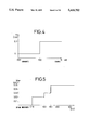
- FIG. 5 is an explanatory graph depicting exemplary values of a wiper driving load, which are used to set the standard load value by the vehicle electrical-load limiting apparatus;
- FIG. 6 is a graph showing a membership function of the deviation indicative of the difference between values of electrical loads, which is employed in a fuzzy inference executed by the vehicle electrical-load limiting apparatus;
- FIG. 7 is a graph showing a membership function of the remaining capacity, which is employed in the fuzzy inference executed by the vehicle electrical-load limiting apparatus;
- FIG. 8 is a graph showing a membership function of the amount of drive restriction of an electrical load, which is employed in the fuzzy inference executed by the vehicle electrical-load limiting apparatus;
- FIGS. 9(a) through 9(f) are graphs for describing the results of the fuzzy inference with respect to respective fuzzy control rules
- FIGS. 10(a) through 10(e) are graphs for describing the results of the fuzzy inference with respect to respective fuzzy control rules.
- FIG. 11 is a diagram showing an exemplary fuzzy relation of the amount of the drive restriction with respect to the deviation and the remaining capacity in the form of a three-dimensional coordinate table.
- a vehicle electrical-load limiting or restricting apparatus basically comprises an arithmetic device 5 for calculating the amount P of drive restriction of an electrical load in response to a detected signal W output from a load-condition detecting device 2 for detecting the state or condition of an electrical load 1 corresponding to each of various electrical equipment or components mounted on an electric vehicle and a detected signal E output from a residual-capacity detecting device 4 for detecting the amount of residual energy, i.e., residual capacity of an electric source 3 such as a battery for the electric vehicle, and a load control device 6 for controlling the driving of each of the electrical components in accordance with the output (the amount of drive restriction of the electrical load) P calculated by the arithmetic device 5.
- an arithmetic device 5 for calculating the amount P of drive restriction of an electrical load in response to a detected signal W output from a load-condition detecting device 2 for detecting the state or condition of an electrical load 1 corresponding to each of various electrical equipment or components mounted on an electric vehicle and a detected signal E output from
- the arithmetic device 5 also receives a detected signal output from a use environment sensor 7 used when a standard value of an electrical load is determined by considering use environments or conditions (such as ambient brightness, temperature and moisture on the road, etc. in case of an automobile, for example).
- a use environment sensor 7 used when a standard value of an electrical load is determined by considering use environments or conditions (such as ambient brightness, temperature and moisture on the road, etc. in case of an automobile, for example).
- a luminance sensor e.g., a raindrop or moisture sensor, and a temperature sensor.
- the vehicle electrical-load limiting apparatus is also provided with a display device 8 activated in response to a load control signal output from the load control device 6 in order to inform the state of the drive restriction of each of the electrical components (electrical loads) to a driver or the like.
- a display device 8 there is known a display element such as an LED, which represents which electrical component is restricted.
- the priority of the electrical components as to the restriction of the driving of the electrical components is determined in advance in order of importance of the electrical components mounted on the electric vehicle. Information about the priority thus determined is stored in the arithmetic device 5.
- the electrical components mounted on the electric vehicle can be divided into four groups, for example in order of their importance as follows:
- Blower motor heater coil
- condenser fan air conditioner
- Headlight H/L
- FR wiper H/L
- rear defroster fog light
- remocon (remote control) mirror auto antenna
- map light heated mirror
- passive belt courtesy light
- power door lock trunk light
- power sheet power sheet
- key light sunroof
- vanity mirror illumination audio, glove box light, cigar lighter.
- the A group in the above four groups is of a group which cannot be applied as objects subjected to the load restriction in view of safety, law or the like.
- the B group belongs to a group which can be applied as objects subjected to the load restriction and can adjust the amount of the drive restriction of each electrical load.
- the C group is of a group which can economically avoid the use of a corresponding electrical load when unnecessary in accordance with use environments or conditions (weather, day and night, speed, etc.) of a vehicle as well as with the residual capacity and the state of each of electrical loads. For example, a process for automatically putting out the light that a driver forgot to turn off after a vehicle has passed through a tunnel and an intermittent operation of a wiper at the time the driver waits for a traffic signal are included as objects.
- the D group is of a group which can be applied as objects subjected to the load restriction and cannot adjust the amount of the drive restriction of each electrical load. Now, the D group is further divided into two groups, i.e., D1 and D2 in the order of a high priority (importance).
- the detected signal W output from the load-condition detecting device 2 the residual capacity E of the electric source 3 output from the residual-capacity detecting device 4, the amount P of the drive restriction of the electrical load, and other values used for arithmetic operations are represented as follows:
- the standard value W B of the electrical load may be defined by setting the average value of electrical loads.
- the standard value W B can also be determined in the following manner. That is, the arithmetic device 5 first determines the use environments in response to the detected signal output from the use environment sensor 7 and then performs an automatic arithmetic operation or computation based on a predetermined algorithm in accordance with to the result of the determination, thereby making it possible to determine the standard value W B .
- the standard value W B can be calculated in accordance with the following equation, for example:
- W 0 the annual average value of electrical loads to be used, the average value of electrical loads used when it is fine during the day and the climate is in a calm season, or values [KW] varied with a change in season as shown in FIG. 2 are employed.
- W AC values which vary with temperature
- the temperature is detected by a temperature sensor mounted on a vehicle body.
- cold and warm temperatures may be determined based on an on/off state of an ON/OFF switch of an air-conditioner.
- W RL values which vary in two stages depending on the brightness and darkness, are used as W RL .
- the state of the brightness and darkness is detected by a luminance sensor attached to the vehicle body.
- the state of the brightness and darkness may be judged based on an on/off state of an ON/OFF switch of a headlight.
- W WP values which vary in a stepwise manner by the weather, are used as W WP .
- the weather (a change from fine weather to rainy weather) is detected from an output voltage [mV] of a moisture sensor mounted on the vehicle body.
- the weather may be determined by the output of a wiper drive sensor.
- control rules are defined as given in the next Table 1, for example. That is, the antecedent portion is used to determine at what degree the deviation e indicative of the difference between the values of the electrical loads and the residual capacity E are represented, whereas the consequent portion is used to determine at what degree the amount P of the drive restriction of the electrical load is represented.
- a plurality of control rules (49 rules in the present embodiment) are formulated in advance.
- PS Solid in positive direction
- the deviation e indicative of the difference between the values of the electrical loads, the residual capacity E of the electric source and the amount P of the drive restriction are respectively divided into the following fuzzy regions according to the above labels.
- the amount H 0 of operation corresponding to the present control state (e 0 , E 0 ) is obtained by firstly performing a min arithmetic operation on each of a plurality of rules and then performing a composite (max) arithmetic operation on the results of the min arithmetic operation. That is, the operation amount H 0 is calculated based on the following equation:
- the driving of the electrical loads (electric components) classified into the respective groups as described above can be restricted in accordance with the definitive value (the amount of the drive restriction) P 0 thus determined.
- a fuzzy relation of P to the above values e and E can be represented in the form of a three-dimensional coordinate table as shown in FIG. 11, for example.
- the fuzzy inference can rapidly be carried out by representing the fuzzy relation in the form of such a table and storing information about the table in a computer.
- the amount of the drive restriction of each of the electrical loads is determined by the two variables, i.e., the deviation e and the residual capacity E of the electric source with respect to the standard value W B of the electrical load as described above in the present invention. Therefore, the hunting is hard to occur. In order to reliably remove the hunting, a dead or neutral zone may be provided.
- the above embodiment describes a case in which the vehicle electrical-load limiting apparatus is employed in the electric vehicle.
- the present invention is not necessarily limited to the present embodiment.
- the apparatus may also be used as an apparatus for controlling electrical loads mounted on vehicles such as a hybrid-type electric automobile and an engine-driven type automobile each of which having an electric source such as a battery mounted thereon.
- the fuzzy inference is carried out by making use of the membership functions corresponding to both of the deviation indicative of the difference between the standard value set for each electrical load attached to the vehicle and the value of the electrical load when now in use and the residual capacity of the electric source. Thereafter, the amount of the drive restriction of each electrical load is obtained from the result of the fuzzy inference. It is therefore possible to automatically determine to what degree the driving of the electrical loads should be restricted according to the degree of the residual capacity of the electric source.
- the standard value of the electrical load can automatically be calculated depending on a present vehicle use environment, and the amount of the drive restriction of each electrical load can be judged based on the two values, i.e., the deviation indicative of the difference between the calculated standard value and the present value, and the residual capacity of the electric source, thereby making it possible to realize a further suitable and fine drive restriction.
Abstract
A vehicle electrical-load limiting apparatus wherein the priority given over a plurality of electrical loads, for restricting the driving of the electrical loads mounted on a vehicle, is first decided in order of importance and the amount of drive restriction of each of the electrical loads is then determined based on the remaining capacity of a vehicle electric source, thereby restricting the driving of the electrical loads. A fuzzy inference is carried out by making use of membership functions corresponding to both (a) the deviation indicative of the difference between a standard value set for each electrical load attached to the vehicle and a value of an electrical load when now in use, and (b) the residual capacity of the electric source. Then, the amount of the drive restriction of each of the electrical loads is obtained from the result of the fuzzy inference. It is therefore possible to automatically determine to what degree the driving of the electrical loads should be restricted according to the degree of the residual capacity of the electric source.
Description
1. Field of the Invention
The present invention relates to a vehicle electrical-load limiting apparatus for restricting, as needed, the driving of each of a plurality of electrical loads which are employed in a vehicle having an electric source mounted thereon such as a battery whose residual capacity is reduced with the elapse of time or a generator which needs another driving energy, and particularly employed in an electric automobile free of an internal combustion engine serving as a power source for its running or a hybrid-type electric automobile.
2. Description of the Related Art
In an electric vehicle having an electric motor serving as a power source, for example, the running distance is influenced by the residual capacity of a battery serving as an electric source for driving the electric motor. Therefore, there has been a demand for a battery having a capacity which can be increased as much as possible under conditions required for the electric vehicle. However, a battery capable of sufficiently providing, at one charge level, a running speed and a travelling distance of the electric vehicle, which are not inferior to those of a conventional engine-driven type automobile, has not yet been put to practical use. Even when a generator is mounted on a vehicle, it is important to ensure electrical energy for stably driving the generator for a predetermined period of time or longer.
Therefore, a technique for restricting the use of electrical loads, i.e., various electrical equipment or components mounted on a vehicle, which are activated by electrical energy supplied from an electric source mounted on the vehicle, in accordance with the conditions of the electric source, has been proposed with a view toward making a coverable or running distance longer by using an electric source such as a battery whose capacity is restricted.
In order to prevent an electric vehicle or the like from being incapable of reaching an intended place or a location at which a battery can be charged or replaced with another when the residual capacity of the vehicle battery is reduced, for example, there has been known a technique for restricting the driving of electrical components which are less important to the vehicle (or its driver) (see Japanese Utility Model Application Laid-Open Nos. 63-40135, 63-61360, for example). According to the disclosed technique, the electrical components (electrical loads) mounted on the vehicle are classified according to their importance. Priority given over the electrical components, for restricting the driving of the electrical components for each classification is then determined, and the groups of the electrical components whose driving is restricted are determined depending on the remaining capacity of the electric source mounted on the vehicle.
In the above disclosure, however, the driving of the electrical components is limited by quantitative restriction rules referred to as the classifications determined depending on the values of the residual capacity of the electric source. Therefore, a change in the classification of the electrical components whose driving is restricted occurs even if the values of the remaining capacity of the electric source vary slightly, so that inconvenience, i.e., unsuitable electrical load control such as a restriction beyond need, etc. tends to develop in practice. In order to perform the electrical load control suitable to practical use, it is necessary to judge or determine to what degree the driving of the electrical components should be restricted depending on how much the remaining capacity of the electric source is present and to carry out a fine drive restriction based on the result of the determination. The above disclosure has, however, the problem that the above determination and the drive restriction have not been taken into consideration.
It is therefore an object of the present invention to provide a vehicle electrical-load limiting apparatus capable of determining to what degree the driving of electrical loads should be restricted according to the remaining capacity of an electric source and of providing a fine drive restriction based on the result of the determination.
It is another object of the present invention to provide an apparatus for deciding priority given over a plurality of electrical loads, for restricting the driving of the electrical loads mounted on a vehicle in order of importance and determining the amount of drive restriction of each of the electrical loads on the basis of the remaining capacity of an electric source mounted on the vehicle, thereby restricting the driving of each of the electrical loads, the apparatus comprising arithmetic means for setting membership functions corresponding to both of the deviation indicative of the difference between a standard value set for each of the electrical loads and the present value indicative of the state of the present electrical load and the remaining capacity of the electric source and executing a fuzzy inference using the membership functions, thereby determining the amount of drive restriction of each of the electrical loads from the result of the execution of the fuzzy inference.
It is a further object of the present invention to provide a vehicle electrical-load limiting apparatus wherein the arithmetic means automatically calculates a standard value in accordance with an environmental state to which the vehicle is subjected.
It is a still further object of the present invention to provide a vehicle electrical-load limiting apparatus wherein an arithmetic operation on the environmental state is performed based on a detected signal output from each of a luminance sensor, a moisture sensor, and a temperature sensor.
It is a still further object of the present invention to provide a vehicle electrical-load limiting apparatus wherein the vehicle is an electric automobile.
It is a still further object of the present invention to provide a vehicle electrical-load limiting apparatus wherein the vehicle is a hybrid-type automobile.
It is a still further object of the present invention to provide a vehicle electrical-load limiting apparatus wherein the arithmetic means comprises restriction priority setting means for setting the drive restriction priority of the plurality of electrical loads mounted on the vehicle in order of importance, restriction priority storing means for storing therein the set drive restriction priority of the plurality of electrical loads, electrical load detecting means for detecting one of the plurality of electrical loads, standard value arithmetic means for performing an arithmetic operation on a standard value of a desired electrical load based on the present value of the detected one electrical load, deviation arithmetic means for calculating the deviation indicative of the difference between the present value of the detected one electrical load and the calculated standard value of the desired electrical load, residual-capacity detecting means for detecting the remaining capacity of an electric source mounted on the vehicle, fuzzy inference arithmetic means for reading a membership function of the deviation and the residual capacity, which has previously been stored in membership function storing means on the basis of the calculated deviation and the detected residual capacity and performing an arithmetic operation on a fuzzy inference based on the read membership function, amount-of-drive-restriction arithmetic means for calculating the amount 0f the drive restriction of each of the electrical loads from the result of the arithmetic operation on the fuzzy inference, and electrical-load controlling means for reading the drive restriction priority stored in the restriction priority storing means based on the result of the arithmetic operation on the amount of the drive restriction and controlling each of the electrical loads in accordance with the drive restriction priority.
It is a still further object of the present invention to provide a vehicle electrical-load limiting apparatus wherein the electrical loads whose drive restriction priority is stored in the restriction priority storing means are divided into a first group unsuitable to the drive restriction of the electrical loads, a second group capable of adjusting the amount of the drive restriction of each of the electrical loads, a third group capable of adjusting the amount of the drive restriction of each of the electrical loads and providing economical use of the electrical loads in accordance with use environments of the vehicle, and a fourth group suitable to the drive restriction of the electrical loads and incapable of adjusting the amount of the drive restriction of each of the electrical loads.
It is a still further object of the present invention to provide a vehicle electrical-load limiting apparatus wherein the first group includes electrical loads such as a power steering and a running-motor controller or the like, which are indispensable to the running of the vehicle.
It is a still further object of the present invention to provide a vehicle electrical-load limiting apparatus wherein the second group includes electrical loads such as an air conditioner and a heater coil or the like, which are capable of restricting performance of the electrical loads by reducing electric power to be supplied.
It is a still further object of the present invention to provide a vehicle electrical-load limiting apparatus wherein the third group includes electrical loads capable of restricting their performance by reducing supply power, and economically avoiding unnecessary operations such as wiper driving at the time of stoppage of the vehicle and control of the turning on of a headlight at a bright location.
It is a still further object of the present invention to provide a vehicle electrical-load limiting apparatus wherein the fourth group includes electrical loads such as an interior light and a remocon (remote control) mirror or the like, which are incapable of adjusting the amount of the drive restriction of each of the electrical loads when they are subjected to a use limit.
It is a still further object of the present invention to provide a vehicle electrical-load limiting apparatus wherein the use environments of the vehicle include the weather, the brightness and darkness.
It is a still further object of the present invention to provide a vehicle electrical-load limiting apparatus wherein the electrical load detecting means is a detecting circuit for detecting the total dissipated power of various electrical components mounted on the vehicle.
It is a still further object of the present invention to provide a vehicle electrical-load limiting apparatus wherein the standard value arithmetic means performs an arithmetic operation on a standard value of each electrical load based on the final standard load value, the average value of normal electrical loads necessary for vehicle running and each of coefficients of electrical loads of the heater and the air conditioner, an electrical load of the headlight and an electrical load for driving the wipers.
It is a still further object of the present invention to provide a vehicle electrical-load limiting apparatus wherein the residual-capacity detecting means includes depth-of-discharge detector for detecting the depth of discharge of a vehicle driving battery and an arithmetic circuit for calculating the remaining capacity of the battery based on the detected depth of discharge.
It is a still further object of the present invention to provide a vehicle electrical-load limiting apparatus wherein the fuzzy inference arithmetic means has a membership function storing circuit for storing therein a membership function of the deviation and the residual capacity which have been set in advance.
It is a still further object of the present invention to provide a vehicle electrical-load limiting apparatus wherein the fuzzy inference arithmetic means is activated to divide a membership function relative to the residual capacity read from the membership function storing means into a plurality of fuzzy regions in accordance with the depth of the discharge.
It is a still further object of the present invention to provide a vehicle electrical-load limiting apparatus wherein the amount-of-drive-restriction arithmetic means performs an arithmetic operation on the amount of the drive restriction based on the similarity of factors relative to the deviation and the similarity of factors relative to the residual capacity.
The above and other objects, features and advantages of the present invention will become apparent from the following description and the appended claims, taken in conjunction with the accompanying drawings in which a preferred embodiment of the present invention is shown by way of illustrative example.
FIG. 1 is a block diagram showing the structure of a vehicle electrical-load limiting apparatus according to one embodiment of the present invention;
FIG. 2 is an explanatory graph illustrating the average value of normal electrical loads, which is used to set a standard load value by the vehicle electrical-load limiting apparatus;
FIG. 3 is an explanatory graph showing exemplary values of electrical loads of a heater and an air-conditioner, which are used to set the standard load value by the vehicle electrical-load limiting apparatus;
FIG. 4 is an explanatory graph showing exemplary values of an electrical load of a headlight, which are used to set the standard load value by the vehicle electrical-load limiting apparatus;
FIG. 5 is an explanatory graph depicting exemplary values of a wiper driving load, which are used to set the standard load value by the vehicle electrical-load limiting apparatus;
FIG. 6 is a graph showing a membership function of the deviation indicative of the difference between values of electrical loads, which is employed in a fuzzy inference executed by the vehicle electrical-load limiting apparatus;
FIG. 7 is a graph showing a membership function of the remaining capacity, which is employed in the fuzzy inference executed by the vehicle electrical-load limiting apparatus;
FIG. 8 is a graph showing a membership function of the amount of drive restriction of an electrical load, which is employed in the fuzzy inference executed by the vehicle electrical-load limiting apparatus;
FIGS. 9(a) through 9(f) are graphs for describing the results of the fuzzy inference with respect to respective fuzzy control rules;
FIGS. 10(a) through 10(e) are graphs for describing the results of the fuzzy inference with respect to respective fuzzy control rules; and
FIG. 11 is a diagram showing an exemplary fuzzy relation of the amount of the drive restriction with respect to the deviation and the remaining capacity in the form of a three-dimensional coordinate table.
A vehicle electrical-load limiting or restricting apparatus according to one embodiment of the present invention basically comprises an arithmetic device 5 for calculating the amount P of drive restriction of an electrical load in response to a detected signal W output from a load-condition detecting device 2 for detecting the state or condition of an electrical load 1 corresponding to each of various electrical equipment or components mounted on an electric vehicle and a detected signal E output from a residual-capacity detecting device 4 for detecting the amount of residual energy, i.e., residual capacity of an electric source 3 such as a battery for the electric vehicle, and a load control device 6 for controlling the driving of each of the electrical components in accordance with the output (the amount of drive restriction of the electrical load) P calculated by the arithmetic device 5.
As will be described later, the arithmetic device 5 also receives a detected signal output from a use environment sensor 7 used when a standard value of an electrical load is determined by considering use environments or conditions (such as ambient brightness, temperature and moisture on the road, etc. in case of an automobile, for example). As such a sensor, there are known a luminance sensor, a raindrop or moisture sensor, and a temperature sensor.
The vehicle electrical-load limiting apparatus is also provided with a display device 8 activated in response to a load control signal output from the load control device 6 in order to inform the state of the drive restriction of each of the electrical components (electrical loads) to a driver or the like. As the display device 8, there is known a display element such as an LED, which represents which electrical component is restricted.
In various electrical components each serving as an electrical load 1, the priority of the electrical components as to the restriction of the driving of the electrical components is determined in advance in order of importance of the electrical components mounted on the electric vehicle. Information about the priority thus determined is stored in the arithmetic device 5.
The electrical components mounted on the electric vehicle can be divided into four groups, for example in order of their importance as follows:
A Group (unable to restrict)
Hazard, high-mount stop lamp, power brake stop light, tail light, power steering, turn light, position light, motor controller, back light, antilock brake, regenerative energy system, license lamp, air bag, horn, side marker, meter and the like, reverse chime, transmission controller, heater unit, washing liquid, power window, radio, cooling fan, watch, mode motor
B Group (performance restriction)
Blower motor, heater coil, condenser fan, air conditioner
C Group (load saving)
Headlight (H/L), FR wiper (H/L), rear defroster, fog light
D Group (able to restrict)
Interior light, remocon (remote control) mirror, auto antenna, map light, heated mirror, passive belt, courtesy light, power door lock, trunk light, power sheet, key light, sunroof, vanity mirror, illumination audio, glove box light, cigar lighter.
The A group in the above four groups is of a group which cannot be applied as objects subjected to the load restriction in view of safety, law or the like.
The B group belongs to a group which can be applied as objects subjected to the load restriction and can adjust the amount of the drive restriction of each electrical load.
The C group is of a group which can economically avoid the use of a corresponding electrical load when unnecessary in accordance with use environments or conditions (weather, day and night, speed, etc.) of a vehicle as well as with the residual capacity and the state of each of electrical loads. For example, a process for automatically putting out the light that a driver forgot to turn off after a vehicle has passed through a tunnel and an intermittent operation of a wiper at the time the driver waits for a traffic signal are included as objects.
The D group is of a group which can be applied as objects subjected to the load restriction and cannot adjust the amount of the drive restriction of each electrical load. Now, the D group is further divided into two groups, i.e., D1 and D2 in the order of a high priority (importance).
A description will now be made of one example illustrative of a load control algorithm executed by a fuzzy inference in the arithmetic device 5.
According to the arrangement shown in FIG. 1, the detected signal W output from the load-condition detecting device 2, the residual capacity E of the electric source 3 output from the residual-capacity detecting device 4, the amount P of the drive restriction of the electrical load, and other values used for arithmetic operations are represented as follows:
Standard value of electrical load: WB [W]
Present value of electrical load: W [W]
Deviation indicative of difference between values of electrical loads: e=WB -W [W]
Residual capacity of electric source: E [Wh]
Amount of drive restriction of electrical load: P [W]
The standard value WB of the electrical load may be defined by setting the average value of electrical loads. However, the standard value WB can also be determined in the following manner. That is, the arithmetic device 5 first determines the use environments in response to the detected signal output from the use environment sensor 7 and then performs an automatic arithmetic operation or computation based on a predetermined algorithm in accordance with to the result of the determination, thereby making it possible to determine the standard value WB. in this case, the standard value WB can be calculated in accordance with the following equation, for example:
W.sub.B =W.sub.0 k.sub.1 W.sub.AC +k.sub.2 W.sub.HL +k.sub.3 W.sub.WP(1)
where
WB : final standard load value
W0 : average value of normal electrical loads necessary for vehicle running
WAC : electrical load of heater/air-conditioner
WHL : electrical load of headlight
WWP : wiper driving load
k1, k2, k3 : coefficients of respective electrical loads
As W0 referred to above, the annual average value of electrical loads to be used, the average value of electrical loads used when it is fine during the day and the climate is in a calm season, or values [KW] varied with a change in season as shown in FIG. 2 are employed.
As illustrated in FIG. 3, values which vary with temperature, are used as WAC. The temperature is detected by a temperature sensor mounted on a vehicle body. Alternatively, cold and warm temperatures may be determined based on an on/off state of an ON/OFF switch of an air-conditioner.
As shown in FIG. 4, values which vary in two stages depending on the brightness and darkness, are used as WRL. The state of the brightness and darkness is detected by a luminance sensor attached to the vehicle body. Alternatively, the state of the brightness and darkness may be judged based on an on/off state of an ON/OFF switch of a headlight.
As illustrated in FIG. 5, values which vary in a stepwise manner by the weather, are used as WWP. The weather (a change from fine weather to rainy weather) is detected from an output voltage [mV] of a moisture sensor mounted on the vehicle body. Alternatively, the weather may be determined by the output of a wiper drive sensor.
According to the present invention, control rules are defined as given in the next Table 1, for example. That is, the antecedent portion is used to determine at what degree the deviation e indicative of the difference between the values of the electrical loads and the residual capacity E are represented, whereas the consequent portion is used to determine at what degree the amount P of the drive restriction of the electrical load is represented. A plurality of control rules (49 rules in the present embodiment) are formulated in advance.
              TABLE 1
______________________________________
E e   NB      NM      NS    ZO    PS    PM    PB
______________________________________
NB    (1)     (8)     (15)  (22)  (29)  (36)  (43)
      NB      NB      NB    NB    NB    NB    NB
NM    (2)     (9)     (16)  (23)  (30)  (37)  (44)
      NB      NM      NM    NM    NM    NM    NM
NS    (3)     (10)    (17)  (24)  (31)  (38)  (45)
      NM      NM      NM    NS    NS    NS    NS
ZO    (4)     (11)    (18)  (25)  (32)  (39)  (46)
      NM      NS      ZO    ZO    ZO    ZO    ZO
PS    (5)     (12)    (19)  (26)  (33)  (40)  (47)
      NS      ZO      ZO    ZO    ZO    PS    PS
PM    (6)     (13)    (20)  (27)  (34)  (41)  (48)
      PM      PM      PM    PM    PM    PM    PM
PB    (7)     (14)    (21)  (28)  (35)  (42)  (49)
      PB      PB      PB    PB    PB    PB    PB
______________________________________
Incidentally, fuzzy labels given in Table 1 are as follows:
PB (Positive Big): large in positive direction
PM (Positive Medium): medium in positive direction
PS (Positive Small): small in positive direction
ZO (Zero): substantially zero
NS (Negative Small): small in negative direction
NM (Negative Medium): medium in negative direction
NB (Negative Big): large in negative direction
Numerals given in parentheses in Table 1 show rules' numbers.
The deviation e indicative of the difference between the values of the electrical loads, the residual capacity E of the electric source and the amount P of the drive restriction are respectively divided into the following fuzzy regions according to the above labels.
              TABLE 2
______________________________________
 ##STR1##
 ##STR2##
______________________________________
              TABLE 3
______________________________________
         ##STR3##
______________________________________
         where DOD represents the depth of discharge.
              TABLE 4
______________________________________
 ##STR4##
 ##STR5##
______________________________________
Membership functions corresponding to the deviation e indicative of the difference between the values of the electrical loads, the residual capacity E of the electric source and the amount P of the drive restriction of the electrical load are defined as illustrated in FIGS. 6 through 8, respectively.
Thus, the amount H0 of operation corresponding to the present control state (e0, E0) is obtained by firstly performing a min arithmetic operation on each of a plurality of rules and then performing a composite (max) arithmetic operation on the results of the min arithmetic operation. That is, the operation amount H0 is calculated based on the following equation:
H.sub.0 =max{f.sub.i (e.sub.0)Λg.sub.i (E.sub.0)ΛP.sub.i (P)}(2)
where i=1, 2, 3, . . . , 49 (numbers of rules).
When the deviation e and the residual capacity E are respectively e0 and E0 shown in the drawing, for example, the similarity of factors, i.e., membership values relative to the deviation e are represented as NB=0, NM=0.3, NS=1.0, ZO=0.3, PS=PM=PB=0, respectively. Membership values relative to the residual capacity E are represented as NB=0.1, NM=0.9, NS=0.5, ZO=PS=PM=PB=0, respectively. The amount P of the drive restriction obtained for each rule is represented by an area (fuzzy set) indicated by oblique lines shown in each of FIGS. 9 and 10. H0 calculated from the equation (2) is equivalent to a synthesized or combined fuzzy quantity represented by a membership function as illustrated in FIG. 10(e). Therefore, the center of gravity G is now calculated from the following equation (3) in accordance with a center-of-gravity method so as to determine it as a definitive value P0. ##EQU1##
The driving of the electrical loads (electric components) classified into the respective groups as described above can be restricted in accordance with the definitive value (the amount of the drive restriction) P0 thus determined.
In addition, a fuzzy relation of P to the above values e and E can be represented in the form of a three-dimensional coordinate table as shown in FIG. 11, for example. The fuzzy inference can rapidly be carried out by representing the fuzzy relation in the form of such a table and storing information about the table in a computer.
When the driving of each of the electrical loads is limited by a predetermined value, there is a possibility of hunting being produced. However, the amount of the drive restriction of each of the electrical loads is determined by the two variables, i.e., the deviation e and the residual capacity E of the electric source with respect to the standard value WB of the electrical load as described above in the present invention. Therefore, the hunting is hard to occur. In order to reliably remove the hunting, a dead or neutral zone may be provided.
The above embodiment describes a case in which the vehicle electrical-load limiting apparatus is employed in the electric vehicle. However, the present invention is not necessarily limited to the present embodiment. The apparatus may also be used as an apparatus for controlling electrical loads mounted on vehicles such as a hybrid-type electric automobile and an engine-driven type automobile each of which having an electric source such as a battery mounted thereon.
According to the present invention, as described above, the fuzzy inference is carried out by making use of the membership functions corresponding to both of the deviation indicative of the difference between the standard value set for each electrical load attached to the vehicle and the value of the electrical load when now in use and the residual capacity of the electric source. Thereafter, the amount of the drive restriction of each electrical load is obtained from the result of the fuzzy inference. It is therefore possible to automatically determine to what degree the driving of the electrical loads should be restricted according to the degree of the residual capacity of the electric source.
Further, the standard value of the electrical load can automatically be calculated depending on a present vehicle use environment, and the amount of the drive restriction of each electrical load can be judged based on the two values, i.e., the deviation indicative of the difference between the calculated standard value and the present value, and the residual capacity of the electric source, thereby making it possible to realize a further suitable and fine drive restriction.
Having now fully described the intention, it will be apparent to those skilled in the art that many changes and modifications can be made without departing from the spirit or scope of the invention as set forth herein.
Claims (17)
1. An apparatus, for deciding priority given over a plurality of electrical loads and restricting the driving of said electrical loads mounted on an electric vehicle in order of importance and determining the amount of drive restriction of each of said electrical loads on the basis of the remaining capacity of an electric source mounted on the electric vehicle, thereby restricting the driving of each of said electrical loads, said apparatus comprising:
arithmetic means for setting membership functions corresponding to both (1) a deviation indicative of the difference between a standard value set for each of said electrical loads and a present value indicative of the state of the present electrical load and (2) the remaining capacity of said electric source and executing a fuzzy inference using said membership functions, thereby determining the amount of the drive restriction of each of said electrical loads from the result of the execution of said fuzzy inference;
wherein said arithmetic means comprises:
(a) restriction priority setting means for setting said drive restriction priority of said plurality of electrical loads mounted on the vehicle in order of importance;
(b) restriction priority storing means for storing therein said set drive restriction priority of said plurality of electrical loads;
(c) electrical load detecting means for detecting one of said plurality of electrical loads;
(d) standard value arithmetic means for performing an arithmetic operation on a standard value of a desired electrical load based on the present value of said detected one electrical load;
(e) deviation arithmetic means for calculating the deviation indicative of the difference between the present value of said detected one electrical load and said calculated standard value of said desired electrical load;
(f) residual-capacity detecting means for detecting the remaining capacity of an electric source mounted on the vehicle;
(g) fuzzy inference arithmetic means for reading a membership function of the deviation and the residual capacity, which has previously been stored in membership function storing means on the basis of said calculated deviation and said detected residual capacity and performing an arithmetic operation on a fuzzy inference based on said read membership function;
(h) amount-of-drive-restriction arithmetic means for calculating the amount of the drive restriction of each of said electrical loads from the result of the arithmetic operation on said fuzzy inference; and
(i) electrical-load controlling means for reading said drive restriction priority stored in said restriction priority storing means based on the result of the arithmetic operation on said amount of the drive restriction and controlling each of said electrical loads in accordance with said drive restriction priority; and
wherein said electrical loads whose drive restriction priority is stored in said restriction priority storing means are divided into a first group unsuitable to the drive restriction of said electrical loads, a second group capable of adjusting the amount of the drive restriction of each of said electrical loads, a third group capable of adjusting the amount of the drive restriction of each of said electrical loads and providing economical use of said electrical loads in accordance with use environments of the vehicle, and a fourth group suitable to the drive restriction of said electrical loads and incapable of adjusting the amount of the drive restriction of each of said electrical loads.
2. An apparatus according to claim 1, wherein said first group includes electrical loads such as a power steering and a running-motor controller or the like, which are indispensable to the running of the vehicle.
3. An apparatus according to claim 1, wherein said second group includes electrical loads such as an air conditioner and a heater coil or the like, which are capable of restricting performance of said electrical loads by reducing electric power to be supplied.
4. An apparatus according to claim 1, wherein said third group includes electrical loads capable of restricting their performance by reducing supply power, and economically avoiding unnecessary operations such as wiper driving at the time of stoppage of the vehicle and control of the turning on of a headlight at a bright location.
5. An apparatus according to claim 1, wherein said fourth group includes electrical loads such as an interior light and a remocon mirror or the like, which are incapable of adjusting the amount of the drive restriction of each of said electrical loads when they are subjected to a use limit.
6. An apparatus according to claim 1, wherein said electrical load detecting means is a detecting circuit for detecting the total dissipated power of various electrical components mounted on the vehicle.
7. An apparatus according to claim 1, wherein said residual-capacity detecting means includes depth-of-discharge detector for detecting the depth of discharge of a vehicle driving battery and an arithmetic circuit for calculating the remaining capacity of the battery based on said detected depth of discharge.
8. An apparatus according to claim 1, wherein said fuzzy inference arithmetic means has a membership function storing circuit for storing therein a membership function of the deviation and the residual capacity which have been set in advance.
9. An apparatus according to claim 1, wherein said fuzzy inference arithmetic means is activated to divide a membership function relative to the residual capacity read from said membership function storing means into a plurality of fuzzy regions in accordance with the depth of the discharge.
10. An apparatus according to claim 1, wherein said amount-of-drive-restriction arithmetic means performs an arithmetic operation on the amount of the drive restriction based on values of the membership functions relative to the deviation and values of the membership functions relative to the residual capacity.
11. An apparatus according to claim 1, wherein said arithmetic means automatically calculates a standard value in accordance with an environmental state to which the vehicle is subjected.
12. An apparatus according to claim 11, wherein an arithmetic operation on said environmental state is performed based on a detected signal output from each of a luminance sensor, a moisture sensor and a temperature sensor.
13. An apparatus according to claim 1, wherein said vehicle is an electric automobile.
14. An apparatus, for deciding priority given over a plurality of electrical loads for restricting the driving of said electrical loads mounted on a vehicle in order of importance and determining the amount of drive restriction of each of said electrical loads on the basis of the remaining capacity of an electric source mounted on the vehicle, thereby restricting the driving of each of said electrical loads, said apparatus comprising:
arithmetic means for setting membership functions corresponding to both the deviation indicative of the difference between a standard value set for each of said electrical loads and the present value indicative of the state of the present electrical load and the remaining capacity of said electric source, and executing a fuzzy inference using said membership functions, thereby determining the amount of the drive restriction of each of said electrical loads from the result of the execution of said fuzzy inference;
said arithmetic means comprising restriction priority setting means for setting said drive restriction priority of said plurality of electrical loads mounted on the vehicle in order of importance, restriction priority storing means for storing therein said set drive restriction priority of said plurality of electrical loads, electrical load detecting means for detecting one of said plurality of electrical loads, standard value arithmetic means for performing an arithmetic operation on a standard value of a desired electrical load based on the present value of said detected one electrical loads, deviation arithmetic means for calculating the deviation indicative of the difference between the present value of said detected one electrical load and said calculated standard value of said desired electrical load, residual-capacity detecting means for detecting the remaining capacity of an electric source mounted on the vehicle, fuzzy inference arithmetic means for reading a membership function of the deviation and the residual capacity, which as previously been stored in membership function storing means on the basis of said calculated deviation and said detected residual capacity and performing an arithmetic operation on a fuzzy inference based on said read membership function, amount-of-drive-restriction arithmetic means for calculating the amount of the drive restriction of each of said electrical loads from the result of the arithmetic operation on said fuzzy inference, and electrical-load controlling means for reading said drive restriction priority stored in said restriction priority storing means based on the result of the arithmetic operation on said amount of the drive restriction and controlling each of said electrical loads in accordance with said drive restriction priority; and
wherein said standard value arithmetic means performs an arithmetic operation on a standard value of each electrical load based on the final standard load value, the average value of normal electrical loads necessary for vehicle running and each of coefficients of electrical loads of the heater and the air conditioner, an electrical load of the headlight and an electrical load for driving the wipers.
15. An apparatus according to claim 14, wherein said arithmetic means automatically calculates a standard value in accordance with an environmental state to which the vehicle is subjected.
16. An apparatus according to claim 15, wherein an arithmetic operation on said environmental state is performed based on a detected signal output from each of a luminance sensor, a moisture sensor, and a temperature sensor.
17. An apparatus according to claim 14, wherein said vehicle is an electric automobile.
Applications Claiming Priority (2)
| Application Number | Priority Date | Filing Date | Title |
|---|---|---|---|
| JP3-117699 | 1991-05-22 | ||
| JP3117699A JPH04347536A (en) | 1991-05-22 | 1991-05-22 | Electric load limiter for vehicle |
Publications (1)
| Publication Number | Publication Date |
|---|---|
| US5416702A true US5416702A (en) | 1995-05-16 |
Family
ID=14718119
Family Applications (1)
| Application Number | Title | Priority Date | Filing Date |
|---|---|---|---|
| US07/884,525 Expired - Lifetime US5416702A (en) | 1991-05-22 | 1992-05-15 | Vehicle electrical-load limiting apparatus |
Country Status (2)
| Country | Link |
|---|---|
| US (1) | US5416702A (en) |
| JP (1) | JPH04347536A (en) |
Cited By (78)
| Publication number | Priority date | Publication date | Assignee | Title |
|---|---|---|---|---|
| US5473228A (en) * | 1993-10-07 | 1995-12-05 | Toyota Jidosha Kabushiki Kaisha | Control method for electrical appliance in hybrid vehicle |
| US5642250A (en) * | 1992-09-14 | 1997-06-24 | Siemens Aktiengesellschaft | Protection release method |
| EP0812965A1 (en) * | 1996-06-13 | 1997-12-17 | KABUSHIKI KAISHA KOBE SEIKO SHO also known as Kobe Steel Ltd. | Battery-driven working machine |
| US5714866A (en) * | 1994-09-08 | 1998-02-03 | National Semiconductor Corporation | Method and apparatus for fast battery charging using neural network fuzzy logic based control |
| US5722911A (en) * | 1995-07-24 | 1998-03-03 | Toyota Jidoshi Kabushiki Kaisha | Vehicle control apparatus adapted to charge energy storage device by generator driven by surplus engine power which changes with required vehicle drive force |
| WO1998040949A1 (en) * | 1997-03-13 | 1998-09-17 | Robert Bosch Gmbh | Circuit for supplying a consumer with electric energy |
| US5845221A (en) * | 1995-06-30 | 1998-12-01 | Yazaki Corporation | Load control system for vehicle |
| FR2772684A1 (en) * | 1997-12-22 | 1999-06-25 | Renault | Power regulation in electric vehicle transmission keeping total distance within battery capability and not significantly limiting starting torque |
| US5925997A (en) * | 1997-07-22 | 1999-07-20 | Honda Giken Kogyo Kabushiki Kaisha | Drive circuit system for power window |
| US6055479A (en) * | 1998-04-15 | 2000-04-25 | Magellan Dis, Inc. | Vehicle navigation system with improved powerup performance |
| EP0888960A3 (en) * | 1997-07-03 | 2000-07-05 | Honda Giken Kogyo Kabushiki Kaisha | Electric power supply control apparatus for a motor assist vehicle |
| US6452286B1 (en) * | 1999-09-02 | 2002-09-17 | Nissan Motor Co., Ltd. | Control device of a hybrid vehicle |
| WO2003012952A1 (en) * | 2001-07-21 | 2003-02-13 | Bayerische Motoren Werke | Method and device for controlling the charging of a motor vehicle battery |
| US20030158635A1 (en) * | 1999-07-30 | 2003-08-21 | Oshkosh Truck Corporation | Firefighting vehicle with network-assisted scene management |
| US20030158638A1 (en) * | 1999-07-30 | 2003-08-21 | Oshkosh Truck Corporation | Control system and method for electric vehicle |
| US20030158640A1 (en) * | 1999-07-30 | 2003-08-21 | Oshkosh Truck Corporation | Equipment service vehicle with network-assisted vehicle service and repair |
| US20030163229A1 (en) * | 1999-07-30 | 2003-08-28 | Oshkosh Truck Corporation | Turret envelope control system and method for a fire fighting vehicle |
| US20030195680A1 (en) * | 2000-02-09 | 2003-10-16 | Oshkosh Truck Corporation | Equipment service vehicle having on-board diagnostic system |
| US20040002794A1 (en) * | 1999-07-30 | 2004-01-01 | Oshkosh Truck Corporation | Steering control system and method |
| US20040019414A1 (en) * | 1999-07-30 | 2004-01-29 | Oshkosh Truck Corporation | Vehicle control system and method |
| US20040039510A1 (en) * | 1999-07-30 | 2004-02-26 | Oshkosh Truck Corporation | Control system and method for an equipment service vehicle |
| US6700386B2 (en) * | 2000-12-28 | 2004-03-02 | Denso Corporation | Power distribution apparatus for a motor vehicle |
| US20040055802A1 (en) * | 2002-08-02 | 2004-03-25 | Oshkosh Truck Corporation | Refuse vehicle control system and method |
| US6718214B1 (en) * | 1998-12-15 | 2004-04-06 | Robert Bosch Gmbh | Method for switching consumer on or off |
| US20040104570A1 (en) * | 1997-12-16 | 2004-06-03 | Nsk Autoliv Co., Ltd. | Automotive passenger restraint and protection apparatus |
| US20040124703A1 (en) * | 2002-10-15 | 2004-07-01 | Denso Corporation | Method and apparatus for driving and controlling on-vehicle loads |
| US20040133319A1 (en) * | 1999-07-30 | 2004-07-08 | Oshkosh Truck Corporation | User interface and method for vehicle control system |
| US20040239184A1 (en) * | 2001-08-30 | 2004-12-02 | Stefan Brosig | Method and device for stabilizing an on-board electrical system of a vehicle electrical system |
| US20050113996A1 (en) * | 2001-12-21 | 2005-05-26 | Oshkosh Truck Corporation | Ambulance control system and method |
| US20050114007A1 (en) * | 2001-12-21 | 2005-05-26 | Oshkosh Truck Corporation | Multi-network control system for a vehicle |
| US20050113988A1 (en) * | 2001-12-21 | 2005-05-26 | Oshkosh Truck Corporation | Failure mode operation for an electric vehicle |
| US20050275289A1 (en) * | 2004-06-14 | 2005-12-15 | Shadi Jabaji | System and method for electrical energy switching and control in a vehicle |
| US7024296B2 (en) * | 1999-07-30 | 2006-04-04 | Oshkosh Truck Corporation | Control system and method for an equipment service vehicle |
| EP1650863A1 (en) * | 2004-10-22 | 2006-04-26 | Favess Co., Ltd. | Electric power steering apparatus and electricity supply system |
| US7072745B2 (en) | 1999-07-30 | 2006-07-04 | Oshkosh Truck Corporation | Refuse vehicle control system and method |
| US7127331B2 (en) | 1999-07-30 | 2006-10-24 | Oshkosh Truck Corporation | Turret operator interface system and method for a fire fighting vehicle |
| US20060287775A1 (en) * | 2003-09-09 | 2006-12-21 | Siemens Aktiengesellschaft | Method for controlling a power flow |
| US20070005205A1 (en) * | 2005-06-30 | 2007-01-04 | Caterpillar Inc. | Method for operating an electrical system |
| US7162332B2 (en) | 1999-07-30 | 2007-01-09 | Oshkosh Truck Corporation | Turret deployment system and method for a fire fighting vehicle |
| US7184862B2 (en) | 1999-07-30 | 2007-02-27 | Oshkosh Truck Corporation | Turret targeting system and method for a fire fighting vehicle |
| US7184866B2 (en) | 1999-07-30 | 2007-02-27 | Oshkosh Truck Corporation | Equipment service vehicle with remote monitoring |
| US20070061054A1 (en) * | 2002-02-28 | 2007-03-15 | Oshkosh Truck Corporation | Turret positioning system and method for a vehicle |
| US20070059016A1 (en) * | 2005-09-12 | 2007-03-15 | Naoki Sato | Image forming apparatus |
| US20070152502A1 (en) * | 2005-11-18 | 2007-07-05 | Kinsey Gregory W | Power supply control system for a vehicle trailer |
| US20080224663A1 (en) * | 2007-03-14 | 2008-09-18 | Ford Global Technologies, Llc | Method and apparatus to control electric power consumption |
| US20090030610A1 (en) * | 2007-07-27 | 2009-01-29 | Magellan Navigation, Inc. | Supplemental powered information receiver |
| US20090123814A1 (en) * | 2007-10-09 | 2009-05-14 | Mason Cabot | Power source and method of managing a power source |
| US7536241B2 (en) * | 1997-10-07 | 2009-05-19 | Robert Bosch Gmbh | Control device for a system, and method for operating the control device |
| US20090140574A1 (en) * | 2007-11-30 | 2009-06-04 | Caterpillar Inc. | System and method for integrated power control |
| US20090261785A1 (en) * | 2008-03-27 | 2009-10-22 | Mason Cabot | Method for managing a modular power source |
| US20090263708A1 (en) * | 2008-04-02 | 2009-10-22 | Josh Bender | System and method of integrated thermal management for a multi-cell battery pack |
| US20090292454A1 (en) * | 2008-05-26 | 2009-11-26 | Jtekt Corporation | Vehicle control apparatus |
| US7711460B2 (en) | 2001-01-31 | 2010-05-04 | Oshkosh Corporation | Control system and method for electric vehicle |
| US20100127654A1 (en) * | 2008-11-25 | 2010-05-27 | Anderson Randall T | Machine control system and method |
| US20100133030A1 (en) * | 2008-11-20 | 2010-06-03 | Karl Johnson | Frame for a ride-on vehicle having a plurality of battery packs |
| US20100136405A1 (en) * | 2008-04-02 | 2010-06-03 | Karl Johnson | Battery pack with optimized mechanical, electrical, and thermal management |
| US7792618B2 (en) | 2001-12-21 | 2010-09-07 | Oshkosh Corporation | Control system and method for a concrete vehicle |
| US7835838B2 (en) | 1999-07-30 | 2010-11-16 | Oshkosh Corporation | Concrete placement vehicle control system and method |
| US7848857B2 (en) | 2001-01-31 | 2010-12-07 | Oshkosh Corporation | System and method for braking in an electric vehicle |
| WO2011003812A2 (en) | 2009-07-08 | 2011-01-13 | Cwa Constructions Sa | Aerial able car system having transportation operating equipment for passenger and/or freight transport |
| US20110144860A1 (en) * | 2009-12-14 | 2011-06-16 | Robert Bosch Gmbh | Electronic control module heat limiting systems and methods |
| FR2954864A1 (en) * | 2009-12-29 | 2011-07-01 | Renault Sa | DEVICE FOR DISTRIBUTING THE ELECTRIC ENERGY AVAILABLE IN A VEHICLE AND CORRESPONDING METHOD |
| US8139109B2 (en) | 2006-06-19 | 2012-03-20 | Oshkosh Corporation | Vision system for an autonomous vehicle |
| US8312954B2 (en) | 2010-04-22 | 2012-11-20 | Mission Motor Company | Frame for a two wheeled electric vehicle |
| US8540048B2 (en) | 2011-12-28 | 2013-09-24 | Caterpillar Inc. | System and method for controlling transmission based on variable pressure limit |
| US8793002B2 (en) | 2008-06-20 | 2014-07-29 | Caterpillar Inc. | Torque load control system and method |
| CN104184189A (en) * | 2014-08-15 | 2014-12-03 | 智慧城市系统服务(中国)有限公司 | Energy distribution method and energy distribution device |
| US8947531B2 (en) | 2006-06-19 | 2015-02-03 | Oshkosh Corporation | Vehicle diagnostics based on information communicated between vehicles |
| TWI513625B (en) * | 2011-03-31 | 2015-12-21 | 島野股份有限公司 | Bicycle component control apparatus |
| US9403528B2 (en) * | 2014-07-18 | 2016-08-02 | Ford Global Technologies, Llc | Method and assembly for directing power within an electrified vehicle |
| US20160229302A1 (en) * | 2015-02-06 | 2016-08-11 | Mando Corporation | Apparatus and method for power control |
| US20160316621A1 (en) * | 2015-04-29 | 2016-11-03 | Deere & Company | Energy management system for an agricultural vehicle arrangement |
| US9845191B2 (en) | 2013-08-02 | 2017-12-19 | Oshkosh Corporation | Ejector track for refuse vehicle |
| CN108099691A (en) * | 2016-11-25 | 2018-06-01 | 现代自动车株式会社 | For controlling the method and system of motor |
| US10065525B2 (en) * | 2013-08-06 | 2018-09-04 | Gogoro Inc. | Adjusting electric vehicle systems based on an electrical energy storage device thermal profile |
| CN109933025A (en) * | 2018-12-29 | 2019-06-25 | 丰疆智慧农业股份有限公司 | Intelligent agricultural machinery electric quantity managing method and power management system |
| US10596959B1 (en) * | 2018-10-04 | 2020-03-24 | Douglas Gary DeWalt | System and method for signaling vehicle speed and rapid deceleration utilizing tail lights |
| US20220399726A1 (en) * | 2017-11-02 | 2022-12-15 | Semiconductor Energy Laboratory Co., Ltd. | Power feeding device, electronic device, and operation method of power feeding device |
Families Citing this family (13)
| Publication number | Priority date | Publication date | Assignee | Title |
|---|---|---|---|---|
| JPH08322160A (en) * | 1995-05-24 | 1996-12-03 | Yamaha Motor Co Ltd | Overdischarging prevention unit for battery set |
| JP4031566B2 (en) * | 1998-02-23 | 2008-01-09 | 三菱重工業株式会社 | Control device for vehicle air conditioner |
| JP2000261982A (en) * | 1999-03-10 | 2000-09-22 | Toyota Motor Corp | Vehicle power supply controller |
| JP3549806B2 (en) | 2000-03-01 | 2004-08-04 | 株式会社日立製作所 | Automotive power supply controller |
| JP3888585B2 (en) * | 2002-10-15 | 2007-03-07 | 株式会社デンソー | Vehicle load drive control device |
| JP4490293B2 (en) * | 2005-01-05 | 2010-06-23 | 株式会社オートネットワーク技術研究所 | In-vehicle power saving device |
| JP2006347295A (en) * | 2005-06-14 | 2006-12-28 | Toyota Motor Corp | Control device of vehicle electrical load |
| US7692412B2 (en) | 2006-02-20 | 2010-04-06 | Fujitsu Ten Limited | Charging control apparatus, charging control method |
| JP5315977B2 (en) * | 2008-12-19 | 2013-10-16 | トヨタ自動車株式会社 | Vehicle heating system |
| JP5604975B2 (en) * | 2010-05-20 | 2014-10-15 | 株式会社オートネットワーク技術研究所 | Vehicle power supply control device |
| FR2962956B1 (en) * | 2010-07-26 | 2013-05-17 | Valeo Vision | CONTROL METHOD FOR VEHICLE PROJECTOR |
| WO2013183085A1 (en) * | 2012-06-06 | 2013-12-12 | 三菱電機株式会社 | Vehicle-mounted information apparatus |
| JP2014024417A (en) * | 2012-07-25 | 2014-02-06 | Auto Network Gijutsu Kenkyusho:Kk | Vehicle power source control device |
Citations (12)
| Publication number | Priority date | Publication date | Assignee | Title |
|---|---|---|---|---|
| US3891979A (en) * | 1972-11-07 | 1975-06-24 | Braun Otto P | Road condition monitoring devices |
| US4042056A (en) * | 1975-11-21 | 1977-08-16 | Automobile Corporation Of America | Hybrid powered automobile |
| US4222450A (en) * | 1978-04-13 | 1980-09-16 | Hiram Fobbs | Electrical drive for automobile |
| US4620283A (en) * | 1983-11-29 | 1986-10-28 | Lehigh University | Programmable load controller |
| JPS6340135A (en) * | 1986-08-06 | 1988-02-20 | Konica Corp | Color copying device having color tone adjusting means |
| JPS6361360A (en) * | 1986-09-02 | 1988-03-17 | Nec Corp | Inter-host job linking control system |
| US4809175A (en) * | 1986-08-06 | 1989-02-28 | Honda Giken Kogyo Kabushiki Kaisha | Vehicle control system and method therefor |
| US4916328A (en) * | 1988-12-08 | 1990-04-10 | Honeywell Inc. | Add/shed load control using anticipatory processes |
| US5124916A (en) * | 1989-08-24 | 1992-06-23 | Toyota Jidosha Kabushiki Kaisha | Apparatus for controlling vehicle automatic transmission according to fuzzy set theory |
| US5136209A (en) * | 1989-09-15 | 1992-08-04 | Benedict Engineering Company, Inc. | Vehicle light, windshield wiper control system |
| US5150045A (en) * | 1989-11-22 | 1992-09-22 | Fuji Jukogyo Kabushiki Kaisha | Electric automobile |
| US5166584A (en) * | 1990-07-05 | 1992-11-24 | Nissan Motor Co., Ltd. | Electric vehicle |
-
1991
- 1991-05-22 JP JP3117699A patent/JPH04347536A/en active Pending
-
1992
- 1992-05-15 US US07/884,525 patent/US5416702A/en not_active Expired - Lifetime
Patent Citations (12)
| Publication number | Priority date | Publication date | Assignee | Title |
|---|---|---|---|---|
| US3891979A (en) * | 1972-11-07 | 1975-06-24 | Braun Otto P | Road condition monitoring devices |
| US4042056A (en) * | 1975-11-21 | 1977-08-16 | Automobile Corporation Of America | Hybrid powered automobile |
| US4222450A (en) * | 1978-04-13 | 1980-09-16 | Hiram Fobbs | Electrical drive for automobile |
| US4620283A (en) * | 1983-11-29 | 1986-10-28 | Lehigh University | Programmable load controller |
| JPS6340135A (en) * | 1986-08-06 | 1988-02-20 | Konica Corp | Color copying device having color tone adjusting means |
| US4809175A (en) * | 1986-08-06 | 1989-02-28 | Honda Giken Kogyo Kabushiki Kaisha | Vehicle control system and method therefor |
| JPS6361360A (en) * | 1986-09-02 | 1988-03-17 | Nec Corp | Inter-host job linking control system |
| US4916328A (en) * | 1988-12-08 | 1990-04-10 | Honeywell Inc. | Add/shed load control using anticipatory processes |
| US5124916A (en) * | 1989-08-24 | 1992-06-23 | Toyota Jidosha Kabushiki Kaisha | Apparatus for controlling vehicle automatic transmission according to fuzzy set theory |
| US5136209A (en) * | 1989-09-15 | 1992-08-04 | Benedict Engineering Company, Inc. | Vehicle light, windshield wiper control system |
| US5150045A (en) * | 1989-11-22 | 1992-09-22 | Fuji Jukogyo Kabushiki Kaisha | Electric automobile |
| US5166584A (en) * | 1990-07-05 | 1992-11-24 | Nissan Motor Co., Ltd. | Electric vehicle |
Cited By (137)
| Publication number | Priority date | Publication date | Assignee | Title |
|---|---|---|---|---|
| US5642250A (en) * | 1992-09-14 | 1997-06-24 | Siemens Aktiengesellschaft | Protection release method |
| US5473228A (en) * | 1993-10-07 | 1995-12-05 | Toyota Jidosha Kabushiki Kaisha | Control method for electrical appliance in hybrid vehicle |
| US5714866A (en) * | 1994-09-08 | 1998-02-03 | National Semiconductor Corporation | Method and apparatus for fast battery charging using neural network fuzzy logic based control |
| US5845221A (en) * | 1995-06-30 | 1998-12-01 | Yazaki Corporation | Load control system for vehicle |
| US5722911A (en) * | 1995-07-24 | 1998-03-03 | Toyota Jidoshi Kabushiki Kaisha | Vehicle control apparatus adapted to charge energy storage device by generator driven by surplus engine power which changes with required vehicle drive force |
| US5991677A (en) * | 1996-06-13 | 1999-11-23 | Kabushiki Kaisha Kobe Seiko Sho | Battery-driven working machine |
| EP0812965A1 (en) * | 1996-06-13 | 1997-12-17 | KABUSHIKI KAISHA KOBE SEIKO SHO also known as Kobe Steel Ltd. | Battery-driven working machine |
| WO1998040949A1 (en) * | 1997-03-13 | 1998-09-17 | Robert Bosch Gmbh | Circuit for supplying a consumer with electric energy |
| US6496344B1 (en) | 1997-03-13 | 2002-12-17 | Robert Bosch Gmbh | Circuit for supplying a consumer with electric energy |
| EP0888960A3 (en) * | 1997-07-03 | 2000-07-05 | Honda Giken Kogyo Kabushiki Kaisha | Electric power supply control apparatus for a motor assist vehicle |
| CN1071661C (en) * | 1997-07-03 | 2001-09-26 | 本田技研工业株式会社 | Power supply control device for power-assisted vehicles |
| US5925997A (en) * | 1997-07-22 | 1999-07-20 | Honda Giken Kogyo Kabushiki Kaisha | Drive circuit system for power window |
| US7536241B2 (en) * | 1997-10-07 | 2009-05-19 | Robert Bosch Gmbh | Control device for a system, and method for operating the control device |
| US7654572B2 (en) | 1997-12-16 | 2010-02-02 | Nsk Autoliv Co., Ltd. | Automotive passenger restraint and protection apparatus |
| US7389843B2 (en) | 1997-12-16 | 2008-06-24 | Nsk Autoliv Co., Ltd. | Automotive passenger restraint and protection apparatus |
| US7380631B2 (en) | 1997-12-16 | 2008-06-03 | Nsk Autoliv Co., Ltd. | Automotive passenger restraint and protection apparatus |
| US20070284869A1 (en) * | 1997-12-16 | 2007-12-13 | Nsk Autoliv Co., Ltd. | Automotive passenger restraint and protection apparatus |
| US20070163832A1 (en) * | 1997-12-16 | 2007-07-19 | Nsk Autoliv Co., Ltd. | Automotive passenger restraint and protection apparatus |
| US6997277B2 (en) * | 1997-12-16 | 2006-02-14 | Nsk Autoliv Co., Ltd. | Automotive passenger restraint and protection apparatus |
| US20050017494A1 (en) * | 1997-12-16 | 2005-01-27 | Nsk Autoliv Co., Ltd. | Automotive passenger restraint and protection apparatus |
| US20040104570A1 (en) * | 1997-12-16 | 2004-06-03 | Nsk Autoliv Co., Ltd. | Automotive passenger restraint and protection apparatus |
| FR2772684A1 (en) * | 1997-12-22 | 1999-06-25 | Renault | Power regulation in electric vehicle transmission keeping total distance within battery capability and not significantly limiting starting torque |
| US6059843A (en) * | 1998-04-15 | 2000-05-09 | Magellan Dis, Inc. | Vehicle navigation system with improved powerup performance |
| US6055479A (en) * | 1998-04-15 | 2000-04-25 | Magellan Dis, Inc. | Vehicle navigation system with improved powerup performance |
| US6718214B1 (en) * | 1998-12-15 | 2004-04-06 | Robert Bosch Gmbh | Method for switching consumer on or off |
| US20080103651A1 (en) * | 1999-07-30 | 2008-05-01 | Oshkosh Truck Corporation | User interface and method for vehicle control system |
| US20030163229A1 (en) * | 1999-07-30 | 2003-08-28 | Oshkosh Truck Corporation | Turret envelope control system and method for a fire fighting vehicle |
| US7555369B2 (en) | 1999-07-30 | 2009-06-30 | Oshkosh Corporation | Control system and method for an equipment service vehicle |
| US20040039510A1 (en) * | 1999-07-30 | 2004-02-26 | Oshkosh Truck Corporation | Control system and method for an equipment service vehicle |
| US8095247B2 (en) | 1999-07-30 | 2012-01-10 | Oshkosh Corporation | Turret envelope control system and method for a vehicle |
| US20040133319A1 (en) * | 1999-07-30 | 2004-07-08 | Oshkosh Truck Corporation | User interface and method for vehicle control system |
| US7184866B2 (en) | 1999-07-30 | 2007-02-27 | Oshkosh Truck Corporation | Equipment service vehicle with remote monitoring |
| US20030158635A1 (en) * | 1999-07-30 | 2003-08-21 | Oshkosh Truck Corporation | Firefighting vehicle with network-assisted scene management |
| US20040019414A1 (en) * | 1999-07-30 | 2004-01-29 | Oshkosh Truck Corporation | Vehicle control system and method |
| US6882917B2 (en) | 1999-07-30 | 2005-04-19 | Oshkosh Truck Corporation | Steering control system and method |
| US6885920B2 (en) | 1999-07-30 | 2005-04-26 | Oshkosh Truck Corporation | Control system and method for electric vehicle |
| US20030158638A1 (en) * | 1999-07-30 | 2003-08-21 | Oshkosh Truck Corporation | Control system and method for electric vehicle |
| US7184862B2 (en) | 1999-07-30 | 2007-02-27 | Oshkosh Truck Corporation | Turret targeting system and method for a fire fighting vehicle |
| US20030158640A1 (en) * | 1999-07-30 | 2003-08-21 | Oshkosh Truck Corporation | Equipment service vehicle with network-assisted vehicle service and repair |
| US6909944B2 (en) | 1999-07-30 | 2005-06-21 | Oshkosh Truck Corporation | Vehicle control system and method |
| US6922615B2 (en) | 1999-07-30 | 2005-07-26 | Oshkosh Truck Corporation | Turret envelope control system and method for a fire fighting vehicle |
| US7162332B2 (en) | 1999-07-30 | 2007-01-09 | Oshkosh Truck Corporation | Turret deployment system and method for a fire fighting vehicle |
| US7715962B2 (en) | 1999-07-30 | 2010-05-11 | Oshkosh Corporation | Control system and method for an equipment service vehicle |
| US6993421B2 (en) | 1999-07-30 | 2006-01-31 | Oshkosh Truck Corporation | Equipment service vehicle with network-assisted vehicle service and repair |
| US20040002794A1 (en) * | 1999-07-30 | 2004-01-01 | Oshkosh Truck Corporation | Steering control system and method |
| US7006902B2 (en) | 1999-07-30 | 2006-02-28 | Oshkosh Truck Corporation | Control system and method for an equipment service vehicle |
| US7024296B2 (en) * | 1999-07-30 | 2006-04-04 | Oshkosh Truck Corporation | Control system and method for an equipment service vehicle |
| US20070185625A1 (en) * | 1999-07-30 | 2007-08-09 | Oshkosh Truck Corporation | Turret envelope control system and method for a fire fighting vehicle |
| US7835838B2 (en) | 1999-07-30 | 2010-11-16 | Oshkosh Corporation | Concrete placement vehicle control system and method |
| US7072745B2 (en) | 1999-07-30 | 2006-07-04 | Oshkosh Truck Corporation | Refuse vehicle control system and method |
| US7127331B2 (en) | 1999-07-30 | 2006-10-24 | Oshkosh Truck Corporation | Turret operator interface system and method for a fire fighting vehicle |
| US6452286B1 (en) * | 1999-09-02 | 2002-09-17 | Nissan Motor Co., Ltd. | Control device of a hybrid vehicle |
| US20030195680A1 (en) * | 2000-02-09 | 2003-10-16 | Oshkosh Truck Corporation | Equipment service vehicle having on-board diagnostic system |
| US7522979B2 (en) | 2000-02-09 | 2009-04-21 | Oshkosh Corporation | Equipment service vehicle having on-board diagnostic system |
| US6700386B2 (en) * | 2000-12-28 | 2004-03-02 | Denso Corporation | Power distribution apparatus for a motor vehicle |
| US7848857B2 (en) | 2001-01-31 | 2010-12-07 | Oshkosh Corporation | System and method for braking in an electric vehicle |
| US7711460B2 (en) | 2001-01-31 | 2010-05-04 | Oshkosh Corporation | Control system and method for electric vehicle |
| US6946816B2 (en) | 2001-07-21 | 2005-09-20 | Bayerische Motoren Werke | Method and system for controlling the charging of a vehicle battery |
| WO2003012952A1 (en) * | 2001-07-21 | 2003-02-13 | Bayerische Motoren Werke | Method and device for controlling the charging of a motor vehicle battery |
| US20040239289A1 (en) * | 2001-07-21 | 2004-12-02 | Xaver Pfab | Method and system for controlling the charging of a vehicle battery |
| US7656056B2 (en) | 2001-08-30 | 2010-02-02 | Volkswagen Ag | Method and device for stabilizing an on-board electrical system of a vehicle electrical system |
| US20040239184A1 (en) * | 2001-08-30 | 2004-12-02 | Stefan Brosig | Method and device for stabilizing an on-board electrical system of a vehicle electrical system |
| US7254468B2 (en) | 2001-12-21 | 2007-08-07 | Oshkosh Truck Corporation | Multi-network control system for a vehicle |
| US7792618B2 (en) | 2001-12-21 | 2010-09-07 | Oshkosh Corporation | Control system and method for a concrete vehicle |
| US7302320B2 (en) | 2001-12-21 | 2007-11-27 | Oshkosh Truck Corporation | Failure mode operation for an electric vehicle |
| US8000850B2 (en) | 2001-12-21 | 2011-08-16 | Oshkosh Truck Corporation | Failure mode operation for an electric vehicle |
| US20050113988A1 (en) * | 2001-12-21 | 2005-05-26 | Oshkosh Truck Corporation | Failure mode operation for an electric vehicle |
| US20050114007A1 (en) * | 2001-12-21 | 2005-05-26 | Oshkosh Truck Corporation | Multi-network control system for a vehicle |
| US20050113996A1 (en) * | 2001-12-21 | 2005-05-26 | Oshkosh Truck Corporation | Ambulance control system and method |
| US20070061054A1 (en) * | 2002-02-28 | 2007-03-15 | Oshkosh Truck Corporation | Turret positioning system and method for a vehicle |
| US7274976B2 (en) | 2002-02-28 | 2007-09-25 | Oshkosh Truck Corporation | Turret positioning system and method for a vehicle |
| US20040055802A1 (en) * | 2002-08-02 | 2004-03-25 | Oshkosh Truck Corporation | Refuse vehicle control system and method |
| US7412307B2 (en) | 2002-08-02 | 2008-08-12 | Oshkosh Truck Corporation | Refuse vehicle control system and method |
| US7173347B2 (en) | 2002-10-15 | 2007-02-06 | Denso Corporation | Method and apparatus for driving and controlling on-vehicle loads |
| US20040124703A1 (en) * | 2002-10-15 | 2004-07-01 | Denso Corporation | Method and apparatus for driving and controlling on-vehicle loads |
| US7725225B2 (en) | 2002-12-09 | 2010-05-25 | Oshkosh Corporation | Refuse vehicle control system and method with footboard |
| US20080109131A1 (en) * | 2002-12-09 | 2008-05-08 | Oshkosh Truck Corporation | Refuse vehicle control system and method |
| US8069940B2 (en) * | 2003-09-09 | 2011-12-06 | Siemens Aktiengesellschaft | Method for controlling power flow |
| US20060287775A1 (en) * | 2003-09-09 | 2006-12-21 | Siemens Aktiengesellschaft | Method for controlling a power flow |
| US7202574B2 (en) * | 2004-06-14 | 2007-04-10 | C.E. Niehoff & Co. | System and method for electrical energy switching and control in a vehicle |
| US20050275289A1 (en) * | 2004-06-14 | 2005-12-15 | Shadi Jabaji | System and method for electrical energy switching and control in a vehicle |
| US20060087269A1 (en) * | 2004-10-22 | 2006-04-27 | Favess Co., Ltd. | Electric power steering apparatus and electricity supply system |
| US7176646B2 (en) | 2004-10-22 | 2007-02-13 | Favess Co., Ltd. | Electric power steering apparatus and electricity supply system |
| EP1650863A1 (en) * | 2004-10-22 | 2006-04-26 | Favess Co., Ltd. | Electric power steering apparatus and electricity supply system |
| US7443048B2 (en) * | 2005-06-30 | 2008-10-28 | Caterpillar Inc. | Method for operating an electrical system |
| US20070005205A1 (en) * | 2005-06-30 | 2007-01-04 | Caterpillar Inc. | Method for operating an electrical system |
| US8736861B2 (en) * | 2005-09-12 | 2014-05-27 | Ricoh Company, Ltd. | Image forming apparatus |
| US20070059016A1 (en) * | 2005-09-12 | 2007-03-15 | Naoki Sato | Image forming apparatus |
| US9213297B2 (en) | 2005-09-12 | 2015-12-15 | Ricoh Company, Ltd. | Image forming apparatus |
| US7498687B2 (en) * | 2005-11-18 | 2009-03-03 | R.A. Phillips Industries, Inc. | Power supply control system for a vehicle trailer |
| US20070152502A1 (en) * | 2005-11-18 | 2007-07-05 | Kinsey Gregory W | Power supply control system for a vehicle trailer |
| US8139109B2 (en) | 2006-06-19 | 2012-03-20 | Oshkosh Corporation | Vision system for an autonomous vehicle |
| US9420203B2 (en) | 2006-06-19 | 2016-08-16 | Oshkosh Defense, Llc | Vision system for a vehicle |
| US8947531B2 (en) | 2006-06-19 | 2015-02-03 | Oshkosh Corporation | Vehicle diagnostics based on information communicated between vehicles |
| US8547055B2 (en) | 2007-03-14 | 2013-10-01 | Ford Global Technologies, Llc | Method and apparatus to control electric power consumption |
| US20080224663A1 (en) * | 2007-03-14 | 2008-09-18 | Ford Global Technologies, Llc | Method and apparatus to control electric power consumption |
| US8055441B2 (en) | 2007-07-27 | 2011-11-08 | Mitac International Corporation | Supplemental powered information receiver |
| US20090030610A1 (en) * | 2007-07-27 | 2009-01-29 | Magellan Navigation, Inc. | Supplemental powered information receiver |
| US20090123814A1 (en) * | 2007-10-09 | 2009-05-14 | Mason Cabot | Power source and method of managing a power source |
| US20090140574A1 (en) * | 2007-11-30 | 2009-06-04 | Caterpillar Inc. | System and method for integrated power control |
| US7795752B2 (en) | 2007-11-30 | 2010-09-14 | Caterpillar Inc | System and method for integrated power control |
| US20090261785A1 (en) * | 2008-03-27 | 2009-10-22 | Mason Cabot | Method for managing a modular power source |
| US20100136405A1 (en) * | 2008-04-02 | 2010-06-03 | Karl Johnson | Battery pack with optimized mechanical, electrical, and thermal management |
| US20090263708A1 (en) * | 2008-04-02 | 2009-10-22 | Josh Bender | System and method of integrated thermal management for a multi-cell battery pack |
| US8082079B2 (en) * | 2008-05-26 | 2011-12-20 | Jtekt Corporation | Vehicle control apparatus |
| US20090292454A1 (en) * | 2008-05-26 | 2009-11-26 | Jtekt Corporation | Vehicle control apparatus |
| US8793002B2 (en) | 2008-06-20 | 2014-07-29 | Caterpillar Inc. | Torque load control system and method |
| US8316976B2 (en) | 2008-11-20 | 2012-11-27 | Mission Motor Company | Frame for a ride-on vehicle having a plurality of battery packs |
| US20100133030A1 (en) * | 2008-11-20 | 2010-06-03 | Karl Johnson | Frame for a ride-on vehicle having a plurality of battery packs |
| US20100127654A1 (en) * | 2008-11-25 | 2010-05-27 | Anderson Randall T | Machine control system and method |
| US8450960B2 (en) | 2008-11-25 | 2013-05-28 | Caterpillar Inc. | Machine control system and method |
| US8058829B2 (en) | 2008-11-25 | 2011-11-15 | Caterpillar Inc. | Machine control system and method |
| CN102481940A (en) * | 2009-07-08 | 2012-05-30 | Cwa建筑有限公司 | Aerial able car system having transportation operating equipment for passenger and/or freight transport |
| WO2011003812A3 (en) * | 2009-07-08 | 2011-04-14 | Cwa Constructions Sa | Aerial cable car system having transportation operating equipment for passenger and/or freight transport |
| WO2011003812A2 (en) | 2009-07-08 | 2011-01-13 | Cwa Constructions Sa | Aerial able car system having transportation operating equipment for passenger and/or freight transport |
| CN102481940B (en) * | 2009-07-08 | 2016-04-06 | Cwa建筑有限公司 | There is the cableway system of the feedway for personnel and/or goods transport |
| US8910578B2 (en) | 2009-07-08 | 2014-12-16 | Cwa Constructions Sa | Aerial cable car system having transportation operating equipment for passenger and/or freight transport |
| US8412411B2 (en) * | 2009-12-14 | 2013-04-02 | Robert Bosch Gmbh | Electronic control module heat limiting systems and methods |
| US20110144860A1 (en) * | 2009-12-14 | 2011-06-16 | Robert Bosch Gmbh | Electronic control module heat limiting systems and methods |
| WO2011080017A3 (en) * | 2009-12-29 | 2011-09-09 | Renault Sas | Device for distributing the electrical energy available in a vehicle, and corresponding method |
| FR2954864A1 (en) * | 2009-12-29 | 2011-07-01 | Renault Sa | DEVICE FOR DISTRIBUTING THE ELECTRIC ENERGY AVAILABLE IN A VEHICLE AND CORRESPONDING METHOD |
| US8312954B2 (en) | 2010-04-22 | 2012-11-20 | Mission Motor Company | Frame for a two wheeled electric vehicle |
| TWI513625B (en) * | 2011-03-31 | 2015-12-21 | 島野股份有限公司 | Bicycle component control apparatus |
| US8540048B2 (en) | 2011-12-28 | 2013-09-24 | Caterpillar Inc. | System and method for controlling transmission based on variable pressure limit |
| US9845191B2 (en) | 2013-08-02 | 2017-12-19 | Oshkosh Corporation | Ejector track for refuse vehicle |
| US10065525B2 (en) * | 2013-08-06 | 2018-09-04 | Gogoro Inc. | Adjusting electric vehicle systems based on an electrical energy storage device thermal profile |
| US9403528B2 (en) * | 2014-07-18 | 2016-08-02 | Ford Global Technologies, Llc | Method and assembly for directing power within an electrified vehicle |
| CN104184189A (en) * | 2014-08-15 | 2014-12-03 | 智慧城市系统服务(中国)有限公司 | Energy distribution method and energy distribution device |
| US20160229302A1 (en) * | 2015-02-06 | 2016-08-11 | Mando Corporation | Apparatus and method for power control |
| US20160316621A1 (en) * | 2015-04-29 | 2016-11-03 | Deere & Company | Energy management system for an agricultural vehicle arrangement |
| US10015927B2 (en) * | 2015-04-29 | 2018-07-10 | Deere & Company | Energy management system for an agricultural vehicle arrangement |
| CN108099691A (en) * | 2016-11-25 | 2018-06-01 | 现代自动车株式会社 | For controlling the method and system of motor |
| CN108099691B (en) * | 2016-11-25 | 2022-08-02 | 现代自动车株式会社 | Method and system for controlling an electric motor |
| US20220399726A1 (en) * | 2017-11-02 | 2022-12-15 | Semiconductor Energy Laboratory Co., Ltd. | Power feeding device, electronic device, and operation method of power feeding device |
| US11817726B2 (en) * | 2017-11-02 | 2023-11-14 | Semiconductor Energy Laboratory Co., Ltd. | Power feeding device, electronic device, and operation method of power feeding device |
| US10596959B1 (en) * | 2018-10-04 | 2020-03-24 | Douglas Gary DeWalt | System and method for signaling vehicle speed and rapid deceleration utilizing tail lights |
| CN109933025A (en) * | 2018-12-29 | 2019-06-25 | 丰疆智慧农业股份有限公司 | Intelligent agricultural machinery electric quantity managing method and power management system |
Also Published As
| Publication number | Publication date |
|---|---|
| JPH04347536A (en) | 1992-12-02 |
Similar Documents
| Publication | Publication Date | Title |
|---|---|---|
| US5416702A (en) | Vehicle electrical-load limiting apparatus | |
| US5426589A (en) | Method of and apparatus for limiting electrical loads on an electric vehicle | |
| CN102897168B (en) | Active safety control for vehicle | |
| US8948964B2 (en) | Vehicle control system for minimizing fuel consumption | |
| US20030009269A1 (en) | Method for controlling a drive train of a hybrid vehicle | |
| US10967849B2 (en) | Vehicle and method of controlling the same | |
| US8433473B2 (en) | System and method for indicating an efficiency level of energy usage by an automotive vehicle | |
| US20010039926A1 (en) | Apparatus and method for controlling duty ratio for cooling fan associated motor of vehicle | |
| CN107472235A (en) | Vehicular intelligent control system and control method | |
| JPH0731008A (en) | Power supply controller for electric automobile | |
| WO1998032636A1 (en) | Controller of vehicles | |
| JP2000078701A (en) | Air conditionier for electric vehicle | |
| US10429855B1 (en) | Method of determining gap spacing for vehicles in platoons | |
| KR20180065499A (en) | Vehicle, Control Method of Vehicle, and Power Distribution Apparatus for Vehicle | |
| CN109552306A (en) | The method for controlling stopping of space partition zone type and the vehicle for utilizing this method | |
| US6669101B2 (en) | Vehicle air conditioner with automatic air-conditioning control having learning function of manual operation | |
| WO1998021059A3 (en) | Dedicated alternator cooling system for automotive vehicles | |
| JP4031566B2 (en) | Control device for vehicle air conditioner | |
| JP4440483B2 (en) | Method for automatically switching on and off the light source of a vehicle and apparatus for its implementation | |
| CN115675438A (en) | Travel support control apparatus for hybrid electric vehicle | |
| CN113165633A (en) | Method for operating a hybrid electric vehicle, control device and hybrid electric vehicle | |
| US20210122376A1 (en) | Vehicle and method of controlling the same | |
| CN113954660A (en) | Cab-free vehicle control method and device, cab-free vehicle and medium | |
| US4305258A (en) | Vehicle air conditioning control system | |
| JP2002067834A (en) | Vehicle system |
Legal Events
| Date | Code | Title | Description |
|---|---|---|---|
| AS | Assignment |
Owner name: HONDA GIKEN KOGYO KABUSHIKI KAISHA, A CORP. OF JAP Free format text: ASSIGNMENT OF ASSIGNORS INTEREST.;ASSIGNORS:KITAGAWA, MASASHI;KIMURA, KENICHIRO;REEL/FRAME:006134/0766 Effective date: 19920428 |
|
| STCF | Information on status: patent grant |
Free format text: PATENTED CASE |
|
| FPAY | Fee payment |
Year of fee payment: 4 |
|
| FPAY | Fee payment |
Year of fee payment: 8 |
|
| FPAY | Fee payment |
Year of fee payment: 12 |