US5432558A - Circuit and method for transmitting/receiving a code-inserted video signal - Google Patents
Circuit and method for transmitting/receiving a code-inserted video signal Download PDFInfo
- Publication number
- US5432558A US5432558A US08/142,909 US14290993A US5432558A US 5432558 A US5432558 A US 5432558A US 14290993 A US14290993 A US 14290993A US 5432558 A US5432558 A US 5432558A
- Authority
- US
- United States
- Prior art keywords
- code
- video signal
- time
- circuit
- transmitting
- Prior art date
- Legal status (The legal status is an assumption and is not a legal conclusion. Google has not performed a legal analysis and makes no representation as to the accuracy of the status listed.)
- Expired - Lifetime
Links
Images


Classifications
-
- H—ELECTRICITY
- H04—ELECTRIC COMMUNICATION TECHNIQUE
- H04N—PICTORIAL COMMUNICATION, e.g. TELEVISION
- H04N7/00—Television systems
- H04N7/08—Systems for the simultaneous or sequential transmission of more than one television signal, e.g. additional information signals, the signals occupying wholly or partially the same frequency band, e.g. by time division
- H04N7/087—Systems for the simultaneous or sequential transmission of more than one television signal, e.g. additional information signals, the signals occupying wholly or partially the same frequency band, e.g. by time division with signal insertion during the vertical blanking interval only
- H04N7/088—Systems for the simultaneous or sequential transmission of more than one television signal, e.g. additional information signals, the signals occupying wholly or partially the same frequency band, e.g. by time division with signal insertion during the vertical blanking interval only the inserted signal being digital
- H04N7/0882—Systems for the simultaneous or sequential transmission of more than one television signal, e.g. additional information signals, the signals occupying wholly or partially the same frequency band, e.g. by time division with signal insertion during the vertical blanking interval only the inserted signal being digital for the transmission of character code signals, e.g. for teletext
-
- H—ELECTRICITY
- H04—ELECTRIC COMMUNICATION TECHNIQUE
- H04N—PICTORIAL COMMUNICATION, e.g. TELEVISION
- H04N7/00—Television systems
- H04N7/08—Systems for the simultaneous or sequential transmission of more than one television signal, e.g. additional information signals, the signals occupying wholly or partially the same frequency band, e.g. by time division
- H04N7/087—Systems for the simultaneous or sequential transmission of more than one television signal, e.g. additional information signals, the signals occupying wholly or partially the same frequency band, e.g. by time division with signal insertion during the vertical blanking interval only
- H04N7/088—Systems for the simultaneous or sequential transmission of more than one television signal, e.g. additional information signals, the signals occupying wholly or partially the same frequency band, e.g. by time division with signal insertion during the vertical blanking interval only the inserted signal being digital
- H04N7/0887—Systems for the simultaneous or sequential transmission of more than one television signal, e.g. additional information signals, the signals occupying wholly or partially the same frequency band, e.g. by time division with signal insertion during the vertical blanking interval only the inserted signal being digital for the transmission of programme or channel identifying signals
Definitions
- the present invention relates to television broadcasting systems, and more particularly, to a circuit and method for performing a specific function at a receiving side by use of a code transmitted from a transmitting side when a video signal, in which the code for controlling the specific function of the receiving side is inserted, is transmitted.
- VTR television or video tape recorder
- this function may not be reliably used for example, in an area in which frequent power failures occur. It is also a problem if a user either thinks that it is simply too much trouble to adjust the time or does not know the routine required by an appliance for adjusting the time.
- a battery may be used as the backup source of electric power. If the user forgets to replace the battery however, a timer needs to be manually adjusted. If the timer function does not work, then a scheduled recording of a program also will not operate. Therefore, it is very important in some cases, to adjust the timer to the correct time.
- a broadcast station notifies a viewer of specific programs prior to the normally scheduled broadcast of the programs. If it is desired to reserve the recording of a program, the viewer needs to press multiple keys on a keyboard of the VTR or a remote controller.
- the reservation of recording a broadcast is accomplished by selecting a desired program by use of a cursor from among the contents of a schedule received as a teletext transmission that is displayed on teletext pages of the television screen.
- a cue i.e., an audio sound or a visual symbol or message generated by a microprocessor in response to a broadcast indicating the availability of supplemental information relating to the broadcast received at a teletext receiver, is displayed on the television screen.
- the user must however, operate a store key on the remote control in near synchronism with the cue to store schedule information and to thereby program the appliance to automatically record the supplemental information when it is broadcast.
- the TV Schedule System And Process embodiment shown in U.S. Pat. No. 4,706,121 to Patrick Young schedule information is transmitted either in the vertical or horizontal blanking interval or as a separate broadcast, such as a frequency modulation (FM) broadcast.
- Menus are displayed on the television screen and the user, by accurately manipulating a plurality of keys on a keyboard of a remote control in the correct sequence, for example, may select desired information to be stored so as to automatically control a television tuner or a video recorder to record certain programs.
- the stored information is automatically updated (without user interaction) in case of a schedule change regarding when the program is actually broadcast. Error checking and/or correction is performed on each block of data transmitted.
- a transmitting side of a broadcasting system transmitting a video signal in which a given code relating to a specific function of an appliance on a receiving side is inserted.
- the appliance on the receiving side detects the code and then transmits the detected code to a circuit within the appliance for driving the specific function of the appliance corresponding to the code in response to a one-touch keystroke by the user of the receiving appliance.
- FIG. 1 is a schematic diagram of a transmitting circuit constructed according to the principles of the present invention
- FIG. 2 is a schematic diagram of a receiving circuit constructed according to the principles of the present invention.
- FIG. 3 is a block diagram showing a first embodiment of a receiving circuit constructed according to the principles of the present invention
- FIG. 4 is a block diagram showing a second embodiment of a receiving circuit constructed according to the principles of the present invention.
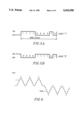
- FIG. 5A shows one example of a code pattern formulated according to the principles of the present invention to include two frequency components
- FIG. 5B shows another example of a code pattern formulated according to the principles of the present invention to include two frequency components
- FIG. 6 is a waveform chart showing a pattern signal passing through a correlating detector
- FIG. 7 is a block diagram showing a first embodiment of a transmitting circuit constructed according to the principles of the present invention.
- FIG. 8 is a block diagram showing a third embodiment of a receiving circuit constructed according to the principles of the present invention.
- FIG. 9 is a block diagram showing a fourth embodiment of a receiving circuit according constructed according to the principles of the present invention.
- FIG. 10 shows the general structure of a correlating detector
- FIG. 11 shows a code format arranged according to the principles of the present invention
- FIG. 12 is a flow chart illustrating a series of time corrective processes performed according to the principles of the present invention.
- FIG. 13 is a flow chart illustrating a series of reservation processes performed according to the principles of the present invention.
- FIG. 1 illustrates the configuration for inserting a code relating to a specific function such as time correction or reservation of a receiving side for a video signal to be sent from a transmitting side.
- a given code generated from a code generator 11 is inserted in the video signal in a code inserter 10 and then transmitted to a receiving circuit through a video transmitter 12.
- the video signal includes a vertical blanking interval (VBI). Strictly speaking, the code is to be inserted in the VBI prior to transmission.
- VBI vertical blanking interval
- FIG. 2 illustrates the configuration for decoding the code-inserted video signal at a receiving side and sending the code to a timer circuit or a reservation circuit.
- a video receiver 21 receives the video signal transmitted from the transmitting side.
- a code decoder 22 detects the code from the video signal and provides the code to the timer circuit or the reservation circuit of a TV or VTR.
- Adjusting a current time and reserving the recording of a program i.e. storing information to automatically control a television to come on a certain channel or a recorder to come on and/or record a program on a certain channel
- a TV or VTR controls the timer circuit by detecting and decoding a time code inserted in an empty area of a video signal channel transmitted from a broadcasting station. Therefore, the time is automatically adjusted.
- the TV or VTR is maintained in a stand-by state.
- a time correcting mode represents a mode set by the time correction instruction of the user using the remote control unit or other input unit.
- the broadcasting station of the transmitting side transmits the video signal in which the code having channel information and time information for reservation of recording a program is inserted during program notice broadcasting (i.e. a commercial or preview regarding a program to be transmitted at a later time). Then the TV or VTR of the receiving side turns on a display lamp by decoding the code. In this case, if the user who is watching the TV senses the display lamp which is turned on and then wants to reserve the recording of the program and presses a reservation key in the remote control unit or other input unit, the program reservation information decoded from the code is provided to the reservation circuit.
- the reservation key is a one-touch key which may be activated by touching the key one time.
- the reservation for recording of the program is automatically implemented. Since the user can reserve the recording of the program while watching the program notice being broadcast and the reservation of the recording of the program is simply performed by a one-time procedure implemented by the user having to touch activate the reservation key by a single touch, it is very convenient. A series of reservation process is shown in FIG. 13.
- FIG. 3 illustrates a first embodiment of the receiving circuit of FIG. 2.
- the receiving circuit includes a code detector 31, a low-pass filter 32 and an error corrector 33. If the code-inserted video signal which is the same as the input of the timer circuit or the reservation circuit of the TV or VTR are sent from the broadcasting station, the code detector 31 detects the code from the VBI in which the code is inserted and the low-pass filter 32 eliminates a noise component contained in the detected code.
- the error corrector 33 checks whether or not the code is normally received and sends the code to the timer circuit if the time correction key has been activated or the reservation circuit if the reservation key has been activated.
- FIG. 4 illustrates a second embodiment of the receiving circuit of FIG. 2.
- a code detector 41 a correlating detector 42, a comparator 43 and an error corrector 44.
- the correlating detector 42 is known in the art and disclosed in detail in Korea patent No. 90-13136 entitled Filtering Method In A Converting Domain Using Pipeline Structure attached and incorporated herein.
- the structure of the correlating detector 42 is shown in FIG. 10.
- the comparator 43 If the code detected from the code detector 41 passes through the correlating circuit 42, a waveform shown in FIG. 6 is generated.
- the comparator 43 generates "1" (or "0") when the waveform is greater than a first threshold value TH1 and generates "0" (or "1") when it is less than a second threshold value TH2. Otherwise the waveform is not considered as the code. Namely, if a correlated degree is greater than a first level or less than a second level, it is judged as a code, and if the correlated degree is between the two levels, it is judged as a video signal. Then the error corrector 44 executes a parity check in order to confirm that the code is accurately received. If it is confirmed that an accurate code is received, the display lamp is turned on so as to notify the user that the reservation of a program is possible.
- the recording time reservation can be automatically implemented by pressing a reservation key only once. That is, since the code is provided to the reservation circuit of the TV by the key input of the user, the TV is automatically turned on at the time corresponding to the time information of the code and the program is recorded on the tape in the VTR or other video recording machine.
- the patterned bit of the code is transmitted from the broadcasting station. In other words, the waveform of a shape such as the coefficient of the correlating detector 42 is considered as one bit.
- FIG. 7 illustrates a further embodiment of the transmitting circuit of FIG. 1.
- the transmitting circuit includes a band-elimination filter 71, a code generator 72, a modulator 73 and a frequency synthesizer 74.
- a vertical blanking interval does not have a position where the code can be inserted, then one of the code signals shown in FIGS. 5A and 5B is inserted in an empty frequency band of the video signal by frequency modulation. If there is no empty frequency band, the code signal is inserted into a specific frequency band, as explained below.
- a broadcasting station is set up as one of either a first type in which the time correction code and the program reservation code is inserted into the vertical blanking interval of the video signal, or a second type in which the time correction code and the program reservation code is inserted into a specific frequency band of predetermined line of the video signal.
- Code generator 72 generates a code signal having a format as shown in either FIG. 5A or FIG. 5B so as to enable a decoder in a receiving circuit to respond to a code inserted video signal transmitted by a broadcasting station of the second type. When there is an empty frequency band, band-elimination filtering is not performed. If there is no empty frequency band, a common terminal of a switch SW1 is connected to a terminal b in response to a line detecting signal.
- the line detecting signal is generated according to a method well known in the art and is indicative of a predetermined line of the video signal. Then the band-elimination filter 71 subtracts a specific frequency f from the input video signal and transmits the resultant signal to the frequency synthesizer 74.
- the modulator 74 modulates the code generated from the code generator 72, i.e. the code signal of either FIG. 5A or FIG. 5B and the time correction code or the program reservation code, to the specific frequency f and transmits the modulated signal to the frequency synthesizer 74.
- the frequency synthesizer 74 inserts the modulated code into the video signal of which the specific frequency band has been eliminated and thus generates the code-inserted video signal.
- FIG. 8 shows another embodiment of the receiving circuit of FIG. 2.
- the receiving circuit has a band-pass filter 81, a demodulator comprised of an absolute value circuit 82 and a lowpass filter 83, a correlating detector 84, a comparator 85 and an error corrector 86.
- switch SW2 provides the code inserted video signal to a band-pass filter 81 which in turn extracts the modulated signal.
- the absolute value circuit 82 calculates an absolute value of the extracted signal for signal restoration and the low-pass filter 83 eliminates a noise component.
- the correlating detector 84 forms a mutual correlating function between the noise-eliminated absolute value and a code format. Although the result of the correlating detection is judged as code data, the comparator 85 checks the waveform generated from the correlating detector 84 once again to confirm the code data. If the waveform is greater than the first threshold value TH1, the comparator 85 generates "1", and if the waveform is less than the second threshold value TH2, it generates "0". The error corrector 86 parity-checks the compared result to confirm whether or not the code is normally received. If the normal reception is confirmed, the error corrector 86 transmits the code to the timer circuit or the reservation circuit. The correlating detector 84, comparator 85 and error corrector 86 are added to improve reliability and these are optional devices.
- FIG. 9 shows yet another embodiment of the receiving circuit of FIG. 2.
- the receiving circuit has first and second decoders 91 and 92, and an accumulator 93.
- the first decoder 91 decodes the video signal to detect a teletext or caption signal.
- the second decoder 92 again decodes the result decoded from of the first decoder 91.
- the accumulator 93 counts how many times the same code is repeatedly received and accumulates the result decoded from the second decoder 92.
- the accumulator 92 is to improve reliability and this is also an optional device. Although not shown in FIG. 8, if the accumulator is connected to the receiving circuit of FIG. 8, since the code data is judged as effective data when it is received as much as a given number, the reliability is improved. If the receiving circuit has the accumulator, the transmitting circuit should include a corresponding unit.
- a mode is assigned to serially transmit the code-inserted video signal by the unit of field or frame.
- a code for the field or frame should be additionally inserted in an NTSC broadcasting system. That is, a multiplexing system of time base is used. For example,
- first field reservation, on/off, week, date, AM/PM, minute.
- the caption or teletext broadcasting is used.
- the caption or teletext broadcasting code is used as a code relating to the timecast or the reservation of time. If a specific character, character string or code is previously defined at the transmitting side and then the code is inserted, the receiving circuit decodes the code through the first decoder 91 so as to transmit the code to the timer circuit or the reservation circuit.
- the first decoder 91 it is desirable to add the accumulator in order to guarantee the accuracy of the signal.
- the code inserted in the video signal should satisfy the following conditions:
- FIGS. 5A and 5B show examples of the pattern including two frequency components.
- FIG. 11 shows one example of a code format, and various modifications are possible.
- FIG. 11 shows, for example, a control code, which may be as shown in FIGS. 5A and 5B for example or may be a well known teletext/caption control code.
- a channel identification which informs the reservation circuit which channel a program will be broadcast on.
- a date and time is provided for the start of the program and a date and time for the end of the program.
- These date and time codes may be used to turn on and turn off the receiving device, respectively.
- the inventive circuit and method can be applied to a dedicated channel for announcing a program, a high definition television (HDTV), and the like. If the TV broadcasting station or community cable broadcasting station provides such services, convenient functions can be expected. Further, it is possible to be applied between a TV or other machine.
- HDTV high definition television
Abstract
Description
Claims (20)
Applications Claiming Priority (4)
| Application Number | Priority Date | Filing Date | Title |
|---|---|---|---|
| KR920020398 | 1992-10-31 | ||
| KR20398/1992 | 1992-10-31 | ||
| KR21545/1993 | 1993-10-16 | ||
| KR1019930021545A KR960002504B1 (en) | 1992-10-31 | 1993-10-16 | Video signal transmitting & receiving circuit and the method thereof |
Publications (1)
| Publication Number | Publication Date |
|---|---|
| US5432558A true US5432558A (en) | 1995-07-11 |
Family
ID=26629335
Family Applications (1)
| Application Number | Title | Priority Date | Filing Date |
|---|---|---|---|
| US08/142,909 Expired - Lifetime US5432558A (en) | 1992-10-31 | 1993-10-29 | Circuit and method for transmitting/receiving a code-inserted video signal |
Country Status (2)
| Country | Link |
|---|---|
| US (1) | US5432558A (en) |
| KR (1) | KR960002504B1 (en) |
Cited By (27)
| Publication number | Priority date | Publication date | Assignee | Title |
|---|---|---|---|---|
| US5500741A (en) * | 1993-02-18 | 1996-03-19 | Goldstar Co., Ltd. | VCR having capability of displaying time signal received from broadcasting stations |
| US5579061A (en) * | 1993-05-13 | 1996-11-26 | U.S. Philips Corporation | Transmitter for transmitting tuning data in a television signal and receiver for receiving same |
| US5617146A (en) * | 1994-07-18 | 1997-04-01 | Thomson Consumer Electronics, Inc. | System for controlling updates of extended data services (EDS) data |
| US5640484A (en) * | 1993-10-20 | 1997-06-17 | E. Guide, Inc. | Switch for automatic selection of television signal sources for delivery of television guide data |
| US5661526A (en) * | 1993-08-25 | 1997-08-26 | Sony Corporation | Broadcast signal receiver and tape recorder and, method of detecting additional information channel |
| US5699370A (en) * | 1994-02-17 | 1997-12-16 | Hitachi, Ltd. | Information recording and reproduction apparatus to be controlled by temporal information |
| US5852471A (en) * | 1995-06-20 | 1998-12-22 | Sony Corporation | Television multiplex data extracting apparatus |
| US5887243A (en) | 1981-11-03 | 1999-03-23 | Personalized Media Communications, L.L.C. | Signal processing apparatus and methods |
| US5900912A (en) * | 1994-11-28 | 1999-05-04 | Sony Corporation | Broadcasting signal receiver |
| US6341195B1 (en) * | 1994-12-28 | 2002-01-22 | E-Guide, Inc. | Apparatus and methods for a television on-screen guide |
| US20020010918A1 (en) * | 1994-12-28 | 2002-01-24 | E-Guide, Inc. | Apparatus and methods for a television on-screen guide |
| US20020056108A1 (en) * | 2000-08-04 | 2002-05-09 | Herbert Gerharter | Recording arrangement having recording control means |
| US20020092032A1 (en) * | 2000-03-16 | 2002-07-11 | Yeong-Taeg Kim | Method and apparatus for broadcasting, viewing, reserving and/or delayed viewing of digital television programs |
| US20020092022A1 (en) * | 2000-11-16 | 2002-07-11 | Dudkicwicz Gil Gavriel | System and method for using programming event timing data in a recording device |
| US20020188945A1 (en) * | 2001-06-06 | 2002-12-12 | Mcgee Tom | Enhanced EPG to find program start and segments |
| US20030093783A1 (en) * | 2001-11-09 | 2003-05-15 | Daniel Nelson | Apparatus and method for detecting and correcting a corrupted broadcast time code |
| US6757025B1 (en) * | 1999-04-09 | 2004-06-29 | Sony Corporation | Method for switching input terminals based on incoming signal format |
| US6775842B1 (en) * | 1999-05-20 | 2004-08-10 | Koninklijke Philips Electronics N.V. | Method and arrangement for transmitting and receiving encoded images |
| US20060150223A1 (en) * | 2004-12-02 | 2006-07-06 | Funai Electric Co., Ltd. | Digital TV broadcast signal receiving system and outdoor appliance used therein |
| US20060171474A1 (en) * | 2002-10-23 | 2006-08-03 | Nielsen Media Research | Digital data insertion apparatus and methods for use with compressed audio/video data |
| US20070040934A1 (en) * | 2004-04-07 | 2007-02-22 | Arun Ramaswamy | Data insertion apparatus and methods for use with compressed audio/video data |
| US7742737B2 (en) | 2002-01-08 | 2010-06-22 | The Nielsen Company (Us), Llc. | Methods and apparatus for identifying a digital audio signal |
| US7769344B1 (en) | 1981-11-03 | 2010-08-03 | Personalized Media Communications, Llc | Signal processing apparatus and methods |
| US20110176683A1 (en) * | 1999-11-19 | 2011-07-21 | Nippon Telegraph And Telephone Corporation | Information Communication Apparatus, Transmission Apparatus And Receiving Apparatus |
| US20120300972A1 (en) * | 2011-05-26 | 2012-11-29 | Rodriguez Tony F | Image-related methods and systems |
| US9525798B2 (en) | 2011-05-26 | 2016-12-20 | Digimarc Corporation | Image-related methods and systems |
| USRE47642E1 (en) | 1981-11-03 | 2019-10-08 | Personalized Media Communications LLC | Signal processing apparatus and methods |
Citations (11)
| Publication number | Priority date | Publication date | Assignee | Title |
|---|---|---|---|---|
| US4691351A (en) * | 1984-11-29 | 1987-09-01 | Sony Corporation | Television signal receiving apparatus |
| US4706121A (en) * | 1985-07-12 | 1987-11-10 | Patrick Young | TV schedule system and process |
| US4805020A (en) * | 1983-03-21 | 1989-02-14 | Greenberg Burton L | Television program transmission verification method and apparatus |
| US4908707A (en) * | 1987-07-20 | 1990-03-13 | U.S. Philips Corp. | Video cassette recorder programming via teletext transmissions |
| US4977455A (en) * | 1988-07-15 | 1990-12-11 | Insight Telecast, Inc. | System and process for VCR scheduling |
| US5016273A (en) * | 1989-01-09 | 1991-05-14 | At&E Corporation | Dual communication mode video tape recorder |
| US5063456A (en) * | 1988-08-12 | 1991-11-05 | Hitachi, Ltd. | Video signal processor |
| US5179439A (en) * | 1988-02-05 | 1993-01-12 | Hashimoto Corporation | Personal channel display device in a tv program reservation system |
| US5195134A (en) * | 1990-03-27 | 1993-03-16 | Sony Corporation | Transmitting, receiving, and automatic recording system for programs with time and channel information |
| US5210611A (en) * | 1991-08-12 | 1993-05-11 | Keen Y. Yee | Automatic tuning radio/TV using filtered seek |
| US5260788A (en) * | 1990-11-29 | 1993-11-09 | Matsushita Electric Industrial Co., Ltd. | Text broadcast receiver |
-
1993
- 1993-10-16 KR KR1019930021545A patent/KR960002504B1/en not_active IP Right Cessation
- 1993-10-29 US US08/142,909 patent/US5432558A/en not_active Expired - Lifetime
Patent Citations (13)
| Publication number | Priority date | Publication date | Assignee | Title |
|---|---|---|---|---|
| US4805020A (en) * | 1983-03-21 | 1989-02-14 | Greenberg Burton L | Television program transmission verification method and apparatus |
| US4691351A (en) * | 1984-11-29 | 1987-09-01 | Sony Corporation | Television signal receiving apparatus |
| US4706121A (en) * | 1985-07-12 | 1987-11-10 | Patrick Young | TV schedule system and process |
| US4706121B1 (en) * | 1985-07-12 | 1993-12-14 | Insight Telecast, Inc. | Tv schedule system and process |
| US4908707A (en) * | 1987-07-20 | 1990-03-13 | U.S. Philips Corp. | Video cassette recorder programming via teletext transmissions |
| US5179439A (en) * | 1988-02-05 | 1993-01-12 | Hashimoto Corporation | Personal channel display device in a tv program reservation system |
| US4977455B1 (en) * | 1988-07-15 | 1993-04-13 | System and process for vcr scheduling | |
| US4977455A (en) * | 1988-07-15 | 1990-12-11 | Insight Telecast, Inc. | System and process for VCR scheduling |
| US5063456A (en) * | 1988-08-12 | 1991-11-05 | Hitachi, Ltd. | Video signal processor |
| US5016273A (en) * | 1989-01-09 | 1991-05-14 | At&E Corporation | Dual communication mode video tape recorder |
| US5195134A (en) * | 1990-03-27 | 1993-03-16 | Sony Corporation | Transmitting, receiving, and automatic recording system for programs with time and channel information |
| US5260788A (en) * | 1990-11-29 | 1993-11-09 | Matsushita Electric Industrial Co., Ltd. | Text broadcast receiver |
| US5210611A (en) * | 1991-08-12 | 1993-05-11 | Keen Y. Yee | Automatic tuning radio/TV using filtered seek |
Cited By (138)
| Publication number | Priority date | Publication date | Assignee | Title |
|---|---|---|---|---|
| US9043859B1 (en) | 1981-11-02 | 2015-05-26 | Personalized Media Communications, Llc | Signal processing apparatus and methods |
| US7864248B1 (en) | 1981-11-03 | 2011-01-04 | Personalized Media Communications, Llc | Signal processing apparatus and methods |
| US8711885B1 (en) | 1981-11-03 | 2014-04-29 | Personalized Media Communications LLC | Signal processing apparatus and methods |
| USRE48682E1 (en) | 1981-11-03 | 2021-08-10 | Personalized Media Communications LLC | Providing subscriber specific content in a network |
| USRE48633E1 (en) | 1981-11-03 | 2021-07-06 | Personalized Media Communications LLC | Reprogramming of a programmable device of a specific version |
| USRE48565E1 (en) | 1981-11-03 | 2021-05-18 | Personalized Media Communications LLC | Providing a subscriber specific solution in a computer network |
| USRE48484E1 (en) | 1981-11-03 | 2021-03-23 | Personalized Media Communications, Llc | Signal processing apparatus and methods |
| US10715835B1 (en) | 1981-11-03 | 2020-07-14 | John Christopher Harvey | Signal processing apparatus and methods |
| US7870581B1 (en) | 1981-11-03 | 2011-01-11 | Personalized Media Communications, Llc | Signal processing apparatus and methods |
| US10609425B1 (en) | 1981-11-03 | 2020-03-31 | Personalized Media Communications, L.L.C. | Signal processing apparatus and methods |
| US7889865B1 (en) | 1981-11-03 | 2011-02-15 | Personalized Media Communications, L.L.C. | Signal processing apparatus and methods |
| USRE47867E1 (en) | 1981-11-03 | 2020-02-18 | Personalized Media Communications LLC | Signal processing apparatus and methods |
| US10523350B1 (en) | 1981-11-03 | 2019-12-31 | Personalized Media Communications LLC | Signal processing apparatus and methods |
| USRE47642E1 (en) | 1981-11-03 | 2019-10-08 | Personalized Media Communications LLC | Signal processing apparatus and methods |
| US10334292B1 (en) | 1981-11-03 | 2019-06-25 | Personalized Media Communications LLC | Signal processing apparatus and methods |
| US9674560B1 (en) | 1981-11-03 | 2017-06-06 | Personalized Media Communications LLC | Signal processing apparatus and methods |
| US9294205B1 (en) | 1981-11-03 | 2016-03-22 | Personalized Media Communications LLC | Signal processing apparatus and methods |
| US9210370B1 (en) | 1981-11-03 | 2015-12-08 | Personalized Media Communications LLC | Signal processing apparatus and methods |
| US9038124B1 (en) | 1981-11-03 | 2015-05-19 | Personalized Media Communications, Llc | Signal processing apparatus and methods |
| US8973034B1 (en) | 1981-11-03 | 2015-03-03 | Personalized Media Communications LLC | Signal processing apparatus and methods |
| US8914825B1 (en) | 1981-11-03 | 2014-12-16 | Personalized Media Communications LLC | Signal processing apparatus and methods |
| US8893177B1 (en) | 1981-11-03 | 2014-11-18 | {Personalized Media Communications, LLC | Signal processing apparatus and methods |
| US8869229B1 (en) | 1981-11-03 | 2014-10-21 | Personalized Media Communications, Llc | Signal processing apparatus and methods |
| US8869228B1 (en) | 1981-11-03 | 2014-10-21 | Personalized Media Communications, Llc | Signal processing apparatus and methods |
| US8839293B1 (en) | 1981-11-03 | 2014-09-16 | Personalized Media Communications, Llc | Signal processing apparatus and methods |
| US8804727B1 (en) | 1981-11-03 | 2014-08-12 | Personalized Media Communications, Llc | Signal processing apparatus and methods |
| US8752088B1 (en) | 1981-11-03 | 2014-06-10 | Personalized Media Communications LLC | Signal processing apparatus and methods |
| US8739241B1 (en) | 1981-11-03 | 2014-05-27 | Personalized Media Communications LLC | Signal processing apparatus and methods |
| US7734251B1 (en) | 1981-11-03 | 2010-06-08 | Personalized Media Communications, Llc | Signal processing apparatus and methods |
| US8713624B1 (en) | 1981-11-03 | 2014-04-29 | Personalized Media Communications LLC | Signal processing apparatus and methods |
| US7747217B1 (en) | 1981-11-03 | 2010-06-29 | Personalized Media Communications, Llc | Signal processing apparatus and methods |
| US7752649B1 (en) | 1981-11-03 | 2010-07-06 | Personalized Media Communications, Llc | Signal processing apparatus and methods |
| US7752650B1 (en) | 1981-11-03 | 2010-07-06 | Personalized Media Communications, Llc | Signal processing apparatus and methods |
| US7761890B1 (en) | 1981-11-03 | 2010-07-20 | Personalized Media Communications, Llc | Signal processing apparatus and methods |
| US7764685B1 (en) | 1981-11-03 | 2010-07-27 | Personalized Media Communications, L.L.C. | Signal processing apparatus and methods |
| US7769170B1 (en) | 1981-11-03 | 2010-08-03 | Personalized Media Communications, Llc | Signal processing apparatus and methods |
| US7769344B1 (en) | 1981-11-03 | 2010-08-03 | Personalized Media Communications, Llc | Signal processing apparatus and methods |
| US7783252B1 (en) | 1981-11-03 | 2010-08-24 | Personalized Media Communications, Llc | Signal processing apparatus and methods |
| US7784082B1 (en) | 1981-11-03 | 2010-08-24 | Personalized Media Communications, Llc | Signal processing apparatus and methods |
| US7793332B1 (en) | 1981-11-03 | 2010-09-07 | Personalized Media Communications, Llc | Signal processing apparatus and methods |
| US7797717B1 (en) | 1981-11-03 | 2010-09-14 | Personalized Media Communications, Llc | Signal processing apparatus and methods |
| US7801304B1 (en) | 1981-11-03 | 2010-09-21 | Personalized Media Communications, Llc | Signal processing apparatus and methods |
| US7805738B1 (en) | 1981-11-03 | 2010-09-28 | Personalized Media Communications, Llc | Signal processing apparatus and methods |
| US7805748B1 (en) | 1981-11-03 | 2010-09-28 | Personalized Media Communications, Llc | Signal processing apparatus and methods |
| US7810115B1 (en) | 1981-11-03 | 2010-10-05 | Personalized Media Communications, Llc | Signal processing apparatus and methods |
| US7814526B1 (en) | 1981-11-03 | 2010-10-12 | Personalized Media Communications, Llc | Signal processing apparatus and methods |
| US7818777B1 (en) | 1981-11-03 | 2010-10-19 | Personalized Media Communications, Llc | Signal processing apparatus and methods |
| US7818776B1 (en) | 1981-11-03 | 2010-10-19 | Personalized Media Communications, Llc | Signal processing apparatus and methods |
| US7818778B1 (en) | 1981-11-03 | 2010-10-19 | Personalized Media Communications, Llc | Signal processing apparatus and methods |
| US7817208B1 (en) | 1981-11-03 | 2010-10-19 | Personalized Media Communications, Llc | Signal processing apparatus and methods |
| US7823175B1 (en) | 1981-11-03 | 2010-10-26 | Personalized Media Communications LLC | Signal processing apparatus and methods |
| US7827587B1 (en) | 1981-11-03 | 2010-11-02 | Personalized Media Communications, Llc | Signal processing apparatus and methods |
| US7827586B1 (en) | 1981-11-03 | 2010-11-02 | Personalized Media Communications, Llc | Signal processing apparatus and methods |
| US7831204B1 (en) | 1981-11-03 | 2010-11-09 | Personalized Media Communications, Llc | Signal processing apparatus and methods |
| US7836480B1 (en) | 1981-11-03 | 2010-11-16 | Personalized Media Communications, Llc | Signal processing apparatus and methods |
| US7840976B1 (en) | 1981-11-03 | 2010-11-23 | Personalized Media Communications, Llc | Signal processing apparatus and methods |
| US7844995B1 (en) | 1981-11-03 | 2010-11-30 | Personalized Media Communications, Llc | Signal processing apparatus and methods |
| US7849493B1 (en) | 1981-11-03 | 2010-12-07 | Personalized Media Communications, Llc | Signal processing apparatus and methods |
| US7849480B1 (en) | 1981-11-03 | 2010-12-07 | Personalized Media Communications LLC | Signal processing apparatus and methods |
| US7849479B1 (en) | 1981-11-03 | 2010-12-07 | Personalized Media Communications, Llc | Signal processing apparatus and methods |
| US8683539B1 (en) | 1981-11-03 | 2014-03-25 | Personalized Media Communications, Llc | Signal processing apparatus and methods |
| US7856649B1 (en) | 1981-11-03 | 2010-12-21 | Personalized Media Communications, Llc | Signal processing apparatus and methods |
| US7860249B1 (en) | 1981-11-03 | 2010-12-28 | Personalized Media Communications LLC | Signal processing apparatus and methods |
| US7861278B1 (en) | 1981-11-03 | 2010-12-28 | Personalized Media Communications, Llc | Signal processing apparatus and methods |
| US7860131B1 (en) | 1981-11-03 | 2010-12-28 | Personalized Media Communications, Llc | Signal processing apparatus and methods |
| US7861263B1 (en) | 1981-11-03 | 2010-12-28 | Personalized Media Communications, Llc | Signal processing apparatus and methods |
| US7864956B1 (en) | 1981-11-03 | 2011-01-04 | Personalized Media Communications, Llc | Signal processing apparatus and methods |
| US7865920B1 (en) | 1981-11-03 | 2011-01-04 | Personalized Media Communications LLC | Signal processing apparatus and methods |
| US5887243A (en) | 1981-11-03 | 1999-03-23 | Personalized Media Communications, L.L.C. | Signal processing apparatus and methods |
| US10616638B1 (en) | 1981-11-03 | 2020-04-07 | Personalized Media Communications LLC | Signal processing apparatus and methods |
| US8675775B1 (en) | 1981-11-03 | 2014-03-18 | Personalized Media Communications, Llc | Signal processing apparatus and methods |
| US8646001B1 (en) | 1981-11-03 | 2014-02-04 | Personalized Media Communications, Llc | Signal processing apparatus and methods |
| US7908638B1 (en) | 1981-11-03 | 2011-03-15 | Personalized Media Communications LLC | Signal processing apparatus and methods |
| US7926084B1 (en) | 1981-11-03 | 2011-04-12 | Personalized Media Communications LLC | Signal processing apparatus and methods |
| US7940931B1 (en) | 1981-11-03 | 2011-05-10 | Personalized Media Communications LLC | Signal processing apparatus and methods |
| US7953223B1 (en) | 1981-11-03 | 2011-05-31 | Personalized Media Communications, L.L.C. | Signal processing apparatus and methods |
| US8640184B1 (en) | 1981-11-03 | 2014-01-28 | Personalized Media Communications, Llc | Signal processing apparatus and methods |
| US8635644B1 (en) | 1981-11-03 | 2014-01-21 | Personalized Media Communications LLC | Signal processing apparatus and methods |
| US8621547B1 (en) | 1981-11-03 | 2013-12-31 | Personalized Media Communications, Llc | Signal processing apparatus and methods |
| US7992169B1 (en) | 1981-11-03 | 2011-08-02 | Personalized Media Communications LLC | Signal processing apparatus and methods |
| US8046791B1 (en) | 1981-11-03 | 2011-10-25 | Personalized Media Communications, Llc | Signal processing apparatus and methods |
| US8060903B1 (en) | 1981-11-03 | 2011-11-15 | Personalized Media PMC Communications, L.L.C. | Signal processing apparatus and methods |
| US8112782B1 (en) | 1981-11-03 | 2012-02-07 | Personalized Media Communications, Llc | Signal processing apparatus and methods |
| US8191091B1 (en) | 1981-11-03 | 2012-05-29 | Personalized Media Communications, Llc | Signal processing apparatus and methods |
| US8613034B1 (en) | 1981-11-03 | 2013-12-17 | Personalized Media Communications, Llc | Signal processing apparatus and methods |
| US8607296B1 (en) | 1981-11-03 | 2013-12-10 | Personalized Media Communications LLC | Signal processing apparatus and methods |
| US8555310B1 (en) | 1981-11-03 | 2013-10-08 | Personalized Media Communications, Llc | Signal processing apparatus and methods |
| US8559635B1 (en) | 1981-11-03 | 2013-10-15 | Personalized Media Communications, L.L.C. | Signal processing apparatus and methods |
| US8558950B1 (en) | 1981-11-03 | 2013-10-15 | Personalized Media Communications LLC | Signal processing apparatus and methods |
| US8566868B1 (en) | 1981-11-03 | 2013-10-22 | Personalized Media Communications, L.L.C. | Signal processing apparatus and methods |
| US8572671B1 (en) | 1981-11-03 | 2013-10-29 | Personalized Media Communications LLC | Signal processing apparatus and methods |
| US8584162B1 (en) | 1981-11-03 | 2013-11-12 | Personalized Media Communications LLC | Signal processing apparatus and methods |
| US8587720B1 (en) | 1981-11-03 | 2013-11-19 | Personalized Media Communications LLC | Signal processing apparatus and methods |
| US8601528B1 (en) | 1981-11-03 | 2013-12-03 | Personalized Media Communications, L.L.C. | Signal processing apparatus and methods |
| US7966640B1 (en) | 1987-09-11 | 2011-06-21 | Personalized Media Communications, Llc | Signal processing apparatus and methods |
| US7958527B1 (en) | 1987-09-11 | 2011-06-07 | Personalized Media Communications, Llc | Signal processing apparatus and methods |
| US5500741A (en) * | 1993-02-18 | 1996-03-19 | Goldstar Co., Ltd. | VCR having capability of displaying time signal received from broadcasting stations |
| US5668915A (en) * | 1993-02-18 | 1997-09-16 | Goldstar Co., Ltd. | Method for automatically setting VCR clock based on a broadcast time signal and displaying time |
| US5579061A (en) * | 1993-05-13 | 1996-11-26 | U.S. Philips Corporation | Transmitter for transmitting tuning data in a television signal and receiver for receiving same |
| US6025887A (en) * | 1993-05-13 | 2000-02-15 | U.S. Philips Corporation | Transmitter for transmitting tuning data in a television signal and receiver for receiving same |
| US5661526A (en) * | 1993-08-25 | 1997-08-26 | Sony Corporation | Broadcast signal receiver and tape recorder and, method of detecting additional information channel |
| US5640484A (en) * | 1993-10-20 | 1997-06-17 | E. Guide, Inc. | Switch for automatic selection of television signal sources for delivery of television guide data |
| US5930274A (en) * | 1994-02-17 | 1999-07-27 | Hitachi, Ltd. | Information recording and reproduction apparatus to be controlled by temporal information |
| US5699370A (en) * | 1994-02-17 | 1997-12-16 | Hitachi, Ltd. | Information recording and reproduction apparatus to be controlled by temporal information |
| US5617146A (en) * | 1994-07-18 | 1997-04-01 | Thomson Consumer Electronics, Inc. | System for controlling updates of extended data services (EDS) data |
| US5900912A (en) * | 1994-11-28 | 1999-05-04 | Sony Corporation | Broadcasting signal receiver |
| US6341195B1 (en) * | 1994-12-28 | 2002-01-22 | E-Guide, Inc. | Apparatus and methods for a television on-screen guide |
| US20020010918A1 (en) * | 1994-12-28 | 2002-01-24 | E-Guide, Inc. | Apparatus and methods for a television on-screen guide |
| US5852471A (en) * | 1995-06-20 | 1998-12-22 | Sony Corporation | Television multiplex data extracting apparatus |
| US6757025B1 (en) * | 1999-04-09 | 2004-06-29 | Sony Corporation | Method for switching input terminals based on incoming signal format |
| US6775842B1 (en) * | 1999-05-20 | 2004-08-10 | Koninklijke Philips Electronics N.V. | Method and arrangement for transmitting and receiving encoded images |
| US8635072B2 (en) * | 1999-11-19 | 2014-01-21 | Nippon Telegraph And Telephone Corporation | Information communication using majority logic for machine control signals extracted from audible sound signals |
| US20110176683A1 (en) * | 1999-11-19 | 2011-07-21 | Nippon Telegraph And Telephone Corporation | Information Communication Apparatus, Transmission Apparatus And Receiving Apparatus |
| US7340762B2 (en) * | 2000-03-16 | 2008-03-04 | Samsung Electronics Co., Ltd. | Method and apparatus for broadcasting, viewing, reserving and/or delayed viewing of digital television programs |
| US20020092032A1 (en) * | 2000-03-16 | 2002-07-11 | Yeong-Taeg Kim | Method and apparatus for broadcasting, viewing, reserving and/or delayed viewing of digital television programs |
| US20020056108A1 (en) * | 2000-08-04 | 2002-05-09 | Herbert Gerharter | Recording arrangement having recording control means |
| US7242845B2 (en) * | 2000-08-04 | 2007-07-10 | Koninklijke Philips Electronics N.V. | Recording arrangement having recording control means |
| US20020092022A1 (en) * | 2000-11-16 | 2002-07-11 | Dudkicwicz Gil Gavriel | System and method for using programming event timing data in a recording device |
| US20020188945A1 (en) * | 2001-06-06 | 2002-12-12 | Mcgee Tom | Enhanced EPG to find program start and segments |
| WO2003043331A1 (en) * | 2001-11-09 | 2003-05-22 | Nielsen Media Research, Inc. | Apparatus and method for detecting and correcting a corrupted broadcast time code |
| US20030093783A1 (en) * | 2001-11-09 | 2003-05-15 | Daniel Nelson | Apparatus and method for detecting and correcting a corrupted broadcast time code |
| US7117513B2 (en) | 2001-11-09 | 2006-10-03 | Nielsen Media Research, Inc. | Apparatus and method for detecting and correcting a corrupted broadcast time code |
| US8548373B2 (en) | 2002-01-08 | 2013-10-01 | The Nielsen Company (Us), Llc | Methods and apparatus for identifying a digital audio signal |
| US7742737B2 (en) | 2002-01-08 | 2010-06-22 | The Nielsen Company (Us), Llc. | Methods and apparatus for identifying a digital audio signal |
| US10681399B2 (en) | 2002-10-23 | 2020-06-09 | The Nielsen Company (Us), Llc | Digital data insertion apparatus and methods for use with compressed audio/video data |
| US9106347B2 (en) | 2002-10-23 | 2015-08-11 | The Nielsen Company (Us), Llc | Digital data insertion apparatus and methods for use with compressed audio/video data |
| US9900633B2 (en) | 2002-10-23 | 2018-02-20 | The Nielsen Company (Us), Llc | Digital data insertion apparatus and methods for use with compressed audio/video data |
| US11223858B2 (en) | 2002-10-23 | 2022-01-11 | The Nielsen Company (Us), Llc | Digital data insertion apparatus and methods for use with compressed audio/video data |
| US20060171474A1 (en) * | 2002-10-23 | 2006-08-03 | Nielsen Media Research | Digital data insertion apparatus and methods for use with compressed audio/video data |
| US8600216B2 (en) | 2004-04-07 | 2013-12-03 | The Nielsen Company (Us), Llc | Data insertion apparatus and methods for use with compressed audio/video data |
| US20070040934A1 (en) * | 2004-04-07 | 2007-02-22 | Arun Ramaswamy | Data insertion apparatus and methods for use with compressed audio/video data |
| US9332307B2 (en) | 2004-04-07 | 2016-05-03 | The Nielsen Company (Us), Llc | Data insertion apparatus and methods for use with compressed audio/video data |
| US7853124B2 (en) | 2004-04-07 | 2010-12-14 | The Nielsen Company (Us), Llc | Data insertion apparatus and methods for use with compressed audio/video data |
| US20110055860A1 (en) * | 2004-04-07 | 2011-03-03 | Arun Ramaswamy | Data insertion apparatus and methods for use with compressed audio/video data |
| US20060150223A1 (en) * | 2004-12-02 | 2006-07-06 | Funai Electric Co., Ltd. | Digital TV broadcast signal receiving system and outdoor appliance used therein |
| US9525798B2 (en) | 2011-05-26 | 2016-12-20 | Digimarc Corporation | Image-related methods and systems |
| US20120300972A1 (en) * | 2011-05-26 | 2012-11-29 | Rodriguez Tony F | Image-related methods and systems |
| US8699747B2 (en) * | 2011-05-26 | 2014-04-15 | Digimarc Corporation | Image-related methods and systems |
Also Published As
| Publication number | Publication date |
|---|---|
| KR960002504B1 (en) | 1996-02-17 |
| KR940010721A (en) | 1994-05-26 |
Similar Documents
| Publication | Publication Date | Title |
|---|---|---|
| US5432558A (en) | Circuit and method for transmitting/receiving a code-inserted video signal | |
| US5296931A (en) | Channel selecting method for programs of the same category | |
| US4641205A (en) | Television system scheduler with on-screen menu type programming prompting apparatus | |
| US5559550A (en) | Apparatus and methods for synchronizing a clock to a network clock | |
| EP0161512B1 (en) | Program identification system | |
| EP0681774B1 (en) | Display of closed captioning status | |
| EP0640897B1 (en) | Broadcast signal receivers | |
| CN1138411C (en) | Automatic screen words editing device and method for video-recorder recording | |
| KR100377843B1 (en) | Method and apparatus for correctly setting the time clock of a video receiver | |
| CN1240553A (en) | Television apparatus control system | |
| KR100231942B1 (en) | Local time difference automatic correcting method | |
| US6215951B1 (en) | Automatic title or description captioning for a VCR recording | |
| JPH08214224A (en) | Television device | |
| CN1040495C (en) | Automatic detection of kind of cable converter unit coupled to a VCR | |
| US7509024B2 (en) | Broadcast receiving apparatus, broadcast receiving system, and method of selecting manipulate signals in broadcast receiving system | |
| US5900912A (en) | Broadcasting signal receiver | |
| JP3387166B2 (en) | Broadcast signal receiver | |
| JP3318794B2 (en) | Broadcast signal receiver and information channel detection method thereof | |
| KR100215633B1 (en) | Method for modifying time-lag automatically using revervation system of vcr used in europe when travelling among nations | |
| US8280228B2 (en) | Information recording and reproducing apparatus | |
| KR960007950B1 (en) | Reservation recording setting method by program discrimination signal | |
| KR960013741B1 (en) | Reservation seeing and hearing and recording method of particular typed program | |
| KR960007203B1 (en) | Time display device | |
| KR960005128B1 (en) | Reservation recording method using teletext | |
| JP3469774B2 (en) | Receiver |
Legal Events
| Date | Code | Title | Description |
|---|---|---|---|
| AS | Assignment |
Owner name: SAMSUNG ELECTRONICS CO., LTD., KOREA, REPUBLIC OF Free format text: ASSIGNMENT OF ASSIGNORS INTEREST;ASSIGNOR:KIM, DEOK-HWAN;REEL/FRAME:006843/0583 Effective date: 19931206 |
|
| STCF | Information on status: patent grant |
Free format text: PATENTED CASE |
|
| FEPP | Fee payment procedure |
Free format text: PAYOR NUMBER ASSIGNED (ORIGINAL EVENT CODE: ASPN); ENTITY STATUS OF PATENT OWNER: LARGE ENTITY |
|
| FEPP | Fee payment procedure |
Free format text: PAYER NUMBER DE-ASSIGNED (ORIGINAL EVENT CODE: RMPN); ENTITY STATUS OF PATENT OWNER: LARGE ENTITY Free format text: PAYOR NUMBER ASSIGNED (ORIGINAL EVENT CODE: ASPN); ENTITY STATUS OF PATENT OWNER: LARGE ENTITY |
|
| FPAY | Fee payment |
Year of fee payment: 4 |
|
| REMI | Maintenance fee reminder mailed | ||
| FPAY | Fee payment |
Year of fee payment: 8 |
|
| FPAY | Fee payment |
Year of fee payment: 12 |