US5435451A - Bottle for containing a fluid - Google Patents
Bottle for containing a fluid Download PDFInfo
- Publication number
- US5435451A US5435451A US08/049,844 US4984493A US5435451A US 5435451 A US5435451 A US 5435451A US 4984493 A US4984493 A US 4984493A US 5435451 A US5435451 A US 5435451A
- Authority
- US
- United States
- Prior art keywords
- bottle
- fluid
- orifice
- sides
- gripping surfaces
- Prior art date
- Legal status (The legal status is an assumption and is not a legal conclusion. Google has not performed a legal analysis and makes no representation as to the accuracy of the status listed.)
- Expired - Lifetime
Links
Images

Classifications
-
- B—PERFORMING OPERATIONS; TRANSPORTING
- B65—CONVEYING; PACKING; STORING; HANDLING THIN OR FILAMENTARY MATERIAL
- B65D—CONTAINERS FOR STORAGE OR TRANSPORT OF ARTICLES OR MATERIALS, e.g. BAGS, BARRELS, BOTTLES, BOXES, CANS, CARTONS, CRATES, DRUMS, JARS, TANKS, HOPPERS, FORWARDING CONTAINERS; ACCESSORIES, CLOSURES, OR FITTINGS THEREFOR; PACKAGING ELEMENTS; PACKAGES
- B65D23/00—Details of bottles or jars not otherwise provided for
- B65D23/10—Handles
- B65D23/102—Gripping means formed in the walls, e.g. roughening, cavities, projections
-
- B—PERFORMING OPERATIONS; TRANSPORTING
- B65—CONVEYING; PACKING; STORING; HANDLING THIN OR FILAMENTARY MATERIAL
- B65D—CONTAINERS FOR STORAGE OR TRANSPORT OF ARTICLES OR MATERIALS, e.g. BAGS, BARRELS, BOTTLES, BOXES, CANS, CARTONS, CRATES, DRUMS, JARS, TANKS, HOPPERS, FORWARDING CONTAINERS; ACCESSORIES, CLOSURES, OR FITTINGS THEREFOR; PACKAGING ELEMENTS; PACKAGES
- B65D23/00—Details of bottles or jars not otherwise provided for
- B65D23/10—Handles
-
- B—PERFORMING OPERATIONS; TRANSPORTING
- B65—CONVEYING; PACKING; STORING; HANDLING THIN OR FILAMENTARY MATERIAL
- B65D—CONTAINERS FOR STORAGE OR TRANSPORT OF ARTICLES OR MATERIALS, e.g. BAGS, BARRELS, BOTTLES, BOXES, CANS, CARTONS, CRATES, DRUMS, JARS, TANKS, HOPPERS, FORWARDING CONTAINERS; ACCESSORIES, CLOSURES, OR FITTINGS THEREFOR; PACKAGING ELEMENTS; PACKAGES
- B65D1/00—Containers having bodies formed in one piece, e.g. by casting metallic material, by moulding plastics, by blowing vitreous material, by throwing ceramic material, by moulding pulped fibrous material, by deep-drawing operations performed on sheet material
- B65D1/02—Bottles or similar containers with necks or like restricted apertures, designed for pouring contents
- B65D1/0223—Bottles or similar containers with necks or like restricted apertures, designed for pouring contents characterised by shape
-
- B—PERFORMING OPERATIONS; TRANSPORTING
- B65—CONVEYING; PACKING; STORING; HANDLING THIN OR FILAMENTARY MATERIAL
- B65D—CONTAINERS FOR STORAGE OR TRANSPORT OF ARTICLES OR MATERIALS, e.g. BAGS, BARRELS, BOTTLES, BOXES, CANS, CARTONS, CRATES, DRUMS, JARS, TANKS, HOPPERS, FORWARDING CONTAINERS; ACCESSORIES, CLOSURES, OR FITTINGS THEREFOR; PACKAGING ELEMENTS; PACKAGES
- B65D2501/00—Containers having bodies formed in one piece
- B65D2501/0009—Bottles or similar containers with necks or like restricted apertures designed for pouring contents
- B65D2501/0018—Ribs
-
- B—PERFORMING OPERATIONS; TRANSPORTING
- B65—CONVEYING; PACKING; STORING; HANDLING THIN OR FILAMENTARY MATERIAL
- B65D—CONTAINERS FOR STORAGE OR TRANSPORT OF ARTICLES OR MATERIALS, e.g. BAGS, BARRELS, BOTTLES, BOXES, CANS, CARTONS, CRATES, DRUMS, JARS, TANKS, HOPPERS, FORWARDING CONTAINERS; ACCESSORIES, CLOSURES, OR FITTINGS THEREFOR; PACKAGING ELEMENTS; PACKAGES
- B65D2501/00—Containers having bodies formed in one piece
- B65D2501/0009—Bottles or similar containers with necks or like restricted apertures designed for pouring contents
- B65D2501/0081—Bottles of non-circular cross-section
Definitions
- This invention relates generally to bottle for containing a fluid, and more particularly, to bottles for containing and dispensing the fluids in conjunction with a dispensing system.
- Dispensing systems in the past have utilized bottles containing quantities of a fluid to be dispensed.
- the bottles are stored in an upright position, then inverted for dispensing of the fluid from the bottle through the dispensing system.
- a bottle according to this design patent is available from Soda-Mate Enterprises of Trumbull, Conn. for use with its Model S100 gravity feed fluid dispenser system and has a capacity of 0.667 milliliters.
- Such bottles are injection/blow molded from a suitable polymeric material, such as high density polyethylene and typically have a wall thickness of 0.018 inches. Bottles of this type, although functional, are somewhat limiting during use since their limited capacity requires replacement or refilling at relatively frequent intervals.
- Bottles having larger capacities may be employed. However, in conventional bottles having a larger capacity, the ratio of the wall thickness to the volume is reduced to the point where "paneling" occurs when the bottle is inverted and the fluid contained therein is being dispensed.
- the term "paneling" refers to inward and outward deflection in the walls of a bottle in a manner that induces fluctuations in the rate at which fluids are dispensed from a bottle.
- Paneling typically occurs with a bottle inverted and as the fluid is being dispensed. As the fluid level in the inverted bottle is reduced, a partial vacuum is gradually created in the "headspace" above the level of the fluid within the bottle. The walls of the bottle are gradually deflected inwardly under the influence of the partial vacuum. This deflection acts to enable the flow of the fluid from the bottle. The deflection increases until a point is reached where a quantity of the fluid has been dispensed from the bottle and the walls quickly flex outwardly, whereby the pressure in the head space is equalized with the ambient pressure.
- paneling prevents accurate metering of the dispensing of the fluid from the bottle. Furthermore, paneling may be exacerbated if the bottle is manually engaged and squeezed. Paneling is particularly a problem if the bottle is to be used in conjunction with a dispensing system for dispensing the fluid from the bottle in a controlled manner, and also to dilute the fluid with one or more other fluids.
- the wall thickness of the larger capacity bottle may be increased to resist paneling. However, this may not be completely successful, and increases the weight and expense of the bottle.
- a bottle for containing a fluid including a body having a cavity for receipt of a quantity of a fluid and an orifice communicating between the cavity and exteriorly of the bottle body. Means are provided to resist paneling when the bottle is in the inverted position and the fluid is being dispensed through the orifice.
- the bottle also includes a pair of spaced gripping surfaces adapted for manual engagement for manipulating the bottle between an upright position with the orifice directed upwardly, and an inverted position with the orifice directed downwardly.
- the means for resisting paneling includes a shoulder formed in the bottle body between each of the gripping surfaces and the orifice, wherein the shoulders stiffen the bottle body to resist paneling when the bottle body is inverted and the fluid is being dispensed.
- the bottle may additionally include a plurality of ribs projecting from each of the gripping surfaces, to facilitate manual grasping and manipulation of the bottle.
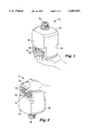
- FIG. 1 is an isometric view of a bottle according to the present invention in an upright position and including a valve cap;
- FIG. 2 is an isometric view of the bottle of FIG. 1 in an inverted position and including a valve cap;
- FIG. 3 is a front view of the bottle of FIG. 1 without a valve cap in an upright position
- FIG. 4 is a side view of the bottle of FIG. 1 without a valve cap
- FIG. 5 is a top view of the bottle of FIG. 1 without a valve cap.
- the bottle includes an orifice 12 in neck 14 on an upper side 16 communicating interiorly of the bottle for passage of fluid between the interior cavity 18 of the bottle and exteriorly of the bottle.
- the bottle may be constructed generally with any suitable configuration, such as cylindrical, in the illustrated embodiment of the invention, the bottle is generally rectangular in shape, including first and second sides 20, 22 and ends 24,26, as well as bottom 30.
- the paneling control means takes the form of a shoulder 35 separating upper portions 20a,22a of the first and second sides 20,22 from a pair of parallel, laterally spaced gripping surfaces 36,38.
- the upper portions 20a,22a are spaced from each other a greater distance than the spacing of the gripping surfaces 36,38.
- the shoulder 35 or any like sharp change in the shape or geometric configuration of the bottle, acts to strengthen the sides of the bottle to resist paneling. As can be seen from FIGS.
- the shoulder need not be entirely linear (e.g. the middle portion is transverse, but opposite end portions are inclined upwardly), but extends in a generally transverse manner across the first and second sides between the gripping surfaces 36,38 and the orifice 14 of the bottle.
- the degree of paneling resistance required is determined by the construction factors (including, but not limited to, material, wall thickness, and capacity) of the bottle.
- the wall thickness, weight and expense of the bottle 10 of the present invention may be reduced from what it might otherwise have to be in order to resist paneling.
- conventional bottles for dispensing systems must either reduce the capacity of the bottle, or increase the wall thickness, and consequently the weight and expense of the bottle to avoid paneling, and even then may be not be completely successful in providing effective resistance to paneling.
- Gripping surfaces 36,38 are adapted for manual engagement and manipulation of the bottle. As shown particularly in FIGS. 1 and 2, the gripping surfaces 36,38 facilitate the manual grasping and manipulation of the bottle 10.
- the bottle of the present invention may be used manually to dispense fluids, or may be employed with other types of dispensing systems, such as positive displacement systems or venturi effect fluid dispensing systems.
- the bottle is employed in conjunction with the dispensing system described and claimed in co-pending United States patent application entitled "Gravity Feed Fluid Dispensing System", filed of even date herewith, the contents of which are incorporated herein by reference.
- the gripping surfaces 36,38 include a plurality of parallel, transverse ribs 40, as shown particularly in FIGS. 3 and 4.
- the ribs 40 are sized, constructed and located in a manner to most advantageously enhance the ability to manually grasp the bottle to perform the inversion (as shown in sequence in FIGS. 1 and 2) and installation of the bottle with respect to a dispensing system.
- the surface of the gripping surfaces 36,38 may be otherwise adapted to enhance the grasping of the bottle, such as by knurling or roughening of the surface.
- the ribs 40 may also be constructed in a manner that assists shoulder 35 in resisting paneling in the gripping surfaces 36,38, and thus form part of the means to resist paneling. Such resistance to paneling would be exhibited if, for instance, the ribs were formed on the inner side of the gripping surfaces (e.g. within cavity 18) and other means were provided on the exterior surface of the gripping surface to enhance manual engagement and manipulation of the bottle, as previously described herein.
- the means for resisting paneling which most preferably includes ribs 40, thus acts to resist the paneling that occurs when the bottle is squeezed while being manually grasped, such as to invert the bottle or to engage the bottle with a dispensing system.
- the bottle 10 of the present invention may be constructed in any suitable manner and of any suitable material, but is most advantageously constructed of a polymeric material, such as high density polyethylene, low density polyethylene, polyethylene, polyvinyl chloride, polystyrene or the like. It will be recognized that the material selected to construct the bottle must be compatible with the fluid to the bottle is to receive and dispense.
- the bottle is a unitary molded body, formed such as by blow molding, injection molding, or injection/blow molding, or any other suitable process known in the art.
- the conventional SodaMate brand bottle for use with the Model S100 fluid dispensing system previously described herein has a capacity of 0.667 liters, is made of high density polyethylene and has a wall thickness of 0.018 inches.
- a bottle according to the present invention made of high density polyethylene may be constructed having a capacity of 2.0 liters with a wall thickness of between 0.018 inches and 0.26 inches. It is believed that a conventional bottle having a 2.0 liter capacity made of high density polyethylene would require a wall thickness of at least 0.040 inches to be useable and even then may not be as resistant to paneling as the bottle of the present invention.
- the bottle of the present invention is designed for use in conjunction with a device for controlling the flow of fluid through the orifice, such as valve cap 42.
- the valve cap 42 may be secured in a fluid tight manner to the bottle by a snap closure that includes annular rings 44 in a manner known in the art.
- the valve cap 42 may threadedly secured to the bottle, or by any other suitable fluid tight arrangement.
- Valve cap 42 may be of any suitable design, but is preferably as disclosed in U.S. Pat. No. 4,408,701, entitled “Liquid Dispensing Valve", the contents of which are incorporated herein by reference.
- Such caps include one portion mounted on the bottle over the orifice and another portion rotatably mounted on the first portion.
- the valve cap is shiftable between open and closed position for dispensing fluid by relative rotation of the first and second portions.
- the valve cap is constructed in a manner so as to meter the flow of fluid from the bottle.
- the bottle of the present invention may include a camming collar (not shown herein) integrally formed therewith in order to actuate the dispensing system, when the bottle is engaged therewith.
- a shoulder 35 is illustrated as being formed being both of the gripping surfaces and the orifice, it is within the spirit and scope of the present invention to provide a bottle with a shoulder formed between only one of the gripping surfaces and the orifice.
Abstract
Description
Claims (3)
Priority Applications (12)
| Application Number | Priority Date | Filing Date | Title |
|---|---|---|---|
| US08/049,844 US5435451A (en) | 1993-04-20 | 1993-04-20 | Bottle for containing a fluid |
| KR1019950704365A KR100290197B1 (en) | 1993-04-20 | 1994-02-17 | Bottle for receiving and dispensing fluid in combination with fluid dispensing device |
| EP94911415A EP0694013B1 (en) | 1993-04-20 | 1994-02-17 | Bottle for containing a fluid |
| CN94191823A CN1041395C (en) | 1993-04-20 | 1994-02-17 | Bottle for containing a fluid |
| DE69405860T DE69405860T2 (en) | 1993-04-20 | 1994-02-17 | BOTTLE FOR TAKING UP A LIQUID |
| CA002158343A CA2158343C (en) | 1993-04-20 | 1994-02-17 | Bottle for containing a fluid |
| BR9406046A BR9406046A (en) | 1993-04-20 | 1994-02-17 | Bottle for use with a fluid supply system |
| ES94911415T ES2107202T3 (en) | 1993-04-20 | 1994-02-17 | BOTTLE TO CONTAIN A FLUID. |
| AU63942/94A AU693090B2 (en) | 1993-04-20 | 1994-02-17 | Bottle for containing a fluid |
| PCT/US1994/002066 WO1994024009A1 (en) | 1993-04-20 | 1994-02-17 | Bottle for containing a fluid |
| JP52314994A JP3636362B2 (en) | 1993-04-20 | 1994-02-17 | Bottle containing fluid |
| AU71857/98A AU702978B2 (en) | 1993-04-20 | 1998-06-12 | Bottle for containing a fluid |
Applications Claiming Priority (1)
| Application Number | Priority Date | Filing Date | Title |
|---|---|---|---|
| US08/049,844 US5435451A (en) | 1993-04-20 | 1993-04-20 | Bottle for containing a fluid |
Publications (1)
| Publication Number | Publication Date |
|---|---|
| US5435451A true US5435451A (en) | 1995-07-25 |
Family
ID=21962046
Family Applications (1)
| Application Number | Title | Priority Date | Filing Date |
|---|---|---|---|
| US08/049,844 Expired - Lifetime US5435451A (en) | 1993-04-20 | 1993-04-20 | Bottle for containing a fluid |
Country Status (11)
| Country | Link |
|---|---|
| US (1) | US5435451A (en) |
| EP (1) | EP0694013B1 (en) |
| JP (1) | JP3636362B2 (en) |
| KR (1) | KR100290197B1 (en) |
| CN (1) | CN1041395C (en) |
| AU (1) | AU693090B2 (en) |
| BR (1) | BR9406046A (en) |
| CA (1) | CA2158343C (en) |
| DE (1) | DE69405860T2 (en) |
| ES (1) | ES2107202T3 (en) |
| WO (1) | WO1994024009A1 (en) |
Cited By (40)
| Publication number | Priority date | Publication date | Assignee | Title |
|---|---|---|---|---|
| US5678726A (en) * | 1995-07-03 | 1997-10-21 | Porteous; Don D. | Aliquot portion measuring vial with overfill control |
| US5727682A (en) * | 1994-05-18 | 1998-03-17 | Bloom & Kreten | Low-cost safe blade package for surgical purposes |
| WO1999018026A1 (en) | 1997-10-08 | 1999-04-15 | Minnesota Mining And Manufacturing Company | Gravity feed fluid dispensing valve |
| US5995783A (en) * | 1998-03-31 | 1999-11-30 | Eastman Kodak Company | Receptacle for particulate matter |
| US5996170A (en) * | 1998-06-01 | 1999-12-07 | Emerson Electric Co. | Wet/dry vacuum with non-cylindrical canister |
| USD420587S (en) * | 1998-11-20 | 2000-02-15 | Crown Cork & Seal Technologies Corporation | Bottle with integrated grip portion |
| US6032823A (en) * | 1995-12-28 | 2000-03-07 | Sonoco Development, Inc. | Non-round easy-grip composite container |
| USD424378S (en) * | 1998-11-06 | 2000-05-09 | Sonoco Development, Inc. | Container |
| USD431465S (en) * | 1998-11-20 | 2000-10-03 | Crown Cork & Seal Technologies Corporation | Bottle with integrated grip portion |
| US6164474A (en) * | 1998-11-20 | 2000-12-26 | Crown Cork & Seal Technologies Corporation | Bottle with integrated grip portion |
| WO2001028914A1 (en) | 1999-10-21 | 2001-04-26 | 3M Innovative Properties Company | Gravity feed fluid dispensing valve |
| USD448302S1 (en) | 2000-07-21 | 2001-09-25 | Crown Cork & Seal Technologies Corporation | Container |
| USD448304S1 (en) | 2000-07-21 | 2001-09-25 | Crown Cork & Seal Technologies Corporation | Container |
| USD448303S1 (en) | 2000-02-11 | 2001-09-25 | Crown Cork & Seal Technologies Corporation | Container |
| USD448672S1 (en) | 2000-02-11 | 2001-10-02 | Crown Cork & Seal Technologies Corporation | Container |
| US6412661B1 (en) * | 1999-09-09 | 2002-07-02 | Robert E. Hannah, Sr. | Plastic paint container with redundant closure, spill resistant pour spout and liquid recovery |
| US6450214B1 (en) | 2001-08-31 | 2002-09-17 | 3M Innovative Properties Company | Gravity feed fluid dispensing valve |
| US6457602B2 (en) * | 1998-03-31 | 2002-10-01 | Fuji Photo Film Co., Ltd. | Plastic container, and method of and device for supplying photographic processing chemicals using the plastic container |
| EP1326777A1 (en) * | 2000-10-19 | 2003-07-16 | Graham Packaging Company, L.P. | Hot fillable container having separate rigid grips and flex panels |
| USD482287S1 (en) | 2002-05-10 | 2003-11-18 | Constar International, Inc. | Grippable bottle |
| USD486071S1 (en) | 2001-09-25 | 2004-02-03 | Constar International Inc. | Beverage bottle with hand grip |
| US6698606B2 (en) | 2001-06-04 | 2004-03-02 | Constar International, Inc. | Hot-fillable container with grip |
| US20050211662A1 (en) * | 2004-03-25 | 2005-09-29 | Eaton John A | Grip for beverage container |
| US20070235462A1 (en) * | 2006-03-17 | 2007-10-11 | Paul Omdoll | Container |
| US8579162B2 (en) | 2010-04-14 | 2013-11-12 | 3M Innovative Properties Company | Enclosure for use with a gravity fed fluid dispensing system |
| US11014801B2 (en) | 2017-11-10 | 2021-05-25 | Pentair Flow Technologies, Llc | Coupler for use in a closed transfer system |
| USD932911S1 (en) | 2019-12-24 | 2021-10-12 | Henkel IP & Holding GmbH | Dispensing bottle |
| USD932914S1 (en) | 2019-12-24 | 2021-10-12 | Henkel IP & Holding GmbH | Dispensing bottle |
| USD932913S1 (en) | 2019-12-24 | 2021-10-12 | Henkel IP & Holding GmbH | Dispensing bottle |
| USD932908S1 (en) | 2019-12-24 | 2021-10-12 | Henkel IP & Holding GmbH | Dispensing bottle |
| USD932919S1 (en) | 2019-12-24 | 2021-10-12 | Henkel IP & Holding GmbH | Dispensing bottle |
| USD932915S1 (en) | 2019-12-24 | 2021-10-12 | Henkel IP & Holding GmbH | Dispensing bottle |
| USD932909S1 (en) | 2019-12-24 | 2021-10-12 | Henkel IP & Holding GmbH | Dispensing bottle |
| USD932910S1 (en) | 2019-12-24 | 2021-10-12 | Henkel IP & Holding GmbH | Dispensing bottle |
| USD932916S1 (en) | 2019-12-24 | 2021-10-12 | Henkel IP & Holding GmbH | Dispensing bottle |
| USD932907S1 (en) | 2019-07-01 | 2021-10-12 | Henkel IP & Holding GmbH | Dispensing bottle |
| USD932912S1 (en) | 2019-12-24 | 2021-10-12 | Henkel IP & Holding GmbH | Dispensing bottle |
| USD934083S1 (en) | 2019-12-24 | 2021-10-26 | Henkel IP & Holding GmbH | Dispensing bottle |
| USD962007S1 (en) * | 2020-04-10 | 2022-08-30 | The International Company for Designs and Innovative Products | Syrup dispenser |
| USD987435S1 (en) * | 2021-04-13 | 2023-05-30 | Alo New York Llc | Bottle for liquid dispensing system |
Families Citing this family (3)
| Publication number | Priority date | Publication date | Assignee | Title |
|---|---|---|---|---|
| US5381912A (en) * | 1994-04-28 | 1995-01-17 | American Cyanamid Company | Package having a press-and-turn type cap and bottle with ramped gripping portions |
| US8002133B2 (en) * | 2004-03-27 | 2011-08-23 | Basf Corporation | Colorant container |
| DE102014212601A1 (en) | 2014-06-30 | 2015-12-31 | Henkel Ag & Co. Kgaa | Liquid detergent container and method for metered dispensing of detergent from the container |
Citations (33)
| Publication number | Priority date | Publication date | Assignee | Title |
|---|---|---|---|---|
| US1265381A (en) * | 1915-10-04 | 1918-05-07 | Thomas T Ramey | Quick-emptying funnel. |
| GB797340A (en) * | 1956-05-16 | 1958-07-02 | Reinold Hagen | Improved containers |
| US3225950A (en) * | 1965-03-22 | 1965-12-28 | Grace W R & Co | Plastic bottle |
| US3536500A (en) * | 1966-09-23 | 1970-10-27 | Dow Chemical Co | Packaged food |
| US3669315A (en) * | 1969-06-28 | 1972-06-13 | Alexander Kuckens | Liquid-dispensing apparatus having electromagnetically operated valve |
| FR2373486A1 (en) * | 1976-12-07 | 1978-07-07 | Wiesner Alfredo | IMPROVEMENT OF DISPENSING DEVICES OF A DOSED QUANTITY OF A LIQUID PRODUCT, FOR EXAMPLE OF SYRUP FOR THE PREPARATION OF A BEVERAGE |
| US4113129A (en) * | 1978-01-05 | 1978-09-12 | Respiratory Care, Inc. | Container for sterile liquids |
| US4125334A (en) * | 1977-11-17 | 1978-11-14 | Coal Industry (Patents) Limited | Apparatus for mixing two flowable substances |
| US4328909A (en) * | 1979-02-28 | 1982-05-11 | Cadbury Schweppes Limited | Container for dispensing liquid under constant head |
| US4344459A (en) * | 1980-11-03 | 1982-08-17 | Nelson Walter R | Flow control device employing elastomeric element |
| US4408701A (en) * | 1980-04-16 | 1983-10-11 | Cadbury Schweppes Plc | Liquid dispensing valve |
| US4421804A (en) * | 1981-09-11 | 1983-12-20 | Japan Crown Cork Co., Ltd. | Bottle for carbonated drink |
| US4457343A (en) * | 1982-09-20 | 1984-07-03 | Eaton Corporation | Flow washer |
| US4488584A (en) * | 1982-09-30 | 1984-12-18 | Bomatic, Inc. | Drainer container and funnel |
| US4523697A (en) * | 1979-07-11 | 1985-06-18 | Cadbury Schweppes Limited | Liquid dispensing package |
| US4570830A (en) * | 1983-06-28 | 1986-02-18 | Cadbury Schweppes, Plc | Gravity dispenser |
| US4624395A (en) * | 1984-05-11 | 1986-11-25 | Lykes Pasco Packing Co. | Hot beverage dispensing machine |
| US4637439A (en) * | 1981-02-09 | 1987-01-20 | Cadbury Schweppes, Plc | Mini-regulator valve assembly |
| US4691822A (en) * | 1986-04-07 | 1987-09-08 | Malancon Jr Irvin P | Container and holder for dispensing baking soda |
| US4805793A (en) * | 1987-10-23 | 1989-02-21 | Pioneer/Eclipse Corporation | Stackable bottle |
| US4805808A (en) * | 1987-02-26 | 1989-02-21 | Bmr Investments, Inc. | Container and liquid dispenser |
| US4865211A (en) * | 1988-03-04 | 1989-09-12 | Hollingsworth Elmont E | Collapsible article |
| US4874023A (en) * | 1988-09-30 | 1989-10-17 | Liqui-Box Corporation | Decap dispensing system for water cooler bottles |
| EP0356829A1 (en) * | 1985-04-17 | 1990-03-07 | Yoshino Kogyosho Co., Ltd. | Biaxial-orientation blow-moulded bottle-shaped container |
| US4911212A (en) * | 1987-07-06 | 1990-03-27 | Burton John W | Bottle filling device |
| US4993565A (en) * | 1986-04-14 | 1991-02-19 | Yoshino Kogyosho Co., Ltd. | Biaxial-orientation blow-molded bottle-shaped container having opposed recesses and grooves for stable gripping and anti-buckling stiffness |
| US5042698A (en) * | 1990-03-02 | 1991-08-27 | Eric Fessell | Easy pour spout |
| US5067622A (en) * | 1989-11-13 | 1991-11-26 | Van Dorn Company | Pet container for hot filled applications |
| US5123554A (en) * | 1988-10-31 | 1992-06-23 | Abbott Laboratories | Retortable plastic containers |
| US5141121A (en) * | 1991-03-18 | 1992-08-25 | Hoover Universal, Inc. | Hot fill plastic container with invertible vacuum collapse surfaces in the hand grips |
| US5147615A (en) * | 1987-07-23 | 1992-09-15 | Diversey Corporation | Method of dispensing and dispenser therefor |
| US5222615A (en) * | 1985-07-30 | 1993-06-29 | Yoshino Kogyosho Co., Ltd. | Container having support structure in its bottom section |
| US5224614A (en) * | 1992-02-07 | 1993-07-06 | The Procter & Gamble Company | Non-handled lightweight plastic bottle with a substantially rigid grip design to facilitate pouring without loss of control |
-
1993
- 1993-04-20 US US08/049,844 patent/US5435451A/en not_active Expired - Lifetime
-
1994
- 1994-02-17 AU AU63942/94A patent/AU693090B2/en not_active Withdrawn - After Issue
- 1994-02-17 WO PCT/US1994/002066 patent/WO1994024009A1/en active IP Right Grant
- 1994-02-17 DE DE69405860T patent/DE69405860T2/en not_active Expired - Lifetime
- 1994-02-17 ES ES94911415T patent/ES2107202T3/en not_active Expired - Lifetime
- 1994-02-17 CA CA002158343A patent/CA2158343C/en not_active Expired - Lifetime
- 1994-02-17 KR KR1019950704365A patent/KR100290197B1/en not_active IP Right Cessation
- 1994-02-17 JP JP52314994A patent/JP3636362B2/en not_active Expired - Lifetime
- 1994-02-17 EP EP94911415A patent/EP0694013B1/en not_active Expired - Lifetime
- 1994-02-17 BR BR9406046A patent/BR9406046A/en not_active IP Right Cessation
- 1994-02-17 CN CN94191823A patent/CN1041395C/en not_active Expired - Lifetime
Patent Citations (34)
| Publication number | Priority date | Publication date | Assignee | Title |
|---|---|---|---|---|
| US1265381A (en) * | 1915-10-04 | 1918-05-07 | Thomas T Ramey | Quick-emptying funnel. |
| GB797340A (en) * | 1956-05-16 | 1958-07-02 | Reinold Hagen | Improved containers |
| US3225950A (en) * | 1965-03-22 | 1965-12-28 | Grace W R & Co | Plastic bottle |
| US3536500A (en) * | 1966-09-23 | 1970-10-27 | Dow Chemical Co | Packaged food |
| US3669315A (en) * | 1969-06-28 | 1972-06-13 | Alexander Kuckens | Liquid-dispensing apparatus having electromagnetically operated valve |
| FR2373486A1 (en) * | 1976-12-07 | 1978-07-07 | Wiesner Alfredo | IMPROVEMENT OF DISPENSING DEVICES OF A DOSED QUANTITY OF A LIQUID PRODUCT, FOR EXAMPLE OF SYRUP FOR THE PREPARATION OF A BEVERAGE |
| US4125334A (en) * | 1977-11-17 | 1978-11-14 | Coal Industry (Patents) Limited | Apparatus for mixing two flowable substances |
| US4113129A (en) * | 1978-01-05 | 1978-09-12 | Respiratory Care, Inc. | Container for sterile liquids |
| US4328909A (en) * | 1979-02-28 | 1982-05-11 | Cadbury Schweppes Limited | Container for dispensing liquid under constant head |
| US4523697A (en) * | 1979-07-11 | 1985-06-18 | Cadbury Schweppes Limited | Liquid dispensing package |
| US4664292A (en) * | 1979-07-11 | 1987-05-12 | Cadbury Schweppes, Plc | Method and apparatus for mixing in a diluent and concentrate in free space |
| US4408701A (en) * | 1980-04-16 | 1983-10-11 | Cadbury Schweppes Plc | Liquid dispensing valve |
| US4344459A (en) * | 1980-11-03 | 1982-08-17 | Nelson Walter R | Flow control device employing elastomeric element |
| US4637439A (en) * | 1981-02-09 | 1987-01-20 | Cadbury Schweppes, Plc | Mini-regulator valve assembly |
| US4421804A (en) * | 1981-09-11 | 1983-12-20 | Japan Crown Cork Co., Ltd. | Bottle for carbonated drink |
| US4457343A (en) * | 1982-09-20 | 1984-07-03 | Eaton Corporation | Flow washer |
| US4488584A (en) * | 1982-09-30 | 1984-12-18 | Bomatic, Inc. | Drainer container and funnel |
| US4570830A (en) * | 1983-06-28 | 1986-02-18 | Cadbury Schweppes, Plc | Gravity dispenser |
| US4624395A (en) * | 1984-05-11 | 1986-11-25 | Lykes Pasco Packing Co. | Hot beverage dispensing machine |
| EP0356829A1 (en) * | 1985-04-17 | 1990-03-07 | Yoshino Kogyosho Co., Ltd. | Biaxial-orientation blow-moulded bottle-shaped container |
| US5222615A (en) * | 1985-07-30 | 1993-06-29 | Yoshino Kogyosho Co., Ltd. | Container having support structure in its bottom section |
| US4691822A (en) * | 1986-04-07 | 1987-09-08 | Malancon Jr Irvin P | Container and holder for dispensing baking soda |
| US4993565A (en) * | 1986-04-14 | 1991-02-19 | Yoshino Kogyosho Co., Ltd. | Biaxial-orientation blow-molded bottle-shaped container having opposed recesses and grooves for stable gripping and anti-buckling stiffness |
| US4805808A (en) * | 1987-02-26 | 1989-02-21 | Bmr Investments, Inc. | Container and liquid dispenser |
| US4911212A (en) * | 1987-07-06 | 1990-03-27 | Burton John W | Bottle filling device |
| US5147615A (en) * | 1987-07-23 | 1992-09-15 | Diversey Corporation | Method of dispensing and dispenser therefor |
| US4805793A (en) * | 1987-10-23 | 1989-02-21 | Pioneer/Eclipse Corporation | Stackable bottle |
| US4865211A (en) * | 1988-03-04 | 1989-09-12 | Hollingsworth Elmont E | Collapsible article |
| US4874023A (en) * | 1988-09-30 | 1989-10-17 | Liqui-Box Corporation | Decap dispensing system for water cooler bottles |
| US5123554A (en) * | 1988-10-31 | 1992-06-23 | Abbott Laboratories | Retortable plastic containers |
| US5067622A (en) * | 1989-11-13 | 1991-11-26 | Van Dorn Company | Pet container for hot filled applications |
| US5042698A (en) * | 1990-03-02 | 1991-08-27 | Eric Fessell | Easy pour spout |
| US5141121A (en) * | 1991-03-18 | 1992-08-25 | Hoover Universal, Inc. | Hot fill plastic container with invertible vacuum collapse surfaces in the hand grips |
| US5224614A (en) * | 1992-02-07 | 1993-07-06 | The Procter & Gamble Company | Non-handled lightweight plastic bottle with a substantially rigid grip design to facilitate pouring without loss of control |
Non-Patent Citations (4)
| Title |
|---|
| PCT Search Report PCT/US94/01930. * |
| PCT Search Report PCT/US94/02066. * |
| PCT Search Report--PCT/US94/01930. |
| PCT Search Report--PCT/US94/02066. |
Cited By (60)
| Publication number | Priority date | Publication date | Assignee | Title |
|---|---|---|---|---|
| US5727682A (en) * | 1994-05-18 | 1998-03-17 | Bloom & Kreten | Low-cost safe blade package for surgical purposes |
| US5678726A (en) * | 1995-07-03 | 1997-10-21 | Porteous; Don D. | Aliquot portion measuring vial with overfill control |
| US6032823A (en) * | 1995-12-28 | 2000-03-07 | Sonoco Development, Inc. | Non-round easy-grip composite container |
| US6367521B2 (en) | 1997-10-08 | 2002-04-09 | 3M Innovative Properties Company | Gravity feed fluid dispensing valve |
| WO1999018026A1 (en) | 1997-10-08 | 1999-04-15 | Minnesota Mining And Manufacturing Company | Gravity feed fluid dispensing valve |
| EP1346944A1 (en) | 1997-10-08 | 2003-09-24 | Minnesota Mining And Manufacturing Company | Gravity feed fluid dispensing valve cap |
| US6488058B1 (en) | 1997-10-08 | 2002-12-03 | 3M Innovative Properties Company | Gravity feed fluid dispensing valve |
| US5995783A (en) * | 1998-03-31 | 1999-11-30 | Eastman Kodak Company | Receptacle for particulate matter |
| US6457602B2 (en) * | 1998-03-31 | 2002-10-01 | Fuji Photo Film Co., Ltd. | Plastic container, and method of and device for supplying photographic processing chemicals using the plastic container |
| US5996170A (en) * | 1998-06-01 | 1999-12-07 | Emerson Electric Co. | Wet/dry vacuum with non-cylindrical canister |
| USD424378S (en) * | 1998-11-06 | 2000-05-09 | Sonoco Development, Inc. | Container |
| USD420587S (en) * | 1998-11-20 | 2000-02-15 | Crown Cork & Seal Technologies Corporation | Bottle with integrated grip portion |
| USD431465S (en) * | 1998-11-20 | 2000-10-03 | Crown Cork & Seal Technologies Corporation | Bottle with integrated grip portion |
| US6164474A (en) * | 1998-11-20 | 2000-12-26 | Crown Cork & Seal Technologies Corporation | Bottle with integrated grip portion |
| US6398052B1 (en) | 1998-11-20 | 2002-06-04 | Crown Cork & Seal Technologies Corporation | Bottle with integrated grip portion |
| US6412661B1 (en) * | 1999-09-09 | 2002-07-02 | Robert E. Hannah, Sr. | Plastic paint container with redundant closure, spill resistant pour spout and liquid recovery |
| US6223791B1 (en) | 1999-10-21 | 2001-05-01 | 3M Innovative Properties Company | Gravity feed fluid dispensing valve |
| US6354346B2 (en) | 1999-10-21 | 2002-03-12 | 3M Innovative Properties Company | Gravity feed fluid dispensing valve |
| WO2001028914A1 (en) | 1999-10-21 | 2001-04-26 | 3M Innovative Properties Company | Gravity feed fluid dispensing valve |
| USD448672S1 (en) | 2000-02-11 | 2001-10-02 | Crown Cork & Seal Technologies Corporation | Container |
| USD448303S1 (en) | 2000-02-11 | 2001-09-25 | Crown Cork & Seal Technologies Corporation | Container |
| USD448304S1 (en) | 2000-07-21 | 2001-09-25 | Crown Cork & Seal Technologies Corporation | Container |
| USD448302S1 (en) | 2000-07-21 | 2001-09-25 | Crown Cork & Seal Technologies Corporation | Container |
| EP1326777A1 (en) * | 2000-10-19 | 2003-07-16 | Graham Packaging Company, L.P. | Hot fillable container having separate rigid grips and flex panels |
| EP1326777A4 (en) * | 2000-10-19 | 2004-11-10 | Graham Packaging Co | Hot fillable container having separate rigid grips and flex panels |
| US6698606B2 (en) | 2001-06-04 | 2004-03-02 | Constar International, Inc. | Hot-fillable container with grip |
| US6450214B1 (en) | 2001-08-31 | 2002-09-17 | 3M Innovative Properties Company | Gravity feed fluid dispensing valve |
| USD486071S1 (en) | 2001-09-25 | 2004-02-03 | Constar International Inc. | Beverage bottle with hand grip |
| USD482287S1 (en) | 2002-05-10 | 2003-11-18 | Constar International, Inc. | Grippable bottle |
| WO2005094484A2 (en) * | 2004-03-25 | 2005-10-13 | Mott's Llp | Grip for beverage container |
| US20050211662A1 (en) * | 2004-03-25 | 2005-09-29 | Eaton John A | Grip for beverage container |
| WO2005094484A3 (en) * | 2004-03-25 | 2006-04-13 | Mott S Llp | Grip for beverage container |
| US7350657B2 (en) * | 2004-03-25 | 2008-04-01 | Mott's Llp | Grip for beverage container |
| US20080179277A1 (en) * | 2004-03-25 | 2008-07-31 | Eaton John A | Grip for beverage container |
| US20070235462A1 (en) * | 2006-03-17 | 2007-10-11 | Paul Omdoll | Container |
| US8579162B2 (en) | 2010-04-14 | 2013-11-12 | 3M Innovative Properties Company | Enclosure for use with a gravity fed fluid dispensing system |
| US11014801B2 (en) | 2017-11-10 | 2021-05-25 | Pentair Flow Technologies, Llc | Coupler for use in a closed transfer system |
| US11795047B2 (en) | 2017-11-10 | 2023-10-24 | Pentair Flow Technologies, Llc | Probe assembly for use in a closed transfer system |
| US11214479B2 (en) | 2017-11-10 | 2022-01-04 | Pentair Flow Technologies, Llc | Probe assembly for use in a closed transfer system |
| USD961395S1 (en) | 2019-07-01 | 2022-08-23 | Henkel Ag & Co. Kgaa | Dispensing bottle |
| USD932907S1 (en) | 2019-07-01 | 2021-10-12 | Henkel IP & Holding GmbH | Dispensing bottle |
| USD932910S1 (en) | 2019-12-24 | 2021-10-12 | Henkel IP & Holding GmbH | Dispensing bottle |
| USD961394S1 (en) | 2019-12-24 | 2022-08-23 | Henkel Ag & Co. Kgaa | Dispensing bottle |
| USD932909S1 (en) | 2019-12-24 | 2021-10-12 | Henkel IP & Holding GmbH | Dispensing bottle |
| USD932919S1 (en) | 2019-12-24 | 2021-10-12 | Henkel IP & Holding GmbH | Dispensing bottle |
| USD932916S1 (en) | 2019-12-24 | 2021-10-12 | Henkel IP & Holding GmbH | Dispensing bottle |
| USD932908S1 (en) | 2019-12-24 | 2021-10-12 | Henkel IP & Holding GmbH | Dispensing bottle |
| USD932912S1 (en) | 2019-12-24 | 2021-10-12 | Henkel IP & Holding GmbH | Dispensing bottle |
| USD934083S1 (en) | 2019-12-24 | 2021-10-26 | Henkel IP & Holding GmbH | Dispensing bottle |
| USD932913S1 (en) | 2019-12-24 | 2021-10-12 | Henkel IP & Holding GmbH | Dispensing bottle |
| USD932915S1 (en) | 2019-12-24 | 2021-10-12 | Henkel IP & Holding GmbH | Dispensing bottle |
| USD961392S1 (en) | 2019-12-24 | 2022-08-23 | Henkel Ag & Co. Kgaa | Dispensing bottle |
| USD932914S1 (en) | 2019-12-24 | 2021-10-12 | Henkel IP & Holding GmbH | Dispensing bottle |
| USD961390S1 (en) | 2019-12-24 | 2022-08-23 | Henkel Ag & Co. Kgaa | Dispensing bottle |
| USD961391S1 (en) | 2019-12-24 | 2022-08-23 | Henkel Ag & Co. Kgaa | Dispensing bottle |
| USD961396S1 (en) | 2019-12-24 | 2022-08-23 | Henkel Ag & Co. Kgaa | Dispensing bottle |
| USD961393S1 (en) | 2019-12-24 | 2022-08-23 | Henkel Ag & Co. Kgaa | Dispensing bottle |
| USD932911S1 (en) | 2019-12-24 | 2021-10-12 | Henkel IP & Holding GmbH | Dispensing bottle |
| USD962007S1 (en) * | 2020-04-10 | 2022-08-30 | The International Company for Designs and Innovative Products | Syrup dispenser |
| USD987435S1 (en) * | 2021-04-13 | 2023-05-30 | Alo New York Llc | Bottle for liquid dispensing system |
Also Published As
| Publication number | Publication date |
|---|---|
| CN1041395C (en) | 1998-12-30 |
| EP0694013A1 (en) | 1996-01-31 |
| KR100290197B1 (en) | 2001-05-15 |
| WO1994024009A1 (en) | 1994-10-27 |
| CA2158343A1 (en) | 1994-10-27 |
| DE69405860T2 (en) | 1998-04-09 |
| CA2158343C (en) | 2005-02-08 |
| AU693090B2 (en) | 1998-06-25 |
| ES2107202T3 (en) | 1997-11-16 |
| AU6394294A (en) | 1994-11-08 |
| EP0694013B1 (en) | 1997-09-24 |
| JPH08508960A (en) | 1996-09-24 |
| CN1121340A (en) | 1996-04-24 |
| DE69405860D1 (en) | 1997-10-30 |
| JP3636362B2 (en) | 2005-04-06 |
| BR9406046A (en) | 1995-12-19 |
| KR960701777A (en) | 1996-03-28 |
Similar Documents
| Publication | Publication Date | Title |
|---|---|---|
| US5435451A (en) | Bottle for containing a fluid | |
| US4804119A (en) | Liquid dispenser | |
| EP0479938B1 (en) | A device for dispensing flowing substances | |
| US4159790A (en) | Dispensing container | |
| US4607762A (en) | Bottle with dosing device | |
| US6631744B1 (en) | Container | |
| US5425404A (en) | Gravity feed fluid dispensing system | |
| US5706985A (en) | Dispensing closure for liquids | |
| US6230913B1 (en) | Straw in a bottle | |
| US20120132609A1 (en) | Condiment bottle | |
| US4621750A (en) | Dispenser valve | |
| US7823756B2 (en) | Alternative flexible gate restrictors | |
| US3229840A (en) | Refillable bottle for the retail packaging of liquids | |
| US4434915A (en) | Child-resistant finger pump dispenser | |
| US20040050883A1 (en) | Aerated rapid flow dispensing cap | |
| US3029001A (en) | Flexible dispensing closure for rigid containers | |
| US3190505A (en) | Liquid dispensing | |
| CA1250817A (en) | Liquid dispenser | |
| US6435382B1 (en) | Spigot assembly for container | |
| AU702978B2 (en) | Bottle for containing a fluid | |
| US6206251B1 (en) | Pour flow control device | |
| US20060163187A1 (en) | Drinking container with one way valve | |
| US4522319A (en) | Retention device for flow rate control tube within a discharge container | |
| EP1468926B1 (en) | Multiple bottle | |
| WO2006079771A1 (en) | Gravity fuelled fluid dispenser |
Legal Events
| Date | Code | Title | Description |
|---|---|---|---|
| AS | Assignment |
Owner name: MINNESOTA MINING AND MANUFACTURING COMPANY, MINNES Free format text: ASSIGNMENT OF ASSIGNORS INTEREST.;ASSIGNOR:DYER, JOHN J.;REEL/FRAME:006521/0589 Effective date: 19930420 |
|
| STPP | Information on status: patent application and granting procedure in general |
Free format text: APPLICATION UNDERGOING PREEXAM PROCESSING |
|
| FPAY | Fee payment |
Year of fee payment: 4 |
|
| FEPP | Fee payment procedure |
Free format text: PAYOR NUMBER ASSIGNED (ORIGINAL EVENT CODE: ASPN); ENTITY STATUS OF PATENT OWNER: LARGE ENTITY |
|
| AS | Assignment |
Owner name: MINNESOTA MINING AND MANUFACTURING COMPANY, MINNES Free format text: ASSIGNMENT OF ASSIGNORS INTEREST;ASSIGNOR:TOLL, DUNCAN M.;REEL/FRAME:012653/0616 Effective date: 20020131 |
|
| CC | Certificate of correction | ||
| FPAY | Fee payment |
Year of fee payment: 8 |
|
| FPAY | Fee payment |
Year of fee payment: 12 |