US5442850A - Magnetic head slider process - Google Patents
Magnetic head slider process Download PDFInfo
- Publication number
- US5442850A US5442850A US08/146,552 US14655293A US5442850A US 5442850 A US5442850 A US 5442850A US 14655293 A US14655293 A US 14655293A US 5442850 A US5442850 A US 5442850A
- Authority
- US
- United States
- Prior art keywords
- slider
- particles
- region
- mask
- apertures
- Prior art date
- Legal status (The legal status is an assumption and is not a legal conclusion. Google has not performed a legal analysis and makes no representation as to the accuracy of the status listed.)
- Expired - Lifetime
Links
Images


Classifications
-
- G—PHYSICS
- G11—INFORMATION STORAGE
- G11B—INFORMATION STORAGE BASED ON RELATIVE MOVEMENT BETWEEN RECORD CARRIER AND TRANSDUCER
- G11B5/00—Recording by magnetisation or demagnetisation of a record carrier; Reproducing by magnetic means; Record carriers therefor
- G11B5/48—Disposition or mounting of heads or head supports relative to record carriers ; arrangements of heads, e.g. for scanning the record carrier to increase the relative speed
- G11B5/58—Disposition or mounting of heads or head supports relative to record carriers ; arrangements of heads, e.g. for scanning the record carrier to increase the relative speed with provision for moving the head for the purpose of maintaining alignment of the head relative to the record carrier during transducing operation, e.g. to compensate for surface irregularities of the latter or for track following
- G11B5/60—Fluid-dynamic spacing of heads from record-carriers
- G11B5/6005—Specially adapted for spacing from a rotating disc using a fluid cushion
-
- Y—GENERAL TAGGING OF NEW TECHNOLOGICAL DEVELOPMENTS; GENERAL TAGGING OF CROSS-SECTIONAL TECHNOLOGIES SPANNING OVER SEVERAL SECTIONS OF THE IPC; TECHNICAL SUBJECTS COVERED BY FORMER USPC CROSS-REFERENCE ART COLLECTIONS [XRACs] AND DIGESTS
- Y10—TECHNICAL SUBJECTS COVERED BY FORMER USPC
- Y10T—TECHNICAL SUBJECTS COVERED BY FORMER US CLASSIFICATION
- Y10T29/00—Metal working
- Y10T29/49—Method of mechanical manufacture
- Y10T29/49002—Electrical device making
- Y10T29/4902—Electromagnet, transformer or inductor
- Y10T29/49021—Magnetic recording reproducing transducer [e.g., tape head, core, etc.]
- Y10T29/49032—Fabricating head structure or component thereof
- Y10T29/49036—Fabricating head structure or component thereof including measuring or testing
- Y10T29/49041—Fabricating head structure or component thereof including measuring or testing with significant slider/housing shaping or treating
Definitions
- the present invention relates in general to magnetic disk storage systems, and in particular to a process for creating a slider for mounting a magnetic transducer within a magnetic disk storage system. Still more particularly, the present invention relates to a method for controlling the crown and camber of a thin film slider.
- Magnetic storage systems are employed for storing large amounts of information and are typically utilized for long term storage in a data processing system, such as work station or a personal computer.
- magnetic disk drive systems are employed to read and write information to and from magnetic disks.
- a magnetic head assembly and a slider are employed in a magnetic disk systems, such as a hard disk drive, and move relative to the surface of a magnetic disk in the hard disk drive.
- a magnetic head assembly incorporated in, for example, a hard disk drive, floats a very small distance above the magnetic recording medium (i.e., the hard disk), which is rotated at high speeds.
- These magnetic head assemblies include a electromagnetic head, such as a magnetic transducer, mounted on a movable arm to read or write information.
- the magnetic disk system moves the magnetic head to a desired radial position over the surface of the rotating hard disk, where the magnetic head reads or writes information.
- the magnetic head is integrally mounted in a carrier called a "slider".
- a slider provides mechanical support for the magnetic head and the electrical connections between the magnetic head and the rest of the magnetic disk system.
- the air bearing surface (“ABS") of the slider it is desirable for the air bearing surface ("ABS") of the slider to have a positive crown, such as is illustrated in U.S. Pat. Nos. 5,136,445, 4,939,603, and 4,420,780 and to improve stability, reduce head-to-disk stiction, and reduce sensitivity to changes in the disk surface topology.
- a positive crown may be produced by lapping, as disclosed in U.S. Pat. Nos. 3,685,216 and 4,333,229.
- the camber of the slider is important. With a lapping process, however, it is not possible to accurately define the curvature (crown and camber) of a thin film slider. The curvature occurs about a mean that is largely defined by the lapping process, but is not as variable as desired in many instances.
- U.S. Pat. No. 4,910,621 illustrates a method that may be used to produce a curve in a thin film slider by creating a groove in one end of the slider, placing a sealing agent in the groove, and thereafter melting and stiffening a sealing agent in the groove.
- the sealing agent is selected such that the sealing agent shrinks when stiffened, causing a curve in the slider.
- This method requires a number of steps to produce a final product and requires a sealing agent to be added to the thin film slider. This process requires additional processing steps, time, and materials.
- the present invention provides a process for fabricating a slider for mounting a magnetic transducer within a magnetic disk storage system.
- the process includes identifying one side of the slider, selecting at least one section on the selected side of the slider, and impinging the identified section with a stream of particles, wherein the curvature of the slider may be selectively altered.
- the curvature of the slider to be altered may be the crown or camber of the slider, as measured by profile data from the rails.
- the slider typically has two or more rails on one side. Application of the stream of particles on the side of the slider containing the rails produces an increase in the magnitude of the curvature, while application of the stream on the other side of the slider produces a decrease in the magnitude of the curvature.
- the curvature of the slider may therefore be altered to some desired amount. Both positive and negative curvatures may be produced by the disclosed process.
- FIG. 1 is a pictorial representation of an exploded view of a disk drive system which incorporates a slider produced in accordance with a preferred embodiment of the present invention
- FIGS. 2A-2C depict a perspective view of a processed wafer and a detailed structure thereof produced in accordance with a preferred embodiment of the present invention
- FIGS. 3A-3D are illustrations of a method for adjusting the crown of a slider in accordance with a preferred embodiment of the present invention.
- FIGS. 4A-4C illustrate masks that may be utilized to alter the curvature of a slider unit in accordance with a preferred embodiment of the present invention
- FIG. 5 is a graph of slider crown correction depicting a change in crown versus velocity in accordance with a preferred embodiment of the present invention
- FIG. 6 is a top view of a slider processed to obtain the results depicted in the graph in FIG. 5 in accordance with a preferred embodiment of the present invention.
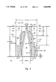
- FIG. 7 illustrates a mask placed over the slider depicted in FIG. 6 in accordance with a preferred embodiment of the present invention.
- Disk drive 110 includes housing 112, and housing cover 114 which, after assembly, is mounted within frame 116.
- Rotatably attached within housing 112 on actuator shaft 118 is actuator arm assembly 120.
- One end of actuator arm assembly 120 includes an E block or comb-like structure 122 having arms 123. Attached to arms 123 on the comb-like or E block structure 122, are suspension units or load springs 124. Attached at the end of each load spring is a slider 126, which carries a electromagnetic device for reading and/or writing data.
- a voice coil 128 On the other end of actuator arm assembly 120, opposite load springs 124 and sliders 126, is a voice coil 128.
- Magnets 130 and voice coil 128 are key parts of a voice coil motor which apply a force to actuator assembly 120 to rotate it about actuator shaft 118.
- spindle shaft 132 is mounted within housing 112.
- Rotatably attached to spindle shaft 132 are a number of disks 134. In FIG. 2, eight disks are attached to spindle shaft 132. As shown in FIG. 2, disks 134 are attached to spindle shaft 132 in spaced apart relation.
- An internal motor (not shown) is utilized to rotate disks 134.
- a wafer 50 is depicted which may be constructed of any suitable and well known slider material such as ferrite, Al 2 O 3 -TiC, or the like. Wafer 50 may be of any convenient size, such as four inches or six inches in diameter. Electromagnetic devices (not shown) are formed in wafer 50. Specifically, wafer 50 is a matrix of sliders 10, which when fully processed will become sliders, such as slider 10 which is illustrated in FIG. 2C.
- Wafer 50 may be fabricated to contain any desirable number of rows of sliders 10 in each row.
- Wafer 26 depicted in FIG. 2A contains 14 sliders 10 in each row.
- wafer 50 may be broken up into rows as shown in FIG. 2B for processing in accordance with a preferred embodiment of the present invention.
- FIG. 2C depicts a slider 10 from the row of sliders 10 in FIG. 2B.
- Top surface 8 of slider 10 has three rails 12, 14, and 16. Rail 12 is adjacent to side 7, and rail 16 is adjacent to side 9. Recessed sections 18 and 20 are found between the rails. Rails 12, 14, and 16 are typically 6 ⁇ m to 20 ⁇ m above recessed sections 18 and 20. Rails 12, 14, and 16 have air bearing surfaces (ABSs) 22, 24, and 26. Leading edge 28 of slider 10 includes tapered sections 30, 31 and 32. Slider 10 includes electromagnetic devices 23, which are used to detect data on a magnetic media, as depicted on the side of back edge 27 of slider 10.
- the crown of slider 10 is a measurement of a rail, 12, 14, or 16.
- the crown is defined as the peak-to-valley difference of a cylindrical arch.
- the cylindrical arch is taken from the back edge 27 on rail 14 to the beginning of taper 31 of rail 14.
- profile data of the rail is taken and any tilt of the rail is subtracted from the profile data.
- the profile data is then fitted to an x-squared curve.
- the x-squared curve is then utilized to calculate the peak-to-valley difference across the crown of the rail.
- the "camber" of slider 10 is the curvature measured from side 7 to side 9.
- the camber is measured from the profile data of the rails 12, 14, and 16.
- the camber is also fitted to a x-squared curve from the profile data of the three rails measured from side 7 to side 9.
- FIG. 3A a top view of slider 10 from FIG. 2C is illustrated.
- a mask 54 is placed over slider 10 in FIG. 3B.
- Mask 54 has a leading edge 56 and a trailing edge 58.
- Mask 54 includes apertures 60 and 62.
- a stream of particles travelling at a selected velocity are directed at apertures 60 and 62 to induce compressive stress in the exposed regions of slider 10.
- Nozzle 64 propels a stream of particles 66 into aperture 60 of mask 54.
- These particles "sandblast” or “shot peen” the exposed surfaces of slider 10. Particles in the stream may penetrate and damage the grain boundaries of the material forming the wafer. The surface may open up and attempt to spread out.
- Raised surfaces of about 20 nm may occur as a result of "sandblasting" or “shot peening” the exposed surfaces.
- the particles preferably have jagged or rough surfaces.
- Materials such as aluminum oxide or silicon carbide may be employed in accordance with a preferred embodiment of the present invention.
- the particles should be hard enough such that the surface of the wafer can be damaged by the particles. Additionally, it is desirable to employ particles that are stable, economical, and non-toxic.
- the size of the particles should be small enough to enter the apertures created in the mask.
- a particle size from about 20 ⁇ m to about 75 ⁇ m in diameter may be employed in accordance with a preferred embodiment of the present invention.
- 50 micron aluminum oxide and 50 micron silicon carbide are examples of abrasive particles, which may be employed in accordance with a preferred embodiment of the present invention. These abrasive particles may be obtained from Crystal Mark, Inc., located in Glendale, Calif.
- slider 10 is depicted with sand blasted regions 72 and 74 and a resultant crown.
- FIGS. 4A-4C illustrate examples of masks with different aperture dimensions that may be utilized to alter the curvature of a slider.
- mask 76 contains two rectangular apertures 78 and 80 that are aligned with recessed regions in slider 10. Front edge 56 is aligned with leading edge 28 of the slider 10. This mask shape and orientation results in a crown change that is greater than the camber change. If a change in camber is desired, a mask such as mask 82 illustrated in FIG. 4B should be employed.
- Mask 82 is similar to mask 76 except that apertures 84 and 86 are formed such that they are wider than they are long.
- the apertures may be of any geometry, as shown by apertures 85 and 87 in mask 88 in FIG. 4C.
- the camber of a slider may be adjusted.
- the exposed regions on a slider impinged by the particles should be within the recessed regions found between rails in accordance with a preferred embodiment of the present invention.
- the apertures in the mask may expose any region on the slider, excluding the rails.
- a distance from 40 ⁇ m to 50 ⁇ m from the edge of the rails should not be exposed by the mask when the rails are excluded, in accordance with a preferred embodiment of the present invention.
- the mask may be fabricated from a number of different materials.
- the mask is fabricated from Al 2 O 3 -TiC and apertures in the mask may be created using a YAG laser.
- Other materials, such as metal or metal alloys also may be employed.
- the tapered sections of a slider are typically not “sandblasted” or “shot peened” by particles because damaging the surface of the slider in these sections will not effect the curvature of the slider to any appreciable amount.
- a positive change in camber or crown may be introduced. Reduction of camber or crown in a slider may be achieved by exposing regions on the back side of the slider and applying a stream of particles to the bottom surface of the slider. In fact, a negative crown or camber may be made by impinging the bottom surface of the slider with a stream of particles. Thus, increases and decreases in slider curvatures may be accomplished by impinging the top or bottom surface of the slider.
- the depicted slider is a three rail slider, other configurations and types of sliders, such as a two rail slider, may be manufactured using the process according to the present invention.
- FIG. 5 a graph of slider crown correction showing the change in crown versus the velocity is depicted.
- the delta crown (nm) is illustrated in relation to the velocity (in/sec) of a nozzle moving over and past the apertures of a mask.
- abrasive powder 50 micron aluminum oxide available from Crystal Mark, Inc., located in Glendale, Calif.
- a microprocessor controlled nozzle positioner, a SWAM-NOZ POZ, available from Crystal Mark, Inc. was used along with a rectangular abrasive nozzle, part number 353-125X, having a nozzle size of 0.006 inches by 0.100 inches available from Crystal Mark, Inc. was employed.
- the nozzle was positioned a distance of 2.5 mm from the nozzle tip to mask and the aluminum oxide was forced through the nozzle under a pressure of 60 pounds per square inch (psi).
- the changes in crown for different nozzle velocities are shown in FIG. 5.
- the stream of particles was directed at the top surface of the slider providing a positive change or increase in the crown of the slider.
- FIG. 6 is a top view of a slider 10 processed as described above with reference to FIG. 6.
- the rails are 20 ⁇ m above the recessed sections.
- Sections 90 and 92 are areas that were exposed to the stream of 50 micron aluminum oxide particles forced through the nozzle under a pressure of 60 psi. As can be seen, a margin of at least 0.050 mm or 50 ⁇ m was maintained between the exposed areas and the rails.
- FIG. 7 illustrates a mask that was placed over the slider illustrated in FIG. 6. In practice, a mask including multiple sets of apertures, such as that depicted in FIG.
- the microprocessor controlled nozzle positioner can be programmed to change the velocity of the nozzle as it passes from one set of apertures for one slider to the next set of apertures so that the sliders can all be selectively corrected to the same crown even though the original crowns may be different.
- slider units would be processed in rows selected from a wafer, as shown in FIG. 2B.
- the nozzle would scan over a row at a selected velocity to produce the desired change in crown.
- the depicted example employs a nozzle scanning over a row of sliders
- other methods of propelling particles may be utilized in accordance with a preferred embodiment of the present invention.
- a nozzle may be positioned over an individual slider and a stream of particles may be forced through the nozzle for a selected amount of time on to the regions exposed by the apertures in the mask.
- the crown or camber of the slider also may be altered up to the point that the slider is suspended on the spring or suspension unit that is mounted on the actuator arm.
Abstract
Description
Claims (26)
Priority Applications (4)
| Application Number | Priority Date | Filing Date | Title |
|---|---|---|---|
| US08/146,552 US5442850A (en) | 1993-11-01 | 1993-11-01 | Magnetic head slider process |
| JP6236143A JP2739039B2 (en) | 1993-11-01 | 1994-09-30 | Method of manufacturing slider |
| SG1996004999A SG46481A1 (en) | 1993-11-01 | 1994-10-27 | Magnetic head slider fabrication |
| GB9421714A GB2283610B (en) | 1993-11-01 | 1994-10-27 | Magnetic head slider fabrication |
Applications Claiming Priority (1)
| Application Number | Priority Date | Filing Date | Title |
|---|---|---|---|
| US08/146,552 US5442850A (en) | 1993-11-01 | 1993-11-01 | Magnetic head slider process |
Publications (1)
| Publication Number | Publication Date |
|---|---|
| US5442850A true US5442850A (en) | 1995-08-22 |
Family
ID=22517902
Family Applications (1)
| Application Number | Title | Priority Date | Filing Date |
|---|---|---|---|
| US08/146,552 Expired - Lifetime US5442850A (en) | 1993-11-01 | 1993-11-01 | Magnetic head slider process |
Country Status (4)
| Country | Link |
|---|---|
| US (1) | US5442850A (en) |
| JP (1) | JP2739039B2 (en) |
| GB (1) | GB2283610B (en) |
| SG (1) | SG46481A1 (en) |
Cited By (34)
| Publication number | Priority date | Publication date | Assignee | Title |
|---|---|---|---|---|
| US5548886A (en) * | 1993-08-31 | 1996-08-27 | Sony Corporation | Method of manufacturing floating magnetic head device |
| US5704112A (en) * | 1992-05-29 | 1998-01-06 | Tdk Corporation | Method of manufacturing a magnetic head |
| US5713123A (en) * | 1994-06-03 | 1998-02-03 | Yamaha Corporation | Method of lapping for producing one-side curved surface adapted for floating magnetic head |
| US5768053A (en) * | 1995-08-04 | 1998-06-16 | Tdk Corporation | Flying magnetic head slider |
| US5835305A (en) * | 1993-12-07 | 1998-11-10 | Hitachi, Ltd. | Magnetic disk apparatus employing liquid bearing type or physical contact type magnetic head slider |
| WO1999009549A1 (en) * | 1997-08-15 | 1999-02-25 | Seagate Technology, Inc. | Textured work-hardened magnetic media and their fabrication |
| US5982583A (en) * | 1996-06-12 | 1999-11-09 | Seagate Technology, Inc. | Slider having thermally applied tensile stress for curvature control and method of applying tensile stress |
| US6073337A (en) * | 1996-06-12 | 2000-06-13 | Seagate Technology, Inc. | Compressive stress treatment method for controlling curvature of a hydrodynamic bearing slider |
| US6118634A (en) * | 1993-11-17 | 2000-09-12 | Sony Corporation | Flying type head slider and disk drive apparatus with the flying tape head slider |
| US6166879A (en) * | 1996-10-31 | 2000-12-26 | Aiwa Co., Ltd. | Thin film magnetic head with contoured surface |
| US6288873B1 (en) | 1999-10-18 | 2001-09-11 | International Business Machines Corporation | Curvature adjustment of sliders by scribing of slider suspension |
| US6312313B1 (en) | 1999-10-06 | 2001-11-06 | Intenational Business Machines Corporation | Non-linear transducer lay-out of thin film head wafer for fabrication of high camber and crown sliders |
| US6321440B1 (en) * | 1998-11-10 | 2001-11-27 | International Business Machines Corporation | Method for adjusting curvature of magnetic read/write head sliders |
| US6356412B1 (en) * | 1999-09-30 | 2002-03-12 | Read-Rite Corporation | Air bearing facilitating load/unload of a magnetic read/write head |
| US6419566B1 (en) | 2000-02-11 | 2002-07-16 | International Business Machines Corporation | System for cleaning contamination from magnetic recording media rows |
| US6441385B1 (en) | 2000-04-06 | 2002-08-27 | Seagate Technology, Llc. | Method and apparatus for optimizing adjustment of disc head slider curvature |
| US6466407B1 (en) | 1996-08-07 | 2002-10-15 | Seagate Technology, Llc. | Method and apparatus for applying an information pattern to a disc head slider |
| US6501048B1 (en) | 1996-06-12 | 2002-12-31 | Seagate Technology Llc | Slider having thermally applied tensile stress for curvature control and method of applying tensile stress |
| US20030021067A1 (en) * | 2001-07-27 | 2003-01-30 | Ping-Wei Chang | Control of twist, crown and camber for sliders using location sensitive scribing |
| US6548009B1 (en) | 1996-06-12 | 2003-04-15 | Seagate Technology Llc | Method for controlling twist curvature of a disc head slider |
| US6589436B1 (en) | 2000-06-14 | 2003-07-08 | International Business Machines Corporation | Method of adjusting the flatness of a slider using selective plasma etching |
| US20030174444A1 (en) * | 2002-03-12 | 2003-09-18 | Youping Mei | Method and apparatus for controlling shape of a bearing surface of a slider |
| US6631548B2 (en) | 2001-07-27 | 2003-10-14 | International Business Machines Corporation | Simultaneous slider crown and camber adjust by scribe line control |
| US6662069B1 (en) * | 2000-04-06 | 2003-12-09 | Seagate Technology Llc | Slider having independently controlled crown and cross curvature and method of controlling curvature |
| US6663817B1 (en) | 1999-03-26 | 2003-12-16 | Hitachi Global Storage Technologies Netherlands, B.V. | Method for manufacture of sliders |
| US20040050831A1 (en) * | 2000-06-15 | 2004-03-18 | Tam Andrew Ching | Slider produced by slider curvature modification by substrate melting produced with a pulsed laser beam |
| US6747845B1 (en) * | 2000-10-11 | 2004-06-08 | International Business Machines Corporation | Modified strain region of strain reactive slider with implanted ions, electrons or neutral atoms |
| US20050047017A1 (en) * | 2003-08-14 | 2005-03-03 | Seagate Technology Llc | Slider having adjusted transducer recession and method of adjusting recession |
| US6888701B2 (en) | 2001-07-27 | 2005-05-03 | Hitachi Global Storage Technologies Netherlands B.V. | Enhanced twist adjust range with scribed lines for slider curvature adjust |
| US20050118934A1 (en) * | 2001-05-18 | 2005-06-02 | Sae Magnetics(H.K.) Ltd. | Method for shaping air bearing surface of magnetic head slider and manufacturing method of magnetic head slider |
| US20050190501A1 (en) * | 2000-07-28 | 2005-09-01 | Seagate Technology Llc | AAB having cavities for increasing contact stiffness and controlling suction center movement |
| US7124497B1 (en) | 2003-08-18 | 2006-10-24 | Seagate Technology Llc | Method of controlling localized shape of a data head and for characterizing the shape |
| US9202495B2 (en) | 2007-05-01 | 2015-12-01 | Seagate Technology Llc | Method and apparatus for detecting proximity contact between a transducer and a medium |
| US9704523B1 (en) | 2016-01-07 | 2017-07-11 | Western Digital Technologies, Inc. | Slider with tunnel feature |
Citations (11)
| Publication number | Priority date | Publication date | Assignee | Title |
|---|---|---|---|---|
| US3685216A (en) * | 1970-01-14 | 1972-08-22 | Honeywell Inc | Slider bearing surface generation |
| US4333229A (en) * | 1980-07-21 | 1982-06-08 | Memorex Corporation | Method of manufacturing thin film magnetic head/slider combination |
| US4420780A (en) * | 1981-08-17 | 1983-12-13 | International Business Machines | Self-loading magnetic head air bearing slider |
| JPH0195343A (en) * | 1987-10-07 | 1989-04-13 | Matsushita Electric Ind Co Ltd | Storage |
| US4870521A (en) * | 1988-06-23 | 1989-09-26 | Kyocera Corporation | Floating magnetic head |
| US4910621A (en) * | 1987-02-09 | 1990-03-20 | Kabushiki Kaisha Toshiba | Magnetic head device having sloped sliding surface which is formed thermally curved |
| US4939603A (en) * | 1986-11-06 | 1990-07-03 | Mitsubishi Denki Kabushiki Kaisha | Magnetic head slider having a convex taper surface with the curvature facing a magnetic medium |
| US5065500A (en) * | 1985-09-05 | 1991-11-19 | Canon Kabushiki Kaisha | Method of manufacturing a magnetic head assembly including a magnetic recording medium slide surface having grooves formed thereon |
| US5083365A (en) * | 1987-06-22 | 1992-01-28 | Mitsubishi Denki K. K. | Process for manufacturing a magnetic head |
| US5095613A (en) * | 1990-06-29 | 1992-03-17 | Digital Equipment Corporation | Thin film head slider fabrication process |
| US5136445A (en) * | 1990-08-31 | 1992-08-04 | Seagate Technology, Inc. | Air bearing slider design |
Family Cites Families (9)
| Publication number | Priority date | Publication date | Assignee | Title |
|---|---|---|---|---|
| JPH02108291A (en) * | 1988-10-18 | 1990-04-20 | Hitachi Metals Ltd | Floating type magnetic head |
| JP2940023B2 (en) * | 1989-10-30 | 1999-08-25 | ソニー株式会社 | Processing method using loose abrasive |
| JPH043378A (en) * | 1990-04-20 | 1992-01-08 | Sony Corp | Slider face working method for floating head slider |
| JPH04167279A (en) * | 1990-10-30 | 1992-06-15 | Kyocera Corp | Levitation type magnetic head |
| JPH04259971A (en) * | 1991-02-15 | 1992-09-16 | Sony Corp | Surface working method for slider for head |
| JP2859468B2 (en) * | 1991-07-09 | 1999-02-17 | アルプス電気株式会社 | Magnetic head and method of manufacturing magnetic head |
| US5266769A (en) * | 1992-02-25 | 1993-11-30 | International Business Machines Corporation | Process for independent control of crown and camber for magnetic head slider |
| CA2082119A1 (en) * | 1992-02-25 | 1993-08-26 | Annayya Pralhadrao Deshpande | Process for independent control of crown and camber for magnetic head slider |
| JPH0724096B2 (en) * | 1992-05-29 | 1995-03-15 | ティーディーケイ株式会社 | Magnetic head processing method |
-
1993
- 1993-11-01 US US08/146,552 patent/US5442850A/en not_active Expired - Lifetime
-
1994
- 1994-09-30 JP JP6236143A patent/JP2739039B2/en not_active Expired - Fee Related
- 1994-10-27 SG SG1996004999A patent/SG46481A1/en unknown
- 1994-10-27 GB GB9421714A patent/GB2283610B/en not_active Expired - Fee Related
Patent Citations (11)
| Publication number | Priority date | Publication date | Assignee | Title |
|---|---|---|---|---|
| US3685216A (en) * | 1970-01-14 | 1972-08-22 | Honeywell Inc | Slider bearing surface generation |
| US4333229A (en) * | 1980-07-21 | 1982-06-08 | Memorex Corporation | Method of manufacturing thin film magnetic head/slider combination |
| US4420780A (en) * | 1981-08-17 | 1983-12-13 | International Business Machines | Self-loading magnetic head air bearing slider |
| US5065500A (en) * | 1985-09-05 | 1991-11-19 | Canon Kabushiki Kaisha | Method of manufacturing a magnetic head assembly including a magnetic recording medium slide surface having grooves formed thereon |
| US4939603A (en) * | 1986-11-06 | 1990-07-03 | Mitsubishi Denki Kabushiki Kaisha | Magnetic head slider having a convex taper surface with the curvature facing a magnetic medium |
| US4910621A (en) * | 1987-02-09 | 1990-03-20 | Kabushiki Kaisha Toshiba | Magnetic head device having sloped sliding surface which is formed thermally curved |
| US5083365A (en) * | 1987-06-22 | 1992-01-28 | Mitsubishi Denki K. K. | Process for manufacturing a magnetic head |
| JPH0195343A (en) * | 1987-10-07 | 1989-04-13 | Matsushita Electric Ind Co Ltd | Storage |
| US4870521A (en) * | 1988-06-23 | 1989-09-26 | Kyocera Corporation | Floating magnetic head |
| US5095613A (en) * | 1990-06-29 | 1992-03-17 | Digital Equipment Corporation | Thin film head slider fabrication process |
| US5136445A (en) * | 1990-08-31 | 1992-08-04 | Seagate Technology, Inc. | Air bearing slider design |
Non-Patent Citations (6)
| Title |
|---|
| IBM Confidential Document Disclosure, Docket No. SA990069, Jun. 1992, "A Process For The Control Of Crown And Camber" A. P. Deshpande et al. |
| IBM Confidential Document Disclosure, Docket No. SA990069, Jun. 1992, A Process For The Control Of Crown And Camber A. P. Deshpande et al. * |
| International Technology Disclosures v2 n3 Mar. 1984, W. Jacobs "Method For Pre-Stressing Row Tp Achieve Positive Crown Air Bearing Slider". |
| International Technology Disclosures v2 n3 Mar. 1984, W. Jacobs Method For Pre Stressing Row Tp Achieve Positive Crown Air Bearing Slider . * |
| Research Disclosure n253 May 1985, A. F. Diaz & C. R. Jih "Fabrication Process for Crown Sliders". |
| Research Disclosure n253 May 1985, A. F. Diaz & C. R. Jih Fabrication Process for Crown Sliders . * |
Cited By (50)
| Publication number | Priority date | Publication date | Assignee | Title |
|---|---|---|---|---|
| US5704112A (en) * | 1992-05-29 | 1998-01-06 | Tdk Corporation | Method of manufacturing a magnetic head |
| US5548886A (en) * | 1993-08-31 | 1996-08-27 | Sony Corporation | Method of manufacturing floating magnetic head device |
| US6118634A (en) * | 1993-11-17 | 2000-09-12 | Sony Corporation | Flying type head slider and disk drive apparatus with the flying tape head slider |
| US5835305A (en) * | 1993-12-07 | 1998-11-10 | Hitachi, Ltd. | Magnetic disk apparatus employing liquid bearing type or physical contact type magnetic head slider |
| US5713123A (en) * | 1994-06-03 | 1998-02-03 | Yamaha Corporation | Method of lapping for producing one-side curved surface adapted for floating magnetic head |
| US5768053A (en) * | 1995-08-04 | 1998-06-16 | Tdk Corporation | Flying magnetic head slider |
| US6501048B1 (en) | 1996-06-12 | 2002-12-31 | Seagate Technology Llc | Slider having thermally applied tensile stress for curvature control and method of applying tensile stress |
| US6784398B2 (en) | 1996-06-12 | 2004-08-31 | Seagate Technology Llc | Apparatus for controlling twist curvature of a disc head slider |
| US5982583A (en) * | 1996-06-12 | 1999-11-09 | Seagate Technology, Inc. | Slider having thermally applied tensile stress for curvature control and method of applying tensile stress |
| US6548009B1 (en) | 1996-06-12 | 2003-04-15 | Seagate Technology Llc | Method for controlling twist curvature of a disc head slider |
| US6073337A (en) * | 1996-06-12 | 2000-06-13 | Seagate Technology, Inc. | Compressive stress treatment method for controlling curvature of a hydrodynamic bearing slider |
| US6295719B1 (en) | 1996-06-12 | 2001-10-02 | Seagate Technology Llc | Compressive stress treatment method for controlling curvature of a hydrodynamic bearing slider |
| US6466407B1 (en) | 1996-08-07 | 2002-10-15 | Seagate Technology, Llc. | Method and apparatus for applying an information pattern to a disc head slider |
| US6567241B2 (en) | 1996-08-07 | 2003-05-20 | Seagate Technology Llc | Disc head slider having a film representing and information pattern |
| US6166879A (en) * | 1996-10-31 | 2000-12-26 | Aiwa Co., Ltd. | Thin film magnetic head with contoured surface |
| WO1999009549A1 (en) * | 1997-08-15 | 1999-02-25 | Seagate Technology, Inc. | Textured work-hardened magnetic media and their fabrication |
| US6321440B1 (en) * | 1998-11-10 | 2001-11-27 | International Business Machines Corporation | Method for adjusting curvature of magnetic read/write head sliders |
| US6663817B1 (en) | 1999-03-26 | 2003-12-16 | Hitachi Global Storage Technologies Netherlands, B.V. | Method for manufacture of sliders |
| US6583961B2 (en) | 1999-09-30 | 2003-06-24 | Read-Rite Corporation | Air bearing facilitating load/unload of a magnetic read/write head |
| US6356412B1 (en) * | 1999-09-30 | 2002-03-12 | Read-Rite Corporation | Air bearing facilitating load/unload of a magnetic read/write head |
| US6312313B1 (en) | 1999-10-06 | 2001-11-06 | Intenational Business Machines Corporation | Non-linear transducer lay-out of thin film head wafer for fabrication of high camber and crown sliders |
| US6288873B1 (en) | 1999-10-18 | 2001-09-11 | International Business Machines Corporation | Curvature adjustment of sliders by scribing of slider suspension |
| US6419566B1 (en) | 2000-02-11 | 2002-07-16 | International Business Machines Corporation | System for cleaning contamination from magnetic recording media rows |
| US6662069B1 (en) * | 2000-04-06 | 2003-12-09 | Seagate Technology Llc | Slider having independently controlled crown and cross curvature and method of controlling curvature |
| US6441385B1 (en) | 2000-04-06 | 2002-08-27 | Seagate Technology, Llc. | Method and apparatus for optimizing adjustment of disc head slider curvature |
| US6627909B2 (en) | 2000-04-06 | 2003-09-30 | Seagate Technology Llc | Apparatus for optimizing adjustment of disc head slider curvature |
| US6589436B1 (en) | 2000-06-14 | 2003-07-08 | International Business Machines Corporation | Method of adjusting the flatness of a slider using selective plasma etching |
| US20050173389A1 (en) * | 2000-06-15 | 2005-08-11 | Tam Andrew C. | Apparatus for slider curvature modification by substrate melting produced with a pulsed laser beam |
| US20040050831A1 (en) * | 2000-06-15 | 2004-03-18 | Tam Andrew Ching | Slider produced by slider curvature modification by substrate melting produced with a pulsed laser beam |
| US6710295B1 (en) | 2000-06-15 | 2004-03-23 | Hitachi Global Storage Technologies Netherlands, B.V. | Slider curvature modification by substrate melting effect produced with a pulsed laser beam |
| US6831249B2 (en) | 2000-06-15 | 2004-12-14 | Hitachi Global Storage Technologies Netherlands B.V. | Slider produced by slider curvature modification by substrate melting produced with a pulsed laser beam |
| US7209323B2 (en) | 2000-07-28 | 2007-04-24 | Seagate Technology Llc | Slider having cavity floor with differing depths |
| US20050190501A1 (en) * | 2000-07-28 | 2005-09-01 | Seagate Technology Llc | AAB having cavities for increasing contact stiffness and controlling suction center movement |
| US7566483B2 (en) * | 2000-10-11 | 2009-07-28 | Hitachi Global Storage Technologies Netherlands, B.V. | Particle irradiation method for modification of local strain in strain reactive structures |
| US6747845B1 (en) * | 2000-10-11 | 2004-06-08 | International Business Machines Corporation | Modified strain region of strain reactive slider with implanted ions, electrons or neutral atoms |
| US20040224092A1 (en) * | 2000-10-11 | 2004-11-11 | John Edward Eric Baglin | Particle irradiation method for modification of local strain in strain reactive structures |
| US20050118934A1 (en) * | 2001-05-18 | 2005-06-02 | Sae Magnetics(H.K.) Ltd. | Method for shaping air bearing surface of magnetic head slider and manufacturing method of magnetic head slider |
| US7185417B2 (en) * | 2001-05-18 | 2007-03-06 | Sae Magnetics (H.K.) Ltd. | Method for shaping an air bearing surface of a magnetic head slider |
| US6888701B2 (en) | 2001-07-27 | 2005-05-03 | Hitachi Global Storage Technologies Netherlands B.V. | Enhanced twist adjust range with scribed lines for slider curvature adjust |
| US6631548B2 (en) | 2001-07-27 | 2003-10-14 | International Business Machines Corporation | Simultaneous slider crown and camber adjust by scribe line control |
| US20030021067A1 (en) * | 2001-07-27 | 2003-01-30 | Ping-Wei Chang | Control of twist, crown and camber for sliders using location sensitive scribing |
| US20030174444A1 (en) * | 2002-03-12 | 2003-09-18 | Youping Mei | Method and apparatus for controlling shape of a bearing surface of a slider |
| US20050047017A1 (en) * | 2003-08-14 | 2005-03-03 | Seagate Technology Llc | Slider having adjusted transducer recession and method of adjusting recession |
| US7212381B2 (en) | 2003-08-14 | 2007-05-01 | Seagate Technology Llc | Slider having adjusted transducer recession and method of adjusting recession |
| US7549212B2 (en) | 2003-08-14 | 2009-06-23 | Seagate Technology Llc | Method of adjusting recession of an element of a slider |
| US7124497B1 (en) | 2003-08-18 | 2006-10-24 | Seagate Technology Llc | Method of controlling localized shape of a data head and for characterizing the shape |
| US9202495B2 (en) | 2007-05-01 | 2015-12-01 | Seagate Technology Llc | Method and apparatus for detecting proximity contact between a transducer and a medium |
| US9704523B1 (en) | 2016-01-07 | 2017-07-11 | Western Digital Technologies, Inc. | Slider with tunnel feature |
| US9865284B2 (en) | 2016-01-07 | 2018-01-09 | Western Digital Technologies, Inc. | Fabrication process for slider with extended three-dimensional air-bearing surface |
| US9886976B2 (en) | 2016-01-07 | 2018-02-06 | Western Digital Technologies, Inc. | Slider with extended three-dimensional air-bearing surface |
Also Published As
| Publication number | Publication date |
|---|---|
| SG46481A1 (en) | 1998-02-20 |
| JPH07169034A (en) | 1995-07-04 |
| GB9421714D0 (en) | 1994-12-14 |
| JP2739039B2 (en) | 1998-04-08 |
| GB2283610A (en) | 1995-05-10 |
| GB2283610B (en) | 1998-03-11 |
Similar Documents
| Publication | Publication Date | Title |
|---|---|---|
| US5442850A (en) | Magnetic head slider process | |
| US5490025A (en) | Air bearing slider with debris deflecting features | |
| US6183349B1 (en) | Burnishing head with circular burnishing pads | |
| US6358123B1 (en) | Apparatus and method for reducing disc surface asperities to sub-microinch height | |
| US5086360A (en) | Constant flying height slider | |
| US7969688B2 (en) | Method and apparatus supporting a slider having multiple deflection rails in a negative pressure pocket for a hard disk drive | |
| US6483667B1 (en) | Self-loading disc head slider having multiple steps approximating a leading taper | |
| US6073337A (en) | Compressive stress treatment method for controlling curvature of a hydrodynamic bearing slider | |
| US7009813B2 (en) | Apparatus and method of configuring the air bearing surfaces of sliders in disk drives for producing high temperatures in thermally-assisted recordings | |
| US6264787B1 (en) | Apparatus for fabricating a taper on a recording head slider | |
| EP0710957A1 (en) | Air bearing slider and method of manufacture therefor | |
| US11114121B2 (en) | Air-bearing surface (ABS) design to reduce particle scratch risk | |
| US6243222B1 (en) | Load/unload method for sliders in a high speed disk drive | |
| US7450343B2 (en) | Device, apparatus and method for removing particulate contamination from the trailing edge of a hard disk drive air bearing | |
| US20020071216A1 (en) | Disc drive having an air bearing surface with trenched contact protection feature | |
| JP2006505888A (en) | Method and apparatus for processing sliders used in disk drives and the like | |
| US6731463B2 (en) | Wafer fabrication for thermal pole tip expansion/recession compensation | |
| US5726830A (en) | Air-bearing electromagnetic head slider having negative pressure generating means | |
| US20040150915A1 (en) | Air bearing surface for a head, and a method of making it | |
| US6205002B1 (en) | Disk drive with textured slider contact region | |
| US6080043A (en) | Apparatus and method for achieving positive crown during ABS lap | |
| CA2123436A1 (en) | Thin film transducer with reduced flying height | |
| JP2808208B2 (en) | Manufacturing method of magnetic head | |
| US20090231759A1 (en) | Head slider, head assembly and information storage device | |
| US6312313B1 (en) | Non-linear transducer lay-out of thin film head wafer for fabrication of high camber and crown sliders |
Legal Events
| Date | Code | Title | Description |
|---|---|---|---|
| AS | Assignment |
Owner name: INTERNATIONAL BUSINESS MACHINES CORPORATION, NEW Y Free format text: ASSIGNMENT OF ASSIGNORS INTEREST;ASSIGNOR:KERTH, RANDALL THOMAS;REEL/FRAME:006762/0810 Effective date: 19931101 |
|
| STCF | Information on status: patent grant |
Free format text: PATENTED CASE |
|
| FPAY | Fee payment |
Year of fee payment: 4 |
|
| FPAY | Fee payment |
Year of fee payment: 8 |
|
| AS | Assignment |
Owner name: MARIANA HDD B.V., NETHERLANDS Free format text: ASSIGNMENT OF ASSIGNORS INTEREST;ASSIGNOR:INTERNATIONAL BUSINESS MACHINES CORPORATION;REEL/FRAME:013663/0348 Effective date: 20021231 |
|
| AS | Assignment |
Owner name: HITACHI GLOBAL STORAGE TECHNOLOGIES NETHERLANDS B. Free format text: CHANGE OF NAME;ASSIGNOR:MARIANA HDD B.V.;REEL/FRAME:013746/0146 Effective date: 20021231 |
|
| FEPP | Fee payment procedure |
Free format text: PAYOR NUMBER ASSIGNED (ORIGINAL EVENT CODE: ASPN); ENTITY STATUS OF PATENT OWNER: LARGE ENTITY |
|
| FPAY | Fee payment |
Year of fee payment: 12 |
|
| AS | Assignment |
Owner name: HGST, NETHERLANDS B.V., NETHERLANDS Free format text: CHANGE OF NAME;ASSIGNOR:HGST, NETHERLANDS B.V.;REEL/FRAME:029341/0777 Effective date: 20120723 Owner name: HGST NETHERLANDS B.V., NETHERLANDS Free format text: CHANGE OF NAME;ASSIGNOR:HITACHI GLOBAL STORAGE TECHNOLOGIES NETHERLANDS B.V.;REEL/FRAME:029341/0777 Effective date: 20120723 |