US5447586A - Control of thermoplastic tow placement - Google Patents
Control of thermoplastic tow placement Download PDFInfo
- Publication number
- US5447586A US5447586A US08/273,684 US27368494A US5447586A US 5447586 A US5447586 A US 5447586A US 27368494 A US27368494 A US 27368494A US 5447586 A US5447586 A US 5447586A
- Authority
- US
- United States
- Prior art keywords
- temperature
- velocity
- tow
- laydown
- set point
- Prior art date
- Legal status (The legal status is an assumption and is not a legal conclusion. Google has not performed a legal analysis and makes no representation as to the accuracy of the status listed.)
- Expired - Lifetime
Links
- 229920001169 thermoplastic Polymers 0.000 title 1
- 239000004416 thermosoftening plastic Substances 0.000 title 1
- 238000000034 method Methods 0.000 claims abstract description 42
- 239000002131 composite material Substances 0.000 claims abstract description 13
- 238000010438 heat treatment Methods 0.000 claims description 10
- 239000000835 fiber Substances 0.000 claims description 4
- 229920005992 thermoplastic resin Polymers 0.000 claims description 3
- 238000001816 cooling Methods 0.000 claims description 2
- 230000013011 mating Effects 0.000 claims description 2
- 230000008569 process Effects 0.000 abstract description 33
- 238000006880 cross-coupling reaction Methods 0.000 abstract description 2
- 238000005056 compaction Methods 0.000 description 9
- 238000007596 consolidation process Methods 0.000 description 7
- 238000012546 transfer Methods 0.000 description 6
- 238000004364 calculation method Methods 0.000 description 5
- 229920000642 polymer Polymers 0.000 description 5
- 238000011065 in-situ storage Methods 0.000 description 3
- 230000001788 irregular Effects 0.000 description 3
- 230000004044 response Effects 0.000 description 3
- 239000000758 substrate Substances 0.000 description 3
- 230000008859 change Effects 0.000 description 2
- 238000009730 filament winding Methods 0.000 description 2
- 239000010410 layer Substances 0.000 description 2
- 238000004519 manufacturing process Methods 0.000 description 2
- 239000000463 material Substances 0.000 description 2
- 238000004458 analytical method Methods 0.000 description 1
- 238000013459 approach Methods 0.000 description 1
- 238000010420 art technique Methods 0.000 description 1
- 230000015556 catabolic process Effects 0.000 description 1
- 238000005094 computer simulation Methods 0.000 description 1
- 238000006731 degradation reaction Methods 0.000 description 1
- 238000010586 diagram Methods 0.000 description 1
- 239000003733 fiber-reinforced composite Substances 0.000 description 1
- 230000004907 flux Effects 0.000 description 1
- 238000005259 measurement Methods 0.000 description 1
- 239000000155 melt Substances 0.000 description 1
- 230000006903 response to temperature Effects 0.000 description 1
- 239000002344 surface layer Substances 0.000 description 1
- 230000001052 transient effect Effects 0.000 description 1
- 238000011144 upstream manufacturing Methods 0.000 description 1
- 238000004804 winding Methods 0.000 description 1
Images


Classifications
-
- B—PERFORMING OPERATIONS; TRANSPORTING
- B29—WORKING OF PLASTICS; WORKING OF SUBSTANCES IN A PLASTIC STATE IN GENERAL
- B29C—SHAPING OR JOINING OF PLASTICS; SHAPING OF MATERIAL IN A PLASTIC STATE, NOT OTHERWISE PROVIDED FOR; AFTER-TREATMENT OF THE SHAPED PRODUCTS, e.g. REPAIRING
- B29C65/00—Joining or sealing of preformed parts, e.g. welding of plastics materials; Apparatus therefor
- B29C65/02—Joining or sealing of preformed parts, e.g. welding of plastics materials; Apparatus therefor by heating, with or without pressure
- B29C65/18—Joining or sealing of preformed parts, e.g. welding of plastics materials; Apparatus therefor by heating, with or without pressure using heated tools
-
- B—PERFORMING OPERATIONS; TRANSPORTING
- B29—WORKING OF PLASTICS; WORKING OF SUBSTANCES IN A PLASTIC STATE IN GENERAL
- B29C—SHAPING OR JOINING OF PLASTICS; SHAPING OF MATERIAL IN A PLASTIC STATE, NOT OTHERWISE PROVIDED FOR; AFTER-TREATMENT OF THE SHAPED PRODUCTS, e.g. REPAIRING
- B29C35/00—Heating, cooling or curing, e.g. crosslinking or vulcanising; Apparatus therefor
- B29C35/02—Heating or curing, e.g. crosslinking or vulcanizing during moulding, e.g. in a mould
- B29C35/0288—Controlling heating or curing of polymers during moulding, e.g. by measuring temperatures or properties of the polymer and regulating the process
-
- B—PERFORMING OPERATIONS; TRANSPORTING
- B29—WORKING OF PLASTICS; WORKING OF SUBSTANCES IN A PLASTIC STATE IN GENERAL
- B29C—SHAPING OR JOINING OF PLASTICS; SHAPING OF MATERIAL IN A PLASTIC STATE, NOT OTHERWISE PROVIDED FOR; AFTER-TREATMENT OF THE SHAPED PRODUCTS, e.g. REPAIRING
- B29C53/00—Shaping by bending, folding, twisting, straightening or flattening; Apparatus therefor
- B29C53/80—Component parts, details or accessories; Auxiliary operations
- B29C53/8008—Component parts, details or accessories; Auxiliary operations specially adapted for winding and joining
- B29C53/8041—Measuring, controlling or regulating
-
- B—PERFORMING OPERATIONS; TRANSPORTING
- B29—WORKING OF PLASTICS; WORKING OF SUBSTANCES IN A PLASTIC STATE IN GENERAL
- B29C—SHAPING OR JOINING OF PLASTICS; SHAPING OF MATERIAL IN A PLASTIC STATE, NOT OTHERWISE PROVIDED FOR; AFTER-TREATMENT OF THE SHAPED PRODUCTS, e.g. REPAIRING
- B29C65/00—Joining or sealing of preformed parts, e.g. welding of plastics materials; Apparatus therefor
- B29C65/02—Joining or sealing of preformed parts, e.g. welding of plastics materials; Apparatus therefor by heating, with or without pressure
- B29C65/10—Joining or sealing of preformed parts, e.g. welding of plastics materials; Apparatus therefor by heating, with or without pressure using hot gases (e.g. combustion gases) or flames coming in contact with at least one of the parts to be joined
- B29C65/106—Joining or sealing of preformed parts, e.g. welding of plastics materials; Apparatus therefor by heating, with or without pressure using hot gases (e.g. combustion gases) or flames coming in contact with at least one of the parts to be joined using flames coming in contact with at least one of the parts to be joined
-
- B—PERFORMING OPERATIONS; TRANSPORTING
- B29—WORKING OF PLASTICS; WORKING OF SUBSTANCES IN A PLASTIC STATE IN GENERAL
- B29C—SHAPING OR JOINING OF PLASTICS; SHAPING OF MATERIAL IN A PLASTIC STATE, NOT OTHERWISE PROVIDED FOR; AFTER-TREATMENT OF THE SHAPED PRODUCTS, e.g. REPAIRING
- B29C65/00—Joining or sealing of preformed parts, e.g. welding of plastics materials; Apparatus therefor
- B29C65/02—Joining or sealing of preformed parts, e.g. welding of plastics materials; Apparatus therefor by heating, with or without pressure
- B29C65/18—Joining or sealing of preformed parts, e.g. welding of plastics materials; Apparatus therefor by heating, with or without pressure using heated tools
- B29C65/24—Joining or sealing of preformed parts, e.g. welding of plastics materials; Apparatus therefor by heating, with or without pressure using heated tools characterised by the means for heating the tool
- B29C65/30—Electrical means
- B29C65/305—Electrical means involving the use of cartridge heaters
-
- B—PERFORMING OPERATIONS; TRANSPORTING
- B29—WORKING OF PLASTICS; WORKING OF SUBSTANCES IN A PLASTIC STATE IN GENERAL
- B29C—SHAPING OR JOINING OF PLASTICS; SHAPING OF MATERIAL IN A PLASTIC STATE, NOT OTHERWISE PROVIDED FOR; AFTER-TREATMENT OF THE SHAPED PRODUCTS, e.g. REPAIRING
- B29C66/00—General aspects of processes or apparatus for joining preformed parts
- B29C66/01—General aspects dealing with the joint area or with the area to be joined
- B29C66/02—Preparation of the material, in the area to be joined, prior to joining or welding
- B29C66/024—Thermal pre-treatments
- B29C66/0242—Heating, or preheating, e.g. drying
-
- B—PERFORMING OPERATIONS; TRANSPORTING
- B29—WORKING OF PLASTICS; WORKING OF SUBSTANCES IN A PLASTIC STATE IN GENERAL
- B29C—SHAPING OR JOINING OF PLASTICS; SHAPING OF MATERIAL IN A PLASTIC STATE, NOT OTHERWISE PROVIDED FOR; AFTER-TREATMENT OF THE SHAPED PRODUCTS, e.g. REPAIRING
- B29C66/00—General aspects of processes or apparatus for joining preformed parts
- B29C66/40—General aspects of joining substantially flat articles, e.g. plates, sheets or web-like materials; Making flat seams in tubular or hollow articles; Joining single elements to substantially flat surfaces
- B29C66/41—Joining substantially flat articles ; Making flat seams in tubular or hollow articles
- B29C66/43—Joining a relatively small portion of the surface of said articles
- B29C66/432—Joining a relatively small portion of the surface of said articles for making tubular articles or closed loops, e.g. by joining several sheets ; for making hollow articles or hollow preforms
- B29C66/4322—Joining a relatively small portion of the surface of said articles for making tubular articles or closed loops, e.g. by joining several sheets ; for making hollow articles or hollow preforms by joining a single sheet to itself
-
- B—PERFORMING OPERATIONS; TRANSPORTING
- B29—WORKING OF PLASTICS; WORKING OF SUBSTANCES IN A PLASTIC STATE IN GENERAL
- B29C—SHAPING OR JOINING OF PLASTICS; SHAPING OF MATERIAL IN A PLASTIC STATE, NOT OTHERWISE PROVIDED FOR; AFTER-TREATMENT OF THE SHAPED PRODUCTS, e.g. REPAIRING
- B29C66/00—General aspects of processes or apparatus for joining preformed parts
- B29C66/40—General aspects of joining substantially flat articles, e.g. plates, sheets or web-like materials; Making flat seams in tubular or hollow articles; Joining single elements to substantially flat surfaces
- B29C66/41—Joining substantially flat articles ; Making flat seams in tubular or hollow articles
- B29C66/43—Joining a relatively small portion of the surface of said articles
- B29C66/432—Joining a relatively small portion of the surface of said articles for making tubular articles or closed loops, e.g. by joining several sheets ; for making hollow articles or hollow preforms
- B29C66/4329—Joining a relatively small portion of the surface of said articles for making tubular articles or closed loops, e.g. by joining several sheets ; for making hollow articles or hollow preforms the joint lines being transversal but non-orthogonal with respect to the axis of said tubular articles, i.e. being oblique
-
- B—PERFORMING OPERATIONS; TRANSPORTING
- B29—WORKING OF PLASTICS; WORKING OF SUBSTANCES IN A PLASTIC STATE IN GENERAL
- B29C—SHAPING OR JOINING OF PLASTICS; SHAPING OF MATERIAL IN A PLASTIC STATE, NOT OTHERWISE PROVIDED FOR; AFTER-TREATMENT OF THE SHAPED PRODUCTS, e.g. REPAIRING
- B29C66/00—General aspects of processes or apparatus for joining preformed parts
- B29C66/40—General aspects of joining substantially flat articles, e.g. plates, sheets or web-like materials; Making flat seams in tubular or hollow articles; Joining single elements to substantially flat surfaces
- B29C66/49—Internally supporting the, e.g. tubular, article during joining
-
- B—PERFORMING OPERATIONS; TRANSPORTING
- B29—WORKING OF PLASTICS; WORKING OF SUBSTANCES IN A PLASTIC STATE IN GENERAL
- B29C—SHAPING OR JOINING OF PLASTICS; SHAPING OF MATERIAL IN A PLASTIC STATE, NOT OTHERWISE PROVIDED FOR; AFTER-TREATMENT OF THE SHAPED PRODUCTS, e.g. REPAIRING
- B29C66/00—General aspects of processes or apparatus for joining preformed parts
- B29C66/70—General aspects of processes or apparatus for joining preformed parts characterised by the composition, physical properties or the structure of the material of the parts to be joined; Joining with non-plastics material
- B29C66/72—General aspects of processes or apparatus for joining preformed parts characterised by the composition, physical properties or the structure of the material of the parts to be joined; Joining with non-plastics material characterised by the structure of the material of the parts to be joined
- B29C66/721—Fibre-reinforced materials
-
- B—PERFORMING OPERATIONS; TRANSPORTING
- B29—WORKING OF PLASTICS; WORKING OF SUBSTANCES IN A PLASTIC STATE IN GENERAL
- B29C—SHAPING OR JOINING OF PLASTICS; SHAPING OF MATERIAL IN A PLASTIC STATE, NOT OTHERWISE PROVIDED FOR; AFTER-TREATMENT OF THE SHAPED PRODUCTS, e.g. REPAIRING
- B29C66/00—General aspects of processes or apparatus for joining preformed parts
- B29C66/70—General aspects of processes or apparatus for joining preformed parts characterised by the composition, physical properties or the structure of the material of the parts to be joined; Joining with non-plastics material
- B29C66/73—General aspects of processes or apparatus for joining preformed parts characterised by the composition, physical properties or the structure of the material of the parts to be joined; Joining with non-plastics material characterised by the intensive physical properties of the material of the parts to be joined, by the optical properties of the material of the parts to be joined, by the extensive physical properties of the parts to be joined, by the state of the material of the parts to be joined or by the material of the parts to be joined being a thermoplastic or a thermoset
- B29C66/739—General aspects of processes or apparatus for joining preformed parts characterised by the composition, physical properties or the structure of the material of the parts to be joined; Joining with non-plastics material characterised by the intensive physical properties of the material of the parts to be joined, by the optical properties of the material of the parts to be joined, by the extensive physical properties of the parts to be joined, by the state of the material of the parts to be joined or by the material of the parts to be joined being a thermoplastic or a thermoset characterised by the material of the parts to be joined being a thermoplastic or a thermoset
- B29C66/7392—General aspects of processes or apparatus for joining preformed parts characterised by the composition, physical properties or the structure of the material of the parts to be joined; Joining with non-plastics material characterised by the intensive physical properties of the material of the parts to be joined, by the optical properties of the material of the parts to be joined, by the extensive physical properties of the parts to be joined, by the state of the material of the parts to be joined or by the material of the parts to be joined being a thermoplastic or a thermoset characterised by the material of the parts to be joined being a thermoplastic or a thermoset characterised by the material of at least one of the parts being a thermoplastic
- B29C66/73921—General aspects of processes or apparatus for joining preformed parts characterised by the composition, physical properties or the structure of the material of the parts to be joined; Joining with non-plastics material characterised by the intensive physical properties of the material of the parts to be joined, by the optical properties of the material of the parts to be joined, by the extensive physical properties of the parts to be joined, by the state of the material of the parts to be joined or by the material of the parts to be joined being a thermoplastic or a thermoset characterised by the material of the parts to be joined being a thermoplastic or a thermoset characterised by the material of at least one of the parts being a thermoplastic characterised by the materials of both parts being thermoplastics
-
- B—PERFORMING OPERATIONS; TRANSPORTING
- B29—WORKING OF PLASTICS; WORKING OF SUBSTANCES IN A PLASTIC STATE IN GENERAL
- B29C—SHAPING OR JOINING OF PLASTICS; SHAPING OF MATERIAL IN A PLASTIC STATE, NOT OTHERWISE PROVIDED FOR; AFTER-TREATMENT OF THE SHAPED PRODUCTS, e.g. REPAIRING
- B29C66/00—General aspects of processes or apparatus for joining preformed parts
- B29C66/80—General aspects of machine operations or constructions and parts thereof
- B29C66/81—General aspects of the pressing elements, i.e. the elements applying pressure on the parts to be joined in the area to be joined, e.g. the welding jaws or clamps
- B29C66/818—General aspects of the pressing elements, i.e. the elements applying pressure on the parts to be joined in the area to be joined, e.g. the welding jaws or clamps characterised by the cooling constructional aspects, or by the thermal or electrical insulating or conducting constructional aspects of the welding jaws or of the clamps ; comprising means for compensating for the thermal expansion of the welding jaws or of the clamps
- B29C66/8181—General aspects of the pressing elements, i.e. the elements applying pressure on the parts to be joined in the area to be joined, e.g. the welding jaws or clamps characterised by the cooling constructional aspects, or by the thermal or electrical insulating or conducting constructional aspects of the welding jaws or of the clamps ; comprising means for compensating for the thermal expansion of the welding jaws or of the clamps characterised by the cooling constructional aspects
-
- B—PERFORMING OPERATIONS; TRANSPORTING
- B29—WORKING OF PLASTICS; WORKING OF SUBSTANCES IN A PLASTIC STATE IN GENERAL
- B29C—SHAPING OR JOINING OF PLASTICS; SHAPING OF MATERIAL IN A PLASTIC STATE, NOT OTHERWISE PROVIDED FOR; AFTER-TREATMENT OF THE SHAPED PRODUCTS, e.g. REPAIRING
- B29C66/00—General aspects of processes or apparatus for joining preformed parts
- B29C66/80—General aspects of machine operations or constructions and parts thereof
- B29C66/83—General aspects of machine operations or constructions and parts thereof characterised by the movement of the joining or pressing tools
- B29C66/834—General aspects of machine operations or constructions and parts thereof characterised by the movement of the joining or pressing tools moving with the parts to be joined
- B29C66/8341—Roller, cylinder or drum types; Band or belt types; Ball types
- B29C66/83411—Roller, cylinder or drum types
- B29C66/83413—Roller, cylinder or drum types cooperating rollers, cylinders or drums
-
- B—PERFORMING OPERATIONS; TRANSPORTING
- B29—WORKING OF PLASTICS; WORKING OF SUBSTANCES IN A PLASTIC STATE IN GENERAL
- B29C—SHAPING OR JOINING OF PLASTICS; SHAPING OF MATERIAL IN A PLASTIC STATE, NOT OTHERWISE PROVIDED FOR; AFTER-TREATMENT OF THE SHAPED PRODUCTS, e.g. REPAIRING
- B29C66/00—General aspects of processes or apparatus for joining preformed parts
- B29C66/80—General aspects of machine operations or constructions and parts thereof
- B29C66/83—General aspects of machine operations or constructions and parts thereof characterised by the movement of the joining or pressing tools
- B29C66/834—General aspects of machine operations or constructions and parts thereof characterised by the movement of the joining or pressing tools moving with the parts to be joined
- B29C66/8341—Roller, cylinder or drum types; Band or belt types; Ball types
- B29C66/83411—Roller, cylinder or drum types
- B29C66/83415—Roller, cylinder or drum types the contact angle between said rollers, cylinders or drums and said parts to be joined being a non-zero angle
-
- B—PERFORMING OPERATIONS; TRANSPORTING
- B29—WORKING OF PLASTICS; WORKING OF SUBSTANCES IN A PLASTIC STATE IN GENERAL
- B29C—SHAPING OR JOINING OF PLASTICS; SHAPING OF MATERIAL IN A PLASTIC STATE, NOT OTHERWISE PROVIDED FOR; AFTER-TREATMENT OF THE SHAPED PRODUCTS, e.g. REPAIRING
- B29C66/00—General aspects of processes or apparatus for joining preformed parts
- B29C66/90—Measuring or controlling the joining process
- B29C66/91—Measuring or controlling the joining process by measuring or controlling the temperature, the heat or the thermal flux
- B29C66/912—Measuring or controlling the joining process by measuring or controlling the temperature, the heat or the thermal flux by measuring the temperature, the heat or the thermal flux
- B29C66/9121—Measuring or controlling the joining process by measuring or controlling the temperature, the heat or the thermal flux by measuring the temperature, the heat or the thermal flux by measuring the temperature
- B29C66/91211—Measuring or controlling the joining process by measuring or controlling the temperature, the heat or the thermal flux by measuring the temperature, the heat or the thermal flux by measuring the temperature with special temperature measurement means or methods
- B29C66/91216—Measuring or controlling the joining process by measuring or controlling the temperature, the heat or the thermal flux by measuring the temperature, the heat or the thermal flux by measuring the temperature with special temperature measurement means or methods enabling contactless temperature measurements, e.g. using a pyrometer
-
- B—PERFORMING OPERATIONS; TRANSPORTING
- B29—WORKING OF PLASTICS; WORKING OF SUBSTANCES IN A PLASTIC STATE IN GENERAL
- B29C—SHAPING OR JOINING OF PLASTICS; SHAPING OF MATERIAL IN A PLASTIC STATE, NOT OTHERWISE PROVIDED FOR; AFTER-TREATMENT OF THE SHAPED PRODUCTS, e.g. REPAIRING
- B29C66/00—General aspects of processes or apparatus for joining preformed parts
- B29C66/90—Measuring or controlling the joining process
- B29C66/91—Measuring or controlling the joining process by measuring or controlling the temperature, the heat or the thermal flux
- B29C66/912—Measuring or controlling the joining process by measuring or controlling the temperature, the heat or the thermal flux by measuring the temperature, the heat or the thermal flux
- B29C66/9121—Measuring or controlling the joining process by measuring or controlling the temperature, the heat or the thermal flux by measuring the temperature, the heat or the thermal flux by measuring the temperature
- B29C66/91221—Measuring or controlling the joining process by measuring or controlling the temperature, the heat or the thermal flux by measuring the temperature, the heat or the thermal flux by measuring the temperature of the parts to be joined
-
- B—PERFORMING OPERATIONS; TRANSPORTING
- B29—WORKING OF PLASTICS; WORKING OF SUBSTANCES IN A PLASTIC STATE IN GENERAL
- B29C—SHAPING OR JOINING OF PLASTICS; SHAPING OF MATERIAL IN A PLASTIC STATE, NOT OTHERWISE PROVIDED FOR; AFTER-TREATMENT OF THE SHAPED PRODUCTS, e.g. REPAIRING
- B29C66/00—General aspects of processes or apparatus for joining preformed parts
- B29C66/90—Measuring or controlling the joining process
- B29C66/91—Measuring or controlling the joining process by measuring or controlling the temperature, the heat or the thermal flux
- B29C66/912—Measuring or controlling the joining process by measuring or controlling the temperature, the heat or the thermal flux by measuring the temperature, the heat or the thermal flux
- B29C66/9131—Measuring or controlling the joining process by measuring or controlling the temperature, the heat or the thermal flux by measuring the temperature, the heat or the thermal flux by measuring the heat or the thermal flux, i.e. the heat flux
-
- B—PERFORMING OPERATIONS; TRANSPORTING
- B29—WORKING OF PLASTICS; WORKING OF SUBSTANCES IN A PLASTIC STATE IN GENERAL
- B29C—SHAPING OR JOINING OF PLASTICS; SHAPING OF MATERIAL IN A PLASTIC STATE, NOT OTHERWISE PROVIDED FOR; AFTER-TREATMENT OF THE SHAPED PRODUCTS, e.g. REPAIRING
- B29C66/00—General aspects of processes or apparatus for joining preformed parts
- B29C66/90—Measuring or controlling the joining process
- B29C66/91—Measuring or controlling the joining process by measuring or controlling the temperature, the heat or the thermal flux
- B29C66/914—Measuring or controlling the joining process by measuring or controlling the temperature, the heat or the thermal flux by controlling or regulating the temperature, the heat or the thermal flux
- B29C66/9141—Measuring or controlling the joining process by measuring or controlling the temperature, the heat or the thermal flux by controlling or regulating the temperature, the heat or the thermal flux by controlling or regulating the temperature
- B29C66/91411—Measuring or controlling the joining process by measuring or controlling the temperature, the heat or the thermal flux by controlling or regulating the temperature, the heat or the thermal flux by controlling or regulating the temperature of the parts to be joined, e.g. the joining process taking the temperature of the parts to be joined into account
-
- B—PERFORMING OPERATIONS; TRANSPORTING
- B29—WORKING OF PLASTICS; WORKING OF SUBSTANCES IN A PLASTIC STATE IN GENERAL
- B29C—SHAPING OR JOINING OF PLASTICS; SHAPING OF MATERIAL IN A PLASTIC STATE, NOT OTHERWISE PROVIDED FOR; AFTER-TREATMENT OF THE SHAPED PRODUCTS, e.g. REPAIRING
- B29C66/00—General aspects of processes or apparatus for joining preformed parts
- B29C66/90—Measuring or controlling the joining process
- B29C66/91—Measuring or controlling the joining process by measuring or controlling the temperature, the heat or the thermal flux
- B29C66/914—Measuring or controlling the joining process by measuring or controlling the temperature, the heat or the thermal flux by controlling or regulating the temperature, the heat or the thermal flux
- B29C66/9141—Measuring or controlling the joining process by measuring or controlling the temperature, the heat or the thermal flux by controlling or regulating the temperature, the heat or the thermal flux by controlling or regulating the temperature
- B29C66/91431—Measuring or controlling the joining process by measuring or controlling the temperature, the heat or the thermal flux by controlling or regulating the temperature, the heat or the thermal flux by controlling or regulating the temperature the temperature being kept constant over time
-
- B—PERFORMING OPERATIONS; TRANSPORTING
- B29—WORKING OF PLASTICS; WORKING OF SUBSTANCES IN A PLASTIC STATE IN GENERAL
- B29C—SHAPING OR JOINING OF PLASTICS; SHAPING OF MATERIAL IN A PLASTIC STATE, NOT OTHERWISE PROVIDED FOR; AFTER-TREATMENT OF THE SHAPED PRODUCTS, e.g. REPAIRING
- B29C66/00—General aspects of processes or apparatus for joining preformed parts
- B29C66/90—Measuring or controlling the joining process
- B29C66/91—Measuring or controlling the joining process by measuring or controlling the temperature, the heat or the thermal flux
- B29C66/914—Measuring or controlling the joining process by measuring or controlling the temperature, the heat or the thermal flux by controlling or regulating the temperature, the heat or the thermal flux
- B29C66/9161—Measuring or controlling the joining process by measuring or controlling the temperature, the heat or the thermal flux by controlling or regulating the temperature, the heat or the thermal flux by controlling or regulating the heat or the thermal flux, i.e. the heat flux
- B29C66/91641—Measuring or controlling the joining process by measuring or controlling the temperature, the heat or the thermal flux by controlling or regulating the temperature, the heat or the thermal flux by controlling or regulating the heat or the thermal flux, i.e. the heat flux the heat or the thermal flux being non-constant over time
- B29C66/91643—Measuring or controlling the joining process by measuring or controlling the temperature, the heat or the thermal flux by controlling or regulating the temperature, the heat or the thermal flux by controlling or regulating the heat or the thermal flux, i.e. the heat flux the heat or the thermal flux being non-constant over time following a heat-time profile
- B29C66/91645—Measuring or controlling the joining process by measuring or controlling the temperature, the heat or the thermal flux by controlling or regulating the temperature, the heat or the thermal flux by controlling or regulating the heat or the thermal flux, i.e. the heat flux the heat or the thermal flux being non-constant over time following a heat-time profile by steps
-
- B—PERFORMING OPERATIONS; TRANSPORTING
- B29—WORKING OF PLASTICS; WORKING OF SUBSTANCES IN A PLASTIC STATE IN GENERAL
- B29C—SHAPING OR JOINING OF PLASTICS; SHAPING OF MATERIAL IN A PLASTIC STATE, NOT OTHERWISE PROVIDED FOR; AFTER-TREATMENT OF THE SHAPED PRODUCTS, e.g. REPAIRING
- B29C66/00—General aspects of processes or apparatus for joining preformed parts
- B29C66/90—Measuring or controlling the joining process
- B29C66/92—Measuring or controlling the joining process by measuring or controlling the pressure, the force, the mechanical power or the displacement of the joining tools
- B29C66/924—Measuring or controlling the joining process by measuring or controlling the pressure, the force, the mechanical power or the displacement of the joining tools by controlling or regulating the pressure, the force, the mechanical power or the displacement of the joining tools
- B29C66/9241—Measuring or controlling the joining process by measuring or controlling the pressure, the force, the mechanical power or the displacement of the joining tools by controlling or regulating the pressure, the force, the mechanical power or the displacement of the joining tools by controlling or regulating the pressure, the force or the mechanical power
-
- B—PERFORMING OPERATIONS; TRANSPORTING
- B29—WORKING OF PLASTICS; WORKING OF SUBSTANCES IN A PLASTIC STATE IN GENERAL
- B29C—SHAPING OR JOINING OF PLASTICS; SHAPING OF MATERIAL IN A PLASTIC STATE, NOT OTHERWISE PROVIDED FOR; AFTER-TREATMENT OF THE SHAPED PRODUCTS, e.g. REPAIRING
- B29C66/00—General aspects of processes or apparatus for joining preformed parts
- B29C66/90—Measuring or controlling the joining process
- B29C66/93—Measuring or controlling the joining process by measuring or controlling the speed
- B29C66/932—Measuring or controlling the joining process by measuring or controlling the speed by measuring the speed
-
- B—PERFORMING OPERATIONS; TRANSPORTING
- B29—WORKING OF PLASTICS; WORKING OF SUBSTANCES IN A PLASTIC STATE IN GENERAL
- B29C—SHAPING OR JOINING OF PLASTICS; SHAPING OF MATERIAL IN A PLASTIC STATE, NOT OTHERWISE PROVIDED FOR; AFTER-TREATMENT OF THE SHAPED PRODUCTS, e.g. REPAIRING
- B29C66/00—General aspects of processes or apparatus for joining preformed parts
- B29C66/90—Measuring or controlling the joining process
- B29C66/93—Measuring or controlling the joining process by measuring or controlling the speed
- B29C66/934—Measuring or controlling the joining process by measuring or controlling the speed by controlling or regulating the speed
-
- B—PERFORMING OPERATIONS; TRANSPORTING
- B29—WORKING OF PLASTICS; WORKING OF SUBSTANCES IN A PLASTIC STATE IN GENERAL
- B29C—SHAPING OR JOINING OF PLASTICS; SHAPING OF MATERIAL IN A PLASTIC STATE, NOT OTHERWISE PROVIDED FOR; AFTER-TREATMENT OF THE SHAPED PRODUCTS, e.g. REPAIRING
- B29C66/00—General aspects of processes or apparatus for joining preformed parts
- B29C66/90—Measuring or controlling the joining process
- B29C66/96—Measuring or controlling the joining process characterised by the method for implementing the controlling of the joining process
- B29C66/961—Measuring or controlling the joining process characterised by the method for implementing the controlling of the joining process involving a feedback loop mechanism, e.g. comparison with a desired value
-
- B—PERFORMING OPERATIONS; TRANSPORTING
- B29—WORKING OF PLASTICS; WORKING OF SUBSTANCES IN A PLASTIC STATE IN GENERAL
- B29C—SHAPING OR JOINING OF PLASTICS; SHAPING OF MATERIAL IN A PLASTIC STATE, NOT OTHERWISE PROVIDED FOR; AFTER-TREATMENT OF THE SHAPED PRODUCTS, e.g. REPAIRING
- B29C66/00—General aspects of processes or apparatus for joining preformed parts
- B29C66/90—Measuring or controlling the joining process
- B29C66/96—Measuring or controlling the joining process characterised by the method for implementing the controlling of the joining process
- B29C66/962—Measuring or controlling the joining process characterised by the method for implementing the controlling of the joining process using proportional controllers, e.g. PID controllers [proportional–integral–derivative controllers]
-
- B—PERFORMING OPERATIONS; TRANSPORTING
- B29—WORKING OF PLASTICS; WORKING OF SUBSTANCES IN A PLASTIC STATE IN GENERAL
- B29C—SHAPING OR JOINING OF PLASTICS; SHAPING OF MATERIAL IN A PLASTIC STATE, NOT OTHERWISE PROVIDED FOR; AFTER-TREATMENT OF THE SHAPED PRODUCTS, e.g. REPAIRING
- B29C70/00—Shaping composites, i.e. plastics material comprising reinforcements, fillers or preformed parts, e.g. inserts
- B29C70/04—Shaping composites, i.e. plastics material comprising reinforcements, fillers or preformed parts, e.g. inserts comprising reinforcements only, e.g. self-reinforcing plastics
- B29C70/28—Shaping operations therefor
- B29C70/30—Shaping by lay-up, i.e. applying fibres, tape or broadsheet on a mould, former or core; Shaping by spray-up, i.e. spraying of fibres on a mould, former or core
- B29C70/38—Automated lay-up, e.g. using robots, laying filaments according to predetermined patterns
- B29C70/382—Automated fiber placement [AFP]
- B29C70/384—Fiber placement heads, e.g. component parts, details or accessories
-
- B—PERFORMING OPERATIONS; TRANSPORTING
- B29—WORKING OF PLASTICS; WORKING OF SUBSTANCES IN A PLASTIC STATE IN GENERAL
- B29C—SHAPING OR JOINING OF PLASTICS; SHAPING OF MATERIAL IN A PLASTIC STATE, NOT OTHERWISE PROVIDED FOR; AFTER-TREATMENT OF THE SHAPED PRODUCTS, e.g. REPAIRING
- B29C2793/00—Shaping techniques involving a cutting or machining operation
-
- B—PERFORMING OPERATIONS; TRANSPORTING
- B29—WORKING OF PLASTICS; WORKING OF SUBSTANCES IN A PLASTIC STATE IN GENERAL
- B29C—SHAPING OR JOINING OF PLASTICS; SHAPING OF MATERIAL IN A PLASTIC STATE, NOT OTHERWISE PROVIDED FOR; AFTER-TREATMENT OF THE SHAPED PRODUCTS, e.g. REPAIRING
- B29C66/00—General aspects of processes or apparatus for joining preformed parts
- B29C66/01—General aspects dealing with the joint area or with the area to be joined
- B29C66/05—Particular design of joint configurations
- B29C66/10—Particular design of joint configurations particular design of the joint cross-sections
- B29C66/11—Joint cross-sections comprising a single joint-segment, i.e. one of the parts to be joined comprising a single joint-segment in the joint cross-section
- B29C66/112—Single lapped joints
- B29C66/1122—Single lap to lap joints, i.e. overlap joints
-
- B—PERFORMING OPERATIONS; TRANSPORTING
- B29—WORKING OF PLASTICS; WORKING OF SUBSTANCES IN A PLASTIC STATE IN GENERAL
- B29C—SHAPING OR JOINING OF PLASTICS; SHAPING OF MATERIAL IN A PLASTIC STATE, NOT OTHERWISE PROVIDED FOR; AFTER-TREATMENT OF THE SHAPED PRODUCTS, e.g. REPAIRING
- B29C66/00—General aspects of processes or apparatus for joining preformed parts
- B29C66/40—General aspects of joining substantially flat articles, e.g. plates, sheets or web-like materials; Making flat seams in tubular or hollow articles; Joining single elements to substantially flat surfaces
- B29C66/49—Internally supporting the, e.g. tubular, article during joining
- B29C66/496—Internally supporting the, e.g. tubular, article during joining using a support which remains in the joined object
-
- Y—GENERAL TAGGING OF NEW TECHNOLOGICAL DEVELOPMENTS; GENERAL TAGGING OF CROSS-SECTIONAL TECHNOLOGIES SPANNING OVER SEVERAL SECTIONS OF THE IPC; TECHNICAL SUBJECTS COVERED BY FORMER USPC CROSS-REFERENCE ART COLLECTIONS [XRACs] AND DIGESTS
- Y10—TECHNICAL SUBJECTS COVERED BY FORMER USPC
- Y10T—TECHNICAL SUBJECTS COVERED BY FORMER US CLASSIFICATION
- Y10T156/00—Adhesive bonding and miscellaneous chemical manufacture
- Y10T156/12—Surface bonding means and/or assembly means with cutting, punching, piercing, severing or tearing
- Y10T156/1348—Work traversing type
-
- Y—GENERAL TAGGING OF NEW TECHNOLOGICAL DEVELOPMENTS; GENERAL TAGGING OF CROSS-SECTIONAL TECHNOLOGIES SPANNING OVER SEVERAL SECTIONS OF THE IPC; TECHNICAL SUBJECTS COVERED BY FORMER USPC CROSS-REFERENCE ART COLLECTIONS [XRACs] AND DIGESTS
- Y10—TECHNICAL SUBJECTS COVERED BY FORMER USPC
- Y10T—TECHNICAL SUBJECTS COVERED BY FORMER US CLASSIFICATION
- Y10T156/00—Adhesive bonding and miscellaneous chemical manufacture
- Y10T156/17—Surface bonding means and/or assemblymeans with work feeding or handling means
- Y10T156/1785—Magazine stack directly contacting work
Definitions
- This invention relates to placement and in-situ consolidation of polymer coated multifilament fiber tows in tow placement processes for manufacturing composite parts, and more particularly, it relates to controlling the placement process for manufacturing composite parts of irregular geometry at high throughputs.
- U.S. Pat. No. 5,160,568 discloses filament winding of fiber-tow whereby the tow is preheated, tensioned and deposited on a cylindrical mandrel to form composite parts of regular geometry.
- a published European application EP-0 463 611 A2 discloses the use of a hot shoe and a chilled compaction roller which provides improved degree of consolidation in filament winding on cylindrical mandrel.
- EP-491 355-A1 European Publication discloses placement of polymer coated fiber-tows on mandrels having irregular sections and a computer controlled process which employs the use of a hot air-gun which heats the contact area prior to compaction and a computer-model which calculates air flow rate and air temperature needed to maintain a pre-set temperature of the contact area.
- this disclosure discloses a computer controlled process for producing of fiber-reinforced composite parts having irregular geometry, it suffers from the sluggish response of the air-gun heat source and, consequently, it can not maintain the temperature of the contact area at the desired value when the fiber-tow suddenly accelerates or decelerates with the changing geometry, particularly, when the process is run at high speeds, i.e., above 20 ft/min. This results in non-uniform or poor consolidation of the composite part or limits operation of the process to extremely low throughputs.
- the in-situ consolidation process has a fast heat transfer response to accomodate rapid changes in tow velocity so that the process can be operated at highest possible throughputs.
- a high throughput process has been devised which employs a gas torch capable of providing fast response with the manipulation of gas flow-rate, a hot-shoe, a conformable chilled compaction roller and a novel computer control architecture for controlling the process.
- the control architecture has two main control loops.
- the primary loop adjusts the tow velocity to control temperature at the contact area.
- the secondary control loop then adjusts the gas flow rate of the torch to increase the tow speed to the maximum without making the process unstable or operating the process outside of constraints imposed on velocity or temperature.
- the manipulation of tow velocity allows extremely fast response to temperature change which in turn allows higher operating speeds without losing good consolidation of the composite parts.
- An optional third control loop is also provided which allows adjustment of compaction pressure on the chilled roller.
- this invention allows stable operation of a process for building and consolidating a composite structure from a tow of thermoplastic resin reinforced with fibers that includes the steps of advancing the tow to a laydown location on the structure at a relative velocity by means of a rotating mandrel and moving delivery head, heating the structure and tow at the laydown location by means of an energy supplied heating source to a temperature above the melt but below the degradation temperature of the thermoplastic resin to ensure molten mating surfaces at the laydown location, and applying force to the tow at said laydown location by means of a heated shoe and a cooling roller, a method for controlling said temperature at the laydown location and the relative velocity of said delivery head to the rotating mandrel comprises: sensing the temperature at the laydown location; comparing the temperature at the laydown location to a predetermined set point temperature; generating a first signal proportional to the difference between the temperature at the laydown location and the predetermined set point temperature; generating a second signal proportional to the energy supplied to the heating source; changing the said relative velocity
- control method provides uniform part quality despite the transient nature of the process wherein the velocity and the temperature can vary over the course of time in winding the product. More particularly, the control architecture was predicated on the following functional relationship based on heat transfer analysis:
- ⁇ T is the critical temperature rise in the composite structure.
- K is a gain incorporating the composite structure thermal properties and the heat transfer coefficients of the actual hardware.
- V is laydown velocity of the tow
- n is a power law coefficient
- K and v were determined empirically for the placement process hardware and material system being used. The above stated relationship forms the basis of a feed forward component of the controller and is also used to modify the linear control techniques used in the feed back component.
- a key unique feature of the control architecture is cross coupling of the control loops to ensure product quality. Since both tow laydown velocity and gas flow affect the temperature change either or both can be used to control temperature.
- the invention uses the laydown velocity of the tow as the primary control, i.e., the controller automatically seeks the proper laydown velocity for the current heat input and heat transfer properties of the process. If the energy source is not providing sufficient heat, the process slows down until the proper temperature is reached, stopping if necessary. This ensures that the material passing through the process is always at the proper temperature.
- the energy source is simultaneously manipulated to drive the process to its maximum rate determined by:
- the instantaneous "laydown rate" set point is the minimum of (1) and (2) above. Together the intermediate control level loops automatically adjust the process to achieve maximum throughput while maintaining proper process temperatures.
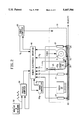
- FIG. 1 is a perspective view of the apparatus useful in practicing this invention.
- FIG. 2 is a schematic of the apparatus of FIG. 1 showing control components associated with the apparatus for controlling the process of this invention.
- FIG. 3 is a block diagram representing a primary and a secondary control loop, for software signal flow inside the process computer.
- FIGS. 1-3 show the relationship of the various components of the apparatus for placement and in-situ consolidation of polymer coated multifilament fiber tows.
- a gas torch 20 i.e., a first heating source
- the mandrel is shown having an out-of-round shape which results in variable velocity for the tow as it is laid down on the mandrel.
- IR heaters 23 preheat the tow 22a
- guide shoe 26 heated by electrically energized cartridge heaters 28 provides additional heat to the tow as it moves to the mandrel to prevent excessive cooldown.
- the guide shoe 26 also presses the tow 22a against the mandrel and smooths it.
- a compaction roller 30 applies force to the incoming layer of tow 22a and cools it to freeze the tow 22a during laydown with layers of polymer coated tow 22, fussing them together.
- a cutter 32 is positioned upstream of heated shoe 26.
- a die 34 guides the tow and aligns it to the correct path.
- the torch 20, the IR heaters 23, the hot guide shoe 26, and the compaction roller 30 are all mounted to a robot tow placement head represented by the box outlined dashed lines 61 encompassing these elements (FIG. 2).
- FIG. 2 schematically shows the physical signal flow among process hardware components.
- a remote electronics interface 40 serves as a common bus for signals to be shared and routed among the various hardware components.
- a torch controller 20a controls gas flow to the torch 20 as well as ignition of the gas flowing from the torch.
- a process computer 50 sends commands to the torch controller 20a and the robot controller 60 via the interface 40.
- the process signals required for the control system of this invention include:
- T 1 a signal generated by a pyrometer 21 representing the surface temperature of the tow substrate 22 as the tow enters beneath the torch 20.
- T 2 a signal generated by a pyrometer 21 representing the surface temperature of the tow 22 substrate laid down on mandrel 24 as the tow substrate exits from beneath the torch 20.
- T 3 a signal generated by a pyrometer 21 representing the surface temperature of the tow 22a as the tow moves beyond the compaction roller 30 on the mandrel 24.
- T 4 a signal representing the surface temperature of the tow 22a as the tow leaves the guide shoe 26.
- T 5 a signal representing the temperature of the guide shoe 26.
- G 2 a signal representing gas flow rate or the amount of gas flowing to the torch as measured within torch controller 20a.
- V 2 a signal representing the instantaneous process laydown velocity as measured by tachometer 31 attached to compaction roller 30.
- V 1 a signal representing maximum velocity achievable by the robot due to kinematic constraints updated continuously by the robot computer 60.
- a keyboard 52 is attached to computer 50 and the following settings are entered by the user or operator to the computer by means of the keyboard:
- T s --temperature set point the desired temperature exiting the torch 20.
- V s --velocity set point the maximum rate of laydown of the tow 22a.
- FIG. 3 shows the software signal flow inside the process computer 50 (e.g. Dell Dx/50M).
- the two control loops 70 and 80 take the user defined setpoints and the process signals and calculate commands for the gas flow and velocity, respectively.
- the first loop 80 manipulates the velocity to maintain the process temperature at the user defined temperature setpoint T s .
- the measured temperature T 2 is subtracted from the temperature setpoint T s to generate a temperature error.
- the temperature error is fed into a modified PTD feedback controller 82 together with the gas flow measurement G 2 to calculate the first component of the velocity command.
- the temperature setpoint T s and the gas flow G 2 measured are fed into a model based feedforward calculation (equation 1) to calculate the second component of the velocity command.
- the first 83 and second 84 components of the velocity command are added together to produce a desired velocity command 85. This desired velocity command is compared with a user set lower limit 86 and the time varying upper limit 87 received from the robot computer 60.
- the upper limit appears in both the first and second loops and is shown separately, though the signal is identical. If the desired velocity command is within limits, the velocity command equals the desired value and is sent out to the robot computer via the remote electronics interface.
- the velocity saturation signal 86 is set to zero. If the desired velocity command is above the upper limit, the velocity command is set to the upper limit, and a velocity saturation signal is calculated as the desired velocity command 85 minus the upper limit. If the desired velocity command is below the lower limit, the velocity command is set to the lower limit, and a velocity saturation signal is calculated as the desired velocity command 85 minus the lower limit.
- the calculated velocity saturation value 86 is sent to the second loop 70, but is not shown directly connected.
- the second loop 70 manipulates gas flow to achieve the desired laydown rate.
- the desired velocity is the minimum of the velocity limit 87 received from the robot computer and the user set velocity setpoint V 2 .
- the velocity measured (V s ) is subtracted from the desired velocity (V 1 ) to generate a velocity error, which is fed into a PID controller 72 to calculate the first component 74 of the gas command.
- the desired velocity and the temperature setpoint are fed into a model based feedforward calculation (equation 1) to calculate the second component of the gas command.
- the velocity saturation 86 from the first loop is fed into a velocity saturation compensation calculation to calculate the third component of the gas command.
- the desired gas command is constrained in 77 to the gas flow permitted by the torch controller i.e. by gas command 78 before being sent out to the torch controller.
- the PID controllers and the model based feedforward calculations were all implemented in software.
- the model based feedforward calculations make use of the heat transfer model described above which relates the gas flow, laydown velocity, and temperature rise. Parameters in the heat transfer were empirically determined on the actual process hardware.
- the PID loop parameters were tuned using software simulations incorporating these empirically determined model parameters.
Abstract
Description
ΔT=KqV.sup.-n
Claims (5)
Priority Applications (1)
| Application Number | Priority Date | Filing Date | Title |
|---|---|---|---|
| US08/273,684 US5447586A (en) | 1994-07-12 | 1994-07-12 | Control of thermoplastic tow placement |
Applications Claiming Priority (1)
| Application Number | Priority Date | Filing Date | Title |
|---|---|---|---|
| US08/273,684 US5447586A (en) | 1994-07-12 | 1994-07-12 | Control of thermoplastic tow placement |
Publications (1)
| Publication Number | Publication Date |
|---|---|
| US5447586A true US5447586A (en) | 1995-09-05 |
Family
ID=23044983
Family Applications (1)
| Application Number | Title | Priority Date | Filing Date |
|---|---|---|---|
| US08/273,684 Expired - Lifetime US5447586A (en) | 1994-07-12 | 1994-07-12 | Control of thermoplastic tow placement |
Country Status (1)
| Country | Link |
|---|---|
| US (1) | US5447586A (en) |
Cited By (37)
| Publication number | Priority date | Publication date | Assignee | Title |
|---|---|---|---|---|
| US5643382A (en) * | 1994-09-15 | 1997-07-01 | Solvay | Process and device for manufacturing a reinforced composite article |
| US5700347A (en) * | 1996-01-11 | 1997-12-23 | The Boeing Company | Thermoplastic multi-tape application head |
| FR2766409A1 (en) * | 1997-07-23 | 1999-01-29 | Dinobat | Machine to produce tubes for lost mould concrete casting |
| FR2784930A1 (en) * | 1998-10-23 | 2000-04-28 | Vetrotex France Sa | Glass reinforced thermoplastic pipe, etc. for handling pressurized fluid has helically wound reinforcement away from wall surfaces and wall with specified maximum vacuum volume proportion |
| US6086696A (en) * | 1998-07-21 | 2000-07-11 | The Boeing Company | Method of forming a seamless, cylindrical, thermoplastic structure with a multiple compaction roller winder |
| US6112792A (en) * | 1998-11-19 | 2000-09-05 | The Boeing Company | Fiber placement mid-span redirect |
| US20030102070A1 (en) * | 2001-11-30 | 2003-06-05 | The Boeing Company | System, method, and computer program product for providing control for high speed fiber placement |
| US20050067731A1 (en) * | 2003-04-17 | 2005-03-31 | Alain Bruyere | Process and system for fabricating a reinforcing preform |
| WO2005108046A1 (en) * | 2004-05-07 | 2005-11-17 | Vetco Aibel As | A method and an apparatus for fabricating an essentially cylindrically shaped object |
| US20060073309A1 (en) * | 2004-10-05 | 2006-04-06 | The Boeing Company | Method for laying composite tape |
| US20060073311A1 (en) * | 2004-10-05 | 2006-04-06 | The Boeing Company | Apparatus and method for composite tape profile cutting |
| US20090229760A1 (en) * | 2005-03-03 | 2009-09-17 | Alexander Hamlyn | Fiber application machine |
| US20100252183A1 (en) * | 2009-04-02 | 2010-10-07 | Olivier Munaux | Method and machine for applying a band of fibers on convex surfaces and/or with edges |
| US20110011537A1 (en) * | 2009-07-17 | 2011-01-20 | Alexander Hamlyn | Fiber application machine comprising a flexible compacting roller with a thermal regulation system |
| US20110011538A1 (en) * | 2009-07-17 | 2011-01-20 | Alexander Hamlyn | Fiber application machine with compacting roller transparent to the radiation of the heating system |
| US20110014429A1 (en) * | 2005-09-07 | 2011-01-20 | The Boeing Company | Composite Member Defining a Contour Surface |
| US20110117231A1 (en) * | 2009-11-19 | 2011-05-19 | General Electric Company | Fiber placement system and method with inline infusion and cooling |
| US20110240213A1 (en) * | 2008-10-02 | 2011-10-06 | Carsten Barlag | Method and device for laying and draping portions of a reinforcing fiber structure to produce a profiled preform |
| US8057618B2 (en) | 2007-02-21 | 2011-11-15 | Coriolis Composites | Method and apparatus for making structures of composite material, in particular airplane fuselage sections |
| US20120073750A1 (en) * | 2009-03-23 | 2012-03-29 | Airbus Operations Gmbh | Pressing apparatus and pressing and depositing system for depositing a sliver on a double-curved surface, and use and method |
| AU2005310286B2 (en) * | 2004-10-19 | 2012-05-17 | Cmd Corporation | Rotary bag machine |
| US8226597B2 (en) | 2002-06-21 | 2012-07-24 | Baxter International, Inc. | Fluid delivery system and flow control therefor |
| US20130000838A1 (en) * | 2011-07-01 | 2013-01-03 | Adc Acquisition Company | Fluid medium non-contact consolidation |
| US20140233176A1 (en) * | 2013-02-20 | 2014-08-21 | Dell Products L.P. | Systems and methods for control of a closed-loop system |
| US20150001214A1 (en) * | 2012-01-11 | 2015-01-01 | Lg Hausys, Ltd. | Hybrid winding method for thermoplastic plastic-continuous fiber hybrid composite and a high pressure vessel using the same and a method for manufacturing the same |
| US20160214752A1 (en) * | 2015-01-22 | 2016-07-28 | Ishida Co., Ltd. | Packaging apparatus |
| US9527237B2 (en) | 2013-01-04 | 2016-12-27 | Orbital Atk, Inc. | Induction heating compaction system |
| US20170021596A1 (en) * | 2015-05-05 | 2017-01-26 | Sunrez Corp. | Fiber Reinforced Core |
| US20190061282A1 (en) * | 2017-08-29 | 2019-02-28 | The Boeing Company | Heater System for Fiber Placement Machine |
| US20190193345A1 (en) * | 2016-09-08 | 2019-06-27 | The Boeing Company | Dynamic heater control for automated fiber placement machines |
| US10369594B2 (en) | 2015-04-01 | 2019-08-06 | Coriolis Group | Fiber application head with a specific application roll |
| US20190383759A1 (en) * | 2018-06-14 | 2019-12-19 | The Boeing Company | Method and apparatus for controlling contact of composite tows |
| US10821682B2 (en) | 2015-10-28 | 2020-11-03 | Coriolis Group | Fiber application machine comprising specific cutting systems |
| US10894341B2 (en) | 2016-03-07 | 2021-01-19 | Coriolis Group | Method for producing preforms with application of a binder to dry fiber, and corresponding machine |
| US11491741B2 (en) | 2016-09-27 | 2022-11-08 | Coriolis Group | Process for producing composite material parts by impregnating a specific preform |
| US11738522B2 (en) | 2015-11-02 | 2023-08-29 | Teijin Carbon America, Inc. | Thermoplastic composite in-situ melt processing method for composite overwrapped tools |
| EP4299295A1 (en) * | 2022-07-01 | 2024-01-03 | Rohr, Inc. | Independently depositing and in situ consolidating thermoplastic material |
Citations (11)
| Publication number | Priority date | Publication date | Assignee | Title |
|---|---|---|---|---|
| US3313670A (en) * | 1963-01-22 | 1967-04-11 | Smith Corp A O | Apparatus for fabricating plastic pipe |
| US4990213A (en) * | 1988-11-29 | 1991-02-05 | Northrop Corporation | Automated tape laminator head for thermoplastic matrix composite material |
| US4992133A (en) * | 1988-09-30 | 1991-02-12 | Pda Engineering | Apparatus for processing composite materials |
| US5039368A (en) * | 1989-09-25 | 1991-08-13 | Thiokol Corporation | Thermoplastic matrix filament winding head |
| EP0463611A2 (en) * | 1990-06-25 | 1992-01-02 | E.I. Du Pont De Nemours And Company | Apparatus and method for winding fiber reinforced thermoplastic resin tow and product thereof |
| US5078592A (en) * | 1990-04-09 | 1992-01-07 | Grimshaw Michael N | Heating system for composite tape |
| EP0491355A1 (en) * | 1990-12-19 | 1992-06-24 | Hercules Incorporated | Fiber placement compaction preheat system |
| US5160568A (en) * | 1987-09-11 | 1992-11-03 | E. I. Du Pont De Nemours And Company | Apparatus including a heated guide eye for winding a plurality of lengths of thermoplastic resin impregnated yarns |
| EP0534092A1 (en) * | 1991-07-31 | 1993-03-31 | Hercules Incorporated | Cure-on-the-fly system |
| US5266139A (en) * | 1992-10-02 | 1993-11-30 | General Dynamics Corporation, Space Systems Division | Continuous processing/in-situ curing of incrementally applied resin matrix composite materials |
| USH1261H (en) * | 1992-05-15 | 1993-12-07 | Gibson Baylor D | On-line consolidation of filament wound thermoplastic parts |
-
1994
- 1994-07-12 US US08/273,684 patent/US5447586A/en not_active Expired - Lifetime
Patent Citations (11)
| Publication number | Priority date | Publication date | Assignee | Title |
|---|---|---|---|---|
| US3313670A (en) * | 1963-01-22 | 1967-04-11 | Smith Corp A O | Apparatus for fabricating plastic pipe |
| US5160568A (en) * | 1987-09-11 | 1992-11-03 | E. I. Du Pont De Nemours And Company | Apparatus including a heated guide eye for winding a plurality of lengths of thermoplastic resin impregnated yarns |
| US4992133A (en) * | 1988-09-30 | 1991-02-12 | Pda Engineering | Apparatus for processing composite materials |
| US4990213A (en) * | 1988-11-29 | 1991-02-05 | Northrop Corporation | Automated tape laminator head for thermoplastic matrix composite material |
| US5039368A (en) * | 1989-09-25 | 1991-08-13 | Thiokol Corporation | Thermoplastic matrix filament winding head |
| US5078592A (en) * | 1990-04-09 | 1992-01-07 | Grimshaw Michael N | Heating system for composite tape |
| EP0463611A2 (en) * | 1990-06-25 | 1992-01-02 | E.I. Du Pont De Nemours And Company | Apparatus and method for winding fiber reinforced thermoplastic resin tow and product thereof |
| EP0491355A1 (en) * | 1990-12-19 | 1992-06-24 | Hercules Incorporated | Fiber placement compaction preheat system |
| EP0534092A1 (en) * | 1991-07-31 | 1993-03-31 | Hercules Incorporated | Cure-on-the-fly system |
| USH1261H (en) * | 1992-05-15 | 1993-12-07 | Gibson Baylor D | On-line consolidation of filament wound thermoplastic parts |
| US5266139A (en) * | 1992-10-02 | 1993-11-30 | General Dynamics Corporation, Space Systems Division | Continuous processing/in-situ curing of incrementally applied resin matrix composite materials |
Cited By (63)
| Publication number | Priority date | Publication date | Assignee | Title |
|---|---|---|---|---|
| US5643382A (en) * | 1994-09-15 | 1997-07-01 | Solvay | Process and device for manufacturing a reinforced composite article |
| US5700347A (en) * | 1996-01-11 | 1997-12-23 | The Boeing Company | Thermoplastic multi-tape application head |
| FR2766409A1 (en) * | 1997-07-23 | 1999-01-29 | Dinobat | Machine to produce tubes for lost mould concrete casting |
| US6086696A (en) * | 1998-07-21 | 2000-07-11 | The Boeing Company | Method of forming a seamless, cylindrical, thermoplastic structure with a multiple compaction roller winder |
| FR2784930A1 (en) * | 1998-10-23 | 2000-04-28 | Vetrotex France Sa | Glass reinforced thermoplastic pipe, etc. for handling pressurized fluid has helically wound reinforcement away from wall surfaces and wall with specified maximum vacuum volume proportion |
| WO2000024566A1 (en) * | 1998-10-23 | 2000-05-04 | Vetrotex France, S.A. | Hollow solid generated by rotation and method for making same |
| US6112792A (en) * | 1998-11-19 | 2000-09-05 | The Boeing Company | Fiber placement mid-span redirect |
| US20030102070A1 (en) * | 2001-11-30 | 2003-06-05 | The Boeing Company | System, method, and computer program product for providing control for high speed fiber placement |
| WO2003047845A1 (en) * | 2001-11-30 | 2003-06-12 | The Boeing Company | System, method, and computer program product for providing control for high speed fiber placement |
| US8672876B2 (en) | 2002-06-21 | 2014-03-18 | Baxter International Inc. | Fluid delivery system and flow control therefor |
| US8231566B2 (en) | 2002-06-21 | 2012-07-31 | Baxter International, Inc. | Fluid delivery system and flow control therefor |
| US8226597B2 (en) | 2002-06-21 | 2012-07-24 | Baxter International, Inc. | Fluid delivery system and flow control therefor |
| US20050067731A1 (en) * | 2003-04-17 | 2005-03-31 | Alain Bruyere | Process and system for fabricating a reinforcing preform |
| US7115180B2 (en) * | 2003-04-17 | 2006-10-03 | Hexcel Reinforcements | Process and system for fabricating a reinforcing preform |
| WO2005108046A1 (en) * | 2004-05-07 | 2005-11-17 | Vetco Aibel As | A method and an apparatus for fabricating an essentially cylindrically shaped object |
| US20060073309A1 (en) * | 2004-10-05 | 2006-04-06 | The Boeing Company | Method for laying composite tape |
| US20060073311A1 (en) * | 2004-10-05 | 2006-04-06 | The Boeing Company | Apparatus and method for composite tape profile cutting |
| US7842145B2 (en) | 2004-10-05 | 2010-11-30 | The Boeing Company | Method for laying composite tape |
| AU2005310286B2 (en) * | 2004-10-19 | 2012-05-17 | Cmd Corporation | Rotary bag machine |
| US20090229760A1 (en) * | 2005-03-03 | 2009-09-17 | Alexander Hamlyn | Fiber application machine |
| US8733417B2 (en) | 2005-03-03 | 2014-05-27 | Coriolis Composites | Fiber application machine |
| US20110014429A1 (en) * | 2005-09-07 | 2011-01-20 | The Boeing Company | Composite Member Defining a Contour Surface |
| US8318291B2 (en) | 2005-09-07 | 2012-11-27 | The Boeing Company | Composite member defining a contour surface |
| US8057618B2 (en) | 2007-02-21 | 2011-11-15 | Coriolis Composites | Method and apparatus for making structures of composite material, in particular airplane fuselage sections |
| US20110240213A1 (en) * | 2008-10-02 | 2011-10-06 | Carsten Barlag | Method and device for laying and draping portions of a reinforcing fiber structure to produce a profiled preform |
| US9399325B2 (en) * | 2008-10-02 | 2016-07-26 | Airbus Operations Gmbh | Method and device for laying and draping portions of a reinforcing fiber structure to produce a profiled preform |
| US8394223B2 (en) * | 2009-03-23 | 2013-03-12 | Airbus Operations Gmbh | Pressing apparatus and pressing and depositing system for depositing a sliver on a double-curved surface, and use and method |
| US20120073750A1 (en) * | 2009-03-23 | 2012-03-29 | Airbus Operations Gmbh | Pressing apparatus and pressing and depositing system for depositing a sliver on a double-curved surface, and use and method |
| US20100252183A1 (en) * | 2009-04-02 | 2010-10-07 | Olivier Munaux | Method and machine for applying a band of fibers on convex surfaces and/or with edges |
| US8052819B2 (en) * | 2009-04-02 | 2011-11-08 | Coriolis Composites | Method and machine for applying a band of fibers on convex surfaces and/or with edges |
| US20110011538A1 (en) * | 2009-07-17 | 2011-01-20 | Alexander Hamlyn | Fiber application machine with compacting roller transparent to the radiation of the heating system |
| US8191596B2 (en) | 2009-07-17 | 2012-06-05 | Coriolis Composites | Fiber application machine comprising a flexible compacting roller with a thermal regulation system |
| US20110011537A1 (en) * | 2009-07-17 | 2011-01-20 | Alexander Hamlyn | Fiber application machine comprising a flexible compacting roller with a thermal regulation system |
| US20110117231A1 (en) * | 2009-11-19 | 2011-05-19 | General Electric Company | Fiber placement system and method with inline infusion and cooling |
| US8911579B2 (en) * | 2011-07-01 | 2014-12-16 | Adc Acquisition Company | Fluid medium non-contact consolidation |
| US20130000838A1 (en) * | 2011-07-01 | 2013-01-03 | Adc Acquisition Company | Fluid medium non-contact consolidation |
| US20150001214A1 (en) * | 2012-01-11 | 2015-01-01 | Lg Hausys, Ltd. | Hybrid winding method for thermoplastic plastic-continuous fiber hybrid composite and a high pressure vessel using the same and a method for manufacturing the same |
| US9527237B2 (en) | 2013-01-04 | 2016-12-27 | Orbital Atk, Inc. | Induction heating compaction system |
| US9519320B2 (en) * | 2013-02-20 | 2016-12-13 | Dell Products L.P. | Systems and methods for control of a closed-loop system |
| US20140233176A1 (en) * | 2013-02-20 | 2014-08-21 | Dell Products L.P. | Systems and methods for control of a closed-loop system |
| US10310573B2 (en) | 2013-02-20 | 2019-06-04 | Dell Products L.P. | Systems and methods for control of a closed-loop system |
| US20160214752A1 (en) * | 2015-01-22 | 2016-07-28 | Ishida Co., Ltd. | Packaging apparatus |
| US10035613B2 (en) * | 2015-01-22 | 2018-07-31 | Ishida Co., Ltd. | Packaging apparatus |
| US10369594B2 (en) | 2015-04-01 | 2019-08-06 | Coriolis Group | Fiber application head with a specific application roll |
| US20170021596A1 (en) * | 2015-05-05 | 2017-01-26 | Sunrez Corp. | Fiber Reinforced Core |
| US10821682B2 (en) | 2015-10-28 | 2020-11-03 | Coriolis Group | Fiber application machine comprising specific cutting systems |
| US11738522B2 (en) | 2015-11-02 | 2023-08-29 | Teijin Carbon America, Inc. | Thermoplastic composite in-situ melt processing method for composite overwrapped tools |
| US10894341B2 (en) | 2016-03-07 | 2021-01-19 | Coriolis Group | Method for producing preforms with application of a binder to dry fiber, and corresponding machine |
| US10974466B2 (en) * | 2016-09-08 | 2021-04-13 | The Boeing Company | Dynamic heater control for automated fiber placement machines |
| CN113085224B (en) * | 2016-09-08 | 2022-09-13 | 波音公司 | Dynamic heater control method and system for an automated fiber placement machine |
| US20190193345A1 (en) * | 2016-09-08 | 2019-06-27 | The Boeing Company | Dynamic heater control for automated fiber placement machines |
| CN113085224A (en) * | 2016-09-08 | 2021-07-09 | 波音公司 | Dynamic heater control method and system for an automated fiber placement machine |
| US11491741B2 (en) | 2016-09-27 | 2022-11-08 | Coriolis Group | Process for producing composite material parts by impregnating a specific preform |
| US20200094494A1 (en) * | 2017-08-29 | 2020-03-26 | The Boeing Company | Heater System for Fiber Placement Machine |
| EP3476577A1 (en) * | 2017-08-29 | 2019-05-01 | The Boeing Company | Heater system for fiber placement machine |
| US10946593B2 (en) * | 2017-08-29 | 2021-03-16 | The Boeing Company | Heater system for fiber placement machine |
| EP3733388A1 (en) * | 2017-08-29 | 2020-11-04 | The Boeing Company | Heater system for fiber placement machine |
| JP2019077170A (en) * | 2017-08-29 | 2019-05-23 | ザ・ボーイング・カンパニーThe Boeing Company | Heater system for fiber arrangement machine |
| US10525638B2 (en) * | 2017-08-29 | 2020-01-07 | The Boeing Company | Heater system for fiber placement machine |
| US20190061282A1 (en) * | 2017-08-29 | 2019-02-28 | The Boeing Company | Heater System for Fiber Placement Machine |
| US10928340B2 (en) * | 2018-06-14 | 2021-02-23 | The Boeing Company | Method and apparatus for controlling contact of composite tows |
| US20190383759A1 (en) * | 2018-06-14 | 2019-12-19 | The Boeing Company | Method and apparatus for controlling contact of composite tows |
| EP4299295A1 (en) * | 2022-07-01 | 2024-01-03 | Rohr, Inc. | Independently depositing and in situ consolidating thermoplastic material |
Similar Documents
| Publication | Publication Date | Title |
|---|---|---|
| US5447586A (en) | Control of thermoplastic tow placement | |
| EP0534092B1 (en) | Cure-on-the-fly system | |
| US6701990B1 (en) | Roll forming machine | |
| EP1820626B1 (en) | System and method for heating carbon fiber using infrared radiation in a fiber placement machine | |
| CN108495729B (en) | Method for the generative production of components by means of a heatable building platform and device for said method | |
| JPH04341830A (en) | Delivery head | |
| EP0846665B1 (en) | Process and apparatus for manufacturing a glass preform for optical fibres by drawing a preform | |
| US11648725B2 (en) | Method and apparatus for heating plastic preforms | |
| WO2009026673A1 (en) | Closed loop control for an injection unit | |
| RU2409525C1 (en) | Method of producing optical fibres and device to this end | |
| JPH04343732A (en) | Device for arranging, compressing and preheating fiber | |
| KR101762667B1 (en) | A filament feeding apparatus for 3D printer | |
| AU2018247568B2 (en) | Apparatus for spray deposition | |
| RU2722944C1 (en) | Three-dimensional printing method with thermoplastic composite material | |
| US4098927A (en) | Method for producing fibre-reinforced thermoplastic polymer | |
| US20220184898A1 (en) | Improvements in and relating to composite manufacturing | |
| CN105603353B (en) | A kind of intelligence fortune control system for sensing pre- hot melt and applying integrating device | |
| US20210197423A1 (en) | Device and method for producing preforms | |
| CN205501396U (en) | Intelligence fortune accuse system of scribbling integrated device that melts is preheated in response | |
| JP3901877B2 (en) | Glass base material stretching apparatus and method | |
| JPH07138861A (en) | Method for producing glass fiber chopped strand mat and device therefor | |
| JP2000176990A (en) | Method for regulating lip clearance of t-die | |
| Heider et al. | The automated tow-placement process: optimization and quality control. | |
| JPH03120320A (en) | Sheet temperature control method for continuous annealing furnace | |
| CA1079586A (en) | Method for producing fibre-reinforced thermoplastic polymer |
Legal Events
| Date | Code | Title | Description |
|---|---|---|---|
| AS | Assignment |
Owner name: E. I. DU PONT DE NEMOURS AND COMPANY, DELAWARE Free format text: ASSIGNMENT OF ASSIGNORS INTEREST;ASSIGNOR:TAM, ALBERT SHEUNG;REEL/FRAME:007117/0678 Effective date: 19940708 |
|
| STCF | Information on status: patent grant |
Free format text: PATENTED CASE |
|
| AS | Assignment |
Owner name: FIBERITE, INC., A DELAWARE CORP., ARIZONA Free format text: ASSIGNMENT OF ASSIGNORS INTEREST;ASSIGNOR:E.I. DU PONT DE NEMOURS AND COMPANY, A DELAWARE CORP.;REEL/FRAME:008621/0594 Effective date: 19970404 Owner name: FIBERITE, INC., A DELAWARE CORPORATION, ARIZONA Free format text: ;ASSIGNOR:E.I. DU PONT DE NEMOURS AND COMPANY;REEL/FRAME:008613/0877 Effective date: 19970404 |
|
| REMI | Maintenance fee reminder mailed | ||
| FPAY | Fee payment |
Year of fee payment: 4 |
|
| SULP | Surcharge for late payment | ||
| FPAY | Fee payment |
Year of fee payment: 8 |
|
| FPAY | Fee payment |
Year of fee payment: 12 |