US5451473A - Long life metal-air (battery and button cells therefor) cell having increased current pulse capability - Google Patents
Long life metal-air (battery and button cells therefor) cell having increased current pulse capability Download PDFInfo
- Publication number
- US5451473A US5451473A US08/162,927 US16292793A US5451473A US 5451473 A US5451473 A US 5451473A US 16292793 A US16292793 A US 16292793A US 5451473 A US5451473 A US 5451473A
- Authority
- US
- United States
- Prior art keywords
- air
- cathode
- metal
- anode
- cell
- Prior art date
- Legal status (The legal status is an assumption and is not a legal conclusion. Google has not performed a legal analysis and makes no representation as to the accuracy of the status listed.)
- Expired - Fee Related
Links
Images


Classifications
-
- H—ELECTRICITY
- H01—ELECTRIC ELEMENTS
- H01M—PROCESSES OR MEANS, e.g. BATTERIES, FOR THE DIRECT CONVERSION OF CHEMICAL ENERGY INTO ELECTRICAL ENERGY
- H01M12/00—Hybrid cells; Manufacture thereof
- H01M12/04—Hybrid cells; Manufacture thereof composed of a half-cell of the fuel-cell type and of a half-cell of the primary-cell type
- H01M12/06—Hybrid cells; Manufacture thereof composed of a half-cell of the fuel-cell type and of a half-cell of the primary-cell type with one metallic and one gaseous electrode
-
- H—ELECTRICITY
- H01—ELECTRIC ELEMENTS
- H01M—PROCESSES OR MEANS, e.g. BATTERIES, FOR THE DIRECT CONVERSION OF CHEMICAL ENERGY INTO ELECTRICAL ENERGY
- H01M50/00—Constructional details or processes of manufacture of the non-active parts of electrochemical cells other than fuel cells, e.g. hybrid cells
- H01M50/20—Mountings; Secondary casings or frames; Racks, modules or packs; Suspension devices; Shock absorbers; Transport or carrying devices; Holders
- H01M50/204—Racks, modules or packs for multiple batteries or multiple cells
- H01M50/207—Racks, modules or packs for multiple batteries or multiple cells characterised by their shape
- H01M50/216—Racks, modules or packs for multiple batteries or multiple cells characterised by their shape adapted for button or coin cells
-
- H—ELECTRICITY
- H01—ELECTRIC ELEMENTS
- H01M—PROCESSES OR MEANS, e.g. BATTERIES, FOR THE DIRECT CONVERSION OF CHEMICAL ENERGY INTO ELECTRICAL ENERGY
- H01M6/00—Primary cells; Manufacture thereof
- H01M6/42—Grouping of primary cells into batteries
- H01M6/44—Grouping of primary cells into batteries of tubular or cup-shaped cells
Definitions
- This invention relates to a long life metal-air cell having increased current pulse capability provided by a novel air reservoir structure disposed therewithin.
- This invention also relates to a novel battery particularly adapted for low current computer back-up power applications, such as to provide back-up power to computer real time clocks and computer configuration retention memories.
- the battery has a plurality of metal-air cells capable of providing adequate voltage at low rate discharge over extended periods of time, but which also provide significantly increased pulse currents relative to metal-air cells of the prior art.
- the first type provides primary power for the entire computer and the second type provides a back-up power source for the real time clock and other functions.
- the back-up power source is required only for the real time clock and configuration memory retention, while in portable computers back-up power is additionally required for microprocessor suspend functions which increase energy drain rates. Consequently, since the increase in energy drain rates on an intermittent basis.
- back-up power sources in portable computers must be capable of providing more power on an intermittent basis than their desktop computer counterparts.
- nickel-cadmium rechargeable batteries might appear to be suitable for providing back-up power in portable computers.
- sporadic use of portable computers often yields insufficient charge time for nickel-cadmium batteries, resulting in an increase incidence of data loss and battery failure.
- nickel-cadmium batteries self discharge at a rate of 1% per day. Thus, such batteries may be totally discharged prior to purchase by the consumer.
- cadmium is considered an environmental hazard rendering the disposal of nickel-cadmium batteries problematic.
- lithium thionyl chloride batteries feature a low voltage, i.e., 3.6 Volts, close to the minimum voltage required to power most integrated circuits (hereinafter "IC" or “lCs”).
- IC integrated circuits
- lithium thionyl chloride cells have been shown to be extremely dangerous in accidental abuse situations. Safer lithium chemistry cells such as lithium manganese dioxide button cells feature even lower voltages of 3.0 Volts or less, thus further limiting IC selection.
- the relatively large size of such cells may cause problems when attempting to design low profile devices.
- metal-air cells i.e., electrochemical cells wherein the oxygen in the air is the cathode material and a metallic material is the anode material.
- the preferred metal is zinc.
- metal-air cells air enters the cell through one or more pods in the cell which are either immediately adjacent to a cathode assembly, or separated from the cathode assembly by an air chamber. In either arrangement, the air diffuses into the cathode assembly where the oxygen in the air reacts with the water in the electrolyte consuming electrons and producing hydroxide ions. These ions then oxidize the metallic anode material producing one or more electrons for each atom of metal reacted.
- air cathode electrochemical cells are well known, and are more fully discussed in U.S. Pat. No. 4,591,539 (Oltman et al.).
- metal-air cells am environmentally benign.
- the cathode assembly also decreases the rate of diffusion of other gases into and out of the cell, particularly water vapor.
- the rate of oxygen ingress into the cathode to react with water and thereby produce hydroxide ions is the limiting factor to the rate of discharge of the cell.
- the moisture content inside the cell is balanced with the metal (e.g., zinc) content, for the most efficient use of this anode material. The gain or loss of too much moisture can reduce discharge efficiency.
- some metal-air cells include a restrictive membrane between the exterior of the cell and the cathode layer.
- the restrictive membrane is usually located immediately adjacent to the cathode assembly.
- the restrictive membrane is located between the air chamber and the air cathode assembly. Regardless of whether the cells provide an air chamber, the restrictive membrane limits moisture transport into and out of the cell. As noted above, the moisture content of the cell interior is one of the factors influencing cell efficiency.
- a restrictive membrane limits not only the flow of moisture into and out of the cell, but also the flow of oxygen into the cell. Because oxygen is the cathodic material in metal-air cells, a reduction in oxygen ingress rate limits the rate capability of such cells. Because portable computers may require that the backup power source provide a pulse capability, prior art low rate metal-air cells have not been preferred for such applications.
- Another object of the present invention is to provide a long-life battery having increased pulse capability.
- Still another object of the present invention is to provide a long-life battery which produces a voltage greater than the IC effective minimum of three volts, yet has a significant pulse capability.
- Yet another object of the present invention is to provide for a long-life battery that occupies a minimum amount of space.
- Another object of the present invention is to provide a metal-air cell which controls air ingress such that the cell can provide pulse currents.
- Still another object of the present invention is to provide metal-air cells which are substantially unaffected by changes in the ambient relative humidity.
- the present invention provides for a battery which is particularly adapted for use as a back-up power source for portable computers.
- a battery can provide a back-up power source for real time clocks, configuration files and microprocessor suspend functions.
- the battery comprises a plurality of novel metal-air button cells, each of which utilizes a restrictive membrane that permits oxygen to enter the cell at a rate greater than the minimum necessary to provide the current supplied by the cell during non-pulse use.
- the cells incorporated into the batteries of present invention utilize an air chamber provided on the interior side of the restrictive membrane.
- the restrictive membranes of the metal-air cells of the present invention are located between the cathode can and the air chamber, instead of between the air chamber and the air cathode assembly. That is, the restrictive membrane of the present invention forms the floor of the air chamber, instead of the ceiling.
- the air chamber fills with the air that enters the cell during non-pulse periods beyond the amount needed to supply the non-pulse current.
- the reservoir can provide cathodic material (oxygen) at a much greater rate than the ingress rate through the restrictive membrane. Because the oxygen ingress rate through the restrictive membrane is greater than the minimum necessary to supply the non-pulse current, the reservoir can be replenished with air after a pulse.
- the battery comprises three of the novel metal-air cells arranged in series.
- the housing of the battery is formed so as to allow sufficient air ingress to the metal air cells.
- FIG. 1 is a cross-sectional view of one embodiment of a metal-air cell of the present invention, wherein an air reservoir is formed by the inclusion of a washer-shaped spacer.
- FIG. 2 is a cross-sectional view of another embodiment of a metal-air cell of the present invention, wherein an air reservoir is formed by the inclusion of a porous material.
- FIG. 3 shows changes in cell voltage of cells of the present invention on heavy loads as a function of the duration of the pulse.
- FIG. 4 shows the change in cell capacity over time of cells of the present invention as a function of selected relative humidity storage conditions.
- FIG. 5 shows a perspective view of a battery comprising a plurality of metal-air cells of the present invention.
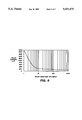
- FIG. 6 shows the output pulse currents a battery of the present invention provides over different pulse durations when placed under a potentiostatic load of 3.9 Volts.
- a metal air cell of the present invention is shown in FIG. 1, and comprises a cathode can 1 having air entry ports 2, and diffusion grid 3 embossed on the interior surface of the bottom of the cathode can 1.
- a restrictive membrane 4 preferably formed of a layer of polytetrafluoroethylene (PTFE or Teflon®) approximately 0.0005 inches thick, is disposed on the floor of the cathode can, and is effectively supported thereby.
- the novel metal-air cell further provides an air reservoir 5 formed by a washer-shaped spacer 6.
- the spacer preferably about 0.005 inches thick, has an outer diameter approximately equal to the inner diameter of the cathode can.
- the spacer is disposed on top of the restrictive membrane, and fits securely inside the cathode can.
- such an air reservoir has an effective volume of approximately 35 microliters.
- An air cathode 7 having a diameter equal to the outer diameter of the spacer is disposed above the spacer and has top and bottom major opposing surfaces.
- a seal ring 8 with an outer diameter approximately equalling to that of the spacer is disposed above the air cathode.
- FIG. 2 shows another embodiment of the novel metal-air cells incorporated into the present invention in which the air reservoir 5 is formed, instead of by the spacer 6, by providing a porous material 12 between the air cathode 7 and the restrictive membrane 4.
- the effective height of this reservoir is approximately 0.012 inches.
- the porous material is an unsintered polytetrafluoroethylene/fluoroethylene propylene (FEP) material.
- FIG. 3 shows the results of those tests, where the functional voltage end point is 1.0 Volts.
- FIG. 3 shows that metal air cells of the present invention can deliver sufficient current to maintain a steady-state load of about 100 ⁇ A.
- the pulse capability for 30 seconds is two decades greater.
- FIG. 4 shows moisture change versus time in a zinc air cell of the present invention for several relative humidities at 70° F.
- all but the heavy "20% RH” line represent theoretical data for the various indicated relative humidity conditions, where the data were calculated on the basis of the known relative humidities of the tested cell and the environment. Since relative humidity changes within the cell were not taken into consideration in the calculations corresponding to the theoretical model, the data in FIG. 4 are conservative. (Note that the heavy line in FIG. 4 labeled "20% RH" represent actual data obtained using metal-air cells of the present invention stored at 20% relative humidity for two years.)
- FIG. 5 shows a perspective view of a battery of the present invention comprising a plurality of the metal-air cells of the present invention connected in series.
- the battery is particularly well adapted for low-current back-up power applications in computers, such as for providing back-up power to real time clocks and to configuration computer memory. Because of its small size, the battery is especially well adapted for use in portable computers such as laptop and notebook computers. Typically, back-up batteries for portable computers require a maximum continuous current capability of 75 ⁇ A, which the battery of the present invention can provide.
- a battery of the present invention may comprise three metal-air cells 21 constructed as described above, and electrically connected in series by nickel strips 27 and 28.
- Terminals 33 and 35 are connected to the positive and negative terminals, respectively, of the first and third metal-air cells connected in series.
- Lead 29 comprises two wires connected to terminals 33 and 35, and is connected to industry standard 4-pin polarized connector 31.
- Insulating adhesive-backed polypropylene rings 37 are placed on the upper surfaces of cells 21 to prevent electrical shorting between the battery terminals and nickel strips 27 and 28.
- Metal-air cells of the present invention are placed in battery housing 22, where barrier walls 47 maintain cells 21 separate from one another within battery housing 22. Between the bottoms of cells 21 and battery housing 22 are disposed air diffusion pads 39 for absorbing electrolyte that may leak from cells 21. Air diffusion pads 39 also provide a pathway for air to the air ingress ports of cells 21, and may be composed of paper. Lead 29 is positioned through battery housing air ingress pod 45 once cells 21 are placed in the housing, thereby permitting battery housing cover 43 to be placed atop battery housing 22, and welded thereon by ultrasonic means. Battery housing air ingress pods 45 and 49 provide pathways for air to enter battery housing 22 to provide oxygen to metal-air cells 21 disposed therein.
- Mounting strip 30 may be attached to the underside of battery housing 22 by adhesive means disposed on its upper surface 57.
- Fibrous VELCRO® backing is disposed on the bottom surface of the mounting strip 30, and is adapted to engage and secure to VELCRO® backing strip 50 having hook-shaped plastic strands on its upper surface 53.
- VELCRO® backing strip 50 may, in turn, be attached by adhesive means disposed on its bottom surface 51 to a surface in the desired location.
- Table 1and FIG. 6 show that as time increases the current delivered by the battery decreases gradually until it asymmtotically approaches a value of about 50 ⁇ A. Fifty ⁇ A represents the amount of current the tested battery would have provided had the air reservoir of the present invention not been present in the cells of the battery.
- Table 1 and FIG. 6 show that the battery of the present invention provides more than 50 ⁇ A of output current over the entire duration of the eighteen-hour test, and that the battery can provide more than 100 ⁇ A of output current for almost an hour. Additionally, FIG. 6 and Table 1 show that the battery can provide 2000 ⁇ A of output current over a one-second interval, and 10,000 ⁇ A on an instantaneous basis.
- a metal-air battery having the air reservoir of the present invention can provide up to forty times more current on an instantaneous, intermittent basis, and up to twice as much current continuously over an hour's time, when compared to prior ad metal-air cells not having the air reservoir of the present invention.
Abstract
Description
              TABLE 1
______________________________________
Output Current vs. Time for a Battery Subjected
to a 3.9 Volt Potentiostatic Discharge Load
Time (sec.)
           Time (min.)
                      Time (hrs.)
                                Current (μA)
______________________________________
0          0.0        0.0000    10000
1          0.02       0.0000    2000
2          0.03       0.0000    989
3          0.05       0.0000    820
4          0.07       0.0000    640
5          0.08       0.0000    500
6          0.10       0.0000    381
7          0.12       0.0000    337
8          0.13       0.0000    302
9          0.15       0.0000    287
10         0.17       0.0000    268
11         0.18       0.0000    248
12         0.20       0.0000    230
13         0.22       0.0000    212
14         0.23       0.0000    196
15         0.25       0.0000    180
3600       60.0       0.0000     92
10800      180.0      0.0000     75
64800      1080       0.0000     61
______________________________________
Claims (24)
Priority Applications (1)
| Application Number | Priority Date | Filing Date | Title |
|---|---|---|---|
| US08/162,927 US5451473A (en) | 1992-01-28 | 1993-12-08 | Long life metal-air (battery and button cells therefor) cell having increased current pulse capability |
Applications Claiming Priority (2)
| Application Number | Priority Date | Filing Date | Title |
|---|---|---|---|
| US82673692A | 1992-01-28 | 1992-01-28 | |
| US08/162,927 US5451473A (en) | 1992-01-28 | 1993-12-08 | Long life metal-air (battery and button cells therefor) cell having increased current pulse capability |
Related Parent Applications (1)
| Application Number | Title | Priority Date | Filing Date |
|---|---|---|---|
| US82673692A Continuation-In-Part | 1992-01-28 | 1992-01-28 |
Publications (1)
| Publication Number | Publication Date |
|---|---|
| US5451473A true US5451473A (en) | 1995-09-19 |
Family
ID=25247400
Family Applications (1)
| Application Number | Title | Priority Date | Filing Date |
|---|---|---|---|
| US08/162,927 Expired - Fee Related US5451473A (en) | 1992-01-28 | 1993-12-08 | Long life metal-air (battery and button cells therefor) cell having increased current pulse capability |
Country Status (1)
| Country | Link |
|---|---|
| US (1) | US5451473A (en) |
Cited By (19)
| Publication number | Priority date | Publication date | Assignee | Title |
|---|---|---|---|---|
| EP0741429A2 (en) * | 1995-05-05 | 1996-11-06 | Rayovac Corporation | Metal-air cathode can and electrochemical cell made therewith |
| EP0771044A2 (en) * | 1995-09-19 | 1997-05-02 | Rayovac Corporation | Metal air cathode can, and electrochemical cell made therewith |
| US5733677A (en) * | 1997-05-19 | 1998-03-31 | Aer Energy Resources, Inc. | Metal-air electrochemical cell with oxygen reservoir |
| US6040074A (en) * | 1995-05-05 | 2000-03-21 | Rayovac Corporation | Metal-air cathode can, and electrochemical cell made therewith |
| US6042704A (en) * | 1995-10-06 | 2000-03-28 | Ceramatec, Inc. | Storage-stable, fluid dispensing device using a hydrogen gas generator |
| US6060196A (en) * | 1995-10-06 | 2000-05-09 | Ceramtec, Inc. | Storage-stable zinc anode based electrochemical cell |
| US6091230A (en) * | 1998-09-18 | 2000-07-18 | Timex Corporation | Voltage recovery method for a zinc-air battery |
| US6197445B1 (en) | 1998-03-06 | 2001-03-06 | Rayovac Corporation | Air depolarized electrochemical cells |
| US6248463B1 (en) | 1997-05-05 | 2001-06-19 | Rayovac Corporation | Metal-air cathode can and electrochemical cell made therewith |
| US6265094B1 (en) | 1998-11-12 | 2001-07-24 | Aer Energy Resources, Inc. | Anode can for a metal-air cell |
| US20020110715A1 (en) * | 1998-10-23 | 2002-08-15 | Schulman Joseph H. | Zinc air battery and its uses |
| US6558828B1 (en) | 2000-05-26 | 2003-05-06 | Eveready Battery Company, Inc. | Zn/air cell performance in extreme humidity by controlling hydrophobic layer porosity |
| EP1498977A1 (en) * | 2002-04-17 | 2005-01-19 | Matsushita Electric Industrial Co., Ltd. | Alkaline storage battery |
| EP1845570A1 (en) * | 2006-03-21 | 2007-10-17 | LG Chemical, Ltd. | Battery module having attachment members between battery cells |
| US20080075995A1 (en) * | 2006-09-22 | 2008-03-27 | Eveready Battery Company, Inc. | Battery having air electrode and biased lever gasket |
| US20080096074A1 (en) * | 2006-10-23 | 2008-04-24 | Eveready Battery Company, Inc. | Electrochemical air cell batteries with air flow channels |
| DE102013203438A1 (en) * | 2013-02-28 | 2014-08-28 | Robert Bosch Gmbh | Galvanic element |
| US10297871B2 (en) * | 2012-03-09 | 2019-05-21 | Nissan Motor Co., Ltd. | Air cell cartridge and air cell system |
| US11641044B1 (en) | 2020-04-14 | 2023-05-02 | Energizer Brands, Llc | Battery housing and systems and methods of making thereof |
Citations (4)
| Publication number | Priority date | Publication date | Assignee | Title |
|---|---|---|---|---|
| US4054726A (en) * | 1975-08-07 | 1977-10-18 | Varta Batterie Aktiengesellschaft | Galvanic primary element with air electrode |
| US4262062A (en) * | 1980-03-24 | 1981-04-14 | Timex Corporation | Metal-air battery with environment control for intermittent high current demand |
| US4620111A (en) * | 1984-06-25 | 1986-10-28 | Duracell Inc. | Auxiliary portable power supply |
| US4640874A (en) * | 1985-07-29 | 1987-02-03 | Duracell Inc. | Metal/air cell |
-
1993
- 1993-12-08 US US08/162,927 patent/US5451473A/en not_active Expired - Fee Related
Patent Citations (4)
| Publication number | Priority date | Publication date | Assignee | Title |
|---|---|---|---|---|
| US4054726A (en) * | 1975-08-07 | 1977-10-18 | Varta Batterie Aktiengesellschaft | Galvanic primary element with air electrode |
| US4262062A (en) * | 1980-03-24 | 1981-04-14 | Timex Corporation | Metal-air battery with environment control for intermittent high current demand |
| US4620111A (en) * | 1984-06-25 | 1986-10-28 | Duracell Inc. | Auxiliary portable power supply |
| US4640874A (en) * | 1985-07-29 | 1987-02-03 | Duracell Inc. | Metal/air cell |
Cited By (34)
| Publication number | Priority date | Publication date | Assignee | Title |
|---|---|---|---|---|
| EP0741429A2 (en) * | 1995-05-05 | 1996-11-06 | Rayovac Corporation | Metal-air cathode can and electrochemical cell made therewith |
| EP0741429A3 (en) * | 1995-05-05 | 1997-05-28 | Ray O Vac Corp | Metal-air cathode can and electrochemical cell made therewith |
| US5733676A (en) * | 1995-05-05 | 1998-03-31 | Rayovac Corporation | Metal-air cathode can and electrochemical cell made therewith |
| US6284400B1 (en) | 1995-05-05 | 2001-09-04 | Rayovac Corporation | Metal-air cathode can, and electrochemical cell made therewith |
| US5904998A (en) * | 1995-05-05 | 1999-05-18 | Rayovac Corporation | Metal-air cathode can and electrochemical cell made therewith |
| US6040074A (en) * | 1995-05-05 | 2000-03-21 | Rayovac Corporation | Metal-air cathode can, and electrochemical cell made therewith |
| EP0771044A2 (en) * | 1995-09-19 | 1997-05-02 | Rayovac Corporation | Metal air cathode can, and electrochemical cell made therewith |
| EP0771044A3 (en) * | 1995-09-19 | 1998-04-01 | Rayovac Corporation | Metal air cathode can, and electrochemical cell made therewith |
| US6042704A (en) * | 1995-10-06 | 2000-03-28 | Ceramatec, Inc. | Storage-stable, fluid dispensing device using a hydrogen gas generator |
| US6060196A (en) * | 1995-10-06 | 2000-05-09 | Ceramtec, Inc. | Storage-stable zinc anode based electrochemical cell |
| US6248463B1 (en) | 1997-05-05 | 2001-06-19 | Rayovac Corporation | Metal-air cathode can and electrochemical cell made therewith |
| US5733677A (en) * | 1997-05-19 | 1998-03-31 | Aer Energy Resources, Inc. | Metal-air electrochemical cell with oxygen reservoir |
| US6197445B1 (en) | 1998-03-06 | 2001-03-06 | Rayovac Corporation | Air depolarized electrochemical cells |
| US6203940B1 (en) | 1998-03-06 | 2001-03-20 | Rayovac Corporation | Tubular air depolarized cell |
| US6210826B1 (en) | 1998-03-06 | 2001-04-03 | Rayovac Corporation | Seals, and electrochemical cells made therewith |
| US6210827B1 (en) | 1998-03-06 | 2001-04-03 | Rayovac Corporation | Elongate air depolarized electrochemical cells |
| US6436571B1 (en) | 1998-03-06 | 2002-08-20 | Rayovac Corporation | Bottom seals in air depolarized electrochemical cells |
| US6296961B1 (en) | 1998-03-06 | 2001-10-02 | Rayovac Corporation | Composite carbon sheet, and electrochemical cells made therewith |
| US6461761B1 (en) | 1998-03-06 | 2002-10-08 | Rayovac Corporation | Air depolarized electrochemical cells |
| US6091230A (en) * | 1998-09-18 | 2000-07-18 | Timex Corporation | Voltage recovery method for a zinc-air battery |
| US6879855B2 (en) | 1998-10-23 | 2005-04-12 | The Alfred E. Mann Foundation For Scientific Research | Zinc air battery and its uses |
| US20020110715A1 (en) * | 1998-10-23 | 2002-08-15 | Schulman Joseph H. | Zinc air battery and its uses |
| US6265094B1 (en) | 1998-11-12 | 2001-07-24 | Aer Energy Resources, Inc. | Anode can for a metal-air cell |
| US6558828B1 (en) | 2000-05-26 | 2003-05-06 | Eveready Battery Company, Inc. | Zn/air cell performance in extreme humidity by controlling hydrophobic layer porosity |
| EP1498977A4 (en) * | 2002-04-17 | 2009-11-25 | Panasonic Corp | Alkaline storage battery |
| EP1498977A1 (en) * | 2002-04-17 | 2005-01-19 | Matsushita Electric Industrial Co., Ltd. | Alkaline storage battery |
| US20050147876A1 (en) * | 2002-04-17 | 2005-07-07 | Yoichi Izumi | Alkaline storage battery |
| EP1845570A1 (en) * | 2006-03-21 | 2007-10-17 | LG Chemical, Ltd. | Battery module having attachment members between battery cells |
| US20080075995A1 (en) * | 2006-09-22 | 2008-03-27 | Eveready Battery Company, Inc. | Battery having air electrode and biased lever gasket |
| US7816026B2 (en) | 2006-09-22 | 2010-10-19 | Eveready Battery Company, Inc. | Battery having air electrode and biased lever gasket |
| US20080096074A1 (en) * | 2006-10-23 | 2008-04-24 | Eveready Battery Company, Inc. | Electrochemical air cell batteries with air flow channels |
| US10297871B2 (en) * | 2012-03-09 | 2019-05-21 | Nissan Motor Co., Ltd. | Air cell cartridge and air cell system |
| DE102013203438A1 (en) * | 2013-02-28 | 2014-08-28 | Robert Bosch Gmbh | Galvanic element |
| US11641044B1 (en) | 2020-04-14 | 2023-05-02 | Energizer Brands, Llc | Battery housing and systems and methods of making thereof |
Similar Documents
| Publication | Publication Date | Title |
|---|---|---|
| US5451473A (en) | Long life metal-air (battery and button cells therefor) cell having increased current pulse capability | |
| CA1062328A (en) | Primary cell with compressible body in anode | |
| US7169497B2 (en) | Electrochemical cells | |
| CA2241012C (en) | Flexible thin layer open electrochemical cell | |
| US6855441B1 (en) | Functionally improved battery and method of making same | |
| CN100472870C (en) | Activating method of fuel cell | |
| US4687714A (en) | Case for metal/air electrochemical cells, and cells and lantern batteries thereof | |
| US20050118464A1 (en) | Functionally improved battery and method of making same | |
| US8088506B2 (en) | Fluid consuming battery with fluid regulating system | |
| US8309260B2 (en) | Oxygen-consuming battery with improved high rate capability | |
| CA2157930C (en) | Sealed rechargeable battery | |
| US5716726A (en) | Electrolyte starved metal-air battery | |
| US5225291A (en) | Deferred actuated battery assembly | |
| EP0230039A2 (en) | Seal tab for a metal-air electrochemical cell | |
| WO2000054360A2 (en) | Air-assisted electrochemical cell construction | |
| US5652073A (en) | Bipolar cell design for a gas depolarized battery | |
| US2812377A (en) | Flat dry cell | |
| US3293078A (en) | Sea water battery and a louvered anode for use therein | |
| US3592695A (en) | Metal-air cell including a composite laminar gas diffusion cathode | |
| US3425874A (en) | Rotatable hydrophobic electrode and fuel cell therewith | |
| US7807304B2 (en) | Zinc air battery | |
| US3589945A (en) | Stacked metal gas-cells | |
| US3522096A (en) | Long life fuel cell and electrode therefor | |
| CN109698388B (en) | Multi-cathode-plate battery | |
| JPS6210872A (en) | Fuel concentration sensor for liquid fuel cell |
Legal Events
| Date | Code | Title | Description |
|---|---|---|---|
| FPAY | Fee payment |
Year of fee payment: 4 |
|
| FPAY | Fee payment |
Year of fee payment: 8 |
|
| REMI | Maintenance fee reminder mailed | ||
| AS | Assignment |
Owner name: GOLDMAN SACHS CREDIT PARTNERS L.P., AS COLLATERAL Free format text: SECURITY AGREEMENT;ASSIGNORS:AQUARIA, INC.;AQUARIUM SYSTEMS, INC.;UNITED PET GROUP, INC.;AND OTHERS;REEL/FRAME:019477/0974 Effective date: 20070330 |
|
| LAPS | Lapse for failure to pay maintenance fees | ||
| STCH | Information on status: patent discontinuation |
Free format text: PATENT EXPIRED DUE TO NONPAYMENT OF MAINTENANCE FEES UNDER 37 CFR 1.362 |
|
| FP | Lapsed due to failure to pay maintenance fee |
Effective date: 20070919 |
|
| AS | Assignment |
Owner name: THE BANK OF NEW YORK MELLON, AS COLLATERAL AGENT, Free format text: ASSIGNMENT OF ASSIGNORS INTEREST;ASSIGNOR:GOLDMAN SACHS CREDIT PARTNERS L.P.;REEL/FRAME:022951/0236 Effective date: 20090520 Owner name: THE BANK OF NEW YORK MELLON, AS COLLATERAL AGENT,T Free format text: ASSIGNMENT OF ASSIGNORS INTEREST;ASSIGNOR:GOLDMAN SACHS CREDIT PARTNERS L.P.;REEL/FRAME:022951/0236 Effective date: 20090520 |