US5451765A - Eye safety protection system for a laser transmission system wherein laser energy scattered back along the beam path is detected - Google Patents
Eye safety protection system for a laser transmission system wherein laser energy scattered back along the beam path is detected Download PDFInfo
- Publication number
- US5451765A US5451765A US08/331,973 US33197394A US5451765A US 5451765 A US5451765 A US 5451765A US 33197394 A US33197394 A US 33197394A US 5451765 A US5451765 A US 5451765A
- Authority
- US
- United States
- Prior art keywords
- laser
- laser beam
- transmission unit
- housing
- laser transmission
- Prior art date
- Legal status (The legal status is an assumption and is not a legal conclusion. Google has not performed a legal analysis and makes no representation as to the accuracy of the status listed.)
- Expired - Fee Related
Links
- 230000005540 biological transmission Effects 0.000 title claims description 25
- 230000003287 optical effect Effects 0.000 claims abstract description 38
- 239000011521 glass Substances 0.000 claims description 2
- 238000010586 diagram Methods 0.000 description 2
- 230000000903 blocking effect Effects 0.000 description 1
- 238000000576 coating method Methods 0.000 description 1
- 238000010276 construction Methods 0.000 description 1
- 230000035945 sensitivity Effects 0.000 description 1
Images


Classifications
-
- B—PERFORMING OPERATIONS; TRANSPORTING
- B23—MACHINE TOOLS; METAL-WORKING NOT OTHERWISE PROVIDED FOR
- B23K—SOLDERING OR UNSOLDERING; WELDING; CLADDING OR PLATING BY SOLDERING OR WELDING; CUTTING BY APPLYING HEAT LOCALLY, e.g. FLAME CUTTING; WORKING BY LASER BEAM
- B23K26/00—Working by laser beam, e.g. welding, cutting or boring
- B23K26/02—Positioning or observing the workpiece, e.g. with respect to the point of impact; Aligning, aiming or focusing the laser beam
- B23K26/03—Observing, e.g. monitoring, the workpiece
- B23K26/032—Observing, e.g. monitoring, the workpiece using optical means
-
- B—PERFORMING OPERATIONS; TRANSPORTING
- B23—MACHINE TOOLS; METAL-WORKING NOT OTHERWISE PROVIDED FOR
- B23K—SOLDERING OR UNSOLDERING; WELDING; CLADDING OR PLATING BY SOLDERING OR WELDING; CUTTING BY APPLYING HEAT LOCALLY, e.g. FLAME CUTTING; WORKING BY LASER BEAM
- B23K26/00—Working by laser beam, e.g. welding, cutting or boring
- B23K26/02—Positioning or observing the workpiece, e.g. with respect to the point of impact; Aligning, aiming or focusing the laser beam
- B23K26/06—Shaping the laser beam, e.g. by masks or multi-focusing
- B23K26/064—Shaping the laser beam, e.g. by masks or multi-focusing by means of optical elements, e.g. lenses, mirrors or prisms
- B23K26/0643—Shaping the laser beam, e.g. by masks or multi-focusing by means of optical elements, e.g. lenses, mirrors or prisms comprising mirrors
Definitions
- This invention relates to protection systems for light responsive systems, and more particularly to a means for controlling the power emitted by a laser in order to insure eye safety.
- the prior art has various shut-off protection systems for light responsive systems.
- One example may be found in U.S. Pat. No. 4,876,444 to B. F. Field which discloses a photodetector mounted on the laser transmission unit of a light guided vehicle. When a certain type light strikes the photodetector, the photodetector emits an electrical signal. This signal is used to override the laser control causing the vehicle to shut down.
- Another example may be found in U.S. Pat. No. 4,960,988 to R. A. Simms which discloses a safety shut-off protection system for light responsive systems.
- the light responsive system includes several, series-connected, normally-closed, light responsive photoelectric Darlington safety switches. These safety switches are located to receive light along with the light responsive systems.
- the present invention provides an improved eye safety protection system for laser systems.
- the general purpose of the present invention which will be described subsequently in greater detail, is to provide a system to control the power emitted by a laser in order to insure eye safety.
- a photodetector is used to measure the light scattered or reflected back along the emitting axis from a beam splitter. This device has sufficient sensitivity to insure that the laser will turn off (or be switched to Laser Class 1--completely eye safe) when any object, including a human eye, is in the path of the laser.
- the present invention measures light returned along the optical axis itself.
- a beam splitter is used and installed in the optical axis. Because a beam splitter is used, it is possible to measure the light along the axis of the component itself. Since a beam splitter is used in the invention, outgoing power may also be measured. This is an important feature for current controlled diode lasers in terms of eye safety.
- a built-in monitor photodiode is provided which gives a precise measure of the optical power emitted by the laser. This measured optical power is used in a feedback circuit and allows for automatic power compensation, that is, the laser is driven so that the desired power is emitted. This ensures that the extra amount of power is emitted by the laser and ensures that the designated laser class specifications are never exceeded.
- CW continuous wave
- pulsed lasers can be insured to fall in the proper laser class at all times.
- the instant invention is different from the above-named patented prior devices in three principal ways. Simms explicitly uses the system to protect light-sensitive components (cameras, imagers, etc) from overexposure by external light sources, whereas the present system is controlling a light-producing component (laser, light emitting diode, etc.) in order to protect illuminated objects (specifically, the human eye and body). Both prior art devices explicitly turn off the light responsive system, whereas the instant invention can be used to not only turn off the component, but to rather switch the laser from a high laser Class to Class 1. Both prior art devices clearly claim cases where light is measured by photodetectors located along side or at a separate location from the optical axis of the light-sensitive component. The instant invention measures light returned along the optical axis itself. A beam splitter is used and the projected axis is coincident with the optical axis of the laser, itself.
- a beam splitter is used and the projected axis is coincident with the optical axis of the laser, itself.
- the instant invention laser and photodetector share a housing and aperture, so that anything which blocks the photodetector path necessarily also blocks the outgoing laser. Retroreflection which would go undetected by prior art devices would be detected by the instant invention. As stated above, outgoing power can be measured as well as incoming light.
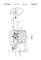
- FIG. 1 is a cross-sectional view showing the general construction of a laser emitting device with the instant invention eye safety protection system.
- FIG. 2 is a block diagram showing an example of the invention.
- FIG. 3 is a partial block diagram showing an alternate example of the invention.
- a laser beam 20 is emitted by and from a laser transmission unit 20 located within a generally rectangular housing 10.
- the housing 10 in this embodiment is rectangular, the housing 10 may have any desired shape.
- the housing 10 has a top 11, bottom 12, a forward end 13 and a rear end 14.
- the top 11 and bottom 12 will be considered in horizontal planes and the forward and rear ends 13, 14 in vertical planes.
- the forward end 13 has an upper opening 15 with an optical element 16 covering the opening 15.
- the optical element 16 is made from planed glass.
- the housing rear end 14 is enclosed.
- the laser transmission unit 20 is located centrally in an upper interior portion 17.
- the laser transmission unit 20 has a generally cylindrical shape and a longitudinal axis parallel with the housing top 11.
- the central longitudinal axis of the laser transmission unit 20 protrudes through the optical element 16 in the front housing opening 15 forming an optical path for projection of a laser beam 21 from the laser transmission unit 20.
- the central, longitudinal axis of the laser transmission unit 20 extending through the housing forward end opening 15 is defined as the laser beam optical axis 31.
- a CW laser transmission unit is used, having a basic frequency band width in the infrared or visible light range.
- a pulsed laser transmission unit may be used.
- a beam splitter 30 is positioned between the laser transmission unit 20 and the housing forward end opening 15 in the optical axis path 31.
- the beam splitter can be an optic with a hole or a short flat surface.
- the beam splitter 30 in this embodiment of the invention is comprised of a mirror 32 positioned at a 45 degree angle to the optical path 31. However, the mirror 32 may be positioned at any other desired angle.
- the mirror 32 has an inner surface 33 and an outer surface 34.
- the inner surface 33 is defined as that surface generally facing the laser transmission unit 20.
- the outer surface 34 is defined as that surface generally facing the housing forward end opening 15.
- the mirror 32 is designed to reflect a certain amount of the energy incident on it and to be transparent to the remaining the energy incident to it.
- the desired amount of energy reflected may be anywhere from 1 to 99% of the energy incident to it.
- the reflected-transparent ratio of the invention 1 may be changed depending upon which side 33, 34 of the mirror 32 is receiving the energy. This may be done with various optical coatings and/or angles (wave lengths) to determine the incident light reflected-transparent ratio.
- the laser beam optical axis 31 passes through the central portion 35 of the mirror 32.
- the laser beam 21 generated by the laser transmission unit 20 proceeds along the optical path 31 through the mirror central portion 35, through the housing front optical element 16 to an object 2.
- Upon striking the object 2 a certain amount of the energy from the laser beam 21 is scattered.
- the scattered energy 22 bounces off the object 2 in every direction.
- the scattered energy 22 is reflected back, i.e., reflected energy 23, along the laser beam optical axis 31 toward the laser transmission unit 20 within the housing 10.
- the reflected energy 23 strikes the mirror outer surface 34 and is directed along a beam-splitted reflected optical path 36 to a detector 40.
- the beam-splitted reflected optical path 36 is at right angles to the laser beam optical axis 31.
- the reflected energy 23 is reflected from the beam splitter mirror outer surface 34 to a detector 40 located directly below the beam splitter 30 within the housing 10.
- the detector 40 is a photoelectric device which converts the reflected laser beam energy 23 from the beam splitter 30 to a voltage output.
- the detector voltage output is passed to an amplifier and filter unit 41 for treatment.
- the treated reflected energy voltage is outputted from the amplifier and filter unit 41 and fed to a comparator and regulation unit 42.
- the purpose of the comparator 42 is to compare the original laser beam frequency with the frequency of the reflected beam to determine whether the reflected energy is the "right" reflected energy, i.e., a reflection of the actual original laser beam 21.
- a modulator 43 determines the frequency of the laser beam 21 and passes this frequency through driver electronics 44 to the comparator and regulation unit 42 which in turn controls both the frequency of the laser beam and its amplitude, i.e., power. If the reflected energy 23 power is relatively large, the regulation circuitry (not shown) in the comparator and regulation unit 42 will reduce the power of the laser beam 21. If the reflected energy 23 power is relatively low, the regulation circuitry in the comparator and regulation unit 42 will increase the power of the laser beam 21.
- the beam splitter mirror inner surface 33 directly intercepts a portion of the laser beam 21 from the laser emitter 20.
- the intercepted portion 24 of the laser beam 21 is refracted through the beam splitter mirror central portion 35 and directed to the detector 40.
- the detector 40 converts the refracted laser beam energy 24 from the beam splitter 30 to a voltage output.
- the detector voltage output is passed to an amplifier and filter unit 41 for treatment.
- the treated reflected energy voltage is outputted from the amplifier and filter unit 41 and fed to the comparator and regulation unit 42. If the refracted energy 24 power exceeds a desired level, the regulation circuitry (not shown) in the comparator and regulation unit 42 will reduce the power of the laser beam 21. If the refracted energy 24 power is below a desired level, the regulation circuitry in the comparator and regulation unit 42 will increase the power of the laser beam 21. This makes the invention 1 a self-regulating system.
- a position pin 18 may be included within the housing 10 to hold and position the laser transmitter unit 20 in general alignment with the front opening 15. It may also be desirable to install an X and Y adjustment capability 19 for fine alignment.
- the invention 1 could be a self-contained unit with electrical power provided by batteries 5.
- the central portion 35 of the mirror 32 could be an actual open aperture 38 through which the primary laser energy beam 21 passes along the optical path 31.
- the reflected energy 23 would still be returned back along the optical path 31 wherein the mirror outer surface 34 would reflect the reflected energy 23 to the detector unit 40.
Abstract
Description
Claims (6)
Priority Applications (1)
| Application Number | Priority Date | Filing Date | Title |
|---|---|---|---|
| US08/331,973 US5451765A (en) | 1994-10-31 | 1994-10-31 | Eye safety protection system for a laser transmission system wherein laser energy scattered back along the beam path is detected |
Applications Claiming Priority (1)
| Application Number | Priority Date | Filing Date | Title |
|---|---|---|---|
| US08/331,973 US5451765A (en) | 1994-10-31 | 1994-10-31 | Eye safety protection system for a laser transmission system wherein laser energy scattered back along the beam path is detected |
Publications (1)
| Publication Number | Publication Date |
|---|---|
| US5451765A true US5451765A (en) | 1995-09-19 |
Family
ID=23296148
Family Applications (1)
| Application Number | Title | Priority Date | Filing Date |
|---|---|---|---|
| US08/331,973 Expired - Fee Related US5451765A (en) | 1994-10-31 | 1994-10-31 | Eye safety protection system for a laser transmission system wherein laser energy scattered back along the beam path is detected |
Country Status (1)
| Country | Link |
|---|---|
| US (1) | US5451765A (en) |
Cited By (36)
| Publication number | Priority date | Publication date | Assignee | Title |
|---|---|---|---|---|
| US5701003A (en) * | 1996-10-22 | 1997-12-23 | Computer Identics Corporation | Intensity compensated scanning system |
| US5837996A (en) * | 1994-12-02 | 1998-11-17 | Keydar; Eytan | Eye protection system wherein a low power laser controls a high power laser |
| WO2001050179A1 (en) * | 1999-12-28 | 2001-07-12 | Airfiber, Inc. | System and method for providing an eye safe laser communication system |
| WO2002042792A1 (en) * | 2000-11-21 | 2002-05-30 | Airborne Hydrography Ab | System and method for measuring water depth |
| US20020071160A1 (en) * | 2000-10-16 | 2002-06-13 | Andrew Pavelchek | Establishment and maintenance of optical links between optical transceiver nodes in free-space optical communications networks |
| SG89339A1 (en) * | 2000-07-25 | 2002-06-18 | Koninkl Philips Electronics Nv | Image displaying system and remote control unit for such a system |
| US20020089727A1 (en) * | 2000-10-13 | 2002-07-11 | Alwan James J. | Automatic laser power control in an optical communication system |
| US6437285B1 (en) | 1998-06-02 | 2002-08-20 | General Lasertronics Corporation | Method and apparatus for treating interior cylindrical surfaces and ablating surface material thereon |
| US6490067B2 (en) | 2000-05-16 | 2002-12-03 | Airfiber, Inc. | Multi-channel optical transceiver |
| US6504634B1 (en) | 1998-10-27 | 2003-01-07 | Air Fiber, Inc. | System and method for improved pointing accuracy |
| US20030066947A1 (en) * | 2000-10-13 | 2003-04-10 | Jim Alwan | Attenuation and calibration systems and methods for use with a laser detector in an optical communication system |
| US20030160154A1 (en) * | 2000-03-28 | 2003-08-28 | Martin Arnold | Device and method for detecting an object or a person in the passenger compartment of a vehicle |
| DE10217029A1 (en) * | 2002-04-11 | 2003-11-06 | Fraunhofer Ges Forschung | Protective device for a fiber line exposed to high power light |
| US6707274B1 (en) | 2002-05-02 | 2004-03-16 | Lawrence J. Karr | Optical battery recharger |
| US6834164B1 (en) | 2000-06-07 | 2004-12-21 | Douglas Wilson Companies | Alignment of an optical transceiver for a free-space optical communication system |
| US6839516B2 (en) | 2000-08-31 | 2005-01-04 | Lg Electronics Inc. | Apparatus and method for visualizing an automatic laser shutdown state in an optical transmission system |
| US20050150878A1 (en) * | 2004-01-09 | 2005-07-14 | General Lasertronics Corporation | Color sensing for laser decoating |
| US20060071146A1 (en) * | 2004-10-05 | 2006-04-06 | Cheang Felix T M | System, method and apparatus for regulating the light emitted by a light source |
| US20070138150A1 (en) * | 2005-12-20 | 2007-06-21 | Honeywell International, Inc. | Hand-held laser welding wand position determination system and method |
| US20080298741A1 (en) * | 2005-01-25 | 2008-12-04 | Bar Ilan University | Electric Device and Method of Its Fabrication |
| US20090007933A1 (en) * | 2007-03-22 | 2009-01-08 | Thomas James W | Methods for stripping and modifying surfaces with laser-induced ablation |
| US20090008827A1 (en) * | 2007-07-05 | 2009-01-08 | General Lasertronics Corporation, A Corporation Of The State Of California | Aperture adapters for laser-based coating removal end-effector |
| US20090161075A1 (en) * | 2007-12-19 | 2009-06-25 | Jacques Gollier | Laser projection utilizing spatial beam misalignment |
| US7800014B2 (en) | 2004-01-09 | 2010-09-21 | General Lasertronics Corporation | Color sensing for laser decoating |
| US7891818B2 (en) | 2006-12-12 | 2011-02-22 | Evans & Sutherland Computer Corporation | System and method for aligning RGB light in a single modulator projector |
| US8077378B1 (en) | 2008-11-12 | 2011-12-13 | Evans & Sutherland Computer Corporation | Calibration system and method for light modulation device |
| US8358317B2 (en) | 2008-05-23 | 2013-01-22 | Evans & Sutherland Computer Corporation | System and method for displaying a planar image on a curved surface |
| US8480397B2 (en) | 2010-07-01 | 2013-07-09 | Analysis First LLC | Methods of simulating combat |
| US8702248B1 (en) | 2008-06-11 | 2014-04-22 | Evans & Sutherland Computer Corporation | Projection method for reducing interpixel gaps on a viewing surface |
| US9641826B1 (en) | 2011-10-06 | 2017-05-02 | Evans & Sutherland Computer Corporation | System and method for displaying distant 3-D stereo on a dome surface |
| US9895771B2 (en) | 2012-02-28 | 2018-02-20 | General Lasertronics Corporation | Laser ablation for the environmentally beneficial removal of surface coatings |
| US10086597B2 (en) | 2014-01-21 | 2018-10-02 | General Lasertronics Corporation | Laser film debonding method |
| US10112257B1 (en) | 2010-07-09 | 2018-10-30 | General Lasertronics Corporation | Coating ablating apparatus with coating removal detection |
| WO2018197952A1 (en) * | 2017-04-28 | 2018-11-01 | Yonatan Gerlitz | Eye safety system for lasers |
| CN112415498A (en) * | 2020-11-02 | 2021-02-26 | 森思泰克河北科技有限公司 | Safety protection method and system |
| US11487128B2 (en) * | 2017-03-16 | 2022-11-01 | Fastree3D Sa | Apparatus for beam shaping the pulsed laser emission of a remote sensing operating at wavelengths in the retinal hazard region |
Citations (9)
| Publication number | Priority date | Publication date | Assignee | Title |
|---|---|---|---|---|
| US4449043A (en) * | 1981-10-30 | 1984-05-15 | The United States Of America As Represented By The Secretary Of The Air Force | Optical power source control system |
| US4543477A (en) * | 1982-04-19 | 1985-09-24 | Asahi Kogaku Kogyo Kabushiki Kaisha | Safety device for detecting trouble in optical transmission fibers |
| US4588885A (en) * | 1984-02-07 | 1986-05-13 | International Technical Associates | Method of and apparatus for the removal of paint and the like from a substrate |
| US4678900A (en) * | 1984-07-05 | 1987-07-07 | Olympus Optical Co., Ltd. | Illuminating optical system for endoscopes |
| US4687918A (en) * | 1985-05-03 | 1987-08-18 | Hughes Technology Pty Ltd | Safe laser pointers with remote directional activation |
| US4737628A (en) * | 1984-02-07 | 1988-04-12 | International Technical Associates | Method and system for controlled and selective removal of material |
| US4876444A (en) * | 1988-03-07 | 1989-10-24 | Tennant Company | Protection from extraneous light for light guided vehicle |
| US4960988A (en) * | 1989-03-06 | 1990-10-02 | Murasa International | Safety shut-off protection system |
| US5229593A (en) * | 1991-10-08 | 1993-07-20 | International Business Machines Corporation | Apparatus and method for safe, free space laser communication |
-
1994
- 1994-10-31 US US08/331,973 patent/US5451765A/en not_active Expired - Fee Related
Patent Citations (9)
| Publication number | Priority date | Publication date | Assignee | Title |
|---|---|---|---|---|
| US4449043A (en) * | 1981-10-30 | 1984-05-15 | The United States Of America As Represented By The Secretary Of The Air Force | Optical power source control system |
| US4543477A (en) * | 1982-04-19 | 1985-09-24 | Asahi Kogaku Kogyo Kabushiki Kaisha | Safety device for detecting trouble in optical transmission fibers |
| US4588885A (en) * | 1984-02-07 | 1986-05-13 | International Technical Associates | Method of and apparatus for the removal of paint and the like from a substrate |
| US4737628A (en) * | 1984-02-07 | 1988-04-12 | International Technical Associates | Method and system for controlled and selective removal of material |
| US4678900A (en) * | 1984-07-05 | 1987-07-07 | Olympus Optical Co., Ltd. | Illuminating optical system for endoscopes |
| US4687918A (en) * | 1985-05-03 | 1987-08-18 | Hughes Technology Pty Ltd | Safe laser pointers with remote directional activation |
| US4876444A (en) * | 1988-03-07 | 1989-10-24 | Tennant Company | Protection from extraneous light for light guided vehicle |
| US4960988A (en) * | 1989-03-06 | 1990-10-02 | Murasa International | Safety shut-off protection system |
| US5229593A (en) * | 1991-10-08 | 1993-07-20 | International Business Machines Corporation | Apparatus and method for safe, free space laser communication |
Cited By (66)
| Publication number | Priority date | Publication date | Assignee | Title |
|---|---|---|---|---|
| US5837996A (en) * | 1994-12-02 | 1998-11-17 | Keydar; Eytan | Eye protection system wherein a low power laser controls a high power laser |
| US5701003A (en) * | 1996-10-22 | 1997-12-23 | Computer Identics Corporation | Intensity compensated scanning system |
| US6437285B1 (en) | 1998-06-02 | 2002-08-20 | General Lasertronics Corporation | Method and apparatus for treating interior cylindrical surfaces and ablating surface material thereon |
| US6504634B1 (en) | 1998-10-27 | 2003-01-07 | Air Fiber, Inc. | System and method for improved pointing accuracy |
| US6594043B1 (en) * | 1999-12-28 | 2003-07-15 | Air Fiber, Inc. | System and method for providing an eye safe laser communication system |
| WO2001050179A1 (en) * | 1999-12-28 | 2001-07-12 | Airfiber, Inc. | System and method for providing an eye safe laser communication system |
| US7022970B2 (en) * | 2000-03-28 | 2006-04-04 | Siemens Aktiengellschaft | Device and method for detecting an object or a person in the passenger compartment of a vehicle |
| US20030160154A1 (en) * | 2000-03-28 | 2003-08-28 | Martin Arnold | Device and method for detecting an object or a person in the passenger compartment of a vehicle |
| US6490067B2 (en) | 2000-05-16 | 2002-12-03 | Airfiber, Inc. | Multi-channel optical transceiver |
| US6834164B1 (en) | 2000-06-07 | 2004-12-21 | Douglas Wilson Companies | Alignment of an optical transceiver for a free-space optical communication system |
| SG89339A1 (en) * | 2000-07-25 | 2002-06-18 | Koninkl Philips Electronics Nv | Image displaying system and remote control unit for such a system |
| US6839516B2 (en) | 2000-08-31 | 2005-01-04 | Lg Electronics Inc. | Apparatus and method for visualizing an automatic laser shutdown state in an optical transmission system |
| US7203424B2 (en) | 2000-10-13 | 2007-04-10 | Kiribati Wireless Ventures Llc | Automatic laser power control in an optical communication system |
| WO2002061985A3 (en) * | 2000-10-13 | 2003-07-24 | Airfiber Inc | Automatic laser power control in an optical communication system |
| WO2002061985A2 (en) * | 2000-10-13 | 2002-08-08 | Airfiber, Inc. | Automatic laser power control in an optical communication system |
| US20090041477A1 (en) * | 2000-10-13 | 2009-02-12 | Alwan James J | Attenuation systems and methods for use with an optical detector in an optical communication system |
| US7224908B2 (en) | 2000-10-13 | 2007-05-29 | Kiribati Wireless Ventures, Llc | Attenuation and calibration systems and methods for use with a laser detector in an optical communication system |
| US20020089727A1 (en) * | 2000-10-13 | 2002-07-11 | Alwan James J. | Automatic laser power control in an optical communication system |
| US7447445B2 (en) | 2000-10-13 | 2008-11-04 | Kiribati Wireless Ventures, Llc | Attenuation and calibration systems and methods for use with a laser detector in an optical communication system |
| US7831154B2 (en) | 2000-10-13 | 2010-11-09 | Alwan James J | Attenuation systems and methods for use with an optical detector in an optical communication system |
| US20030066947A1 (en) * | 2000-10-13 | 2003-04-10 | Jim Alwan | Attenuation and calibration systems and methods for use with a laser detector in an optical communication system |
| US20020071160A1 (en) * | 2000-10-16 | 2002-06-13 | Andrew Pavelchek | Establishment and maintenance of optical links between optical transceiver nodes in free-space optical communications networks |
| WO2002042792A1 (en) * | 2000-11-21 | 2002-05-30 | Airborne Hydrography Ab | System and method for measuring water depth |
| DE10217029A1 (en) * | 2002-04-11 | 2003-11-06 | Fraunhofer Ges Forschung | Protective device for a fiber line exposed to high power light |
| US6707274B1 (en) | 2002-05-02 | 2004-03-16 | Lawrence J. Karr | Optical battery recharger |
| US20100044357A1 (en) * | 2004-01-09 | 2010-02-25 | General Lasertronics Corporation | Color sensing for laser decoating |
| US8269135B2 (en) | 2004-01-09 | 2012-09-18 | General Lasertronics Corporation | Color sensing for laser decoating |
| US9375807B2 (en) | 2004-01-09 | 2016-06-28 | General Lasertronics Corporation | Color sensing for laser decoating |
| US8030594B2 (en) | 2004-01-09 | 2011-10-04 | General Lasertronics Corporation | Color sensing for laser decoating |
| US20050150878A1 (en) * | 2004-01-09 | 2005-07-14 | General Lasertronics Corporation | Color sensing for laser decoating |
| US7800014B2 (en) | 2004-01-09 | 2010-09-21 | General Lasertronics Corporation | Color sensing for laser decoating |
| US7633033B2 (en) | 2004-01-09 | 2009-12-15 | General Lasertronics Corporation | Color sensing for laser decoating |
| US20060071146A1 (en) * | 2004-10-05 | 2006-04-06 | Cheang Felix T M | System, method and apparatus for regulating the light emitted by a light source |
| US7348530B2 (en) * | 2004-10-05 | 2008-03-25 | Avago Technologies Ecbu Ip Pte Ltd | System, method and apparatus for regulating the light emitted by a light source |
| US20080298741A1 (en) * | 2005-01-25 | 2008-12-04 | Bar Ilan University | Electric Device and Method of Its Fabrication |
| US7777929B2 (en) | 2005-01-25 | 2010-08-17 | Bar Iian University | Electric device and method of its fabrication |
| US20070138150A1 (en) * | 2005-12-20 | 2007-06-21 | Honeywell International, Inc. | Hand-held laser welding wand position determination system and method |
| US7891818B2 (en) | 2006-12-12 | 2011-02-22 | Evans & Sutherland Computer Corporation | System and method for aligning RGB light in a single modulator projector |
| US20090007933A1 (en) * | 2007-03-22 | 2009-01-08 | Thomas James W | Methods for stripping and modifying surfaces with laser-induced ablation |
| US9370842B2 (en) | 2007-03-22 | 2016-06-21 | General Lasertronics Corporation | Methods for stripping and modifying surfaces with laser-induced ablation |
| US8536483B2 (en) | 2007-03-22 | 2013-09-17 | General Lasertronics Corporation | Methods for stripping and modifying surfaces with laser-induced ablation |
| US20090008827A1 (en) * | 2007-07-05 | 2009-01-08 | General Lasertronics Corporation, A Corporation Of The State Of California | Aperture adapters for laser-based coating removal end-effector |
| US20090161075A1 (en) * | 2007-12-19 | 2009-06-25 | Jacques Gollier | Laser projection utilizing spatial beam misalignment |
| US7837332B2 (en) | 2007-12-19 | 2010-11-23 | Corning Incorporated | Laser projection utilizing spatial beam misalignment |
| US8358317B2 (en) | 2008-05-23 | 2013-01-22 | Evans & Sutherland Computer Corporation | System and method for displaying a planar image on a curved surface |
| US8702248B1 (en) | 2008-06-11 | 2014-04-22 | Evans & Sutherland Computer Corporation | Projection method for reducing interpixel gaps on a viewing surface |
| US8077378B1 (en) | 2008-11-12 | 2011-12-13 | Evans & Sutherland Computer Corporation | Calibration system and method for light modulation device |
| US8938170B2 (en) | 2010-07-01 | 2015-01-20 | Analysis First LLC | Handheld identification and communication systems |
| US8971713B2 (en) | 2010-07-01 | 2015-03-03 | Analysis First LLC | Identification and communication systems |
| US8480397B2 (en) | 2010-07-01 | 2013-07-09 | Analysis First LLC | Methods of simulating combat |
| US9219544B2 (en) | 2010-07-01 | 2015-12-22 | Analysis First LLC | LED based identification and communication systems |
| US11045900B2 (en) | 2010-07-09 | 2021-06-29 | General Lasertronics Corporation | Coating ablating apparatus with coating removal detection |
| US10112257B1 (en) | 2010-07-09 | 2018-10-30 | General Lasertronics Corporation | Coating ablating apparatus with coating removal detection |
| US11819939B2 (en) | 2010-07-09 | 2023-11-21 | General Lasertronics Corporation | Coating ablating apparatus with coating removal detection |
| US9641826B1 (en) | 2011-10-06 | 2017-05-02 | Evans & Sutherland Computer Corporation | System and method for displaying distant 3-D stereo on a dome surface |
| US10110876B1 (en) | 2011-10-06 | 2018-10-23 | Evans & Sutherland Computer Corporation | System and method for displaying images in 3-D stereo |
| US9895771B2 (en) | 2012-02-28 | 2018-02-20 | General Lasertronics Corporation | Laser ablation for the environmentally beneficial removal of surface coatings |
| US11338391B2 (en) | 2012-02-28 | 2022-05-24 | General Lasertronics Corporation | Laser ablation for the environmentally beneficial removal of surface coatings |
| US10086597B2 (en) | 2014-01-21 | 2018-10-02 | General Lasertronics Corporation | Laser film debonding method |
| US11487128B2 (en) * | 2017-03-16 | 2022-11-01 | Fastree3D Sa | Apparatus for beam shaping the pulsed laser emission of a remote sensing operating at wavelengths in the retinal hazard region |
| WO2018197952A1 (en) * | 2017-04-28 | 2018-11-01 | Yonatan Gerlitz | Eye safety system for lasers |
| US10585291B2 (en) * | 2017-04-28 | 2020-03-10 | Yonatan Gerlitz | Eye safety system for lasers |
| CN110573060A (en) * | 2017-04-28 | 2019-12-13 | 约纳坦·格利茨 | eye safety system for laser |
| US20180314070A1 (en) * | 2017-04-28 | 2018-11-01 | Yonatan Gerlitz | Eye safety system for lasers |
| CN112415498A (en) * | 2020-11-02 | 2021-02-26 | 森思泰克河北科技有限公司 | Safety protection method and system |
| CN112415498B (en) * | 2020-11-02 | 2022-04-26 | 森思泰克河北科技有限公司 | Safety protection method and system |
Similar Documents
| Publication | Publication Date | Title |
|---|---|---|
| US5451765A (en) | Eye safety protection system for a laser transmission system wherein laser energy scattered back along the beam path is detected | |
| US5836694A (en) | Laser and scope aiming mechanism for a hand-held temperature measuring unit | |
| EP1193773A3 (en) | Optical device for an optical element and apparatus employing the device | |
| US6529129B1 (en) | Security sensor having disturbance detecting capability | |
| US6229598B1 (en) | Electro-optic distance measuring apparatus | |
| US4884275A (en) | Laser safety shutoff system | |
| US7460215B2 (en) | Method and device for optically measuring distance or speed | |
| US4221485A (en) | Optical smoke detector | |
| US6225621B1 (en) | Laser photoelectric sensor | |
| US7325982B2 (en) | Receiver optical subassembly with optical limiting element | |
| CN111610533A (en) | Photoelectric sensor and method for detecting object | |
| US7180922B2 (en) | Safety system for focused energy applications | |
| PL1498709T3 (en) | Laser system | |
| US6031456A (en) | Detector | |
| GB2207999A (en) | Safety systems | |
| CA1131330A (en) | Laser ceilometer with safety power-reduction feature | |
| US6767320B2 (en) | Laser endoscope with safety device | |
| US4638154A (en) | Reflection-type photoelectric switching apparatus with light-adjustable reference light detection | |
| FR2633081A1 (en) | Opto-electronic proximity detector | |
| US4598199A (en) | Safety device for controlling a light signal generator based on fiber position | |
| KR940003417B1 (en) | Target detector eliminating in-range sensitivity | |
| JPH0815414A (en) | Optical radar equipment for vehicle | |
| AU779432B2 (en) | Laser apparatus | |
| EP0881633A3 (en) | Laser beam emitting device and an optical pickup provided with the laser beam emitting device | |
| US4899343A (en) | Laser layout |
Legal Events
| Date | Code | Title | Description |
|---|---|---|---|
| AS | Assignment |
Owner name: OERLIKON-CONTRAVES AG, SWITZERLAND Free format text: ASSIGNMENT OF ASSIGNORS INTEREST;ASSIGNOR:GERBER, PETER;REEL/FRAME:008792/0164 Effective date: 19970727 |
|
| FEPP | Fee payment procedure |
Free format text: PAYOR NUMBER ASSIGNED (ORIGINAL EVENT CODE: ASPN); ENTITY STATUS OF PATENT OWNER: LARGE ENTITY |
|
| FEPP | Fee payment procedure |
Free format text: PAT HLDR NO LONGER CLAIMS SMALL ENT STAT AS INDIV INVENTOR (ORIGINAL EVENT CODE: LSM1); ENTITY STATUS OF PATENT OWNER: LARGE ENTITY |
|
| FPAY | Fee payment |
Year of fee payment: 4 |
|
| AS | Assignment |
Owner name: OERLIKON CONTRAVES AG, SWITZERLAND Free format text: ASSIGNMENT OF ASSIGNORS INTEREST;ASSIGNOR:GERBER, PETER;REEL/FRAME:012075/0214 Effective date: 20001127 |
|
| FPAY | Fee payment |
Year of fee payment: 8 |
|
| REMI | Maintenance fee reminder mailed | ||
| LAPS | Lapse for failure to pay maintenance fees | ||
| STCH | Information on status: patent discontinuation |
Free format text: PATENT EXPIRED DUE TO NONPAYMENT OF MAINTENANCE FEES UNDER 37 CFR 1.362 |
|
| FP | Lapsed due to failure to pay maintenance fee |
Effective date: 20070919 |