US5460500A - Apparatus for producing a nonwoven spun-filament web of aerodynamically stretched filament of a plastic - Google Patents
Apparatus for producing a nonwoven spun-filament web of aerodynamically stretched filament of a plastic Download PDFInfo
- Publication number
- US5460500A US5460500A US08/227,977 US22797794A US5460500A US 5460500 A US5460500 A US 5460500A US 22797794 A US22797794 A US 22797794A US 5460500 A US5460500 A US 5460500A
- Authority
- US
- United States
- Prior art keywords
- filament
- delivery unit
- section
- cooling chamber
- stretching nozzle
- Prior art date
- Legal status (The legal status is an assumption and is not a legal conclusion. Google has not performed a legal analysis and makes no representation as to the accuracy of the status listed.)
- Expired - Lifetime
Links
Images


Classifications
-
- D—TEXTILES; PAPER
- D04—BRAIDING; LACE-MAKING; KNITTING; TRIMMINGS; NON-WOVEN FABRICS
- D04H—MAKING TEXTILE FABRICS, e.g. FROM FIBRES OR FILAMENTARY MATERIAL; FABRICS MADE BY SUCH PROCESSES OR APPARATUS, e.g. FELTS, NON-WOVEN FABRICS; COTTON-WOOL; WADDING ; NON-WOVEN FABRICS FROM STAPLE FIBRES, FILAMENTS OR YARNS, BONDED WITH AT LEAST ONE WEB-LIKE MATERIAL DURING THEIR CONSOLIDATION
- D04H3/00—Non-woven fabrics formed wholly or mainly of yarns or like filamentary material of substantial length
- D04H3/02—Non-woven fabrics formed wholly or mainly of yarns or like filamentary material of substantial length characterised by the method of forming fleeces or layers, e.g. reorientation of yarns or filaments
-
- Y—GENERAL TAGGING OF NEW TECHNOLOGICAL DEVELOPMENTS; GENERAL TAGGING OF CROSS-SECTIONAL TECHNOLOGIES SPANNING OVER SEVERAL SECTIONS OF THE IPC; TECHNICAL SUBJECTS COVERED BY FORMER USPC CROSS-REFERENCE ART COLLECTIONS [XRACs] AND DIGESTS
- Y10—TECHNICAL SUBJECTS COVERED BY FORMER USPC
- Y10S—TECHNICAL SUBJECTS COVERED BY FORMER USPC CROSS-REFERENCE ART COLLECTIONS [XRACs] AND DIGESTS
- Y10S425/00—Plastic article or earthenware shaping or treating: apparatus
- Y10S425/017—Filament stretching apparatus
Definitions
- Our present invention relates to an apparatus for producing a nonwoven spun-filament web of aerodynamically stretched filaments of a thermoplastic synthetic resin. More particularly the invention relates to an apparatus which is capable of producing such nonwoven webs at a higher rate, with greater reliability and more uniform properties than has hitherto been the case.
- An apparatus for producing a spun fleece or nonwoven web of stretched filaments of thermoplastic synthetic resin generally comprises a spinning head from which a curtain of the filaments emerges, a cooling chamber below the spinning head within which the filaments are quenched, a stretching nozzle below the cooling chamber and a sieve or perforated belt upon which the filaments are deposited to form the nonwoven web.
- a suction source can be located below the belt for drawing air through the belt and assisting in the depositing of the nonwoven web.
- Apparatus of this type and for these purposes is available in various configurations. They must, however, generally satisfy two basic requirements, namely high output in terms of the spun fleece web which is produced per unit time and the maintenance of certain quality parameters of the web within narrow tolerances.
- the stretching nozzle is a gap with a comparatively large gap width, defined by a gap-forming wall which extends substantially up to the spinning head, and another wall which is inclined toward the first wall to form a wedge-shaped cooling chamber therewith and which extends to a point at which process air can be admitted.
- a special fleece deposition unit is not here provided and the stretching nozzle in the form of the gap simultaneously constitutes the fleece-deposition device.
- gap width is required and the gap width must be adjustable up to say 45 mm in practice.
- the cooling chamber has a decreasing cross section in the direction of travel of the filaments and a cross section which is rectangular in horizontal section, the cooling chamber feeding into a venturi-like constriction whose narrowest part is followed by a diffuser outlet.
- a special fleece-deposition unit is not provided.
- the venturi constriction serves as a stretching nozzle and is shaped aerodynamically in a corresponding manner.
- a free air inlet gap is provided in the transition region between the cooling chamber and the stretching nozzle.
- An effect upon the deposition of the fleece on the sieve belt was obtained by adjustable flaps in the flow passages of the apparatus. If one attempts to increase the output starting from a stable operating state, the process air flow rate must also increase here. This gives rise to problems when deterioration of the quality parameter of the spun-fleece web is to be avoided.
- the principal object of the present invention to provide an apparatus of the aforedescribed construction and for the purposes described so that a significant increase in output is possible without detriment to the quality parameter of the nonwoven web.
- a filament spinning head provided with a multiplicity of spinning orifices discharging respective strands of thermoplastic synthetic resin in at least one row to form a descending curtain of the strands;
- a vertically extending cooling chamber below the filament spinning head receiving the curtain for quenching same and having a rectangular cross section in horizontal planes decreasing downwardly to a smallest cross section K q at a lower end of the cooling chamber;
- a stretching nozzle adjacent the lower end of the cooling chamber and extending downwardly therefrom, the stretching nozzle having opposite walls flanking the curtain and between which the strands are aerodynamically stretched by entrainment with air through the stretching nozzle, the stretching nozzle having a rectangular flow cross section D q in a horizontal plane which is smaller by a factor of 0.9 to 0.01 than the smallest cross section K q at the lower end of the cooling chamber so that D q is substantially equal to 0.9 K q to 0.01 K q ;
- a setback formed on a lower end of at least one of the walls
- the filament delivery nozzle including a vertically disposed jet pump having an inlet at an upper end, a venturi constriction below the inlet and a diffusor outlet below and connected with the constriction, the jet pump having a flow passage section between the inlet and the outlet which is rectangular in horizontal cross section, the inlet being open to ambient atmosphere whereby ambient air is drawn through the unit;
- a continuously movable sieve belt below the filament delivery unit receiving the filaments therefrom in a nonwoven web, the nonwoven web being carried away from the filament delivery unit on the belt;
- controllable flow rate suction source below the belt and the filament delivery unit and communicating with the filament delivery unit through the belt for regulating air flow through the jet pump.
- the spinning head can have a multiplicity of spinning orifices arranged in at least one and preferably a plurality of rows so that the curtain passes from a broad selection of orifices into at least a single row of the strands of thermoplastic synthetic resin.
- the suction source or suction blower below the sieve belt serves to regulate at least in part the quantity of air which is drawn through the filament delivery unit so that this air quantity is controllable or regulatable by the suction blower.
- the invention is based upon our finding that, to increase the output for an apparatus of the aforedescribed type, the stretching function on the one hand and the filament delivery on the other must be separated and must utilize separate apparatus components.
- the stretching nozzle separate from the cooling chamber and the filament delivery unit and the setback or setbacks formed on the lower end of one or both of the walls defining the stretching nozzle.
- the acceleration resulting from the process air drawn through the stretching nozzle allows a filament speed of 2000 m/min or more to be achieved.
- the limited gap width of the stretching nozzle reduces the volume of process air which must traverse the stretching nozzle while nevertheless allowing high velocities to be achieved.
- nonwoven spun fleece webs can be produced which satisfy all of the desirable quality characteristics.
- the stretching nozzle can have a nozzle cross section or thickness which is not permitted to vary by reason of fluctuations in the position of the nozzle-forming walls as may result from the passage of process air therethrough.
- the stretching nozzle can have a box-like configuration with nozzle walls composed of sheet metal and the deformations of the nozzle walls by the aerostatic pressure in the gap being balanced by a controllable or regulatable internal pressure of the box-like structure.
- the filament delivery unit has adjustable side walls so that the air flow drawn through the jet pump can be additionally influenced.
- the jet pump can extend the full width of the curtain of filaments and be operated by the air stream emerging from the stretching nozzle as has also been influenced or effected by the suction blower below the perforated belt.
- the apparatus of the invention allows high throughputs to be achieved together with high levels of the quality parameter of the nonwoven web. It is of special significance that the filament speed can be up to or in excess of 2000 m/min.
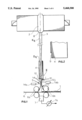
- FIG. 1 is a diagram of an apparatus in accordance with the present invention for producing a spun-filament nonwoven web
- FIG. 2 is a detail of the region II of FIG. 1 greatly enlarged in scale
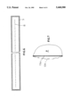
- FIG. 3 is a perspective view of a portion of the stretching nozzle of the apparatus of the invention.
- FIG. 4. is a section taken along the line IV--IV of FIG. 3;
- FIG. 5 is a diagrammatic sectional view of a portion of the blowing head
- FIG. 6 is a sectional view through a cooling chamber showing the rectangular configuration thereof.
- FIG. 7 is a detail view illustrating one of the principles of the invention.
- the apparatus shown in the drawing for the production of a spun-filament nonwoven web 1 from aerodynamically stretched filaments or strands of thermoplastic synthetic resin comprises basically a spinning head 2, a cooling chamber 3 below the spinning head 2, a stretching nozzle 4 located below the cooling chamber 3, a filament-delivery unit 5 located below the stretching nozzle 4, a perforated sieve belt 6 which may be an endless belt, collecting the web 1 below the delivery unit 5, and a suction source or suction blower 7.
- the spinning head 2 can comprise a nozzle or orifice plate 2a, also referred to as a spinneret, with orifices 2b from which liquid strands 8a of thermoplastic synthetic resin issue in a curtain of filaments 8 which can be a single row of filaments where the curtain issues at 2c from the head 2 and is wider at its upper end.
- Initial quenching may be carried out in a compartment 2c to which quenching air is fed from ducts 2e. A portion of the air can be discharged through ducts 2f while the balance accompanies the curtain of filaments 8 into the cooling chamber 3.
- swingable flaps 2g may be provided at the outlet side of the chamber 2d.
- the cooling chamber 3 has a rectangular horizontal cross section which decreases in the flow direction, namely, downwardly.
- This flow cross section is represented at k q and as has been indicated previously, the smallest cross section K q is greater than the smallest cross section D q of the stretching nozzle 4 below the cooling chamber 3 and connected therewith.
- FIG. 6 shows the cross section of the cooling chamber 3 which, of course, is geometrically similar to the cross section of the stretching nozzle 4.
- a wall 13a defining the stretching nozzle gap and which might bulge or fluctuate by reason of aerodynamic forces in the gap and as shown in dot-dash lines in 13b in FIG. 7, can be prevented from so shifting by control of the pressure P in the boxlike structure behind each wall 13a.
- the sheet metal walls 13a may be caused to bulge, if desired, when the pressure P is used to control the gap width in the gap of the stretching nozzle 4.
- the filament-delivery unit 5 is provided below and separate from the stretching nozzle 4 and is constituted in the form of a jet pump with, in the vertical direction, a ventori-like intake 10, a diffuser outlet 11 and a constriction between the intake and outlet. At least one free air-intake opening 12 is provided in the region of the inlet 10j.
- the web 1 is deposited upon the sieve belt 6 which continuously moves below the delivery unit 5 which can have a pair of rollers 6a at the upstream side and a pair of rollers 6b at the downstream side of the region in which the web is deposited, to confine the spaces in this region so that suction drawn by the suction source 7 below the belt 6 can draw air in through the gap 12 and through the jet nozzle forming the delivery unit.
- a suction blower 7a of adjustable throughput is shown to be connected to the duct 7 to constitute the source.
- the air flow through the jet pump can be controlled or regulated.
- the double-headed arrow in FIG. 3 represents the nozzle cross section D q .
- the nozzle 4 is provided as a boxlike structure with walls 13 of sheet metal which can be deformed by the controllable pressure sources represented at 13c and 13d to control the gap or for regulating the pressure within the boxlike structures so as to prevent fluctuation of the wall 13 under the aerodynamic pressure.
- the jet pump has walls 14 which define the gap thereof and can be controlled in position by servomotors 14a and 14b or the like, to thereby influence the flow cross section through the jet pump.
- the smallest cross section D q should be between 0.9 K q and 0.01 K q in the best mode of carrying out the invention in practice.
Abstract
A spun-filament nonwoven web is deposited on a sieve belt from a spinning head producing a curtain of thermoplastic filaments which traverse a cooling chamber by drawing the filaments in a drawing nozzle separate from the cooling chamber and passing the filaments through a delivery unit and in the form of a jet pump, air flow through which is controlled at least in part by a suction blower below that sieve belt.
Description
Our present invention relates to an apparatus for producing a nonwoven spun-filament web of aerodynamically stretched filaments of a thermoplastic synthetic resin. More particularly the invention relates to an apparatus which is capable of producing such nonwoven webs at a higher rate, with greater reliability and more uniform properties than has hitherto been the case.
An apparatus for producing a spun fleece or nonwoven web of stretched filaments of thermoplastic synthetic resin generally comprises a spinning head from which a curtain of the filaments emerges, a cooling chamber below the spinning head within which the filaments are quenched, a stretching nozzle below the cooling chamber and a sieve or perforated belt upon which the filaments are deposited to form the nonwoven web. A suction source can be located below the belt for drawing air through the belt and assisting in the depositing of the nonwoven web.
Apparatus of this type and for these purposes is available in various configurations. They must, however, generally satisfy two basic requirements, namely high output in terms of the spun fleece web which is produced per unit time and the maintenance of certain quality parameters of the web within narrow tolerances.
In the apparatus described in U.S. Pat. No. 4,405,297, the stretching nozzle is a gap with a comparatively large gap width, defined by a gap-forming wall which extends substantially up to the spinning head, and another wall which is inclined toward the first wall to form a wedge-shaped cooling chamber therewith and which extends to a point at which process air can be admitted.
A special fleece deposition unit is not here provided and the stretching nozzle in the form of the gap simultaneously constitutes the fleece-deposition device.
As a consequence, a relatively large gap width is required and the gap width must be adjustable up to say 45 mm in practice.
To maintain a predetermined stable operating state with the desired output, a certain process air flow rate is required. When the output is to be increased, the process air flow rate must be increased and in practice it is found that the ability to change the process air flow rate is highly limited if quality parameters of the nonwoven web are to be maintained.
In another apparatus (see DE 40 14 989 A1), the cooling chamber has a decreasing cross section in the direction of travel of the filaments and a cross section which is rectangular in horizontal section, the cooling chamber feeding into a venturi-like constriction whose narrowest part is followed by a diffuser outlet. Here as well a special fleece-deposition unit is not provided.
The venturi constriction serves as a stretching nozzle and is shaped aerodynamically in a corresponding manner. In the transition region between the cooling chamber and the stretching nozzle a free air inlet gap is provided. An effect upon the deposition of the fleece on the sieve belt was obtained by adjustable flaps in the flow passages of the apparatus. If one attempts to increase the output starting from a stable operating state, the process air flow rate must also increase here. This gives rise to problems when deterioration of the quality parameter of the spun-fleece web is to be avoided.
It is, therefore, the principal object of the present invention to provide an apparatus of the aforedescribed construction and for the purposes described so that a significant increase in output is possible without detriment to the quality parameter of the nonwoven web.
It is also an object of this invention to provide an apparatus for the purposes described which is free from drawbacks of earlier systems.
These objects and others which will become apparent hereinafter are attained, in accordance with the invention, in an apparatus which comprises:
a filament spinning head provided with a multiplicity of spinning orifices discharging respective strands of thermoplastic synthetic resin in at least one row to form a descending curtain of the strands;
a vertically extending cooling chamber below the filament spinning head receiving the curtain for quenching same and having a rectangular cross section in horizontal planes decreasing downwardly to a smallest cross section Kq at a lower end of the cooling chamber;
a stretching nozzle adjacent the lower end of the cooling chamber and extending downwardly therefrom, the stretching nozzle having opposite walls flanking the curtain and between which the strands are aerodynamically stretched by entrainment with air through the stretching nozzle, the stretching nozzle having a rectangular flow cross section Dq in a horizontal plane which is smaller by a factor of 0.9 to 0.01 than the smallest cross section Kq at the lower end of the cooling chamber so that Dq is substantially equal to 0.9 Kq to 0.01 Kq ;
a setback formed on a lower end of at least one of the walls;
a filament delivery unit below the stretching nozzle and receiving the strands therefrom, the filament delivery nozzle including a vertically disposed jet pump having an inlet at an upper end, a venturi constriction below the inlet and a diffusor outlet below and connected with the constriction, the jet pump having a flow passage section between the inlet and the outlet which is rectangular in horizontal cross section, the inlet being open to ambient atmosphere whereby ambient air is drawn through the unit;
a continuously movable sieve belt below the filament delivery unit receiving the filaments therefrom in a nonwoven web, the nonwoven web being carried away from the filament delivery unit on the belt; and
a controllable flow rate suction source below the belt and the filament delivery unit and communicating with the filament delivery unit through the belt for regulating air flow through the jet pump.
The spinning head can have a multiplicity of spinning orifices arranged in at least one and preferably a plurality of rows so that the curtain passes from a broad selection of orifices into at least a single row of the strands of thermoplastic synthetic resin.
The suction source or suction blower below the sieve belt serves to regulate at least in part the quantity of air which is drawn through the filament delivery unit so that this air quantity is controllable or regulatable by the suction blower.
The invention is based upon our finding that, to increase the output for an apparatus of the aforedescribed type, the stretching function on the one hand and the filament delivery on the other must be separated and must utilize separate apparatus components.
It must be emphasized that all of the features set forth must be present, including the stretching nozzle separate from the cooling chamber and the filament delivery unit and the setback or setbacks formed on the lower end of one or both of the walls defining the stretching nozzle. Surprisingly, with this combination of features, the acceleration resulting from the process air drawn through the stretching nozzle allows a filament speed of 2000 m/min or more to be achieved. The limited gap width of the stretching nozzle reduces the volume of process air which must traverse the stretching nozzle while nevertheless allowing high velocities to be achieved.
Detrimental contacts of the filaments with the nozzle-forming walls of the stretching nozzle do not occur because of the setbacks at the outlet side of the stretching nozzle and thus the reduction in quality of the nonwoven web which might result from such contact is avoided.
Since the filament-delivery unit is in the form of a jet pump and the suction flow is generated by a suction blower beneath the sieve belt, nonwoven spun fleece webs can be produced which satisfy all of the desirable quality characteristics.
The stretching nozzle can have a nozzle cross section or thickness which is not permitted to vary by reason of fluctuations in the position of the nozzle-forming walls as may result from the passage of process air therethrough. To this end, the stretching nozzle can have a box-like configuration with nozzle walls composed of sheet metal and the deformations of the nozzle walls by the aerostatic pressure in the gap being balanced by a controllable or regulatable internal pressure of the box-like structure.
According to a feature of the invention, the filament delivery unit has adjustable side walls so that the air flow drawn through the jet pump can be additionally influenced. The jet pump, of course, can extend the full width of the curtain of filaments and be operated by the air stream emerging from the stretching nozzle as has also been influenced or effected by the suction blower below the perforated belt.
As has previously been indicated, the apparatus of the invention allows high throughputs to be achieved together with high levels of the quality parameter of the nonwoven web. It is of special significance that the filament speed can be up to or in excess of 2000 m/min.
The above and other objects, features, and advantages will become more readily apparent from the following description, reference being made to the accompanying drawing in which:
FIG. 1 is a diagram of an apparatus in accordance with the present invention for producing a spun-filament nonwoven web;
FIG. 2 is a detail of the region II of FIG. 1 greatly enlarged in scale;
FIG. 3 is a perspective view of a portion of the stretching nozzle of the apparatus of the invention;
FIG. 4. is a section taken along the line IV--IV of FIG. 3;
FIG. 5 is a diagrammatic sectional view of a portion of the blowing head;
FIG. 6 is a sectional view through a cooling chamber showing the rectangular configuration thereof; and
FIG. 7 is a detail view illustrating one of the principles of the invention.
The apparatus shown in the drawing for the production of a spun-filament nonwoven web 1 from aerodynamically stretched filaments or strands of thermoplastic synthetic resin comprises basically a spinning head 2, a cooling chamber 3 below the spinning head 2, a stretching nozzle 4 located below the cooling chamber 3, a filament-delivery unit 5 located below the stretching nozzle 4, a perforated sieve belt 6 which may be an endless belt, collecting the web 1 below the delivery unit 5, and a suction source or suction blower 7.
As can be seen from FIG. 5, the spinning head 2 can comprise a nozzle or orifice plate 2a, also referred to as a spinneret, with orifices 2b from which liquid strands 8a of thermoplastic synthetic resin issue in a curtain of filaments 8 which can be a single row of filaments where the curtain issues at 2c from the head 2 and is wider at its upper end. Initial quenching may be carried out in a compartment 2c to which quenching air is fed from ducts 2e. A portion of the air can be discharged through ducts 2f while the balance accompanies the curtain of filaments 8 into the cooling chamber 3. At the outlet side of the chamber 2d, swingable flaps 2g may be provided.
The cooling chamber 3 has a rectangular horizontal cross section which decreases in the flow direction, namely, downwardly. This flow cross section is represented at kq and as has been indicated previously, the smallest cross section Kq is greater than the smallest cross section Dq of the stretching nozzle 4 below the cooling chamber 3 and connected therewith.
FIG. 6 shows the cross section of the cooling chamber 3 which, of course, is geometrically similar to the cross section of the stretching nozzle 4.
From FIG. 2 it will be apparent that at the discharge end of the stretching nozzle 4, the walls 13 which define it are provided with setbacks as shown at 9. The depth of the setback is less than the gap width defined by the nozzle 4.
Furthermore, as will be apparent from FIG. 7, a wall 13a defining the stretching nozzle gap and which might bulge or fluctuate by reason of aerodynamic forces in the gap and as shown in dot-dash lines in 13b in FIG. 7, can be prevented from so shifting by control of the pressure P in the boxlike structure behind each wall 13a.
Furthermore, and as will be apparent from the discussion of FIG. 4, the sheet metal walls 13a may be caused to bulge, if desired, when the pressure P is used to control the gap width in the gap of the stretching nozzle 4.
According to the invention, the filament-delivery unit 5 is provided below and separate from the stretching nozzle 4 and is constituted in the form of a jet pump with, in the vertical direction, a ventori-like intake 10, a diffuser outlet 11 and a constriction between the intake and outlet. At least one free air-intake opening 12 is provided in the region of the inlet 10j.
As will be apparent further from FIG. 1, the web 1 is deposited upon the sieve belt 6 which continuously moves below the delivery unit 5 which can have a pair of rollers 6a at the upstream side and a pair of rollers 6b at the downstream side of the region in which the web is deposited, to confine the spaces in this region so that suction drawn by the suction source 7 below the belt 6 can draw air in through the gap 12 and through the jet nozzle forming the delivery unit. A suction blower 7a of adjustable throughput is shown to be connected to the duct 7 to constitute the source.
Thus with the aid of the suction source 7, 7a, the air flow through the jet pump can be controlled or regulated.
The double-headed arrow in FIG. 3 represents the nozzle cross section Dq.
From a comparison of FIGS. 3 and 4, one can see that the nozzle 4 is provided as a boxlike structure with walls 13 of sheet metal which can be deformed by the controllable pressure sources represented at 13c and 13d to control the gap or for regulating the pressure within the boxlike structures so as to prevent fluctuation of the wall 13 under the aerodynamic pressure.
The jet pump has walls 14 which define the gap thereof and can be controlled in position by servomotors 14a and 14b or the like, to thereby influence the flow cross section through the jet pump.
The smallest cross section Dq should be between 0.9 Kq and 0.01 Kq in the best mode of carrying out the invention in practice.
Claims (2)
1. An apparatus for producing a spun-filament nonwoven web of thermoplastic synthetic resin, comprising:
a filament spinning head provided with a multiplicity of spinning orifices discharging respective strands of thermoplastic synthetic resin in at least one row to form a descending curtain of said strands;
a vertically extending cooling chamber below said filament spinning head receiving said curtain for quenching same and having a rectangular cross section in horizontal planes decreasing downwardly to a smallest cross section Kq at a lower end of said cooling chamber;
a stretching nozzle adjacent said lower end of said cooling chamber and extending downwardly therefrom, said stretching nozzle having opposite walls defining a gap width flanking said curtain and between which said strands are aerodynamically stretched by entrainment with air through said stretching nozzle, said stretching nozzle having a rectangular flow cross section Dq in a horizontal plane which is smaller by a factor of 0.9 to 0.01 than said smallest cross section Kq at said lower end of said cooling chamber so that Dq is substantially equal to 0.9 Kq to 0.01 Kq ;
a setback formed on a lower end of at least one of said walls;
a filament delivery unit below said stretching nozzle and receiving said strands therefrom, said filament delivery unit including a vertically disposed jet pump having an inlet at an upper end, a venturi constriction below said inlet and a diffusor outlet below and connected with said venturi constriction, said vertically disposed jet pump having a flow passage section between said inlet and said outlet which is rectangular in horizontal cross section, said inlet being open to ambient atmosphere whereby ambient air is drawn through said filament delivery unit;
a continuously movable sieve belt below said filament delivery unit receiving said strands therefrom in a nonwoven web, said nonwoven web being carried away from said filament delivery unit on said sieve belt;
a controllable flow rate suction source below said sieve belt and said filament delivery unit and communicating with said filament delivery unit through said sieve belt for regulating air flow through said vertically disposed jet pump; and
means for varying the gap width of said stretching nozzle comprising a boxlike structure behind each wall and means in said boxlike structure for varying an internal pressure therein to compensate for aerostatic tendencies for deformation of said walls resulting from flow of air through said stretching nozzle.
2. The apparatus defined in claim 1 wherein said filament delivery unit has shiftable walls additionally controlling airflow therethrough by position of the shiftable walls.
Applications Claiming Priority (2)
| Application Number | Priority Date | Filing Date | Title |
|---|---|---|---|
| DE4312419A DE4312419C2 (en) | 1993-04-16 | 1993-04-16 | Plant for the production of a spunbonded nonwoven web from aerodynamically stretched plastic filaments |
| DE4312419.4 | 1993-04-16 |
Publications (1)
| Publication Number | Publication Date |
|---|---|
| US5460500A true US5460500A (en) | 1995-10-24 |
Family
ID=6485600
Family Applications (1)
| Application Number | Title | Priority Date | Filing Date |
|---|---|---|---|
| US08/227,977 Expired - Lifetime US5460500A (en) | 1993-04-16 | 1994-04-15 | Apparatus for producing a nonwoven spun-filament web of aerodynamically stretched filament of a plastic |
Country Status (6)
| Country | Link |
|---|---|
| US (1) | US5460500A (en) |
| JP (1) | JP2556953B2 (en) |
| CN (1) | CN1094463A (en) |
| CA (1) | CA2121383C (en) |
| DE (1) | DE4312419C2 (en) |
| IT (1) | IT1273401B (en) |
Cited By (49)
| Publication number | Priority date | Publication date | Assignee | Title |
|---|---|---|---|---|
| US5571537A (en) * | 1994-04-23 | 1996-11-05 | Reifenhauser Gmbh & Co. Maschinenfabrik | Stationary-pressure apparatus for producing spun-bond web |
| US5609808A (en) * | 1995-01-17 | 1997-03-11 | Reifenhauser Gmbh & Co. Maschinenfabrik | Method of making a fleece or mat of thermoplastic polymer filaments |
| US5766646A (en) * | 1995-06-13 | 1998-06-16 | Reifenhauser Gmbh & Co. Maschinenfabrik | Apparatus for making a fleece from continuous thermoplastic filaments |
| US5814349A (en) * | 1996-05-21 | 1998-09-29 | Reifenhauser Gmbh & Co. Maschinenfabrik | Apparatus for the continuous production of a spun-bond web |
| EP1079012A1 (en) * | 1999-08-25 | 2001-02-28 | Reifenhäuser GmbH & Co. Maschinenfabrik | Apparatus for producing a spunbonded web from synthetic filaments |
| EP1138813A1 (en) * | 2000-03-30 | 2001-10-04 | Uni-Charm Corporation | Process for making non woven fabric and apparatus used for this process |
| US6331268B1 (en) | 1999-08-13 | 2001-12-18 | First Quality Nonwovens, Inc. | Nonwoven fabric with high CD elongation and method of making same |
| EP1170411A1 (en) * | 2000-07-05 | 2002-01-09 | Uni-Charm Corporation | Apparatus for making nonwoven fabric |
| US6379136B1 (en) * | 1999-06-09 | 2002-04-30 | Gerald C. Najour | Apparatus for production of sub-denier spunbond nonwovens |
| WO2002055782A2 (en) * | 2000-11-20 | 2002-07-18 | 3M Innovative Properties Company | Fiber-forming process |
| US6468063B1 (en) * | 1999-07-15 | 2002-10-22 | Uni-Charm Corporation | Cold drawing apparatus |
| US20020155185A1 (en) * | 2001-04-18 | 2002-10-24 | Satoru Tange | Apparatus for making web comprising continuous fibers |
| US20030003834A1 (en) * | 2000-11-20 | 2003-01-02 | 3M Innovative Properties Company | Method for forming spread nonwoven webs |
| US20030057586A1 (en) * | 2001-09-26 | 2003-03-27 | Bba Nonwovens Simpsonville, Inc. | Apparatus and method for producing a nonwoven web of filaments cross-reference to related application |
| US20030085493A1 (en) * | 2000-12-28 | 2003-05-08 | Nordson Corporation | Air management method for the manufacture of nonwoven webs and laminates |
| US20030147982A1 (en) * | 2002-02-07 | 2003-08-07 | Nordson Corporation | Forming system for the manufacture of thermoplastic nonwoven webs and laminates |
| US6607624B2 (en) | 2000-11-20 | 2003-08-19 | 3M Innovative Properties Company | Fiber-forming process |
| US20030161904A1 (en) * | 2002-02-28 | 2003-08-28 | Reifenhauser Gmbh & Co. Maschinenfabrik | Apparatus for the continuous production of spun-bond web |
| US20030178742A1 (en) * | 2002-02-28 | 2003-09-25 | Reifenhauser Gmbh & Co. Maschinenfabrik | Arrangement for the continuous production of a filament nonwoven fibrous web |
| US20030216096A1 (en) * | 2002-05-20 | 2003-11-20 | 3M Innovative Properties Company | Bondable, oriented, nonwoven fibrous webs and methods for making them |
| US20040011471A1 (en) * | 2000-10-20 | 2004-01-22 | Laurent Schmit | Installation for producing a spunbonded fabric web whereof the diffuser in distant form the drawing slot device |
| US20040028763A1 (en) * | 2000-10-20 | 2004-02-12 | Laurent Schmit | Installation for producing a spunbonded fabric web with filament diffuser and separation by electrostatic process |
| US20040086588A1 (en) * | 2002-11-01 | 2004-05-06 | Haynes Bryan David | Fiber draw unit nozzles for use in polymer fiber production |
| EP1431435A1 (en) * | 2002-12-19 | 2004-06-23 | Reifenhäuser GmbH & Co. Maschinenfabrik | Apparatus for depositing and transporting a nonwoven web of synthetic filaments |
| US20040219242A1 (en) * | 2001-05-31 | 2004-11-04 | Rosario Maggio | Installation for producing a nonwoven web with very uniform weight |
| US20050087287A1 (en) * | 2003-10-27 | 2005-04-28 | Lennon Eric E. | Method and apparatus for the production of nonwoven web materials |
| US20050106982A1 (en) * | 2003-11-17 | 2005-05-19 | 3M Innovative Properties Company | Nonwoven elastic fibrous webs and methods for making them |
| KR100493981B1 (en) * | 2001-12-17 | 2005-06-13 | 라이펜호이저 게엠베하 운트 코. 마쉬넨파브릭 | Apparatus for producing spunbonded web from aerodynamic drafting filament of thermoplastic plastics |
| US6966762B1 (en) * | 1999-04-23 | 2005-11-22 | Rieter Perfojet | Device for opening and distributing a bundle of filaments when producing a nonwoven textile web |
| US7179412B1 (en) | 2001-01-12 | 2007-02-20 | Hills, Inc. | Method and apparatus for producing polymer fibers and fabrics including multiple polymer components in a closed system |
| US7279440B2 (en) | 2002-05-20 | 2007-10-09 | 3M Innovative Properties Company | Nonwoven amorphous fibrous webs and methods for making them |
| US20080230943A1 (en) * | 2007-03-19 | 2008-09-25 | Conrad John H | Method and apparatus for enhanced fiber bundle dispersion with a divergent fiber draw unit |
| US20080256757A1 (en) * | 2005-10-26 | 2008-10-23 | Oerlikon Textile Gmbh & Co. Kg | Apparatus and method for depositing synthetic fibers to form a nonwoven |
| US20080317895A1 (en) * | 2004-09-24 | 2008-12-25 | Galliano Boscolo | Device for Stacking Synthetic Fibers to Form a Nonwoven |
| US20090004313A1 (en) * | 2007-06-29 | 2009-01-01 | Hans-Georg Geus | Apparatus for making a spunbond web |
| US20090136606A1 (en) * | 2003-12-20 | 2009-05-28 | Fiberweb Corovin Gmbh | Device for the manufacture of polyethylene-based, soft nonwoven fabric |
| US20090256278A1 (en) * | 2006-11-10 | 2009-10-15 | Oerlikon Textile Gmbh & Co. Kg | Process and device for melt-spinning and cooling synthetic filaments |
| US20090321982A1 (en) * | 2007-01-19 | 2009-12-31 | Oerlikon Textile Gmbh & Co. Kg | Apparatus and method for depositing synthetic fibers to form a non-woven web |
| US8226597B2 (en) | 2002-06-21 | 2012-07-24 | Baxter International, Inc. | Fluid delivery system and flow control therefor |
| EP2778270A1 (en) | 2013-03-15 | 2014-09-17 | Fibertex Personal Care A/S | Nonwoven substrates having fibrils |
| WO2014145608A1 (en) | 2013-03-15 | 2014-09-18 | The Procter & Gamble Company | Packages for articles of commerce |
| DE102014103393A1 (en) | 2013-03-15 | 2014-09-18 | The Procter & Gamble Company | nonwoven substrates |
| WO2014150303A1 (en) | 2013-03-15 | 2014-09-25 | The Procter & Gamble Company | Absorbent articles with nonwoven substrates having fibrils |
| WO2014150316A1 (en) | 2013-03-15 | 2014-09-25 | The Procter & Gamble Company | Wipes with improved properties |
| WO2014151480A1 (en) | 2013-03-15 | 2014-09-25 | The Procter & Gamble Company | Methods for forming absorbent articles with nonwoven substrates |
| US9840794B2 (en) | 2008-12-30 | 2017-12-12 | 3M Innovative Properties Compnay | Elastic nonwoven fibrous webs and methods of making and using |
| US20180282926A1 (en) * | 2017-03-31 | 2018-10-04 | Reifenhaeuser Gmbh & Co. Kg Maschinenfabrik | Apparatus for making spunbond from continuous filaments |
| CN108728912A (en) * | 2018-07-10 | 2018-11-02 | 睢宁县同佳化纤厂 | A kind of chemical fibre spinneret plate structure |
| US20210172104A1 (en) * | 2017-03-31 | 2021-06-10 | Detlef Frey | Apparatus for making spunbond |
Families Citing this family (10)
| Publication number | Priority date | Publication date | Assignee | Title |
|---|---|---|---|---|
| DE19607114A1 (en) * | 1995-01-28 | 1996-12-05 | Lueder Dr Ing Gerking | Filament melt spinning |
| DE19612142C1 (en) * | 1996-03-27 | 1997-10-09 | Reifenhaeuser Masch | Spun-bond nonwoven web laying assembly |
| EP1486591B1 (en) * | 2003-06-13 | 2005-11-16 | Reifenhäuser GmbH & Co. KG Maschinenfabrik | Apparatus for the production of filaments |
| DE102006057367A1 (en) * | 2006-12-04 | 2008-06-05 | Fleissner Gmbh | Water suction chamber for textile jet processing bar also discharges air screen jet in vicinity of water jet |
| CN101092758B (en) * | 2007-06-05 | 2010-11-10 | 东华大学 | Module type air draft equipment in non-woven product line of spinning viscose |
| CN101831721A (en) * | 2010-05-28 | 2010-09-15 | 新乡化纤股份有限公司 | Flat fiber spray nozzle |
| CN107190424A (en) * | 2016-03-15 | 2017-09-22 | 常州阿尔丰机械有限公司 | A kind of nonwoven production diffuser and its method of work |
| JPWO2017170242A1 (en) | 2016-03-30 | 2018-10-04 | 三井化学株式会社 | Nonwoven fabric manufacturing apparatus and nonwoven fabric manufacturing method |
| PL3382082T3 (en) * | 2017-03-31 | 2020-03-31 | Reifenhäuser GmbH & Co. KG Maschinenfabrik | Device for the manufacture of woven material from continuous filaments |
| CN111254587A (en) * | 2020-04-21 | 2020-06-09 | 大连天马可溶制品有限公司 | Triangular box type net laying device |
Citations (10)
| Publication number | Priority date | Publication date | Assignee | Title |
|---|---|---|---|---|
| US3929542A (en) * | 1970-11-03 | 1975-12-30 | Basf Farben & Fasern | Non-woven webs of filaments of synthetic high molecular weight polymers and process for the manufacture thereof |
| US4340563A (en) * | 1980-05-05 | 1982-07-20 | Kimberly-Clark Corporation | Method for forming nonwoven webs |
| US4405297A (en) * | 1980-05-05 | 1983-09-20 | Kimberly-Clark Corporation | Apparatus for forming nonwoven webs |
| EP0224435A2 (en) * | 1985-11-21 | 1987-06-03 | J. H. Benecke AG | Method for making a fleece of continuous filaments, and apparatus for carrying out this method |
| US4692106A (en) * | 1985-02-05 | 1987-09-08 | Reifenhauser Gmbh & Co. Maschinenfabrik | Apparatus for stretching the individual strands of a bundle of fibers or threads |
| US4812112A (en) * | 1987-04-25 | 1989-03-14 | Reifenhauser Gmbh & Co. Maschinenfabrik | Apparatus for making a spun fleece from endless synthetic-resin filament |
| US4813864A (en) * | 1987-04-25 | 1989-03-21 | Reifenhauser Gmbh & Co. Maschinenfabrik | Apparatus for making a spun-filament fleece |
| US4820142A (en) * | 1987-04-25 | 1989-04-11 | Reifenhauser Gmbh & Co. Maschinenfabrik | Apparatus for making a spun-filament fleece |
| US4838774A (en) * | 1987-01-21 | 1989-06-13 | Reifenhauser Gmbh & Co Maschinenfabrik | Apparatus for making a spun-filament fleece |
| DE4014989A1 (en) * | 1990-05-10 | 1991-11-14 | Reifenhaeuser Masch | Mfr. of spin-drawn synthetic fibre filament batt - has separate supplies for cooling air and for process fluid in drawing nozzle |
Family Cites Families (2)
| Publication number | Priority date | Publication date | Assignee | Title |
|---|---|---|---|---|
| US3766606A (en) * | 1972-04-19 | 1973-10-23 | Du Pont | Apparatus for forwarding tow |
| DD110678A1 (en) * | 1974-03-12 | 1975-01-05 |
-
1993
- 1993-04-16 DE DE4312419A patent/DE4312419C2/en not_active Expired - Lifetime
-
1994
- 1994-03-31 IT ITMI940624A patent/IT1273401B/en active IP Right Grant
- 1994-04-13 CN CN94104585A patent/CN1094463A/en active Pending
- 1994-04-14 JP JP6076031A patent/JP2556953B2/en not_active Expired - Lifetime
- 1994-04-15 CA CA002121383A patent/CA2121383C/en not_active Expired - Lifetime
- 1994-04-15 US US08/227,977 patent/US5460500A/en not_active Expired - Lifetime
Patent Citations (14)
| Publication number | Priority date | Publication date | Assignee | Title |
|---|---|---|---|---|
| US3929542A (en) * | 1970-11-03 | 1975-12-30 | Basf Farben & Fasern | Non-woven webs of filaments of synthetic high molecular weight polymers and process for the manufacture thereof |
| US4340563A (en) * | 1980-05-05 | 1982-07-20 | Kimberly-Clark Corporation | Method for forming nonwoven webs |
| US4405297A (en) * | 1980-05-05 | 1983-09-20 | Kimberly-Clark Corporation | Apparatus for forming nonwoven webs |
| US4692106A (en) * | 1985-02-05 | 1987-09-08 | Reifenhauser Gmbh & Co. Maschinenfabrik | Apparatus for stretching the individual strands of a bundle of fibers or threads |
| EP0224435A2 (en) * | 1985-11-21 | 1987-06-03 | J. H. Benecke AG | Method for making a fleece of continuous filaments, and apparatus for carrying out this method |
| US4838774A (en) * | 1987-01-21 | 1989-06-13 | Reifenhauser Gmbh & Co Maschinenfabrik | Apparatus for making a spun-filament fleece |
| US5028375A (en) * | 1987-01-21 | 1991-07-02 | Reifenhauser Gmbh & Co. Maschinenfabrik | Process for making a spun-filament fleece |
| US4813864A (en) * | 1987-04-25 | 1989-03-21 | Reifenhauser Gmbh & Co. Maschinenfabrik | Apparatus for making a spun-filament fleece |
| US4820142A (en) * | 1987-04-25 | 1989-04-11 | Reifenhauser Gmbh & Co. Maschinenfabrik | Apparatus for making a spun-filament fleece |
| US4820459A (en) * | 1987-04-25 | 1989-04-11 | Reifenhauser Gmbh & Co. Maschinenfabrik | Process for making spun-filament fleece from endless synthetic resin filament |
| US4812112A (en) * | 1987-04-25 | 1989-03-14 | Reifenhauser Gmbh & Co. Maschinenfabrik | Apparatus for making a spun fleece from endless synthetic-resin filament |
| US4851179A (en) * | 1987-04-25 | 1989-07-25 | Reifenhauser Gmbh & Co. Maschinenfabrik | Method of operating a fleece-making apparatus |
| US5032329A (en) * | 1987-04-25 | 1991-07-16 | Reifenhauser Gmbh & Co. Maschinenfabrik | Method of making a fleece from spun filaments |
| DE4014989A1 (en) * | 1990-05-10 | 1991-11-14 | Reifenhaeuser Masch | Mfr. of spin-drawn synthetic fibre filament batt - has separate supplies for cooling air and for process fluid in drawing nozzle |
Cited By (98)
| Publication number | Priority date | Publication date | Assignee | Title |
|---|---|---|---|---|
| US5571537A (en) * | 1994-04-23 | 1996-11-05 | Reifenhauser Gmbh & Co. Maschinenfabrik | Stationary-pressure apparatus for producing spun-bond web |
| US5609808A (en) * | 1995-01-17 | 1997-03-11 | Reifenhauser Gmbh & Co. Maschinenfabrik | Method of making a fleece or mat of thermoplastic polymer filaments |
| US5766646A (en) * | 1995-06-13 | 1998-06-16 | Reifenhauser Gmbh & Co. Maschinenfabrik | Apparatus for making a fleece from continuous thermoplastic filaments |
| US5814349A (en) * | 1996-05-21 | 1998-09-29 | Reifenhauser Gmbh & Co. Maschinenfabrik | Apparatus for the continuous production of a spun-bond web |
| US6966762B1 (en) * | 1999-04-23 | 2005-11-22 | Rieter Perfojet | Device for opening and distributing a bundle of filaments when producing a nonwoven textile web |
| US6379136B1 (en) * | 1999-06-09 | 2002-04-30 | Gerald C. Najour | Apparatus for production of sub-denier spunbond nonwovens |
| US6468063B1 (en) * | 1999-07-15 | 2002-10-22 | Uni-Charm Corporation | Cold drawing apparatus |
| US6331268B1 (en) | 1999-08-13 | 2001-12-18 | First Quality Nonwovens, Inc. | Nonwoven fabric with high CD elongation and method of making same |
| EP1079012A1 (en) * | 1999-08-25 | 2001-02-28 | Reifenhäuser GmbH & Co. Maschinenfabrik | Apparatus for producing a spunbonded web from synthetic filaments |
| CZ298976B6 (en) * | 1999-08-25 | 2008-03-26 | REIFENHäUSER GMBH & CO. MASCHINENFABRIK | Apparatus for producing spunbonded nonwoven fabric composed of synthetic resin filament |
| US6402492B1 (en) | 1999-08-25 | 2002-06-11 | Reifenhauser Gmbh & Co. Maschinenfabrik | Apparatus for producing spun bond |
| AU778577B2 (en) * | 2000-03-30 | 2004-12-09 | Uni-Charm Corporation | Process for making nonwoven fabric and apparatus used for this process |
| EP1138813A1 (en) * | 2000-03-30 | 2001-10-04 | Uni-Charm Corporation | Process for making non woven fabric and apparatus used for this process |
| US6663823B2 (en) | 2000-03-30 | 2003-12-16 | Uni-Charm Corporation | Process for making nonwoven fabric and apparatus used for this process |
| EP1170411A1 (en) * | 2000-07-05 | 2002-01-09 | Uni-Charm Corporation | Apparatus for making nonwoven fabric |
| US6663373B2 (en) | 2000-07-05 | 2003-12-16 | Uni-Charm Corporation | Apparatus for making nonwoven fabric |
| US6979186B2 (en) * | 2000-10-20 | 2005-12-27 | Reiter Perfojet | Installation for producing a spunbonded fabric web with filament diffuser and separation by electrostatic process |
| US7008205B2 (en) * | 2000-10-20 | 2006-03-07 | Rieter Perfojet | Installation for producing a spunbonded fabric web whereof the diffuser is distant from the drawing slot device |
| US20040028763A1 (en) * | 2000-10-20 | 2004-02-12 | Laurent Schmit | Installation for producing a spunbonded fabric web with filament diffuser and separation by electrostatic process |
| US20040011471A1 (en) * | 2000-10-20 | 2004-01-22 | Laurent Schmit | Installation for producing a spunbonded fabric web whereof the diffuser in distant form the drawing slot device |
| WO2002055782A3 (en) * | 2000-11-20 | 2003-03-13 | 3M Innovative Properties Co | Fiber-forming process |
| US7470389B2 (en) | 2000-11-20 | 2008-12-30 | 3M Innovative Properties Company | Method for forming spread nonwoven webs |
| WO2002055782A2 (en) * | 2000-11-20 | 2002-07-18 | 3M Innovative Properties Company | Fiber-forming process |
| US20050140067A1 (en) * | 2000-11-20 | 2005-06-30 | 3M Innovative Properties Company | Method for forming spread nonwoven webs |
| KR100826547B1 (en) * | 2000-11-20 | 2008-05-02 | 쓰리엠 이노베이티브 프로퍼티즈 캄파니 | Fiber-forming process |
| CN100432316C (en) * | 2000-11-20 | 2008-11-12 | 3M创新有限公司 | Fiber-forming process |
| US6607624B2 (en) | 2000-11-20 | 2003-08-19 | 3M Innovative Properties Company | Fiber-forming process |
| US20030147983A1 (en) * | 2000-11-20 | 2003-08-07 | 3M Innovative Properties | Fiber-forming apparatus |
| US20030162457A1 (en) * | 2000-11-20 | 2003-08-28 | 3M Innovative Properties | Fiber products |
| US6824372B2 (en) | 2000-11-20 | 2004-11-30 | 3M Innovative Properties Company | Fiber-forming apparatus |
| US20030003834A1 (en) * | 2000-11-20 | 2003-01-02 | 3M Innovative Properties Company | Method for forming spread nonwoven webs |
| US20030085493A1 (en) * | 2000-12-28 | 2003-05-08 | Nordson Corporation | Air management method for the manufacture of nonwoven webs and laminates |
| EP1548167A1 (en) * | 2000-12-28 | 2005-06-29 | Nordson Corporation | An apparatus and method for forming a nonwoven web |
| US7001567B2 (en) | 2000-12-28 | 2006-02-21 | Nordson Corporation | Melt spinning apparatus and process for making nonwoven webs |
| US7740777B2 (en) | 2001-01-12 | 2010-06-22 | Hills, Inc. | Method and apparatus for producing polymer fibers and fabrics including multiple polymer components |
| US20070222099A1 (en) * | 2001-01-12 | 2007-09-27 | Hills, Inc. | Method and Apparatus for Producing Polymer Fibers and Fabrics Including Multiple Polymer Components |
| US7179412B1 (en) | 2001-01-12 | 2007-02-20 | Hills, Inc. | Method and apparatus for producing polymer fibers and fabrics including multiple polymer components in a closed system |
| US20020155185A1 (en) * | 2001-04-18 | 2002-10-24 | Satoru Tange | Apparatus for making web comprising continuous fibers |
| US6877970B2 (en) * | 2001-04-18 | 2005-04-12 | Uni-Charm Corporation | Apparatus for making web comprising continuous fibers |
| US20040219242A1 (en) * | 2001-05-31 | 2004-11-04 | Rosario Maggio | Installation for producing a nonwoven web with very uniform weight |
| US6974316B2 (en) * | 2001-05-31 | 2005-12-13 | Rieter Perfojet | Installation for producing a nonwoven web with very uniform weight |
| US20030057586A1 (en) * | 2001-09-26 | 2003-03-27 | Bba Nonwovens Simpsonville, Inc. | Apparatus and method for producing a nonwoven web of filaments cross-reference to related application |
| US6783722B2 (en) | 2001-09-26 | 2004-08-31 | Bba Nonwovens Simpsonville, Inc. | Apparatus and method for producing a nonwoven web of filaments |
| KR100493981B1 (en) * | 2001-12-17 | 2005-06-13 | 라이펜호이저 게엠베하 운트 코. 마쉬넨파브릭 | Apparatus for producing spunbonded web from aerodynamic drafting filament of thermoplastic plastics |
| US20050023711A1 (en) * | 2002-02-07 | 2005-02-03 | Nordson Corporation | Method for manufacturing thermoplastic nonwoven webs and laminates |
| US6799957B2 (en) | 2002-02-07 | 2004-10-05 | Nordson Corporation | Forming system for the manufacture of thermoplastic nonwoven webs and laminates |
| US7476350B2 (en) | 2002-02-07 | 2009-01-13 | Aktiengesellschaft Adolph Saurer | Method for manufacturing thermoplastic nonwoven webs and laminates |
| US20030147982A1 (en) * | 2002-02-07 | 2003-08-07 | Nordson Corporation | Forming system for the manufacture of thermoplastic nonwoven webs and laminates |
| CN1630740B (en) * | 2002-02-07 | 2010-05-05 | 阿克提恩格塞尓沙夫特阿道夫绍雷尓公司 | System and method for manufacturing nonwoven webs, and air amount regulator of the system |
| US6918750B2 (en) * | 2002-02-28 | 2005-07-19 | Reifenhauser Gmbh & Co. Maschinenfabrik | Arrangement for the continuous production of a filament nonwoven fibrous web |
| US6932590B2 (en) * | 2002-02-28 | 2005-08-23 | Reifenhauser Gmbh & Co. Maschinenfabrik | Apparatus for the continuous production of spun-bond web |
| US20030161904A1 (en) * | 2002-02-28 | 2003-08-28 | Reifenhauser Gmbh & Co. Maschinenfabrik | Apparatus for the continuous production of spun-bond web |
| US20030178742A1 (en) * | 2002-02-28 | 2003-09-25 | Reifenhauser Gmbh & Co. Maschinenfabrik | Arrangement for the continuous production of a filament nonwoven fibrous web |
| WO2003100141A1 (en) * | 2002-05-20 | 2003-12-04 | 3M Innovative Properties Company | Bondable, oriented, nonwoven fibrous webs and methods for making them |
| US7695660B2 (en) | 2002-05-20 | 2010-04-13 | 3M Innovative Properties Company | Bondable, oriented, nonwoven fibrous webs and methods for making them |
| WO2003100149A1 (en) * | 2002-05-20 | 2003-12-04 | 3M Innovative Properties Company | Method for forming spread nonwoven webs |
| US7591058B2 (en) | 2002-05-20 | 2009-09-22 | 3M Innovative Properties Company | Nonwoven amorphous fibrous webs and methods for making them |
| US20030216096A1 (en) * | 2002-05-20 | 2003-11-20 | 3M Innovative Properties Company | Bondable, oriented, nonwoven fibrous webs and methods for making them |
| US20050161156A1 (en) * | 2002-05-20 | 2005-07-28 | 3M Innovative Properties Company | Bondable, oriented, nonwoven fibrous webs and methods for making them |
| US7279440B2 (en) | 2002-05-20 | 2007-10-09 | 3M Innovative Properties Company | Nonwoven amorphous fibrous webs and methods for making them |
| US6916752B2 (en) | 2002-05-20 | 2005-07-12 | 3M Innovative Properties Company | Bondable, oriented, nonwoven fibrous webs and methods for making them |
| US8226597B2 (en) | 2002-06-21 | 2012-07-24 | Baxter International, Inc. | Fluid delivery system and flow control therefor |
| US8672876B2 (en) | 2002-06-21 | 2014-03-18 | Baxter International Inc. | Fluid delivery system and flow control therefor |
| US8231566B2 (en) | 2002-06-21 | 2012-07-31 | Baxter International, Inc. | Fluid delivery system and flow control therefor |
| US20040086588A1 (en) * | 2002-11-01 | 2004-05-06 | Haynes Bryan David | Fiber draw unit nozzles for use in polymer fiber production |
| US7014441B2 (en) | 2002-11-01 | 2006-03-21 | Kimberly-Clark Worldwide, Inc. | Fiber draw unit nozzles for use in polymer fiber production |
| CN1315709C (en) * | 2002-12-19 | 2007-05-16 | 赖芬豪泽机械工厂股份有限公司 | Apparatus for stacking and delivering non-woven fabric fiber-net |
| EP1431435A1 (en) * | 2002-12-19 | 2004-06-23 | Reifenhäuser GmbH & Co. Maschinenfabrik | Apparatus for depositing and transporting a nonwoven web of synthetic filaments |
| US20050087287A1 (en) * | 2003-10-27 | 2005-04-28 | Lennon Eric E. | Method and apparatus for the production of nonwoven web materials |
| US8333918B2 (en) | 2003-10-27 | 2012-12-18 | Kimberly-Clark Worldwide, Inc. | Method for the production of nonwoven web materials |
| US20060270303A1 (en) * | 2003-11-17 | 2006-11-30 | 3M Innovative Properties Company | Nonwoven elastic fibrous webs and methods for making them |
| US7744807B2 (en) | 2003-11-17 | 2010-06-29 | 3M Innovative Properties Company | Nonwoven elastic fibrous webs and methods for making them |
| US20050106982A1 (en) * | 2003-11-17 | 2005-05-19 | 3M Innovative Properties Company | Nonwoven elastic fibrous webs and methods for making them |
| US20060266462A1 (en) * | 2003-11-17 | 2006-11-30 | 3M Innovative Properties Company | Nonwoven elastic fibrous webs and methods for making them |
| US20090136606A1 (en) * | 2003-12-20 | 2009-05-28 | Fiberweb Corovin Gmbh | Device for the manufacture of polyethylene-based, soft nonwoven fabric |
| US20080317895A1 (en) * | 2004-09-24 | 2008-12-25 | Galliano Boscolo | Device for Stacking Synthetic Fibers to Form a Nonwoven |
| US8137088B2 (en) * | 2004-09-24 | 2012-03-20 | Oerlikon Textile Gmbh & Co. Kg | Device for depositing synthetic fibers to form a nonwoven web |
| US20080256757A1 (en) * | 2005-10-26 | 2008-10-23 | Oerlikon Textile Gmbh & Co. Kg | Apparatus and method for depositing synthetic fibers to form a nonwoven |
| US8178015B2 (en) * | 2006-11-10 | 2012-05-15 | Oerlikon Textile Gmbh & Co. Kg | Process and device for melt-spinning and cooling synthetic filaments |
| US20090256278A1 (en) * | 2006-11-10 | 2009-10-15 | Oerlikon Textile Gmbh & Co. Kg | Process and device for melt-spinning and cooling synthetic filaments |
| US8231370B2 (en) * | 2007-01-19 | 2012-07-31 | Oerlikon Textile Gmbh & Co. Kg. | Apparatus and method for depositing synthetic fibers to form a non-woven web |
| US20090321982A1 (en) * | 2007-01-19 | 2009-12-31 | Oerlikon Textile Gmbh & Co. Kg | Apparatus and method for depositing synthetic fibers to form a non-woven web |
| US8246898B2 (en) | 2007-03-19 | 2012-08-21 | Conrad John H | Method and apparatus for enhanced fiber bundle dispersion with a divergent fiber draw unit |
| US20080230943A1 (en) * | 2007-03-19 | 2008-09-25 | Conrad John H | Method and apparatus for enhanced fiber bundle dispersion with a divergent fiber draw unit |
| US7762800B2 (en) * | 2007-06-29 | 2010-07-27 | Reifenhaeuser Gmbh & Co. Kg Maschinenfabrik | Apparatus for making a spunbond web |
| US20090004313A1 (en) * | 2007-06-29 | 2009-01-01 | Hans-Georg Geus | Apparatus for making a spunbond web |
| US9840794B2 (en) | 2008-12-30 | 2017-12-12 | 3M Innovative Properties Compnay | Elastic nonwoven fibrous webs and methods of making and using |
| EP2778270A1 (en) | 2013-03-15 | 2014-09-17 | Fibertex Personal Care A/S | Nonwoven substrates having fibrils |
| DE102014103393A1 (en) | 2013-03-15 | 2014-09-18 | The Procter & Gamble Company | nonwoven substrates |
| WO2014150303A1 (en) | 2013-03-15 | 2014-09-25 | The Procter & Gamble Company | Absorbent articles with nonwoven substrates having fibrils |
| WO2014150434A1 (en) | 2013-03-15 | 2014-09-25 | The Procter & Gamble Company | Nonwoven substrates |
| WO2014150316A1 (en) | 2013-03-15 | 2014-09-25 | The Procter & Gamble Company | Wipes with improved properties |
| WO2014151480A1 (en) | 2013-03-15 | 2014-09-25 | The Procter & Gamble Company | Methods for forming absorbent articles with nonwoven substrates |
| WO2014145608A1 (en) | 2013-03-15 | 2014-09-18 | The Procter & Gamble Company | Packages for articles of commerce |
| US20180282926A1 (en) * | 2017-03-31 | 2018-10-04 | Reifenhaeuser Gmbh & Co. Kg Maschinenfabrik | Apparatus for making spunbond from continuous filaments |
| US20210172104A1 (en) * | 2017-03-31 | 2021-06-10 | Detlef Frey | Apparatus for making spunbond |
| US11603614B2 (en) * | 2017-03-31 | 2023-03-14 | Reifenhaeuser Gmbh & Co. Kg Maschinenfabrik | Apparatus for making spunbond |
| CN108728912A (en) * | 2018-07-10 | 2018-11-02 | 睢宁县同佳化纤厂 | A kind of chemical fibre spinneret plate structure |
Also Published As
| Publication number | Publication date |
|---|---|
| ITMI940624A1 (en) | 1995-10-01 |
| IT1273401B (en) | 1997-07-08 |
| JPH07109657A (en) | 1995-04-25 |
| DE4312419A1 (en) | 1994-10-20 |
| CA2121383C (en) | 1999-03-23 |
| CA2121383A1 (en) | 1994-10-17 |
| JP2556953B2 (en) | 1996-11-27 |
| DE4312419C2 (en) | 1996-02-22 |
| ITMI940624A0 (en) | 1994-03-31 |
| CN1094463A (en) | 1994-11-02 |
Similar Documents
| Publication | Publication Date | Title |
|---|---|---|
| US5460500A (en) | Apparatus for producing a nonwoven spun-filament web of aerodynamically stretched filament of a plastic | |
| US5814349A (en) | Apparatus for the continuous production of a spun-bond web | |
| US5503784A (en) | Method for producing nonwoven thermoplastic webs | |
| US6918750B2 (en) | Arrangement for the continuous production of a filament nonwoven fibrous web | |
| US4851179A (en) | Method of operating a fleece-making apparatus | |
| KR100910605B1 (en) | Arrangement for the continuous production of a spunbonded nonwoven fabric comprising aerodynamically stretched filaments made from thermoplastic plastics | |
| US5766646A (en) | Apparatus for making a fleece from continuous thermoplastic filaments | |
| KR910006435B1 (en) | A method for making a spun filament fleece | |
| US4820142A (en) | Apparatus for making a spun-filament fleece | |
| US4838774A (en) | Apparatus for making a spun-filament fleece | |
| US4340563A (en) | Method for forming nonwoven webs | |
| JP4488980B2 (en) | Equipment for continuous production of nonwoven webs made of filaments made of thermoplastic synthetic resin | |
| US11313386B2 (en) | Spatially controllable eductor for managing solid additives and processes using same | |
| US3787195A (en) | Apparatus for the production of sheets or mats from fibers of thermoplastic material | |
| US7004738B2 (en) | Apparatus for producing melt-blown webs | |
| US5800840A (en) | Apparatus for producing a spun-bond web from thermosplastic endless filaments | |
| US7008205B2 (en) | Installation for producing a spunbonded fabric web whereof the diffuser is distant from the drawing slot device | |
| US6499981B1 (en) | Drawing unit |
Legal Events
| Date | Code | Title | Description |
|---|---|---|---|
| AS | Assignment |
Owner name: REIFENHAUSER GMBH & CO. MASCHINENFABRIK, GERMANY Free format text: ASSIGNMENT OF ASSIGNORS INTEREST;ASSIGNORS:GEUS, HANS GEORG;BALK, HERMANN;KUNZE, BERND;REEL/FRAME:007029/0511;SIGNING DATES FROM 19940518 TO 19940530 |
|
| STCF | Information on status: patent grant |
Free format text: PATENTED CASE |
|
| FEPP | Fee payment procedure |
Free format text: PAYOR NUMBER ASSIGNED (ORIGINAL EVENT CODE: ASPN); ENTITY STATUS OF PATENT OWNER: LARGE ENTITY |
|
| FPAY | Fee payment |
Year of fee payment: 4 |
|
| FPAY | Fee payment |
Year of fee payment: 8 |
|
| FPAY | Fee payment |
Year of fee payment: 12 |