US5460733A - Control system distinguishing filterability of medium filtered - Google Patents
Control system distinguishing filterability of medium filtered Download PDFInfo
- Publication number
- US5460733A US5460733A US08/162,160 US16216094A US5460733A US 5460733 A US5460733 A US 5460733A US 16216094 A US16216094 A US 16216094A US 5460733 A US5460733 A US 5460733A
- Authority
- US
- United States
- Prior art keywords
- filter
- filtration
- filter mesh
- filterability
- condition
- Prior art date
- Legal status (The legal status is an assumption and is not a legal conclusion. Google has not performed a legal analysis and makes no representation as to the accuracy of the status listed.)
- Expired - Lifetime
Links
- 238000001914 filtration Methods 0.000 claims abstract description 44
- 238000000034 method Methods 0.000 claims abstract description 11
- 239000012530 fluid Substances 0.000 claims description 9
- XLYOFNOQVPJJNP-UHFFFAOYSA-N water Substances O XLYOFNOQVPJJNP-UHFFFAOYSA-N 0.000 claims description 7
- 238000012360 testing method Methods 0.000 claims description 4
- 239000010802 sludge Substances 0.000 description 23
- 235000008733 Citrus aurantifolia Nutrition 0.000 description 22
- 235000011941 Tilia x europaea Nutrition 0.000 description 22
- 239000004571 lime Substances 0.000 description 22
- 239000000706 filtrate Substances 0.000 description 13
- 238000001035 drying Methods 0.000 description 8
- 238000011010 flushing procedure Methods 0.000 description 8
- 239000000725 suspension Substances 0.000 description 8
- 239000000463 material Substances 0.000 description 3
- VTYYLEPIZMXCLO-UHFFFAOYSA-L Calcium carbonate Chemical compound [Ca+2].[O-]C([O-])=O VTYYLEPIZMXCLO-UHFFFAOYSA-L 0.000 description 2
- -1 i.e. Substances 0.000 description 2
- 239000007788 liquid Substances 0.000 description 2
- 239000000203 mixture Substances 0.000 description 2
- 238000000926 separation method Methods 0.000 description 2
- 239000000126 substance Substances 0.000 description 2
- 229910000019 calcium carbonate Inorganic materials 0.000 description 1
- 238000010924 continuous production Methods 0.000 description 1
- 238000010790 dilution Methods 0.000 description 1
- 239000012895 dilution Substances 0.000 description 1
Images

Classifications
-
- B—PERFORMING OPERATIONS; TRANSPORTING
- B01—PHYSICAL OR CHEMICAL PROCESSES OR APPARATUS IN GENERAL
- B01D—SEPARATION
- B01D35/00—Filtering devices having features not specifically covered by groups B01D24/00 - B01D33/00, or for applications not specifically covered by groups B01D24/00 - B01D33/00; Auxiliary devices for filtration; Filter housing constructions
- B01D35/12—Devices for taking out of action one or more units of multi- unit filters, e.g. for regeneration
-
- B—PERFORMING OPERATIONS; TRANSPORTING
- B01—PHYSICAL OR CHEMICAL PROCESSES OR APPARATUS IN GENERAL
- B01D—SEPARATION
- B01D29/00—Filters with filtering elements stationary during filtration, e.g. pressure or suction filters, not covered by groups B01D24/00 - B01D27/00; Filtering elements therefor
- B01D29/39—Filters with filtering elements stationary during filtration, e.g. pressure or suction filters, not covered by groups B01D24/00 - B01D27/00; Filtering elements therefor with hollow discs side by side on, or around, one or more tubes, e.g. of the leaf type
-
- B—PERFORMING OPERATIONS; TRANSPORTING
- B01—PHYSICAL OR CHEMICAL PROCESSES OR APPARATUS IN GENERAL
- B01D—SEPARATION
- B01D29/00—Filters with filtering elements stationary during filtration, e.g. pressure or suction filters, not covered by groups B01D24/00 - B01D27/00; Filtering elements therefor
- B01D29/60—Filters with filtering elements stationary during filtration, e.g. pressure or suction filters, not covered by groups B01D24/00 - B01D27/00; Filtering elements therefor integrally combined with devices for controlling the filtration
- B01D29/606—Filters with filtering elements stationary during filtration, e.g. pressure or suction filters, not covered by groups B01D24/00 - B01D27/00; Filtering elements therefor integrally combined with devices for controlling the filtration by pressure measuring
-
- B—PERFORMING OPERATIONS; TRANSPORTING
- B01—PHYSICAL OR CHEMICAL PROCESSES OR APPARATUS IN GENERAL
- B01D—SEPARATION
- B01D29/00—Filters with filtering elements stationary during filtration, e.g. pressure or suction filters, not covered by groups B01D24/00 - B01D27/00; Filtering elements therefor
- B01D29/62—Regenerating the filter material in the filter
- B01D29/66—Regenerating the filter material in the filter by flushing, e.g. counter-current air-bumps
-
- B—PERFORMING OPERATIONS; TRANSPORTING
- B01—PHYSICAL OR CHEMICAL PROCESSES OR APPARATUS IN GENERAL
- B01D—SEPARATION
- B01D29/00—Filters with filtering elements stationary during filtration, e.g. pressure or suction filters, not covered by groups B01D24/00 - B01D27/00; Filtering elements therefor
- B01D29/76—Handling the filter cake in the filter for purposes other than for regenerating
- B01D29/80—Handling the filter cake in the filter for purposes other than for regenerating for drying
- B01D29/84—Handling the filter cake in the filter for purposes other than for regenerating for drying by gases or by heating
- B01D29/843—Handling the filter cake in the filter for purposes other than for regenerating for drying by gases or by heating by direct contact with a fluid
-
- B—PERFORMING OPERATIONS; TRANSPORTING
- B01—PHYSICAL OR CHEMICAL PROCESSES OR APPARATUS IN GENERAL
- B01D—SEPARATION
- B01D29/00—Filters with filtering elements stationary during filtration, e.g. pressure or suction filters, not covered by groups B01D24/00 - B01D27/00; Filtering elements therefor
- B01D29/88—Filters with filtering elements stationary during filtration, e.g. pressure or suction filters, not covered by groups B01D24/00 - B01D27/00; Filtering elements therefor having feed or discharge devices
- B01D29/885—Filters with filtering elements stationary during filtration, e.g. pressure or suction filters, not covered by groups B01D24/00 - B01D27/00; Filtering elements therefor having feed or discharge devices with internal recirculation through the filtering element
Definitions
- the present invention relates to a control system for a filtration assembly, and particularly a control system for the filtration assembly described in Swedish patent application no. 8903267 corresponding to PCT/SE90/00639.
- a stationary filter disposed in a pressure vessel, wherein after completion of the filtration, a reset operation is carried out, comprising back-flushing of the filter before the start of the next filtration.
- the filtration takes place through at least one substantially vertically disposed filter element covered with a filter mesh surrounding at least one filter duct, through which flows the filtrate obtained during the filtration, e.g., white liquor or green liquor, while the filtered material, for example lime sludge (calcium carbonate) is deposited on the filter mesh.
- the pressure vessel is provided with at least one inlet for the suspension that is to be filtered, an outlet for the filtrate obtained, an outlet for the obtained material and an inlet for the medium for resetting the filter.
- the separation of white liquor and lime sludge is carried out in a so-called tube filter, i.e., downwardly suspended perforated tubes covered with filter mesh, where the filter outlet is directed upward.
- This tube filter is divided into discrete units having separate white liquor outlets from each section. While sections of the tube filter are being back-flushed, which is done with liquid that has already been filtered, i.e., white liquor, the filtration takes place in the other sections. This results in, inter alia, a low rate of utilization of the filter.
- deposited material i.e., lime sludge
- Swedish patent application no. 7909774 describes a pressure filter and a method of filtration wherein the filtration time is altered as a result of the filterability of the suspension that is introduced. This means that one will have no indications of the condition of the filter.
- the amount of suspension being introduced to the filtration assembly is kept constant and continuous, regardless of the suspension's filterability.
- the system will provide feedback on the condition of the filter and on the eventual need to replace one or more filter meshes.
- a control system that is characterized in that the working cycle of the filtration assembly is altered when the pressure difference across the filter mesh increases over a certain period of time, where the control system is capable of differentiating between the filterability of the medium introduced and the condition of the filter mesh.
- the filtration assembly comprises two or more filters, and the working cycle for all the filters is readjusted simultaneously.
- the reset time In the event of a change in the filterability of the medium introduced and/or the condition of the filter mesh, it is the reset time that is altered. If the reset time is reduced to a predetermined value, a fluid is passed through the filter mesh to determine the drop in pressure across the filter mesh.
- FIG. 1 shows a filtration system having two pressure vessels to which the control system is specially adapted.
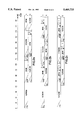
- FIG. 2 shows the operational sequence of the control system in three different cases where the filterability of the suspension and/or the condition of the filter is changed.
- FIG. 1 a filtration assembly in accordance with SE 8909267, where the suspension to be filtered is introduced at arrow C through line 2, which divides into two lines 2a and 2b leading to filter devices A and B, respectively.
- the suspension that is introduced is white liquor lime sludge.
- lines 2a and 2b are mounted valves 3a and 3b.
- Filtrate lines 4a and 4b with respective valves 5a and 5b run from the base of filters 1a and 1b, and the filtrate lines lead to the filtrate separator 6 for separation of filtrate, white liquor and the gas (air or air/vapor mixture) that follows with the white liquor to separator 6.
- the white liquor is emitted from separator 6 through outlet line 7 from the filtration assembly (arrow D), and the air is conducted from separator 6 via line 8 via a compressor 23 either through branch line 8a with valve 9a back to vessel A or through branch line 8b with valve 9b back to vessel B, to be used during the reset stage.
- a feed line 10 (arrow E) for the back-flushing medium, e.g., water, either to vessel A through branch line 10 with valve 11a or to vessel B through branch line 10b with valve 11b.
- the lime sludge that is removed during the reset stage is removed from the bottom of vessel A via valve 12a and from the bottom of vessel B via valve 12b, and this lime sludge is sent to a common tank provided for both vessels, e.g., a so-called lime sludge agitator.
- the lime sludge is drained with back-flushing fluid, and lime sludge diluted with back-flushing fluid is discharged from the filtration assembly through line 14 (arrow F).
- the illustrated filtration assembly also comprises drain lines 15a and 15b with valves 16a and 16b from each vessel, leading to a return line 17, which via pump tank 18 feeds into the white liquor's feed line 2.
- filtrate line 4a from a point prior to valve 5a, and return line 17 is extended a line 19a with valve 20a, and in the same manner there is provided a line 19b with valve 20b between filtrate line 4b and return line 17.
- a line 21a with valve 22a between filtrate line 4a from a point prior to valve 5a and tank 13 there is provided a line 21a with valve 22a, and likewise a line 21b with valve 22b.
- a line 25 is provided between gas line 8 from separator 6 and tank 13.
- valve 3b is closed and the white liquor lime sludge is introduced into vessel A through line 2a and the open valve 3a. This filling of the filter is shown farthest to the left in FIG. 2a and designated as "Fill".
- the filtrate valve 5a is kept closed while valve 20a is open. The purpose of this is to send the first filtered white liquor back to the incoming white liquor lime sludge, and this is done through lines 19a and 17.
- Valve 20a is then closed, and filtrate valves 5a and 36a are opened, Just prior to the closing of valve 20a, and are kept open during the entire course of filtration, designated as "Filtration" in FIG. 2a. All other valves in connection with vessel A are kept closed, i.e., valves 9a, 11a, 12a, 16a, 22a and 25a. During the actual filtration cycle, it is thus only valve 3a for the introduction of white liquor lime sludge, and valves 5a and 36a for the removal of the white liquor that are open.
- the filtration preferably takes place with the entire filter 1a disposed in the white liquor lime sludge, whereby the entire filter is used for the filtration, and the filtration proceeds until a suitable pressure difference is obtained across the filter element.
- this pressure difference is determined at least primarily by the pressure of the incoming white liquor lime sludge. It may, however, be determined at least to a certain degree by a vacuum within the filter, or a difference in the level between separator 6 and the filter.
- the white liquor is discharged, as described earlier, through line 7 from separator 6.
- pressure vessel A the filtration is concluded after attainment of the aforementioned suitable pressure difference, and vessel A will now be reset for a new filtration cycle.
- valve 3a is closed.
- valve 9a is opened and air/vapor mixture is fed from separator 6 via line 8 with compressor 23 and line 8b to the inside of the vessel to dry the deposited lime sludge on the filter mesh, whereupon it is further relieved of white liquor and thus also chemicals.
- valve 16a is opened to remove unfiltered white liquor lime sludge which is fed back via line 17 to the incoming white liquor lime sludge. This is indicated in FIG. 2a as “Drying”. After completion of the drying of the lime sludge layer, drain valve 16a is closed, followed immediately by closing of filtrate valve 5a and air valve 9a.
- Valve 11a is now opened for back-flushing of the lime-sludge layer, indicated as "Bf" in FIG. 2a, with back-flushing fluid, e.g., water from line 10, 10a in connection with the filter's filtrate ducts.
- back-flushing fluid e.g., water from line 10, 10a in connection with the filter's filtrate ducts.
- the back-flushing fluid is introduced such that the diluted lime sludge is caused to run down on its own into tank 19 through valve 12a, which is opened immediately after valve 11a has been opened.
- Valve 22a is then opened for a brief period for draining of the dilution fluid in the filter through line 21a down to tank 13. This is indicated as "E" (empty) in FIG. 2a.
- FIG. 2a An operational cycle corresponding to that described above for vessel A is also carried out in vessel B.
- the upper sector shows the operational sequence for vessel A, while the lower part of the figure shows the operational sequence for vessel B.
- the time indications at the top of FIG. 2 are included for purposes of illustration only, and should not be considered limiting factors for the invention.
- FIG. 2a thus shows a normal operational sequence (basic adjustment) for the two filters A and B.
- FIG. 2b is shown a corresponding operational sequence wherein the drying time is reduced substantially in relation to FIG. 2a.
- This reduction of the drying time may result from two causes: either that the filterability of the suspension being introduced has changed substantially, or that the condition of the filter mesh has changed.
- This change in the drying time is carried out by the control system itself if the pressure difference across the filter builds up too rapidly.
- FIG. 2c is shown a situation where the drying time has been reduced to a minimum value.
- the control system will make a check on the condition of the filter mesh after the drying (indicated as "T" (test) in FIG. 2c).
- T test
- This testing of the filter mesh is done by passing a fluid (e.g., water or air) into the filter and measuring the pressure difference across the filter mesh. If the pressure difference is higher than a certain predetermined value, the control system will be able to indicate whether it is time to replace the filter mesh.
- control system may also be used with other types of filtration devices. It should also be noted that the control system may be used to control more than two filters simultaneously.
Abstract
A method for controlling a filtration assembly wherein the amount of medium introduced into the filtration assembly is constant, even though the filterability of the medium or the condition of the filters has changed. The working cycle of the filtration assembly changes when the pressure difference across the filter mesh increases over a certain period of time. The control system is capable of distinguishing between the filterability of the medium introduced and the condition of the filter mesh.
Description
The present invention relates to a control system for a filtration assembly, and particularly a control system for the filtration assembly described in Swedish patent application no. 8903267 corresponding to PCT/SE90/00639.
With filtration according to the aforementioned applications, one uses a stationary filter disposed in a pressure vessel, wherein after completion of the filtration, a reset operation is carried out, comprising back-flushing of the filter before the start of the next filtration. The filtration takes place through at least one substantially vertically disposed filter element covered with a filter mesh surrounding at least one filter duct, through which flows the filtrate obtained during the filtration, e.g., white liquor or green liquor, while the filtered material, for example lime sludge (calcium carbonate) is deposited on the filter mesh. The pressure vessel is provided with at least one inlet for the suspension that is to be filtered, an outlet for the filtrate obtained, an outlet for the obtained material and an inlet for the medium for resetting the filter.
According to the prior art, in the utilization of a stationary filter during the lye treatment, the separation of white liquor and lime sludge is carried out in a so-called tube filter, i.e., downwardly suspended perforated tubes covered with filter mesh, where the filter outlet is directed upward. This tube filter is divided into discrete units having separate white liquor outlets from each section. While sections of the tube filter are being back-flushed, which is done with liquid that has already been filtered, i.e., white liquor, the filtration takes place in the other sections. This results in, inter alia, a low rate of utilization of the filter. In addition, during the entire process there is a continuous production of deposited material, i.e., lime sludge, from the back-flushing. This entails the disadvantage, among others, of the lime sludge having a high content of unfiltered liquid with a high content of chemicals.
Swedish patent application no. 7909774 describes a pressure filter and a method of filtration wherein the filtration time is altered as a result of the filterability of the suspension that is introduced. This means that one will have no indications of the condition of the filter.
By utilizing the present invention, it is possible for the amount of suspension being introduced to the filtration assembly to be kept constant and continuous, regardless of the suspension's filterability. In addition, the system will provide feedback on the condition of the filter and on the eventual need to replace one or more filter meshes.
This is achieved according to the invention with a control system that is characterized in that the working cycle of the filtration assembly is altered when the pressure difference across the filter mesh increases over a certain period of time, where the control system is capable of differentiating between the filterability of the medium introduced and the condition of the filter mesh. The filtration assembly comprises two or more filters, and the working cycle for all the filters is readjusted simultaneously. In the event of a change in the filterability of the medium introduced and/or the condition of the filter mesh, it is the reset time that is altered. If the reset time is reduced to a predetermined value, a fluid is passed through the filter mesh to determine the drop in pressure across the filter mesh.
Additional details and features of the invention will be apparent from the further description of a preferred embodiment form, with reference to the accompanying drawings.
FIG. 1 shows a filtration system having two pressure vessels to which the control system is specially adapted.
FIG. 2 shows the operational sequence of the control system in three different cases where the filterability of the suspension and/or the condition of the filter is changed.
In FIG. 1 is shown a filtration assembly in accordance with SE 8909267, where the suspension to be filtered is introduced at arrow C through line 2, which divides into two lines 2a and 2b leading to filter devices A and B, respectively. In the illustrated embodiment form of the filtration assembly in FIG. 1, the suspension that is introduced is white liquor lime sludge. On lines 2a and 2b are mounted valves 3a and 3b. Filtrate lines 4a and 4b with respective valves 5a and 5b run from the base of filters 1a and 1b, and the filtrate lines lead to the filtrate separator 6 for separation of filtrate, white liquor and the gas (air or air/vapor mixture) that follows with the white liquor to separator 6. The white liquor is emitted from separator 6 through outlet line 7 from the filtration assembly (arrow D), and the air is conducted from separator 6 via line 8 via a compressor 23 either through branch line 8a with valve 9a back to vessel A or through branch line 8b with valve 9b back to vessel B, to be used during the reset stage. For the reset stage there is provided a feed line 10 (arrow E) for the back-flushing medium, e.g., water, either to vessel A through branch line 10 with valve 11a or to vessel B through branch line 10b with valve 11b. The lime sludge that is removed during the reset stage is removed from the bottom of vessel A via valve 12a and from the bottom of vessel B via valve 12b, and this lime sludge is sent to a common tank provided for both vessels, e.g., a so-called lime sludge agitator. Preferably, prior to its removal from the pressure vessel, the lime sludge is drained with back-flushing fluid, and lime sludge diluted with back-flushing fluid is discharged from the filtration assembly through line 14 (arrow F). The illustrated filtration assembly also comprises drain lines 15a and 15b with valves 16a and 16b from each vessel, leading to a return line 17, which via pump tank 18 feeds into the white liquor's feed line 2. In addition, between filtrate line 4a, from a point prior to valve 5a, and return line 17, is extended a line 19a with valve 20a, and in the same manner there is provided a line 19b with valve 20b between filtrate line 4b and return line 17. Also, between filtrate line 4a from a point prior to valve 5a and tank 13 there is provided a line 21a with valve 22a, and likewise a line 21b with valve 22b. Further, a line 25 is provided between gas line 8 from separator 6 and tank 13. Between the air branch line 8a and the water branch line 10a at a point before valve 9a and after valve 11a, there is provided a line 24a with valve 25a; and in similar fashion there is provided line 24b with valve 25b between the air branch line 8b and water branch line 10b.
The purpose of the various lines and valves will now be described in more detail in connection with the functional description of a filtration cycle in pressure vessel A and a reset cycle in vessel B. The process is also illustrated schematically in FIG. 2a.
Before the filtration cycle begins, the previously deposited lime sludge is removed from vessel A, and the vessel is essentially drained of any white liquor lime sludge remaining from previous filtering processes. When the filtration begins, valve 3b is closed and the white liquor lime sludge is introduced into vessel A through line 2a and the open valve 3a. This filling of the filter is shown farthest to the left in FIG. 2a and designated as "Fill". During this brief introductory period, the filtrate valve 5a is kept closed while valve 20a is open. The purpose of this is to send the first filtered white liquor back to the incoming white liquor lime sludge, and this is done through lines 19a and 17. Valve 20a is then closed, and filtrate valves 5a and 36a are opened, Just prior to the closing of valve 20a, and are kept open during the entire course of filtration, designated as "Filtration" in FIG. 2a. All other valves in connection with vessel A are kept closed, i.e., valves 9a, 11a, 12a, 16a, 22a and 25a. During the actual filtration cycle, it is thus only valve 3a for the introduction of white liquor lime sludge, and valves 5a and 36a for the removal of the white liquor that are open. The filtration preferably takes place with the entire filter 1a disposed in the white liquor lime sludge, whereby the entire filter is used for the filtration, and the filtration proceeds until a suitable pressure difference is obtained across the filter element. Preferably, this pressure difference is determined at least primarily by the pressure of the incoming white liquor lime sludge. It may, however, be determined at least to a certain degree by a vacuum within the filter, or a difference in the level between separator 6 and the filter. The white liquor is discharged, as described earlier, through line 7 from separator 6. In pressure vessel A the filtration is concluded after attainment of the aforementioned suitable pressure difference, and vessel A will now be reset for a new filtration cycle. At the start of the reset cycle, valve 3a is closed. This is indicated in FIG. 2a as "Drain." Valve 9a is opened and air/vapor mixture is fed from separator 6 via line 8 with compressor 23 and line 8b to the inside of the vessel to dry the deposited lime sludge on the filter mesh, whereupon it is further relieved of white liquor and thus also chemicals. Immediately after valve 9a is opened, valve 16a is opened to remove unfiltered white liquor lime sludge which is fed back via line 17 to the incoming white liquor lime sludge. This is indicated in FIG. 2a as "Drying". After completion of the drying of the lime sludge layer, drain valve 16a is closed, followed immediately by closing of filtrate valve 5a and air valve 9a. Valve 11a is now opened for back-flushing of the lime-sludge layer, indicated as "Bf" in FIG. 2a, with back-flushing fluid, e.g., water from line 10, 10a in connection with the filter's filtrate ducts. Preferably the back-flushing fluid is introduced such that the diluted lime sludge is caused to run down on its own into tank 19 through valve 12a, which is opened immediately after valve 11a has been opened. Valve 22a is then opened for a brief period for draining of the dilution fluid in the filter through line 21a down to tank 13. This is indicated as "E" (empty) in FIG. 2a.
An operational cycle corresponding to that described above for vessel A is also carried out in vessel B. In FIG. 2a, the upper sector shows the operational sequence for vessel A, while the lower part of the figure shows the operational sequence for vessel B. The time indications at the top of FIG. 2 are included for purposes of illustration only, and should not be considered limiting factors for the invention.
FIG. 2a thus shows a normal operational sequence (basic adjustment) for the two filters A and B. In FIG. 2b is shown a corresponding operational sequence wherein the drying time is reduced substantially in relation to FIG. 2a. This reduction of the drying time may result from two causes: either that the filterability of the suspension being introduced has changed substantially, or that the condition of the filter mesh has changed. This change in the drying time is carried out by the control system itself if the pressure difference across the filter builds up too rapidly. By reducing the drying time and maintaining the filtration time, the capacity of the filtration assembly is not altered. In FIG. 2c is shown a situation where the drying time has been reduced to a minimum value. When this minimum value occurs, the control system will make a check on the condition of the filter mesh after the drying (indicated as "T" (test) in FIG. 2c). This testing of the filter mesh is done by passing a fluid (e.g., water or air) into the filter and measuring the pressure difference across the filter mesh. If the pressure difference is higher than a certain predetermined value, the control system will be able to indicate whether it is time to replace the filter mesh.
Although the utilization of the control system is described with reference to a specific filtration assembly, it is self-evident that the invention may also be used with other types of filtration devices. It should also be noted that the control system may be used to control more than two filters simultaneously.
Claims (6)
1. In a method for controlling a filtration assembly comprised of at least two filters, each filter having at least one filter element covered by a filter mesh with filtration taking place through said at least one filter element, and wherein the working cycle of the filtration assembly is altered when the pressure difference across at least one filter mesh exceeds a value, the improvement which comprises:
maintaining the flow rate of a medium introduced to the filtration assembly substantially constant, even after the filterability of said medium or the condition of the filters changes, said filtration assembly further comprising a control system capable of differentiating between the filterability of the medium introduced and the condition of the filter mesh of said at least one filter element, the differentiating being determined by said control system causing a different medium to pass through said assembly for testing the condition of each said filter mesh after an occurrence of said exceeding.
2. A method according to claim 1, further comprising simultaneously adjusting the working cycle for all the filters in response to an occurrence of at least one of said changes.
3. A method according to claim 1, further comprising carrying out a reset operation after said filtration by backflushing said at least one filter element, and altering the time of the reset operation as a result of at least one of a change in the filterability of the medium introduced and the condition of the filter mesh of said at least one element.
4. A method according to claim 3, further comprising testing the condition of each said filter mesh by passing a fluid through each said filter mesh to determine the pressure differential thereacross.
5. A method according to claim 4, wherein the fluid passed through each said filter mesh to determine the pressure differential thereacross is water or air.
6. A method according to claim 3, wherein each said filter mesh is backflushed with water.
Applications Claiming Priority (3)
| Application Number | Priority Date | Filing Date | Title |
|---|---|---|---|
| NO912312 | 1991-06-14 | ||
| NO912312A NO172882C (en) | 1991-06-14 | 1991-06-14 | PROCEDURE FOR REGULATING A FILTERING DEVICE |
| PCT/NO1992/000099 WO1992022374A1 (en) | 1991-06-14 | 1992-06-05 | Control system |
Publications (1)
| Publication Number | Publication Date |
|---|---|
| US5460733A true US5460733A (en) | 1995-10-24 |
Family
ID=19894217
Family Applications (1)
| Application Number | Title | Priority Date | Filing Date |
|---|---|---|---|
| US08/162,160 Expired - Lifetime US5460733A (en) | 1991-06-14 | 1992-06-05 | Control system distinguishing filterability of medium filtered |
Country Status (8)
| Country | Link |
|---|---|
| US (1) | US5460733A (en) |
| JP (1) | JPH07501741A (en) |
| AU (1) | AU2021692A (en) |
| CA (1) | CA2111224A1 (en) |
| FI (1) | FI109093B (en) |
| GB (1) | GB2272386A (en) |
| NO (1) | NO172882C (en) |
| WO (1) | WO1992022374A1 (en) |
Cited By (7)
| Publication number | Priority date | Publication date | Assignee | Title |
|---|---|---|---|---|
| US5766486A (en) * | 1995-07-27 | 1998-06-16 | Pall Corporation | Hybrid filter system and method for filtering process fluid |
| US5905197A (en) * | 1998-01-22 | 1999-05-18 | Hydranautics, Inc. | Membrane sampling device |
| US6499337B2 (en) * | 2000-02-17 | 2002-12-31 | Hoffman & Hoffman Electronic And Electro Mechanical Engineering Ltd. | Monitoring of particulate matter in water supply |
| US20110265893A1 (en) * | 2008-09-05 | 2011-11-03 | Simon Peter Scott | Filter assembly |
| CN105142826A (en) * | 2013-03-13 | 2015-12-09 | 联合工艺公司 | Uninteruppted filtering system for selective laser melting powder bed additive manufacturing process |
| US20190201817A1 (en) * | 2017-12-29 | 2019-07-04 | Enercorp Sand Solutions Inc. | Horizontal sand separator assembly |
| US10933620B2 (en) | 2014-11-21 | 2021-03-02 | Renishaw Plc | Additive manufacturing apparatus and methods |
Families Citing this family (2)
| Publication number | Priority date | Publication date | Assignee | Title |
|---|---|---|---|---|
| IT1256243B (en) * | 1992-12-23 | 1995-11-29 | PLANT FOR THE PURIFICATION AND FILTRATION OF WASTEWATER FROM MECHANICAL, CONVENTIONAL AND OTHER PROCESSES | |
| CN103990313B (en) * | 2014-06-06 | 2015-08-12 | 张家港保税区金品化工机械设备有限公司 | Low permeability oil field recovered water filtration system and backwash process thereof |
Citations (6)
| Publication number | Priority date | Publication date | Assignee | Title |
|---|---|---|---|---|
| US2572436A (en) * | 1945-04-12 | 1951-10-23 | Glenfield And Kennedy Ltd | Means for measuring and recording the filtrability of fluids |
| US3455146A (en) * | 1967-06-06 | 1969-07-15 | Du Pont | Method and apparatus for determining filtrability time |
| US4264445A (en) * | 1978-11-28 | 1981-04-28 | Enso-Gutzeit Osakeythio | Pressurized filter |
| US4482461A (en) * | 1982-12-20 | 1984-11-13 | French Systems, Inc. | Backwash control for constant volume-pressure filtration system |
| US5053141A (en) * | 1987-12-02 | 1991-10-01 | Laiho Kari U | Procedure and means for filtering, cleaning and homogenizing liquid substances using ultrasonics |
| US5149449A (en) * | 1989-10-04 | 1992-09-22 | Kent Strid | Method and device for filturing of suspensions |
Family Cites Families (4)
| Publication number | Priority date | Publication date | Assignee | Title |
|---|---|---|---|---|
| US4198298A (en) * | 1978-02-13 | 1980-04-15 | EDC/Enviro Development Co., Inc. | System and apparatus for control and optimization of filtration process |
| DE3116610C2 (en) * | 1981-04-27 | 1986-06-19 | Ruslan Ivanovič Batyrev | Method for controlling a filter system |
| GB2110553A (en) * | 1981-12-01 | 1983-06-22 | Willett And Company Limited Th | Pressurized filtration system |
| IL81713A (en) * | 1987-02-27 | 1992-03-29 | Filtration Water Filters For A | Method for filtering a fluid and filter system therefor |
-
1991
- 1991-06-14 NO NO912312A patent/NO172882C/en not_active IP Right Cessation
-
1992
- 1992-06-05 CA CA002111224A patent/CA2111224A1/en not_active Abandoned
- 1992-06-05 WO PCT/NO1992/000099 patent/WO1992022374A1/en active IP Right Grant
- 1992-06-05 AU AU20216/92A patent/AU2021692A/en not_active Abandoned
- 1992-06-05 JP JP5500715A patent/JPH07501741A/en active Pending
- 1992-06-05 US US08/162,160 patent/US5460733A/en not_active Expired - Lifetime
-
1993
- 1993-12-09 GB GB9325253A patent/GB2272386A/en not_active Withdrawn
- 1993-12-13 FI FI935589A patent/FI109093B/en active
Patent Citations (6)
| Publication number | Priority date | Publication date | Assignee | Title |
|---|---|---|---|---|
| US2572436A (en) * | 1945-04-12 | 1951-10-23 | Glenfield And Kennedy Ltd | Means for measuring and recording the filtrability of fluids |
| US3455146A (en) * | 1967-06-06 | 1969-07-15 | Du Pont | Method and apparatus for determining filtrability time |
| US4264445A (en) * | 1978-11-28 | 1981-04-28 | Enso-Gutzeit Osakeythio | Pressurized filter |
| US4482461A (en) * | 1982-12-20 | 1984-11-13 | French Systems, Inc. | Backwash control for constant volume-pressure filtration system |
| US5053141A (en) * | 1987-12-02 | 1991-10-01 | Laiho Kari U | Procedure and means for filtering, cleaning and homogenizing liquid substances using ultrasonics |
| US5149449A (en) * | 1989-10-04 | 1992-09-22 | Kent Strid | Method and device for filturing of suspensions |
Cited By (12)
| Publication number | Priority date | Publication date | Assignee | Title |
|---|---|---|---|---|
| US5766486A (en) * | 1995-07-27 | 1998-06-16 | Pall Corporation | Hybrid filter system and method for filtering process fluid |
| US5905197A (en) * | 1998-01-22 | 1999-05-18 | Hydranautics, Inc. | Membrane sampling device |
| US6499337B2 (en) * | 2000-02-17 | 2002-12-31 | Hoffman & Hoffman Electronic And Electro Mechanical Engineering Ltd. | Monitoring of particulate matter in water supply |
| US20110265893A1 (en) * | 2008-09-05 | 2011-11-03 | Simon Peter Scott | Filter assembly |
| US8794263B2 (en) * | 2008-09-05 | 2014-08-05 | Mtt Technologies Limited | Filter assembly |
| US10974184B2 (en) | 2008-09-05 | 2021-04-13 | Renishaw Plc | Filter assembly |
| CN105142826A (en) * | 2013-03-13 | 2015-12-09 | 联合工艺公司 | Uninteruppted filtering system for selective laser melting powder bed additive manufacturing process |
| CN105142826B (en) * | 2013-03-13 | 2018-01-30 | 联合工艺公司 | Uninterrupted filtration system for selective laser melting powder bed increment manufacturing process |
| US10265772B2 (en) | 2013-03-13 | 2019-04-23 | United Technologies Corporation | Uninteruppted filtering system for selective laser melting powder bed additive manufacturing process |
| US10933620B2 (en) | 2014-11-21 | 2021-03-02 | Renishaw Plc | Additive manufacturing apparatus and methods |
| US20190201817A1 (en) * | 2017-12-29 | 2019-07-04 | Enercorp Sand Solutions Inc. | Horizontal sand separator assembly |
| US11679348B2 (en) * | 2017-12-29 | 2023-06-20 | Enercorp Engineered Solutions Inc. | Horizontal sand separator assembly |
Also Published As
| Publication number | Publication date |
|---|---|
| WO1992022374A1 (en) | 1992-12-23 |
| GB9325253D0 (en) | 1994-03-09 |
| NO172882C (en) | 1993-09-22 |
| JPH07501741A (en) | 1995-02-23 |
| NO172882B (en) | 1993-06-14 |
| FI935589A0 (en) | 1993-12-13 |
| AU2021692A (en) | 1993-01-12 |
| GB2272386A (en) | 1994-05-18 |
| FI109093B (en) | 2002-05-31 |
| FI935589A (en) | 1994-02-11 |
| NO912312D0 (en) | 1991-06-14 |
| NO912312L (en) | 1992-12-15 |
| CA2111224A1 (en) | 1992-12-23 |
Similar Documents
| Publication | Publication Date | Title |
|---|---|---|
| AU637417B2 (en) | Method and device for filtering of suspensions | |
| CA1282345C (en) | Variable volume filter or concentrator | |
| CA1159770A (en) | Filter | |
| EP0344633B1 (en) | Column filter using bundles of long fibers | |
| CA1268427A (en) | Filter for continuous filtering of a suspension under pressure | |
| US5460733A (en) | Control system distinguishing filterability of medium filtered | |
| US2562730A (en) | Filter tube | |
| CN105879441B (en) | A kind of integrated filtering water cleaning systems based on modularization separation assembly | |
| US2723761A (en) | Method and device for the purification or preparation of liquids | |
| US3428177A (en) | Fluid control means for filter backwashing and air scouring | |
| CA1242979A (en) | Pressure filter (hpc clarifil) | |
| US3436260A (en) | Method for cleaning filter bed for sugar liquor | |
| US2952363A (en) | Batch feeding apparatus and systems | |
| US4388197A (en) | Procedure for separating finely divided matter from a suspension by filtering | |
| CA1205754A (en) | Method of and filter thickener for thickening of suspensions | |
| NO309230B1 (en) | Device for controlling the addition of a chemical dewatering modifier in a flowing suspension, device for flocculating a suspension and dewatering the flocculated suspension, and a method for dewatering a suspension | |
| US5160442A (en) | Method of cleaning a disposable cartridge filter | |
| CN207957966U (en) | A kind of used filter of infant industry water process | |
| RU2160146C2 (en) | Device for removal of filtrate from vacuum filter | |
| RU2034622C1 (en) | Method for automatic controlling of separation of organic liquid emulsions with liquid phase | |
| WO2001081675A1 (en) | A process and an apparatus for forming a web | |
| JPH09206061A (en) | Process for controlling operation of beer filtration apparatus | |
| RU1833842C (en) | Way for regulation of medium-concentrated fiber suspension discharge and device for its embodiment | |
| CS200501B2 (en) | Process for the filtration of liquids containing fine sludge especially juices of sugar industry | |
| DE2344064A1 (en) | Filter cleaning system - partic. for porous or sieve type filter aid-coated filter elements |
Legal Events
| Date | Code | Title | Description |
|---|---|---|---|
| AS | Assignment |
Owner name: CAUSTEC AB, SWEDEN Free format text: ASSIGNMENT OF ASSIGNORS INTEREST;ASSIGNORS:RASMUSSEN, SIGMUND;HORLYK, LARS;OSWALDSSON, ROLF;AND OTHERS;REEL/FRAME:007052/0707 Effective date: 19931215 |
|
| STCF | Information on status: patent grant |
Free format text: PATENTED CASE |
|
| FEPP | Fee payment procedure |
Free format text: PAYOR NUMBER ASSIGNED (ORIGINAL EVENT CODE: ASPN); ENTITY STATUS OF PATENT OWNER: LARGE ENTITY |
|
| FPAY | Fee payment |
Year of fee payment: 4 |
|
| FPAY | Fee payment |
Year of fee payment: 8 |
|
| FPAY | Fee payment |
Year of fee payment: 12 |