US5465854A - Telescoping tube assembly - Google Patents
Telescoping tube assembly Download PDFInfo
- Publication number
- US5465854A US5465854A US08/426,634 US42663495A US5465854A US 5465854 A US5465854 A US 5465854A US 42663495 A US42663495 A US 42663495A US 5465854 A US5465854 A US 5465854A
- Authority
- US
- United States
- Prior art keywords
- longitudinal
- tube section
- telescoping
- section
- rigid support
- Prior art date
- Legal status (The legal status is an assumption and is not a legal conclusion. Google has not performed a legal analysis and makes no representation as to the accuracy of the status listed.)
- Expired - Lifetime
Links
Images


Classifications
-
- B—PERFORMING OPERATIONS; TRANSPORTING
- B66—HOISTING; LIFTING; HAULING
- B66C—CRANES; LOAD-ENGAGING ELEMENTS OR DEVICES FOR CRANES, CAPSTANS, WINCHES, OR TACKLES
- B66C17/00—Overhead travelling cranes comprising one or more substantially horizontal girders the ends of which are directly supported by wheels or rollers running on tracks carried by spaced supports
Definitions
- This invention relates to telescoping tubes, and more particularly to longitudinally extensible and retractable telescoping tubes which extend and retract in a vertical direction for inspection testing of large stationary objects.
- these telescoping crane booms involve lifting substantial weights or loads which cause very large bending moments on the crane boom.
- These crane boom bending moments and forces are offset typically by increasing the boom rigidity and strength through increasing the width of each boom section. This increase in width adds excessive weight in an attempt to combat the moment created about its base.
- various alternatives such as thicker flat bottom plates and thinner surrounding channels have been used in attempts to lighten the weight while increasing the strength.
- vertically telescoping devices which are similar in appearance to the crane booms involve considerably different design considerations. Instead of being concerned about compressive loads on a lower section versus tension loads on a top section as well as the bending moment about its base as in the crane booms, vertically telescoping tubes, operating generally in the same direction as gravity, are more concerned about accurate movement, higher rigidity, higher dampening, low-cost construction, and linear load capability.
- British Patent No. 970,441 discloses a power manipulator which vertically positions itself by extending a column assembly comprising a number of telescoping sections adapted to rest one within another. This patent further teaches that control of position is important thus the vertical movement should be as smooth as possible.
- the British patent discloses a column comprising an assembly of three telescopic tubes which rest one within another and are stowed within a carriage. Three pairs of rollers are carried on the inner surface of a cylindrical shroud at the base of the carriage and these three pairs of rollers cooperate with three equally spaced vertical guides on the outermost tube. The middle and inner tube are similarly guided.
- the invention relates to vertically extensible telescoping tubes.
- the telescoping tube is suspended from a frame and extends and retracts in a vertically manner so that a test device can be properly positioned to inspect large stationary objects for structural integrity.
- the vertically telescoping tube is horizontally movable about the frame for the purpose of properly positioning the test device in reference to the large stationary object and for moving the test device about the outer perimeter of the larger stationary object during testing.
- the vertically extensible telescoping tube assembly has a frame supporting an elevated mounting platform off of which the vertically telescoping tube operates.
- the telescoping tube extends vertically from the mounting platform along a reference axis perpendicular to the mounting platform.
- the telescoping extensible tubes consists of a fixed longitudinal tube section attached to the mounting platform where a second longitudinal section telescopes relative to the fixed longitudinal tube section.
- Each longitudinal tube section is a rigid support plate with a U-shaped housing having two spaced apart longitudinal edges which attach to the rigid ,support plate.
- each longitudinal section Between each longitudinal section are bearings or wheels which allow for the telescopic movement.
- the bearings or wheels are positioned to make contact only with the rigid support plates for purposes of guiding the longitudinal tubes.
- bulging of the U-shaped housings, which contributes to deflection of each tube section is eliminated.
- the contacting portions of the bearings or wheels are positioned proximate each other and if possible overlap so that substantially all of the forces are transferred through the rigid support plates of the moveable tube sections to the rigid support plate of the fixed housing.
- the vertically extensible telescoping tube includes five sections of equivalent length but of decreasing width and depth such that each succeeding section may retract and nest in the preceding section.
- the telescoping action is produced by rotation of four drum systems of effective differing diameter, wherein each drum has a drive cable wrap therearound with each drive cable being attached to a different longitudinal section.
- a flexible conduit is connected at one end to a conduit housing mounted on the outside of the fixed longitudinal tube section and at the other end of the conduit to one of the telescoping longitudinal sections at least once removed from the fixed longitudinal section such that the flexible conduit forms at least one loop that extends and retracts with the telescoping tube.
- This flexible conduit protects wires, cables or the like from binding up the telescoping system or being kinked or severed.
- FIG. 1 is a perspective view of a telescoping tube of the present invention mounted to an elevated frame;
- FIG. 2 is a schematic view of the interior of the telescoping tube
- FIG. 3 is an end view of the telescoping tube taken along line 3--3 in FIG. 2 with parts broken away;
- FIG. 4 is a sectional view of one set of stops
- FIG. 5 is an end view of a second embodiment of the telescoping tube of the present invention with parts broken away;
- FIG. 6 is a plan view of a drive mechanism for the telescoping tube.
- FIG. 1 Illustrated generally in FIG. 1 at 10 is a longitudinally extensible and retractable telescoping tube of the present invention.
- the telescoping tube 10 is attached to a frame 12 on an elevated mounting platform 14.
- the telescoping tube 10 extends and retracts in a longitudinally vertical direction from the mounting platform 14 along a reference axis 15 allowing a test device 16 mounted on a remote end thereof to inspect a large stationary object such as a tank 18.
- the construction of the telescoping tube 10, described in detail below, provides a compact rigid structure so that high accuracy is maintained with respect to the reference axis 15. Therefore, the precise location of the test device 16 can be determined easily.
- the frame 12 is a shell-like structure with four support legs 20 and various cross-supports 22.
- first horizontal slide tracks 24 are two perpendicular sets of parallel slide tracks referred to as first horizontal slide tracks 24 and second horizontal slide tracks 26.
- the two sets of horizontal slide tracks 24 and 26 allow horizontal movement of the mounting platform 14 in a plane perpendicular to the reference axis 15.
- the first horizontal slide tracks 24 fixedly attach to the cross support 21 guide the second set of horizontal slide tracks 26 in movement along the cross supports 21 using a conventional drive mechanism, not shown.
- the mounting platform 14 is movable upon the second horizontal slide tracks. Movement of the platform 14 in this plane positions the telescoping tube 10 and accompanying reference axis 15 about the large stationary object 18. When combined with telescoping movement of the tube 10 along the reference axis 15 complete inspection of its outside surface is possible.
- the telescoping tube 10 is made up of five longitudinal tube sections 28, 30A, 30B, 30C and 30D illustrated schematically in more detail in FIG. 2. It is to be understood that the number of sections may be increased or decreased without altering the objective or performance of the invention.
- the uppermost longitudinal tube section 28 is fixed to the mounting platform 14.
- Each of the four succeeding tube 30A-30D sections is vertically movable such that each extends and retracts from within the preceding larger section in a telescoping manner.
- first telescoping tube section 30A extends and retracts from within the fixed longitudinal section 28; the second telescoping longitudinal tube section 30B extends and retracts from within the first longitudinal tube section 30A; the third telescoping longitudinal tube section 30C extends and retracts from within the second longitudinal tube section 30B; and the fourth telescoping longitudinal tube section 30D extends and retracts from within the third longitudinal tube section 30C.
- the four telescoping sections 30A-30D are fully retracted wherein the four telescoping sections 30A-30D nest within the fixed section 28.
- each telescoping section is overlapped by the section preceding it thereby allowing transfer of the forces through the support plates.
- FIG. 3 illustrates that each of the sections 28 and 30A-30D include a relatively thin U or similar shaped housing 34A, 34B, 34C, 34D and 34E joined to a thicker support plate 32A, 32B, 32C, 32D and 32E along a pair of longitudinal edges 36A, 36B, 36C, 36D and 36E, respectively.
- the thicker support plates 32A-32E although sufficiently rigid for compressive loading, are inherently weak to torsion bending.
- the attachment of the thin housings 34A-34E to each respective thick support plate 32A-32E produces a higher rigidity structure by providing a load path for shear loads.
- the housings 34A-34E are bolted to each respective thicker support plate 32A-32E as desired.
- the replaceable construction allows the user, if he chooses, to construct the thin housing 34A-34E from, for example, a lighter material such as aluminum or a composite material to suit various applications.
- This concept of the thin housing 34 being made of a different material results in improved strength to weight ratios which results in improved natural frequency and thus increased damping.
- Replacability of the housings 34A-34E also aids in repair in the event one of the tube sections were to be damaged. In this manner only the damaged part need be replaced rather than the whole tube section.
- a layer of ISD-110 damping material 31A, 31B, 31C, 31D and 31E such as Polymer Constraining Layered Damping Material, manufactured by 3M Company, St. Paul, Minn., is applied to an inside surface 33A, 33B, 33C, 33D and 33E of each support plate 32A-32E.
- Location of the damping material on the inside surfaces 33A-33E is preferred since the neutral axis of each tube section is proximate on this surface due to greater mass of the support plates 32A-32E relative to the housings 34A-34E.
- two parallel linear bearing tracks 42A, 42B, 42C and 42D are connected to the thick support plates 32B-32E on each of the sections.
- the sets of linear bearing tracks 42A-42D are attached to the opposite side of the thick support plate 32A-32D as the thin housing 34A-34E, while sets of linear bearings 44A, 44B, 44C and 44D engage the tracks 42A-42D in a conventional manner to maintain the position of each support plate 32A-32E, and the tube sections 28 and 30A-30D relative to each other and parallel to the reference axis 15.
- Each telescoping section 30A-30D has one set of four linear roller 10 bearings, where a sequential-pair of linear roller bearings engages each of the two parallel bearing tracks 42A-42D.
- the sets of bearings 44A-44D are mounted to the rigid support plates 32A-32E in overlapping placement so that force loads can be transferred directly through the support plates 32A-32D to the fixed tube section 28.
- the linear bearings thus concentrate the aligning forces between the support plates 32A-32E to a common selected portion of each plate that being proximate the longitudinal edges of the support plates 32A-32E.
- FIG. 5 illustrates a second embodiment wherein linear bearings 44 and bearing tracks 42 have been replaced by C-brackets 48A, 48B, 48C and 48D each C-bracket having a set of three wheels 50A, 50B, 50C and 50D or multi-directional bearings situated therein.
- the thick support plates 32A-32E are guided relative to each other on the lateral edges 36A-36E of each of the thick support plates 32A-32E.
- the thin housing 34A-34E is bolted about its edges to the thick support plate 32A-32E at a position in from the lateral edges 36A-36E of the thick support plate 32A-32E so the C-brackets 48A-48D can be positioned about these lateral edges 36A-36E to allow the succeeding longitudinal section to extend and retract.
- four C-brackets 48A-48D (similar to the linear bearings 44A-44D) with two about each lateral edge 36A-36D of each of the thick support plates 32B-32E allow retraction and extension of the succeeding longitudinal section.
- forces are transferred only through the support plates.
- the C-brackets are positioned about the longitudinal sides of the support plates to concentrate transfer of forces along the edges.
- the tracks 42A-42D and bearings 44A-44D, and the C-brackets 48A-48D and wheels 50A-50D are attached only to the thick and rigid support plates 32A-32E. This results in the forces being displaced between the sections 28 and 30A-30D only through the rigid support plates 32A-32E, where each rigid support plate 32A-32E is strengthened by a U-shaped housing 34A-34E.
- a central aperture 58 is formed by the five hollow longitudinal apertures 38 being aligned.
- the longitudinal tube sections 28 and 30A-30D which are held together by the interaction between the linear bearings 44A-44D and the bearing tracks 42A-42D, or in the alternative the C-brackets 48A-48D and the wheels 50A-50D, have drive cables 60A, 60B, 60C and 60D attached thereto and running through the central aperture 58.
- the drive cables 60A-60D connect to a drive mechanism 61 (FIG. 1 ) located on the mounting platform 14, which controls the amount of extension and retraction of that corresponding tube section.
- the drive cables 60B-60D are connected to the thick support plates 32B-32D with fasteners 62 attached to an end of each of the drive cables. Each of the fasteners 62 is bolted to the corresponding support plate 32B-32D.
- the drive cable 60A is connected to the thick support plate 32A with a pulley 78, which will be discussed later.
- a controller signals to a drum reel system 66 to take in or release out the drive cables 60A-60D thereby controlling the extension and retraction of the telescoping tube 10 as a whole.
- the reel system 66 which is attached to the mounting plate 14, is comprised of spools or drums 76A, 76B, 76C and 76D which are rotated to take in or let out the drive cables 60A-60D as desired through instructions from the controller 64.
- the telescoping sections 30A-30D are extended and retracted for positioning inspection test devices 16.
- Each of the four telescoping sections extends in equal increments thereby exposing the same length of section as is exposed by the other three telescoping sections.
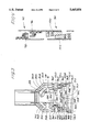
- the reel system 66 in more detail includes a motor 68 which drives a gear box 70. Inside this gear box 70 is a driving mechanism causing the motor 68 to drive two axles 72 and 74 at the same rotational speed. Two spools or drums are attached to each of the two axles such that four total drums exist. On the first axle 72 is the first drum 76A and the second drum 76B, while on the second axle 74 is the third drum 76C and the fourth drum 76D.
- the first drive cable 60A wraps about the first drum 76A and is connected at its other end to the first telescoping tube section 30A which is the section nearest the fixed tube section 28.
- the second drive cable 60B wraps about the second drum 76B and is connected at its other end to the second telescoping tube section 30B.
- Both the first drum 76A and the second drum 76B have the same diameter. However, as stated above, it is preferred that all of the tube sections move equal distances during movement of the telescoping tube 10. Therefore, the second telescoping tube section 30B must move at twice the speed as the first telescoping tube section 30A. A pulley 78 is used to accomplish this desired result.
- the first drive cable 60A operates about the pulley 78 and continues such that it re-connects to the mounting platform 14 instead of directly to the first telescoping section 30A.
- the pulley 78 is attached to this first telescoping tube section 30A and therefor the first telescoping tube section 30A moves at half the speed as the second telescoping tube section 30B when the same amount of cable is released from the same size drum attached to the same axle 72.
- the second drum 76B could be designed to be twice the diameter of the first drum 76A thereby allowing twice as much length of the second drive cable 60B to extend or retract as the first drive cable 60A when the first axle 72 is rotated. This would result in elimination of the need for the pulley 78.
- the third drum 76C and the fourth drum 76D On the second axle 74 is the third drum 76C and the fourth drum 76D.
- the third drive cable 60C wraps about the third drum 76C and is connected at its other end to the third telescoping section 30C.
- the fourth drive cable 60D wraps about the fourth drum 76D and is connected at its other end to the fourth telescoping section 30D.
- the third drum 76C is of smaller diameter than the fourth drum 76D such that the fourth telescoping section 30D telescopes at a faster rate than the preceding sections such that the exposed portion 80 of each of the telescoping sections 30 remains of equal length during extension and retraction of the telescoping tube 10.
- the ratios of the differences in diameter of each of the drums 76A-76D so that each telescoping section 30 will extend and retract in equal increments is as follows.
- the second telescoping section 30B must move twice the distance in comparison to the first telescoping section 30A so that the second drum 76B should be twice as large as the first drum 76A; however, the first and second drums 76A and 76B are of the same diameter because of use of the pulley 78 thereby causing the first telescoping section 30A to move at half the rate of the second telescoping section 30B.
- the third telescoping section 30C must move one and a half times faster than the second telescoping section 30B so that the third drum 76C is one and a half times larger than the second drum 76B.
- the fourth telescoping section 30D must move one and one third times faster than the third telescoping section 30C so that the fourth drum 76D is one and one-third times larger than the third drum 76C.
- the drum reel system includes a motor which drives a gear box where inside this gear box are differential gearing means such that the motor drives the two axles through the gear box at different speeds. This allows the size ratio of the first and second drums versus the third and fourth drums to be correspondingly altered based upon the change in axle speed.
- a flexible conduit 82 Running through the flexible conduit 82 are wires (not shown) for measurement, control and the like, where the wires can be electric wires, fiber optic cables, pneumatic tubes, and the like.
- the measurement and control wires are connected to data receiving devices (not shown) on the mounting platform 14 and frame 12.
- the flexible conduit 82 is mounted to the telescoping tube 10 at a first attachment point 84A in a conduit housing 86 attached to the outside of the fixed section 28.
- the flexible conduit 82 is fastened to the housing 86 so that when the telescoping sections 30 are extended and retracted the measurement and control wires do not tangle but instead they curl upward and downward within the flexible conduit 82 at a first curve 88A as required by the telescoping action.
- the first curve 88A moves within the housing 86 since the flexible conduit 82 is not attached to the fixed section 28 or the first telescoping section 30A except for at the first attachment point 84A.
- the flexible conduit 82 curls at a second curve 88B and extends through a passage 90 into the hollow longitudinal aperture 38 between the second 30B and third 30C telescoping tube sections where it is fastened at a second attachment point 84B which is on the third telescoping tube section 30C.
- the flexible conduit 82 faces an upward direction so that when the telescoping sections 30 are extended and retracted the measurement and control wires do not tangle but instead move upward or downward based upon the movement of a third curve 88C of the flexible conduit 82.
- the third curve 88C moves since the flexible conduit 82 is not attached to any of the longitudinal sections 30A-30C about the central apertures 58 except to the fourth telescoping tube section 30D.
- the flexible conduit 82 is fastened in a downward direction on the fourth telescoping section 30D at a third attachment point 84C whereat signal leads or the like connects in a conventional manner to the inspection test device 16.
- each telescoping section 30A-30D contains an upper stop 92 and a lower stop 94.
- the upper stop 92 functions perpendicular to the motion of the longitudinal section such that the tube section is blocked from further upward motion.
- Each upper stop 92 includes an outwardly extending block 96 on each of the telescoping sections 30 which comes into contact with an inwardly extending block 98 on the section that precedes the one with the outwardly extending block 96.
- the lower stop 94 increasingly absorbs energy under increased friction until further motion is restrained when an outwardly extending brake or wedge 100 on a telescoping section comes into contact with an inwardly extending brake or wedge 102.
- the outwardly extending wedge 100 is of decreasing dimension from top to bottom while the inwardly extending wedge 102 is of increasing dimension from top to bottom such that when in contact they will interact to cease relative motion between the corresponding reactions.
- an extensible and retractable telescoping tube positions test devices that inspect large stationary objects.
- the tube has three dimensional adjustment capabilities and is vertically suspended from a frame.
- Each tube sections comprises a U-shaped housing secured to a thicker support plate.
- Drive cables attached at one end to a tube section and at the other end to a drive mechanism cause the telescoping movement.
- Guide mechanisms such as linear bearings and corresponding tracks, or a C-bracket and wheel combination, mounted to each of the thicker support plates guide the plates parallel to a reference axis with improved accuracy and with structural rigidity so that the positions of the remote end of the telescoping tube is precisely known, thereby improving the testing results of the test device attached to the end of the extensible and retractable telescoping tube.
Abstract
Description
Claims (23)
Priority Applications (1)
| Application Number | Priority Date | Filing Date | Title |
|---|---|---|---|
| US08/426,634 US5465854A (en) | 1993-07-30 | 1995-04-21 | Telescoping tube assembly |
Applications Claiming Priority (2)
| Application Number | Priority Date | Filing Date | Title |
|---|---|---|---|
| US10091193A | 1993-07-30 | 1993-07-30 | |
| US08/426,634 US5465854A (en) | 1993-07-30 | 1995-04-21 | Telescoping tube assembly |
Related Parent Applications (1)
| Application Number | Title | Priority Date | Filing Date |
|---|---|---|---|
| US10091193A Continuation | 1993-07-30 | 1993-07-30 |
Publications (1)
| Publication Number | Publication Date |
|---|---|
| US5465854A true US5465854A (en) | 1995-11-14 |
Family
ID=22282164
Family Applications (1)
| Application Number | Title | Priority Date | Filing Date |
|---|---|---|---|
| US08/426,634 Expired - Lifetime US5465854A (en) | 1993-07-30 | 1995-04-21 | Telescoping tube assembly |
Country Status (3)
| Country | Link |
|---|---|
| US (1) | US5465854A (en) |
| JP (1) | JP3404399B2 (en) |
| WO (1) | WO1995003991A1 (en) |
Cited By (15)
| Publication number | Priority date | Publication date | Assignee | Title |
|---|---|---|---|---|
| US5624047A (en) * | 1995-04-24 | 1997-04-29 | General Electric Company | Telescoping mast with zero clearance for refueling machine |
| US5762467A (en) * | 1996-04-26 | 1998-06-09 | Par Systems, Inc. | Underground storage tank manipulator |
| US6062404A (en) * | 1996-12-20 | 2000-05-16 | Grove U.S. L.L.C. | Device and method for arresting sections of a telescopic jib |
| WO2002002453A2 (en) * | 2000-06-30 | 2002-01-10 | Par Systems, Inc. | Segmented support structure and method and fixture for making the same |
| US6499612B1 (en) | 2001-07-27 | 2002-12-31 | Link-Belt Construction Equipment Co., L.P., Lllp | Telescoping boom assembly with rounded profile sections and interchangeable wear pads |
| US6561368B1 (en) | 2000-05-01 | 2003-05-13 | Par Systems, Inc. | Telescoping tube assembly with a cabling system |
| US20060042131A1 (en) * | 2004-08-30 | 2006-03-02 | Caterpillar Inc. | Wear pad for an extendable linkage |
| US20080031716A1 (en) * | 2006-08-02 | 2008-02-07 | Par Systems, Inc. | Manipulator mast system with support brace |
| FR2921578A1 (en) * | 2007-09-28 | 2009-04-03 | Sidel Participations | MANIPULATOR ROBOT FOR PALLETIZER |
| US7624967B1 (en) | 2006-04-19 | 2009-12-01 | Par Systems, Inc. | Opposed-rope hoist driven telescoping mast |
| EP2138983A2 (en) | 2008-06-26 | 2009-12-30 | Steven Michael Faes | Article storage and retrieval apparatus and vending machine |
| US8550267B2 (en) | 2010-12-16 | 2013-10-08 | Korea Atomic Energy Research Institute | Apparatus for cable management synchronized with telescopic motion |
| US9126764B1 (en) | 2013-03-19 | 2015-09-08 | Cbw Automation, Inc. | Telescoping article retrieval system with plenum assembly attached to slave belt |
| US10794079B2 (en) | 2016-02-24 | 2020-10-06 | Terex Usa, Llc | System and method for installing a cross arm on a utility pole |
| CN113203679A (en) * | 2021-04-21 | 2021-08-03 | 重庆中岛工程建设管理有限公司 | Manage and use waterproofing membrane hollowing detection device |
Citations (21)
| Publication number | Priority date | Publication date | Assignee | Title |
|---|---|---|---|---|
| GB970441A (en) * | 1962-08-02 | 1964-09-23 | Gen Electric Co Ltd | Improvements in or relating to power manipulators |
| US3214033A (en) * | 1962-07-05 | 1965-10-26 | Hydrauliska Ind Aktiebolaget | Hydraulic line configuration for extensible members |
| US3247978A (en) * | 1962-12-12 | 1966-04-26 | Programmed & Remote Syst Corp | Manipulator hand |
| US3481490A (en) * | 1966-06-30 | 1969-12-02 | Gottwald Kg Leo | Telescopic jib for jib cranes |
| US3708937A (en) * | 1970-09-28 | 1973-01-09 | Kidde & Co Walter | Trapezoidal telescoping crane boom |
| US3736710A (en) * | 1970-12-03 | 1973-06-05 | Kidde & Co Walter | Four-section fully hydraulically operated crane boom having three individually supported single piston rams contained within fly section |
| US3837502A (en) * | 1973-03-12 | 1974-09-24 | Bucyrus Erie Co | Light weight boom construction |
| US3840128A (en) * | 1973-07-09 | 1974-10-08 | N Swoboda | Racking arm for pipe sections, drill collars, riser pipe, and the like used in well drilling operations |
| US3985234A (en) * | 1973-12-20 | 1976-10-12 | Creusot-Loire | Telescopic boom for a crane |
| FR2307756A1 (en) * | 1975-04-16 | 1976-11-12 | Fulton Industries | LIFTING GEAR BOOM, WITH TELESCOPIC ELEMENTS IN PLATES AND U-PROFILES |
| US4016688A (en) * | 1975-05-27 | 1977-04-12 | Fmc Corporation | Extensible crane boom structure |
| US4171597A (en) * | 1976-01-29 | 1979-10-23 | Coles Cranes Limited | Crane boom and telescopic section for it |
| US4327533A (en) * | 1980-08-13 | 1982-05-04 | Kidde, Inc. | Crane boom extending, retracting and cooperative latching arrangement |
| SU1025659A1 (en) * | 1981-09-25 | 1983-06-30 | Всесоюзный научно-исследовательский институт строительного и дорожного машиностроения | Telescopic boom |
| GB2128957A (en) * | 1982-10-27 | 1984-05-10 | Fuchs Johannes | A boom, for example for lifting apparatus, a platform hoist, or a dredger |
| US4459786A (en) * | 1981-10-27 | 1984-07-17 | Ro Corporation | Longitudinally bowed transversely polygonal boom for cranes and the like |
| US4534006A (en) * | 1981-05-15 | 1985-08-06 | D.E.A. Digital Electronic Automation S.P.A. | Operating arm unit controlled by a computer system |
| US4547119A (en) * | 1981-10-23 | 1985-10-15 | United States Robots, Inc. | Robotic manipulator arm |
| US4782713A (en) * | 1985-09-10 | 1988-11-08 | Fanuc Ltd | Industrial robot shaft supporting mechanism |
| FR2642059A1 (en) * | 1988-12-29 | 1990-07-27 | Ipr Productique Sarl | Translation control device, particularly for a handling assembly |
| US5314083A (en) * | 1985-08-13 | 1994-05-24 | Mannesmann Ag | Telescopic tower |
-
1994
- 1994-07-26 WO PCT/US1994/008441 patent/WO1995003991A1/en active Search and Examination
- 1994-07-26 JP JP50592695A patent/JP3404399B2/en not_active Expired - Lifetime
-
1995
- 1995-04-21 US US08/426,634 patent/US5465854A/en not_active Expired - Lifetime
Patent Citations (22)
| Publication number | Priority date | Publication date | Assignee | Title |
|---|---|---|---|---|
| US3214033A (en) * | 1962-07-05 | 1965-10-26 | Hydrauliska Ind Aktiebolaget | Hydraulic line configuration for extensible members |
| GB970441A (en) * | 1962-08-02 | 1964-09-23 | Gen Electric Co Ltd | Improvements in or relating to power manipulators |
| US3247978A (en) * | 1962-12-12 | 1966-04-26 | Programmed & Remote Syst Corp | Manipulator hand |
| US3481490A (en) * | 1966-06-30 | 1969-12-02 | Gottwald Kg Leo | Telescopic jib for jib cranes |
| US3708937A (en) * | 1970-09-28 | 1973-01-09 | Kidde & Co Walter | Trapezoidal telescoping crane boom |
| US3736710A (en) * | 1970-12-03 | 1973-06-05 | Kidde & Co Walter | Four-section fully hydraulically operated crane boom having three individually supported single piston rams contained within fly section |
| US3837502A (en) * | 1973-03-12 | 1974-09-24 | Bucyrus Erie Co | Light weight boom construction |
| US3840128A (en) * | 1973-07-09 | 1974-10-08 | N Swoboda | Racking arm for pipe sections, drill collars, riser pipe, and the like used in well drilling operations |
| US3985234A (en) * | 1973-12-20 | 1976-10-12 | Creusot-Loire | Telescopic boom for a crane |
| US4004695A (en) * | 1975-04-16 | 1977-01-25 | Fulton Industries, Inc. | Channel and plate telescopic crane boom |
| FR2307756A1 (en) * | 1975-04-16 | 1976-11-12 | Fulton Industries | LIFTING GEAR BOOM, WITH TELESCOPIC ELEMENTS IN PLATES AND U-PROFILES |
| US4016688A (en) * | 1975-05-27 | 1977-04-12 | Fmc Corporation | Extensible crane boom structure |
| US4171597A (en) * | 1976-01-29 | 1979-10-23 | Coles Cranes Limited | Crane boom and telescopic section for it |
| US4327533A (en) * | 1980-08-13 | 1982-05-04 | Kidde, Inc. | Crane boom extending, retracting and cooperative latching arrangement |
| US4534006A (en) * | 1981-05-15 | 1985-08-06 | D.E.A. Digital Electronic Automation S.P.A. | Operating arm unit controlled by a computer system |
| SU1025659A1 (en) * | 1981-09-25 | 1983-06-30 | Всесоюзный научно-исследовательский институт строительного и дорожного машиностроения | Telescopic boom |
| US4547119A (en) * | 1981-10-23 | 1985-10-15 | United States Robots, Inc. | Robotic manipulator arm |
| US4459786A (en) * | 1981-10-27 | 1984-07-17 | Ro Corporation | Longitudinally bowed transversely polygonal boom for cranes and the like |
| GB2128957A (en) * | 1982-10-27 | 1984-05-10 | Fuchs Johannes | A boom, for example for lifting apparatus, a platform hoist, or a dredger |
| US5314083A (en) * | 1985-08-13 | 1994-05-24 | Mannesmann Ag | Telescopic tower |
| US4782713A (en) * | 1985-09-10 | 1988-11-08 | Fanuc Ltd | Industrial robot shaft supporting mechanism |
| FR2642059A1 (en) * | 1988-12-29 | 1990-07-27 | Ipr Productique Sarl | Translation control device, particularly for a handling assembly |
Cited By (23)
| Publication number | Priority date | Publication date | Assignee | Title |
|---|---|---|---|---|
| US5624047A (en) * | 1995-04-24 | 1997-04-29 | General Electric Company | Telescoping mast with zero clearance for refueling machine |
| US5762467A (en) * | 1996-04-26 | 1998-06-09 | Par Systems, Inc. | Underground storage tank manipulator |
| US6062404A (en) * | 1996-12-20 | 2000-05-16 | Grove U.S. L.L.C. | Device and method for arresting sections of a telescopic jib |
| US6561368B1 (en) | 2000-05-01 | 2003-05-13 | Par Systems, Inc. | Telescoping tube assembly with a cabling system |
| WO2002002453A2 (en) * | 2000-06-30 | 2002-01-10 | Par Systems, Inc. | Segmented support structure and method and fixture for making the same |
| US20020045172A1 (en) * | 2000-06-30 | 2002-04-18 | Sturm Albert J. | Segmented support structure and method and fixture for making the same |
| WO2002002453A3 (en) * | 2000-06-30 | 2002-09-26 | Par Systems Inc | Segmented support structure and method and fixture for making the same |
| US6499612B1 (en) | 2001-07-27 | 2002-12-31 | Link-Belt Construction Equipment Co., L.P., Lllp | Telescoping boom assembly with rounded profile sections and interchangeable wear pads |
| US20060042131A1 (en) * | 2004-08-30 | 2006-03-02 | Caterpillar Inc. | Wear pad for an extendable linkage |
| US7293377B2 (en) | 2004-08-30 | 2007-11-13 | Caterpillar Inc. | Wear pad for an extendable linkage |
| US7624967B1 (en) | 2006-04-19 | 2009-12-01 | Par Systems, Inc. | Opposed-rope hoist driven telescoping mast |
| US20080031716A1 (en) * | 2006-08-02 | 2008-02-07 | Par Systems, Inc. | Manipulator mast system with support brace |
| WO2009050376A2 (en) * | 2007-09-28 | 2009-04-23 | Sidel Participations | Handling robot for palletizer |
| WO2009050376A3 (en) * | 2007-09-28 | 2009-07-16 | Sidel Participations | Handling robot for palletizer |
| FR2921578A1 (en) * | 2007-09-28 | 2009-04-03 | Sidel Participations | MANIPULATOR ROBOT FOR PALLETIZER |
| US20100303599A1 (en) * | 2007-09-28 | 2010-12-02 | Sidel Participations | Handling robot for palletizer |
| CN101835570B (en) * | 2007-09-28 | 2012-01-25 | 西德尔公司 | Handling robot for palletizer |
| EP2138983A2 (en) | 2008-06-26 | 2009-12-30 | Steven Michael Faes | Article storage and retrieval apparatus and vending machine |
| US8550267B2 (en) | 2010-12-16 | 2013-10-08 | Korea Atomic Energy Research Institute | Apparatus for cable management synchronized with telescopic motion |
| US9126764B1 (en) | 2013-03-19 | 2015-09-08 | Cbw Automation, Inc. | Telescoping article retrieval system with plenum assembly attached to slave belt |
| US10794079B2 (en) | 2016-02-24 | 2020-10-06 | Terex Usa, Llc | System and method for installing a cross arm on a utility pole |
| US11905724B2 (en) | 2016-02-24 | 2024-02-20 | Terex Usa, Llc | System and method for installing a cross arm on a utility pole |
| CN113203679A (en) * | 2021-04-21 | 2021-08-03 | 重庆中岛工程建设管理有限公司 | Manage and use waterproofing membrane hollowing detection device |
Also Published As
| Publication number | Publication date |
|---|---|
| WO1995003991A1 (en) | 1995-02-09 |
| JPH09501232A (en) | 1997-02-04 |
| JP3404399B2 (en) | 2003-05-06 |
Similar Documents
| Publication | Publication Date | Title |
|---|---|---|
| US5465854A (en) | Telescoping tube assembly | |
| US4078670A (en) | Cable-operated power manipulator | |
| US5056278A (en) | Extension support unit | |
| US4252358A (en) | Horizontal grapple | |
| RU2521007C2 (en) | Method and device for mounting protective nets on tunnel walls or ceilings | |
| EP2802525B1 (en) | Telescoping camera crane | |
| CN109264595B (en) | Adjusting method and adjusting device for deformable truss arm | |
| JPH10291777A (en) | Balance weight handling device for ring support type crane | |
| JP4855942B2 (en) | How to install the elevator | |
| GB2364294A (en) | Telescoping tube assembly with a cabling system. | |
| EP0509314A1 (en) | Dual mast arrangement for storage and retrieval vehicles | |
| EP2462485B1 (en) | Telescoping camera crane | |
| DK202270303A1 (en) | A crane comprising a movable boom and a movable counterweight | |
| US4148531A (en) | Self-aligning slide pads for telescopic boom | |
| Sturm et al. | Telescoping tube assembly | |
| US3750895A (en) | Yard jib crane | |
| US5253771A (en) | Counter-balanced, multiple cable construction crane | |
| RU2067964C1 (en) | Device for winding on, storing and putting out long-cut material | |
| US5624047A (en) | Telescoping mast with zero clearance for refueling machine | |
| CN220449511U (en) | Lifting equipment for building construction | |
| JPH1059700A (en) | Lift device not rocking suspended load | |
| CN110436366A (en) | Lifting mechanism and crane | |
| SU745853A1 (en) | Hoisting and positioning arrangement | |
| CN217388098U (en) | Reinforced cable bridge | |
| CN113307149B (en) | Hoisting device and hoisting method for towing pulley |
Legal Events
| Date | Code | Title | Description |
|---|---|---|---|
| STCF | Information on status: patent grant |
Free format text: PATENTED CASE |
|
| AS | Assignment |
Owner name: NATIONAL AERO. AND SPACE ADMINISTRATION, DISTRICT Free format text: CONFIRMATORY LICENSE;ASSIGNOR:PAR SYSTEMS, INC.;REEL/FRAME:008152/0902 Effective date: 19950910 |
|
| FEPP | Fee payment procedure |
Free format text: PAYOR NUMBER ASSIGNED (ORIGINAL EVENT CODE: ASPN); ENTITY STATUS OF PATENT OWNER: LARGE ENTITY |
|
| FPAY | Fee payment |
Year of fee payment: 4 |
|
| AS | Assignment |
Owner name: AMERICAN CAPITAL FINANCIAL SERVICES, INC., MARYLAN Free format text: SECURITY INTEREST;ASSIGNORS:ACAS ACQUISITIONS (PAR SYSTEMS), INC.;PAR ACQUISITION CORP., INC.;PAR SYSTEMS, INC.;REEL/FRAME:012831/0198 Effective date: 20020329 |
|
| AS | Assignment |
Owner name: GMAC BUSINESS CREDIT, LLC, NEW YORK Free format text: SECURITY INTEREST;ASSIGNOR:PAR SYSTEMS, INC.;REEL/FRAME:012831/0409 Effective date: 20020425 |
|
| FPAY | Fee payment |
Year of fee payment: 8 |
|
| AS | Assignment |
Owner name: PAR SYSTEMS, INC., MINNESOTA Free format text: ASSIGNMENT OF ASSIGNORS INTEREST;ASSIGNOR:PAR SYSTEMS, INC.;REEL/FRAME:014615/0037 Effective date: 20040507 |
|
| AS | Assignment |
Owner name: PAR SYSTEMS, INC., MINNESOTA Free format text: RELEASE OF SECURITY INTEREST;ASSIGNOR:GMAC BUSINESS CREDIT, LLC;REEL/FRAME:015541/0161 Effective date: 20020425 |
|
| FPAY | Fee payment |
Year of fee payment: 12 |
|
| AS | Assignment |
Owner name: PAR SYSTEMS, INC., MINNESOTA Free format text: RELEASE BY SECURED PARTY;ASSIGNOR:AMERICAN CAPITAL FINANCIAL SERVICES, INC.;REEL/FRAME:028333/0256 Effective date: 20120606 Owner name: ACAS ACQUISITIONS (PAR SYSTEMS), INC., MINNESOTA Free format text: RELEASE BY SECURED PARTY;ASSIGNOR:AMERICAN CAPITAL FINANCIAL SERVICES, INC.;REEL/FRAME:028333/0256 Effective date: 20120606 Owner name: PAR ACQUISITION CORPORATION, INC., MINNESOTA Free format text: RELEASE BY SECURED PARTY;ASSIGNOR:AMERICAN CAPITAL FINANCIAL SERVICES, INC.;REEL/FRAME:028333/0256 Effective date: 20120606 |
|
| AS | Assignment |
Owner name: BANK OF MONTREAL, AS ADMINISTRATIVE AGENT, ILLINOI Free format text: SECURITY AGREEMENT;ASSIGNORS:PAR SYSTEMS, INC.;OAKRIVER TECHNOLOGY, INC.;EDERER, LLC;REEL/FRAME:028383/0414 Effective date: 20120613 |
|
| AS | Assignment |
Owner name: OAKRIVER TECHNOLOGY, INC., MINNESOTA Free format text: RELEASE BY SECURED PARTY;ASSIGNOR:BANK OF MONTREAL;REEL/FRAME:044007/0625 Effective date: 20171031 Owner name: EDERER, LLC, MINNESOTA Free format text: RELEASE BY SECURED PARTY;ASSIGNOR:BANK OF MONTREAL;REEL/FRAME:044007/0625 Effective date: 20171031 Owner name: PAR SYSTEMS, INC., MINNESOTA Free format text: RELEASE BY SECURED PARTY;ASSIGNOR:BANK OF MONTREAL;REEL/FRAME:044007/0625 Effective date: 20171031 |