US5477094A - Permanent magnet coupling and transmission - Google Patents
Permanent magnet coupling and transmission Download PDFInfo
- Publication number
- US5477094A US5477094A US08/237,031 US23703194A US5477094A US 5477094 A US5477094 A US 5477094A US 23703194 A US23703194 A US 23703194A US 5477094 A US5477094 A US 5477094A
- Authority
- US
- United States
- Prior art keywords
- electroconductive
- magnets
- coupler
- poles
- disc
- Prior art date
- Legal status (The legal status is an assumption and is not a legal conclusion. Google has not performed a legal analysis and makes no representation as to the accuracy of the status listed.)
- Expired - Lifetime
Links
Images


Classifications
-
- H—ELECTRICITY
- H02—GENERATION; CONVERSION OR DISTRIBUTION OF ELECTRIC POWER
- H02K—DYNAMO-ELECTRIC MACHINES
- H02K49/00—Dynamo-electric clutches; Dynamo-electric brakes
- H02K49/02—Dynamo-electric clutches; Dynamo-electric brakes of the asynchronous induction type
- H02K49/04—Dynamo-electric clutches; Dynamo-electric brakes of the asynchronous induction type of the eddy-current hysteresis type
- H02K49/046—Dynamo-electric clutches; Dynamo-electric brakes of the asynchronous induction type of the eddy-current hysteresis type with an axial airgap
Definitions
- the present invention relates to magnetic couplers utilizing rotary electroconductive plates and rotary discs containing permanent magnets.
- magnetic couplers is intended to include magnetic clutches and magnetic brakes.
- magnetic disc When a non-ferrous electroconductive plate is rotated between two fixed discs containing permanent magnets ("magnetic disc”) arranged so that opposing magnets on the discs are of opposite polarity, eddy currents are generated in the rotating plate resulting in magnetic friction between the electroconductive plate and the magnetic discs.
- the amount of the drag resulting from the magnetic friction in such a device may be varied by adjusting the relative positions of the magnetic discs between a position in which magnets of opposite polarity are positioned directly opposite one another (maximum magnetic friction) to a position in which magnets of like polarity are positioned directly opposite one another (no magnetic friction).
- Magnetic friction can also be varied by adjusting the air gaps between the electroconductive plate and the magnetic discs; increasing the gaps decreases the magnetic friction.
- the axial thrust developed between the copper plate and the magnetic disc is proportional to their speed difference.
- the adjacent rotating plate is ferrous rather than copper, the magnetic plate will move directly into contact with the magnetic plate while stationary or rotating if permitted to do so. This operating distinction is significant in the operation of the present invention.
- the present invention aims to provide improved couplers incorporating this superior arrangement.
- the practice of the present invention involves the combination of magnetic disc means, electroconductive means, and mounting means for mounting the magnetic disc means and electroconductive means on respective rotary shafts, one of the shafts being a powered input shaft and the other being an output shaft.
- the input and output shafts are coaxial, and in others the shafts are in offset parallel relationship.
- the electroconductive means preferably includes a pair of spaced electroconductive plates which are preferably copper, but may be aluminum or other non-ferrous material with a suitable electroconductive characteristic.
- the electroconductive means can also advantageously comprise a pair of spaced laminated plates each of which has a non-ferrous electroconductive plate (copper, for example) backed by a ferrous plate.
- the magnetic disc means comprises a disc having a plurality of permanent magnets inserted therein.
- the magnetic disc means includes a second magnetic disc matching the other disc and coaxial therewith.
- the magnetic drag between a magnetic disc and a non-ferrous electroconductive plate for a given air gap therebetween can be increased by increasing the diameter of the plate, by laminating the plate, by backing the plate with a ferrous plate, and by increasing the number and/or strength of the permanent magnets in the magnetic disc.
- the two electroconductive plates are coupled together to rotate as a unit mounted on the input or output shaft and with the magnetic disc means mounted on the other shaft.
- the magnetic disc means operates as an idler between the electroconductive plates, and these plates are mounted one on the input shaft and the other on the output shaft.
- spring biasing is used so that the air gap is initially relatively narrow, but may increased by magnetic repulsion when rotation of the output shaft is stopped as a consequence for example, of bearing seizure.
- the air gap is remotely controlled.
- the rotary axes of the magnetic disc and electroconductive plates in the coupler can be in parallel offset relation rather than being coaxial. This offset relationship provides a magnetic coupling having a predetermined speed differential between the input and output shaft.
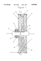
- FIG. 1 is a vertical sectional view through a first embodiment of coupler taken longitudinally of the rotary axis and with the input and output shaft shown in longitudinal side elevation;
- FIG. 2 through 5 show second, third, fourth, and fifth embodiments taken in the same manner as FIG. 1;
- FIG. 5A is a transverse sectional of the fifth embodiment taken as indicated by line 5A--5A in FIG. 5;
- FIG. 6 is a vertical sectional view of a sixth embodiment taken in the same manner as FIG. 1, and with the input and output shafts offset from one another;
- FIG. 6B is a transverse sectional view taken like FIG. 6A and illustrating a further embodiment
- FIG. 7 illustrates a magnetic disc unit in elevation and is taken as indicted by line 7--7 in FIG. 1.
- FIG. 8, 9 and 10 illustrate three alternative arrangements of permanent magnets on a magnetic disc viewed as in FIG. 7.
- FIG. 11 is a further embodiment taken in the same manner as FIG. 1.
- input and output shafts 8-9 are coaxial and nonferrous electroconductive plates 10--10' are connected together at their periphery by a connecting ring 12 held in place by bolts 14.
- the plates 10--10' are preferably copper plates or laminated copper plates.
- Plate 10 has an outer hub 16 secured thereto as by bolts 18, and this hub has a keyway fitting over a key 19 in turn fitting into a keyway at the outer end portion of the input shaft 8.
- a set screw 20 fixes the position of the plate 10 along the shaft 8.
- the other electroconductive plate 10' has a center opening 21 for the free passage of the output shaft 9.
- This shaft has a keyway receiving a key 22 which fits into a keyway presented by the hub 23 of a magnetic disc 24 containing permanent magnets 25.
- the air gaps 26-27 between the magnetic disc 12 and the electroconductive plates 10--10' are fixed in width.
- the magnetic disc 12 When the input shaft 8 is rotated about its longitudinal rotary axis, thereby rotating the electroconductive plates 10--10', the magnetic disc 12 responsively picks up speed by way of magnetic friction between the magnetic disc and both of the plates 10--10'. Since there is no physical connection between the shafts 8-9, slippage can occur therebetween, thereby protecting the input shaft and related drive mechanism from overloading caused by locking of the output shaft 9 due, for example, to freezing of a bearing thereon.
- the magnetic disc means comprises a pair of magnetic discs 12a--12a' having opposed hubs 28--28' slidably mounted on splines 30 provided on the output shaft 9.
- the hubs 28--28' are biased apart by compression springs 31 connected at their ends to the hubs.
- the electroconductive plates 10--10' are provided with hubs 32--32' secured thereto by a plurality of bolts 33--33'.
- the hubs 32--32' have a keyway fitting over respective keys 34--34', in turn fitting keyways at the opposing end portions of the input and output shafts 8-9.
- the input shaft 8 projects beyond the plate 10 to receive a bushing 36 in the hub of a magnetic disc 24'.
- This bushing 36 is free to rotate on the input shaft.
- the bushing and magnetic disc 24' comprise an idler rotor assembly permitting the disc 24' to rotate relative to the input shaft 8 and electroconductive plate 10. Adequate spacing is provided between the plates 10--10' to leave space for air gaps 26-27 between the plates and the magnetic disc 24'.
- rotation of the input shaft 8 results in magnetic friction between the electroconductive plate 10 and the magnetic disc 24' and the resulting rotation of the magnetic disc causes rotation of the output shaft 9 by way of magnetic friction between the disc 24' and electroconductive plate 10'. If the output shaft 9 seizes, the coupler permits the magnetic idler disc 24' and plate 10' to turn relative to the input shaft 8 and relative to one another.
- the electroconductive plate 10 is connected to the input shaft 8 in the same manner as in the first embodiment, but is not connected to the other electroconductive plate 10'.
- the latter has a hub 38 slide-mounted on splines 40 provided by the output shaft 9 and is "biased by a compression spring 42 toward the input shaft 8.
- a collar 43 is fixed by a set screw 44 on the output shaft 9 to serve as a seat for the spring 42.
- a bearing unit 46 mounted in a magnetic disc 24" so that the latter is an idler.
- the splined end portion of the output shaft 9 projects into close proximity with the input shaft 8.
- the magnetic disc 24" When the fourth embodiment is in operation by rotation of the input shaft 8, the magnetic disc 24" is attracted to the electroconductive plate 10 and slides on the output shaft 9 while commencing rotation responsive to magnetic friction.
- the magnetic disc 24" self establishes a minimum air gap from the plate 10.
- magnetic attraction and magnetic friction between the disc 24" and the electroconductive plate 10' causes the plate 10' to rotate and to slide with the disc 24" toward the other plate 10.
- the output shaft 9 seizes, thereby stopping rotation of the electroconductive plate 10' the resulting repulsion between the disc 24" and the plate 10' because of the sudden difference in their relative speeds forces the plate 10' away from the magnetic disc in opposition to the spring 42 which remains free to rotate with the other plate 10.
- the magnetic disc normally drifts toward the load-connected electroconductive plate such that the air gap between the magnetic disc and the motor-driven plate is larger than the gap between the magnetic disc and the load-connected plate. If the sum of the air gaps is then gradually decreased, thereby decreasing the gap between the motor-driven electroconductive plate and the magnetic disc, the rotational slippage therebetween decreases and the speed of the magnetic disc and the load-connected plate responsively increases. The air gap between the magnetic disc and the motor-driven electroconductive plate will remain larger than the gap between the magnetic disc and the load-connected magnetic plate.
- Electroconductive plate 10 has a hub 60 slide-mounted on splines 61 on the output shaft 9 so that the plate 10' is coupled to the output shaft, but is free to slide therealong.
- a circumferentially grooved collar 62 is mounted by a throwout bearing 64 on the output shaft 9 so that the collar 62 is free to slide along the output shaft without rotating.
- a yoke member 66 interfits with the circumferential groove 63 in the collar 62 and is swing-mounted at its opposite end by a pivot pin 68 on a mounting block 70. Movement of the yoke member 66 to responsively slide the collar 62 on the output shaft 9 is controlled by a servo motor 70 having a threaded shaft 71 extending through a nut 72 which has a pin 73 extending through a slot 74 in the arm of the yoke member.
- the electroconductive plate 10' can have a slide range between a no-load transfer position in which the air gap between the magnetic disc and plate 10' is so large that the plate 10' remains at rest when the input shaft 8' is turning at full speed, and a near full-load transfer position in which said air gap is small enough for full-speed driving of the load-connected electroconductive plate 10' via the magnetic disc.
- this range there can be controlled slippage of the load-connected plate 10' relative to the plate 10 and magnetic disc to provide speed adjustment of the load while the driving motor operates at constant speed.
- the output shaft 9 can become the input shaft and vice versa.
- the magnetic disc 59 can be mounted as an idler on an extension of the output shaft 9 rather than on an extension of the input shaft 8.
- the sixth embodiment illustrates an example in which the input shaft 8 and output shaft 9 are not coaxial.
- two pairs of bearings 70--70' and 71--71' are mounted in a housing 72 for receiving the shafts 8-9.
- a magnetic disc unit 74 is fitted by a key 75 on the output shaft 9, and the electroconductive plates 10--10' together with a spacer 76 are fitted by a key 77 on the input shaft 8.
- the plates 10--10' partly overlap the magnetic disc 74 and rotation of the input shaft 8 causes rotation of the output shaft 9 by way of magnetic friction between the magnetic disc 74 and electroconductive plates 10--10'.
- the output shaft 9 will rotate proportionately faster similar to meshed gears having different pitch diameters. It will be appreciated, as shown in FIG. 6B that a second output shaft 9' can be provided which is coupled to another magnetic disc 74' which is partly overlapped by the electroconductive plates 10--10'.
- the permanent magnets used in the magnetic disc units are preferably of the rare earth type, and namely, the lanthonides such as samarium cobalt and neodymium iron boron. These magnets have magnetic properties exceeding the arnico and ceramic types.
- the magnets may be rectangular or circular in cross-section, for example, and are bonded into complementing openings provided in a disc which may be plastic, metal or ceramic.
- the magnets are arranged symmetrically with adjacent magnets arranged so that they present opposite poles on each side of the disc.
- the magnets can also be stacked end for end, positive pole opposite negative pole, in the disc openings.
- FIG. 7 illustrates the magnetic disc example in FIG. 1 in which four evenly spaced rectangular openings 80 are provided in the disc 24 to receive four sets of permanent magnets 25.
- Each set comprises two side-by-side stacks of rectangular magnets with three magnets per stack.
- the pairs in each set have their poles arranged oppositely from one another, i.e., one pair has its poles arranged in a N-S-N-S-N-S order from one face of the disc to the other face, whereas the adjoining pair has its poles arranged in a S-N-S-N-S-N order.
- the magnets project a short distance beyond the faces of the disc.
- FIG. 7 example of magnetic disc was successfully used in a FIG. 5 coupling, for example, in experiments in which a 5 hp. synchronous motor, 3600 rpm, was used to drive a centrifugal pump.
- the electroconductive plates were copper, 1/2 inches thick, with an 8 inch diameter, and the magnetic disc was of the same diameter and had a thickness of 11/8".
- the permanent magnets were each 1 ⁇ 2 inches, and 1/2 inch thick, stacked in threes so that each magnet projected 3/16 inches beyond a respective face of the disc.
- FIG. 8 illustrates an alternative magnetic disc example utilizing rectangular permanent magnets 25 arranged with alternating north-south poles in equally spaced relation in a circular pattern in rectangular openings 180 in a disc 124.
- FIG. 9 illustrates a similar arrangement with circular permanent magnets 125 mounted in circular holes 280 in a disc 224.
- FIG. 10 shows a further example in which side-by-side permanent magnet sectors 225 are arranged in a ring on each side of a disc 324.
- FIG. 11 shows a preferred magnetic coupler similar to that illustrated in FIG. 3, but in which the non-ferrous electroconductive plates 10a--10'a (copper, for example) have been backed by steel plates 11--11' attached thereto in any suitable manner such, for example, as by rivets.
- Hub members 32a--32'a are bolt connected to the steel plates 11--11' and receive tapered end plugs 81--81' which are attached to the shafts 8-9 by keys 34--34'.
- the end plugs 81--81' are connected to the hub members 32a--32'a in any suitable manner.
- Force-fitted into the hub member 32a is a steel tube 21 which projects through the plates 10-11 as a stub shaft toward the plate 10' to slidably receive a bushing in the hub of a magnetic disc 24 containing permanent magnets 25.
- a copper plate backed by a steel plate is more efficient in the practice of this invention for the electroconductive plates than when a copper plate, or laminated copper plate is used, as previously described.
- plates 10--10' which are 0.25 inches thick can be used in conjunction with steel backing plates 11--11' which are 0.50 inches thick, and obtain results superior to use of copper or laminated copper plates which are 0.50 inches thick.
- the thickness of the steel backing plates 11--11' is selected for rigidity when subjected to the magnetic forces encountered when rotating and does not affect the coupling efficiency.
- the flux density in the copper plates 10a--10'a is increased during operation of the coupler. Air gaps 26-27 are maintained between the magnetic disc 24 and the copper plates 10--10' when they are rotating even though there is axial attraction between the steel backing plates 11--11' and the magnets 25 when the coupling components are stationary.
Abstract
Description
Claims (18)
Priority Applications (9)
| Application Number | Priority Date | Filing Date | Title |
|---|---|---|---|
| US08/237,031 US5477094A (en) | 1993-05-21 | 1994-05-03 | Permanent magnet coupling and transmission |
| US08/546,066 US5668424A (en) | 1993-05-21 | 1995-10-20 | Permanent magnet coupling and transmission |
| US08/546,480 US5739627A (en) | 1993-05-21 | 1995-10-20 | Adjustable permanent magnet coupler |
| US08/616,370 US5691587A (en) | 1993-05-21 | 1996-03-15 | Magnetic centrifugal clutch |
| US08/616,905 US5712519A (en) | 1993-05-21 | 1996-03-15 | Magnetic power transfer system |
| US08/617,314 US5712520A (en) | 1993-05-21 | 1996-03-18 | Permanent magnet braking system |
| US08/803,365 US5880548A (en) | 1993-05-21 | 1997-02-20 | Adjustable magnetic coupler |
| US08/834,094 US5834872A (en) | 1993-05-21 | 1997-04-14 | Adjustable magnetic coupler |
| US08/898,708 US5909073A (en) | 1993-05-21 | 1997-07-22 | Magnetic clutches and couplings with sheaves |
Applications Claiming Priority (2)
| Application Number | Priority Date | Filing Date | Title |
|---|---|---|---|
| US08/065,867 US5477093A (en) | 1993-05-21 | 1993-05-21 | Permanent magnet coupling and transmission |
| US08/237,031 US5477094A (en) | 1993-05-21 | 1994-05-03 | Permanent magnet coupling and transmission |
Related Parent Applications (1)
| Application Number | Title | Priority Date | Filing Date |
|---|---|---|---|
| US08/065,867 Continuation-In-Part US5477093A (en) | 1993-05-21 | 1993-05-21 | Permanent magnet coupling and transmission |
Related Child Applications (2)
| Application Number | Title | Priority Date | Filing Date |
|---|---|---|---|
| US08/546,480 Continuation-In-Part US5739627A (en) | 1993-05-21 | 1995-10-20 | Adjustable permanent magnet coupler |
| US08/546,066 Continuation US5668424A (en) | 1993-05-21 | 1995-10-20 | Permanent magnet coupling and transmission |
Publications (1)
| Publication Number | Publication Date |
|---|---|
| US5477094A true US5477094A (en) | 1995-12-19 |
Family
ID=22065677
Family Applications (4)
| Application Number | Title | Priority Date | Filing Date |
|---|---|---|---|
| US08/065,867 Expired - Lifetime US5477093A (en) | 1993-05-21 | 1993-05-21 | Permanent magnet coupling and transmission |
| US08/144,674 Expired - Lifetime US5473209A (en) | 1993-05-21 | 1993-10-29 | Permanent magnet braking system for drive shafts |
| US08/237,031 Expired - Lifetime US5477094A (en) | 1993-05-21 | 1994-05-03 | Permanent magnet coupling and transmission |
| US08/546,066 Expired - Lifetime US5668424A (en) | 1993-05-21 | 1995-10-20 | Permanent magnet coupling and transmission |
Family Applications Before (2)
| Application Number | Title | Priority Date | Filing Date |
|---|---|---|---|
| US08/065,867 Expired - Lifetime US5477093A (en) | 1993-05-21 | 1993-05-21 | Permanent magnet coupling and transmission |
| US08/144,674 Expired - Lifetime US5473209A (en) | 1993-05-21 | 1993-10-29 | Permanent magnet braking system for drive shafts |
Family Applications After (1)
| Application Number | Title | Priority Date | Filing Date |
|---|---|---|---|
| US08/546,066 Expired - Lifetime US5668424A (en) | 1993-05-21 | 1995-10-20 | Permanent magnet coupling and transmission |
Country Status (14)
| Country | Link |
|---|---|
| US (4) | US5477093A (en) |
| EP (1) | EP0699358B1 (en) |
| JP (1) | JP3800430B2 (en) |
| KR (1) | KR100355256B1 (en) |
| AT (1) | ATE162016T1 (en) |
| AU (1) | AU678834B2 (en) |
| BR (1) | BR9406542A (en) |
| CA (1) | CA2161965C (en) |
| DE (1) | DE69407782T2 (en) |
| DK (1) | DK0699358T3 (en) |
| ES (1) | ES2113661T3 (en) |
| GR (1) | GR3026455T3 (en) |
| NO (1) | NO307320B1 (en) |
| WO (1) | WO1994028614A1 (en) |
Cited By (50)
| Publication number | Priority date | Publication date | Assignee | Title |
|---|---|---|---|---|
| WO1997034359A1 (en) * | 1996-03-15 | 1997-09-18 | Magna Force, Inc. | Magnetic power transfer system |
| WO1998037617A1 (en) * | 1997-02-20 | 1998-08-27 | Magna Force, Inc. | Adjustable magnetic coupler |
| US5903075A (en) * | 1998-06-10 | 1999-05-11 | Magna Force, Inc. | Permanent magnet coupler with soft start adjustment system |
| US6007303A (en) * | 1997-01-22 | 1999-12-28 | Schmidt; Eugen | Controllable coolant pump for motor vehicles |
| US6054788A (en) * | 1998-08-12 | 2000-04-25 | Reliance Electric Industrial Company | Magnetic power transmission coupling |
| WO2002031370A1 (en) * | 2000-10-11 | 2002-04-18 | Andrew Boyd French | Drive apparatus |
| US6682430B2 (en) | 2001-03-15 | 2004-01-27 | Magnadrive Corporation | Adjustable magnetic coupler |
| US6762523B1 (en) * | 1999-08-11 | 2004-07-13 | The Swatch Group Management Services Ag | Continuously variable electromagnetic transmission |
| US20050189830A1 (en) * | 2004-03-01 | 2005-09-01 | Corbin Philip Iii | Apparatus for transferring torque magnetically |
| US6949854B1 (en) * | 2001-03-16 | 2005-09-27 | Michael Schlicht | Method and apparatus for a continuously variable-ratio transmission |
| US20050236919A1 (en) * | 2003-01-17 | 2005-10-27 | Magnetic Torque International, Ltd. | Torque converter system and method of using the same |
| US20050279154A1 (en) * | 2004-06-21 | 2005-12-22 | Fout Gary E | Method and apparatus for determining system integrity for an oilfield machine |
| US20060123936A1 (en) * | 2001-10-11 | 2006-06-15 | Andrew French | Drive apparatus |
| US20060170304A1 (en) * | 2004-11-19 | 2006-08-03 | Magnadrive Corporation | Magnetic coupling devices and associated methods |
| US20060219128A1 (en) * | 2005-03-17 | 2006-10-05 | Lingqun Li | Suspending-rail permanent magnetic levitation train system |
| US20060225358A1 (en) * | 2005-04-11 | 2006-10-12 | Haag Ronald H | Apparatus and method for providing a drive device for a vehicle door |
| US20060244322A1 (en) * | 2005-04-29 | 2006-11-02 | Lingqun Li | One-wheel and bi-pole magnetic driving apparatus |
| US20060255676A1 (en) * | 2003-01-17 | 2006-11-16 | Magnetic Torque International, Ltd. | Power generating systems |
| US20070044677A1 (en) * | 2005-08-25 | 2007-03-01 | Lingqun Li | Permanent magnetic levitation bogie apparatus |
| EP1203440B1 (en) * | 1999-08-04 | 2007-05-16 | Magna Force, Inc. | Permanent magnet coupler with adjustable air gaps |
| US7233088B2 (en) | 2003-01-17 | 2007-06-19 | Magnetic Torque International, Ltd. | Torque converter and system using the same |
| US7243461B2 (en) | 2003-03-19 | 2007-07-17 | Rogers Jr Lloyd W | Hinge mechanism for a sliding door |
| US20080024027A1 (en) * | 2006-07-31 | 2008-01-31 | Caterpillar Inc. | Axial-flux electric machine |
| US20080024035A1 (en) * | 2006-07-31 | 2008-01-31 | Caterpillar Inc. | Power system |
| US7325361B2 (en) | 2003-03-19 | 2008-02-05 | Delphi Technologies, Inc. | Apparatus and method for providing a modular sliding door mechanism |
| US20080196890A1 (en) * | 2002-04-02 | 2008-08-21 | M-I Llc | Magnetic power transmission devices for oilfield applications |
| US20090085419A1 (en) * | 2007-09-28 | 2009-04-02 | James Arseneaux | Hybrid touchdown bearing system |
| US20090159373A1 (en) * | 2007-12-10 | 2009-06-25 | Rapid Egress Descent Systems, Ltd. | Descent control device |
| CN101814820A (en) * | 2010-02-26 | 2010-08-25 | 王荣松 | Permanent-magnetic drive speed adjustor |
| US20100277021A1 (en) * | 2005-02-26 | 2010-11-04 | Corbin Iii Philip | Apparatus for transferring torque magnetically |
| US20100308947A1 (en) * | 2008-02-14 | 2010-12-09 | Daniel Farb | Magnetic coupling devices |
| US20110114907A1 (en) * | 2009-11-13 | 2011-05-19 | Hartman Gregory A | Single cable descent control device |
| US20120137682A1 (en) * | 2010-12-06 | 2012-06-07 | Wartsila Finland Oy | Turbocharging arrangement and method for operating an internal combustion engine |
| CN103107674A (en) * | 2013-01-14 | 2013-05-15 | 浙江大学 | Disks of permanent magnet eddy coupling with smaller time-lag effects in disc type |
| CN103378710A (en) * | 2012-04-16 | 2013-10-30 | 杰达电能科技股份有限公司 | Permanent magnetic coupling with heat radiating blades |
| CN103580446A (en) * | 2013-11-04 | 2014-02-12 | 上海曜中能源科技有限公司 | Torque limitation universal type permanent magnet coupler |
| DE102013008109A1 (en) * | 2013-05-11 | 2014-11-13 | Gelu Bejan | Timing disc for non-contact power transmission by permanent magnets |
| CN104253523A (en) * | 2014-10-17 | 2014-12-31 | 北京必可测科技股份有限公司 | Combined permanent magnet eddy current speed governor |
| US9016432B2 (en) | 2007-12-10 | 2015-04-28 | Rapid Egress Descent Systems Ltd. | Descent control device |
| CN104682661A (en) * | 2015-03-10 | 2015-06-03 | 盐城华力达科技有限公司 | Permanent magnet coupler |
| US20160111936A1 (en) * | 2012-05-08 | 2016-04-21 | Empire Magnetics Inc. | Wind Power Generator and Coupling |
| US9523231B2 (en) | 2003-11-10 | 2016-12-20 | Strattec Power Access Llc | Attachment assembly and drive unit having same |
| US20170310200A1 (en) * | 2014-09-25 | 2017-10-26 | Junqi DIAO | Fixed magnetic gap permanent magnet speed governor |
| US10086853B2 (en) * | 2010-02-01 | 2018-10-02 | Ride, Inc. | Movable cable loop descent system |
| US10337216B2 (en) | 2014-01-02 | 2019-07-02 | Strattec Power Access Llc | Vehicle door |
| PL424390A1 (en) * | 2018-01-26 | 2019-07-29 | Instytut Techniki Górniczej Komag | Adjustable magnetic overload coupling |
| US10498211B2 (en) | 2014-07-30 | 2019-12-03 | Jiangsu Magnet Valley Technologies Co., Ltd. | Winding-type permanent magnet coupling transmission device |
| US11296588B2 (en) | 2019-10-15 | 2022-04-05 | Darrell Schmidt Enterprises, Inc. | Magnetic coupler |
| US11376946B2 (en) * | 2020-02-24 | 2022-07-05 | Deere & Company | Magnetic couplers for shaft assembly |
| US11522436B2 (en) | 2019-10-15 | 2022-12-06 | Darrell Schmidt Enterprises, Inc. | Permanently magnetized enhanced generator |
Families Citing this family (85)
| Publication number | Priority date | Publication date | Assignee | Title |
|---|---|---|---|---|
| US5691587A (en) * | 1993-05-21 | 1997-11-25 | Magna Force, Inc. | Magnetic centrifugal clutch |
| US5712520A (en) * | 1993-05-21 | 1998-01-27 | Magna Force, Inc. | Permanent magnet braking system |
| US5739627A (en) * | 1993-05-21 | 1998-04-14 | Magna Force, Inc. | Adjustable permanent magnet coupler |
| US5751127A (en) * | 1995-07-06 | 1998-05-12 | Grimes Aerospace Company | Magnet brake |
| AU746941B2 (en) * | 1997-02-20 | 2002-05-09 | Magnadrive Corporation | Adjustable magnetic coupler |
| US6348751B1 (en) * | 1997-12-12 | 2002-02-19 | New Generation Motors Corporation | Electric motor with active hysteresis-based control of winding currents and/or having an efficient stator winding arrangement and/or adjustable air gap |
| DE19914021C2 (en) * | 1999-03-19 | 2002-01-31 | Siemens Ag | Multi-pole, permanently excited rotor for a rotating electrical machine and method for producing such a rotor |
| US6242832B1 (en) * | 1999-10-18 | 2001-06-05 | Magna Force, Inc. | Self unloading magnetic coupler |
| DE10026176A1 (en) * | 2000-05-26 | 2002-01-10 | Schleifring Und Appbau Gmbh | Holding and contacting device for sliding contacts; PCB brush block |
| FR2818202B1 (en) * | 2000-12-14 | 2005-04-22 | Jacques Clausin | ENERGY SAVING DEVICE FOR THERMAL MOTOR VEHICLES USING AN INERTREWHEEL CONTROLLED BY A PASSIVE ELECTROMAGNETIC COUPLER ASSOCIATED WITH AN AUTOMATE AND A ROBOTIZED SPEED BOX |
| US6577037B2 (en) * | 2001-07-03 | 2003-06-10 | Magnadrive Corporation | Self-unloading magnetic coupler |
| CN1172426C (en) * | 2002-06-21 | 2004-10-20 | 魏乐汉 | Multi-layer magnetic engaged wheel and magnetic gearing device |
| JP3811442B2 (en) * | 2002-11-07 | 2006-08-23 | Smc株式会社 | Magnetic damper and actuator having the same |
| US20040262105A1 (en) * | 2003-05-13 | 2004-12-30 | Zhesheng Li | Eddy-current wheelend retarder featuring modified rotor skin effect |
| CA2430157A1 (en) | 2003-05-30 | 2004-11-30 | Tm4 Inc. | Electric vehicle traction system |
| JP2005048793A (en) * | 2003-07-29 | 2005-02-24 | Usui Kokusai Sangyo Kaisha Ltd | Magnet type fan clutch device |
| US20060073950A1 (en) * | 2004-09-30 | 2006-04-06 | Ivanko Barbell Company | Dumbbell assembly system |
| WO2007005560A2 (en) * | 2005-06-30 | 2007-01-11 | Magnetar Technologies Corp. | Axial rotary eddy current brake with adjustable braking force |
| US7513349B2 (en) * | 2005-11-30 | 2009-04-07 | Tm4 Inc. | Multi-position clutch |
| US7549950B1 (en) * | 2007-08-01 | 2009-06-23 | Recreation Supply, Inc. | Weight bar slide assembly |
| US7948141B2 (en) * | 2007-11-22 | 2011-05-24 | Seiko Epson Corporation | Electric motor device |
| JP2009148146A (en) * | 2007-11-22 | 2009-07-02 | Seiko Epson Corp | Electric motor device |
| CN101771373A (en) * | 2008-12-30 | 2010-07-07 | 鸿富锦精密工业(深圳)有限公司 | Overload protection device of motor |
| CN101997393B (en) * | 2009-08-11 | 2012-07-25 | 余亚莉 | Cylinder-type transmission shaft permanent-magnetic coupler capable of adjusting electromagnetic torque |
| SE534221C2 (en) | 2009-10-26 | 2011-06-07 | A drive system for a tank cleaning device and a tank cleaning device | |
| KR100950782B1 (en) | 2009-10-28 | 2010-04-02 | 주식회사 3국산업 | System for excavator |
| US20110109182A1 (en) * | 2009-11-05 | 2011-05-12 | Jozef Andrzej Maj | Magnetic transmission |
| IT1396417B1 (en) * | 2009-11-24 | 2012-11-23 | Muratori | MAGNETIC BRAKING DEVICE |
| EP2444624A1 (en) * | 2009-12-04 | 2012-04-25 | Perkins Engines Company Limited | Turbocharger brake |
| US8742640B1 (en) | 2010-04-19 | 2014-06-03 | Mag-Trans Corporation | Electric motor and magnet transmission for motor vehicle |
| GB201013576D0 (en) * | 2010-08-12 | 2010-09-29 | Microtecnica Actuation Tech Ltd | Electromagnetic brake or clutch and method of operation |
| RU2451382C1 (en) * | 2011-04-14 | 2012-05-20 | Закрытое акционерное общество "Научно-исследовательский и конструкторский институт центробежных и роторных компрессоров им. В.Б. Шнеппа" | Electromagnet coupling gear with sealing screen |
| TWI442675B (en) * | 2011-07-12 | 2014-06-21 | Magneticcoupler | |
| DE102012202553A1 (en) * | 2012-02-20 | 2013-08-22 | Carl Zeiss Smt Gmbh | LITHOGRAPHY DEVICE WITH DAMPING DEVICE |
| WO2013143596A1 (en) * | 2012-03-29 | 2013-10-03 | Siemens Aktiengesellschaft | Magnetic gear box arrangement |
| US8994201B2 (en) * | 2012-04-11 | 2015-03-31 | Wind Labs, Inc. | Vertical axis wind turbine |
| US20140085914A1 (en) * | 2012-09-27 | 2014-03-27 | Sunrising Eco-Friendly Technology Co., Ltd. | Contactless Generator, Component Therein and Application Thereof |
| CN103095097A (en) * | 2012-12-20 | 2013-05-08 | 上海曜中能源科技有限公司 | Transmission system with permanent magnet speed regulation clutch |
| JP5920268B2 (en) * | 2013-03-26 | 2016-05-18 | 富士ゼロックス株式会社 | Image forming apparatus |
| DE102013209290B4 (en) * | 2013-05-21 | 2015-01-22 | Schaeffler Technologies Gmbh & Co. Kg | Roller device for a traction mechanism drive of a motor vehicle |
| TWI560977B (en) * | 2013-06-25 | 2016-12-01 | Sunrising Eco Friendly Technology Co Ltd | Movement power generator |
| TWI578667B (en) * | 2013-06-25 | 2017-04-11 | 升暘科技有限公司 | Movement power generator |
| NZ619034A (en) * | 2013-12-16 | 2015-03-27 | Eddy Current Ltd Partnership | An assembly to control relative speed of movement between parts |
| CN104836415A (en) * | 2014-02-11 | 2015-08-12 | 中兴杰达电能科技股份有限公司 | Speed-adjustable permanent magnetic actuator |
| CN103780051B (en) * | 2014-02-24 | 2016-04-06 | 哈尔滨工业大学 | Bilateral structure speed governing permanent magnetic coupling |
| WO2015137814A1 (en) * | 2014-03-13 | 2015-09-17 | Zytec International B.V. | Magnetic coupling assembly |
| NL2013219B1 (en) | 2014-03-13 | 2016-04-04 | Zytec Int B V | Magnetic coupling assembly. |
| DK201400181A1 (en) * | 2014-03-31 | 2015-10-12 | Applied Turbine Technologies Aps | Non-touching rotational contact |
| CN104184300A (en) * | 2014-07-30 | 2014-12-03 | 大连应达实业有限公司 | Rack-and-pinion moment-adjustable permanently magnetic coupler |
| CN104218772A (en) * | 2014-07-30 | 2014-12-17 | 大连应达实业有限公司 | Linear bearing guide rail type variable-torque permanent magnetic coupling |
| SG11201701192UA (en) | 2014-08-18 | 2017-03-30 | Eddy Current Ltd Partnership | Tuning of a kinematic relationship between members |
| MX364898B (en) | 2014-08-18 | 2019-05-13 | Eddy Current Lp | Latching devices. |
| CN111817532B (en) | 2014-08-18 | 2023-07-28 | 涡流有限合伙公司 | Adjustment of the movement relationship between components |
| TWI515700B (en) * | 2014-10-14 | 2016-01-01 | 巨大機械工業股份有限公司 | Bike trainer |
| AU2015355674A1 (en) | 2014-12-04 | 2017-06-08 | Eddy Current Limited Partnership | Eddy current brake configurations |
| US11050336B2 (en) | 2014-12-04 | 2021-06-29 | Eddy Current Limited Partnership | Methods of altering eddy current interactions |
| EP3226980B1 (en) | 2014-12-04 | 2023-05-10 | Eddy Current Limited Partnership | Energy absorbing apparatus |
| EP3226978A4 (en) | 2014-12-04 | 2018-05-02 | Eddy Current Limited Partnership | Latch activation between elements |
| US10693360B2 (en) * | 2014-12-04 | 2020-06-23 | Eddy Current Limited Partnership | Transmissions incorporating eddy current braking |
| CN104362831B (en) * | 2014-12-05 | 2016-08-31 | 刁俊起 | A kind of permanent-magnet speed governor of fixing magnetic gap |
| JP2017005876A (en) * | 2015-06-10 | 2017-01-05 | ナブテスコ株式会社 | Rotary electric machine and non-contact generator |
| CN105634243B (en) * | 2015-07-08 | 2018-11-27 | 安徽沃弗电力科技有限公司 | Liquid-cooling type permanent-magnet speed governor |
| DE102015011959A1 (en) * | 2015-09-18 | 2017-03-23 | INGENIEURBüRO CAT M. ZIPPERER GMBH | Starter arrangement |
| CN106602840A (en) * | 2015-10-14 | 2017-04-26 | 华电宁夏灵武发电有限公司 | Air-cooling fan capable of avoiding torsional vibration |
| CN105365846B (en) * | 2015-12-01 | 2018-04-17 | 王向东 | Permanent magnetism deceleration top |
| BR122021013798B1 (en) | 2015-12-18 | 2023-04-18 | Eddy Current Limited Partnership | VARIABLE OPERATING CONTROL MECHANISM FOR MOTOR SYSTEM |
| AR107910A1 (en) * | 2016-03-18 | 2018-06-28 | Alfa Laval Corp Ab | A SYSTEM AND A METHOD FOR A VARIABLE SPEED REFRIGERATION FAN IN A SKATE MOUNTED COMPRESSOR |
| US10840794B2 (en) * | 2017-01-12 | 2020-11-17 | James Abella | Gravity energy generator |
| US10457148B2 (en) | 2017-02-24 | 2019-10-29 | Epic Battery Inc. | Solar car |
| US10587221B2 (en) | 2017-04-03 | 2020-03-10 | Epic Battery Inc. | Modular solar battery |
| CN108574395A (en) * | 2017-03-09 | 2018-09-25 | 李启飞 | Induction type powered magnetic differential drive system |
| CN108574382A (en) * | 2017-03-09 | 2018-09-25 | 李启飞 | induction machine |
| CN108574383A (en) * | 2017-03-09 | 2018-09-25 | 李启飞 | The very big load of D types is adjustable induction machine |
| CN107370336B (en) * | 2017-06-19 | 2019-08-02 | 江苏大学 | A kind of disc type speed regulation magnetic coupling based on Bevel Gear Transmission |
| CN107612278A (en) * | 2017-09-18 | 2018-01-19 | 安徽叁旺网络信息技术有限公司 | A kind of automatic clutch-type transmission gear for electric motor and method |
| EP3474430B1 (en) * | 2017-10-19 | 2022-08-24 | Hamilton Sundstrand Corporation | System and method for calibrating an air gap in a servovalve torque motor |
| CN109617363B (en) * | 2018-10-30 | 2019-12-13 | 江苏科岭能源科技有限公司 | High-speed long and thin section of thick bamboo permanent magnet coupler |
| US11489082B2 (en) | 2019-07-30 | 2022-11-01 | Epic Battery Inc. | Durable solar panels |
| CN110957891A (en) * | 2019-12-24 | 2020-04-03 | 北京青云航空仪表有限公司 | High damping moment density hysteresis damper |
| CN111711338A (en) * | 2020-05-11 | 2020-09-25 | 南京玛格耐特智能科技有限公司 | Speed-regulating horizontal air-cooled permanent magnet coupler |
| EP4037166A1 (en) * | 2021-01-29 | 2022-08-03 | Magnax | Axial flux motor with field weakening functionality |
| RU207680U1 (en) * | 2021-04-12 | 2021-11-11 | Российская Федерация, в лице которой выступает Государственная корпорация по атомной энергии "Росатом" | Magnetic transmission |
| CN113437837B (en) * | 2021-05-13 | 2022-06-10 | 山西江淮重工有限责任公司 | Anti-friction disc alarm device, disc type permanent magnet eddy current coupling and alarm method thereof |
| CN113541440B (en) * | 2021-09-07 | 2021-12-07 | 南京华脉科技股份有限公司 | Magnetic force safety type coupler |
| CN117175889B (en) * | 2023-11-03 | 2024-01-23 | 东北大学 | Permanent-magnet retarder capable of automatically adjusting braking torque through air cooling |
Citations (7)
| Publication number | Priority date | Publication date | Assignee | Title |
|---|---|---|---|---|
| US2971105A (en) * | 1959-04-13 | 1961-02-07 | Eaton Mfg Co | Eddy-current machine |
| US3555321A (en) * | 1967-08-03 | 1971-01-12 | Olympia Werke Ag | Eddy current brake for use in business machines or the like |
| US3763968A (en) * | 1971-03-09 | 1973-10-09 | J Noly | Electro magnetic braking device |
| US3811740A (en) * | 1971-04-24 | 1974-05-21 | Cnen | Self-centering rotary magnetic suspension device |
| US3822390A (en) * | 1973-09-10 | 1974-07-02 | Lear Siegler Inc | Adjustable-torque magnetic brake |
| US4152617A (en) * | 1977-11-22 | 1979-05-01 | Dana Corporation | Selectively variable torque magnetic brake |
| US4826150A (en) * | 1986-02-20 | 1989-05-02 | Minoura Carrier & Stand Works Co., Ltd. | Resistance applying means for exercising apparatus |
Family Cites Families (15)
| Publication number | Priority date | Publication date | Assignee | Title |
|---|---|---|---|---|
| US2437416A (en) * | 1941-11-07 | 1948-03-09 | Nat Simplex Bludworth Inc | Deep and shoal alarm |
| US3267310A (en) * | 1963-05-07 | 1966-08-16 | Indiana General Corp | Magnetic transmission |
| FR1375230A (en) * | 1963-09-04 | 1964-10-16 | Electronique & Automatisme Sa | Advanced magnetic clutches |
| DE1255189B (en) * | 1964-09-25 | 1967-11-30 | Licentia Gmbh | Slip clutch with an inductor part, which carries at least one toroidal excitation winding, and with disc-shaped yokes |
| NL6713597A (en) * | 1967-10-06 | 1969-04-09 | ||
| US3567976A (en) * | 1969-07-15 | 1971-03-02 | Max Alth | Eddy current brakes |
| US3573517A (en) * | 1970-03-02 | 1971-04-06 | Sargentwelch Scient Co | Magnetic drive |
| DE2217437A1 (en) * | 1972-04-12 | 1973-10-25 | Motoren Turbinen Union | ROTARY VIBRATION DAMPER |
| JPS5445707A (en) * | 1977-09-17 | 1979-04-11 | Canon Inc | Dc electric machine |
| US4298773A (en) * | 1978-07-14 | 1981-11-03 | Diab Khaled M | Method and system for 5-bit encoding of complete Arabic-Farsi languages |
| US4819388A (en) * | 1981-06-26 | 1989-04-11 | Kirkland Wyatt S | Spin-blast tool with rotational velocity restraint |
| US4446392A (en) * | 1982-05-13 | 1984-05-01 | Eaton Corporation | Electromagnetic coupling device |
| DE3530746A1 (en) * | 1985-08-28 | 1987-03-05 | Heinz Stuefer | Eddy-current brake |
| JPH03112358A (en) * | 1989-09-26 | 1991-05-13 | Matsushita Electric Ind Co Ltd | Magnetic clutch |
| JPH05179984A (en) * | 1991-12-25 | 1993-07-20 | Fuji Oozx Kk | Power transmission device from engine to auxiliary machine |
-
1993
- 1993-05-21 US US08/065,867 patent/US5477093A/en not_active Expired - Lifetime
- 1993-10-29 US US08/144,674 patent/US5473209A/en not_active Expired - Lifetime
-
1994
- 1994-05-03 US US08/237,031 patent/US5477094A/en not_active Expired - Lifetime
- 1994-05-16 WO PCT/US1994/005518 patent/WO1994028614A1/en active IP Right Grant
- 1994-05-16 JP JP50076095A patent/JP3800430B2/en not_active Expired - Fee Related
- 1994-05-16 ES ES94917422T patent/ES2113661T3/en not_active Expired - Lifetime
- 1994-05-16 AU AU69155/94A patent/AU678834B2/en not_active Expired
- 1994-05-16 DE DE69407782T patent/DE69407782T2/en not_active Expired - Lifetime
- 1994-05-16 DK DK94917422T patent/DK0699358T3/en active
- 1994-05-16 BR BR9406542A patent/BR9406542A/en not_active IP Right Cessation
- 1994-05-16 KR KR1019950705245A patent/KR100355256B1/en not_active IP Right Cessation
- 1994-05-16 AT AT94917422T patent/ATE162016T1/en active
- 1994-05-16 CA CA002161965A patent/CA2161965C/en not_active Expired - Lifetime
- 1994-05-16 EP EP94917422A patent/EP0699358B1/en not_active Expired - Lifetime
-
1995
- 1995-10-20 US US08/546,066 patent/US5668424A/en not_active Expired - Lifetime
- 1995-11-20 NO NO954680A patent/NO307320B1/en not_active IP Right Cessation
-
1998
- 1998-03-27 GR GR980400639T patent/GR3026455T3/en unknown
Patent Citations (7)
| Publication number | Priority date | Publication date | Assignee | Title |
|---|---|---|---|---|
| US2971105A (en) * | 1959-04-13 | 1961-02-07 | Eaton Mfg Co | Eddy-current machine |
| US3555321A (en) * | 1967-08-03 | 1971-01-12 | Olympia Werke Ag | Eddy current brake for use in business machines or the like |
| US3763968A (en) * | 1971-03-09 | 1973-10-09 | J Noly | Electro magnetic braking device |
| US3811740A (en) * | 1971-04-24 | 1974-05-21 | Cnen | Self-centering rotary magnetic suspension device |
| US3822390A (en) * | 1973-09-10 | 1974-07-02 | Lear Siegler Inc | Adjustable-torque magnetic brake |
| US4152617A (en) * | 1977-11-22 | 1979-05-01 | Dana Corporation | Selectively variable torque magnetic brake |
| US4826150A (en) * | 1986-02-20 | 1989-05-02 | Minoura Carrier & Stand Works Co., Ltd. | Resistance applying means for exercising apparatus |
Cited By (86)
| Publication number | Priority date | Publication date | Assignee | Title |
|---|---|---|---|---|
| WO1997034359A1 (en) * | 1996-03-15 | 1997-09-18 | Magna Force, Inc. | Magnetic power transfer system |
| US6007303A (en) * | 1997-01-22 | 1999-12-28 | Schmidt; Eugen | Controllable coolant pump for motor vehicles |
| WO1998037617A1 (en) * | 1997-02-20 | 1998-08-27 | Magna Force, Inc. | Adjustable magnetic coupler |
| SG99949A1 (en) * | 1997-02-20 | 2003-11-27 | Magna Force Inc | Coupler |
| US5903075A (en) * | 1998-06-10 | 1999-05-11 | Magna Force, Inc. | Permanent magnet coupler with soft start adjustment system |
| US6054788A (en) * | 1998-08-12 | 2000-04-25 | Reliance Electric Industrial Company | Magnetic power transmission coupling |
| EP1203440B1 (en) * | 1999-08-04 | 2007-05-16 | Magna Force, Inc. | Permanent magnet coupler with adjustable air gaps |
| US6762523B1 (en) * | 1999-08-11 | 2004-07-13 | The Swatch Group Management Services Ag | Continuously variable electromagnetic transmission |
| US20040041479A1 (en) * | 2000-10-11 | 2004-03-04 | Andrew French | Drive apparatus |
| WO2002031370A1 (en) * | 2000-10-11 | 2002-04-18 | Andrew Boyd French | Drive apparatus |
| US7024963B2 (en) | 2000-10-11 | 2006-04-11 | Andrew French | Drive apparatus |
| US6682430B2 (en) | 2001-03-15 | 2004-01-27 | Magnadrive Corporation | Adjustable magnetic coupler |
| US6949854B1 (en) * | 2001-03-16 | 2005-09-27 | Michael Schlicht | Method and apparatus for a continuously variable-ratio transmission |
| US7421929B2 (en) | 2001-10-11 | 2008-09-09 | Andrew French | Drive apparatus |
| US20060123936A1 (en) * | 2001-10-11 | 2006-06-15 | Andrew French | Drive apparatus |
| US20080196890A1 (en) * | 2002-04-02 | 2008-08-21 | M-I Llc | Magnetic power transmission devices for oilfield applications |
| US7145276B2 (en) | 2003-01-17 | 2006-12-05 | Magnetic Torque International, Ltd. | Torque converter system and method of using the same |
| US7312548B2 (en) | 2003-01-17 | 2007-12-25 | Magnetic Torque International, Ltd. | Torque converter and system using the same |
| US7608961B2 (en) | 2003-01-17 | 2009-10-27 | Magnetic Torque International, Ltd | Torque converter and system using the same |
| US7687956B2 (en) | 2003-01-17 | 2010-03-30 | Magnetic Torque International, Ltd. | Drive motor system |
| US20050236919A1 (en) * | 2003-01-17 | 2005-10-27 | Magnetic Torque International, Ltd. | Torque converter system and method of using the same |
| US20060255676A1 (en) * | 2003-01-17 | 2006-11-16 | Magnetic Torque International, Ltd. | Power generating systems |
| US7342337B2 (en) | 2003-01-17 | 2008-03-11 | Magnetic Torque International, Ltd. | Power generating systems |
| US7336011B2 (en) | 2003-01-17 | 2008-02-26 | Magnetic Torque International Ltd. | Power generating systems |
| US7336010B2 (en) | 2003-01-17 | 2008-02-26 | Magnetic Torque International, Ltd. | Power generating systems |
| US7233088B2 (en) | 2003-01-17 | 2007-06-19 | Magnetic Torque International, Ltd. | Torque converter and system using the same |
| US7329974B2 (en) | 2003-01-17 | 2008-02-12 | Magnetic Torque International, Ltd. | Power generating systems |
| US7268454B2 (en) | 2003-01-17 | 2007-09-11 | Magnetic Torque International, Ltd. | Power generating systems |
| US20070228849A1 (en) * | 2003-01-17 | 2007-10-04 | Magnetic Torque International, Ltd. | Power generating systems |
| US7279819B2 (en) | 2003-01-17 | 2007-10-09 | Magnetic Torque International, Ltd. | Power generating systems |
| US7279818B1 (en) | 2003-01-17 | 2007-10-09 | Magnetic Torque International Ltd. | Power generating systems |
| US7285888B1 (en) | 2003-01-17 | 2007-10-23 | Magnetic Torque International, Ltd. | Power generating systems |
| US7325361B2 (en) | 2003-03-19 | 2008-02-05 | Delphi Technologies, Inc. | Apparatus and method for providing a modular sliding door mechanism |
| US7243461B2 (en) | 2003-03-19 | 2007-07-17 | Rogers Jr Lloyd W | Hinge mechanism for a sliding door |
| US9523231B2 (en) | 2003-11-10 | 2016-12-20 | Strattec Power Access Llc | Attachment assembly and drive unit having same |
| US7294947B2 (en) | 2004-03-01 | 2007-11-13 | Flux Drive, Inc. | Apparatus for transferring torque magnetically |
| US20050189830A1 (en) * | 2004-03-01 | 2005-09-01 | Corbin Philip Iii | Apparatus for transferring torque magnetically |
| US7134353B2 (en) | 2004-06-21 | 2006-11-14 | M-I Llc | Method and apparatus for determining system integrity for an oilfield machine |
| US20050279154A1 (en) * | 2004-06-21 | 2005-12-22 | Fout Gary E | Method and apparatus for determining system integrity for an oilfield machine |
| US20060170304A1 (en) * | 2004-11-19 | 2006-08-03 | Magnadrive Corporation | Magnetic coupling devices and associated methods |
| US7453177B2 (en) | 2004-11-19 | 2008-11-18 | Magnadrive Corporation | Magnetic coupling devices and associated methods |
| US8471422B2 (en) * | 2005-02-26 | 2013-06-25 | Flux Drive, Inc. | Apparatus for transferring torque magnetically |
| US20100277021A1 (en) * | 2005-02-26 | 2010-11-04 | Corbin Iii Philip | Apparatus for transferring torque magnetically |
| US7380508B2 (en) | 2005-03-17 | 2008-06-03 | Lingqun Li | Suspending-rail permanent magnetic levitation train system |
| US20060219128A1 (en) * | 2005-03-17 | 2006-10-05 | Lingqun Li | Suspending-rail permanent magnetic levitation train system |
| US20060225358A1 (en) * | 2005-04-11 | 2006-10-12 | Haag Ronald H | Apparatus and method for providing a drive device for a vehicle door |
| US7626290B2 (en) | 2005-04-29 | 2009-12-01 | Lingqun Li | One-wheel and bi-pole magnetic driving apparatus |
| US20060244322A1 (en) * | 2005-04-29 | 2006-11-02 | Lingqun Li | One-wheel and bi-pole magnetic driving apparatus |
| US20070044677A1 (en) * | 2005-08-25 | 2007-03-01 | Lingqun Li | Permanent magnetic levitation bogie apparatus |
| US7624686B2 (en) | 2005-08-25 | 2009-12-01 | Lingqun Li | Permanent magnetic levitation bogie apparatus |
| US20080024027A1 (en) * | 2006-07-31 | 2008-01-31 | Caterpillar Inc. | Axial-flux electric machine |
| US7557482B2 (en) | 2006-07-31 | 2009-07-07 | Caterpillar Inc. | Axial-flux electric machine |
| US20080024035A1 (en) * | 2006-07-31 | 2008-01-31 | Caterpillar Inc. | Power system |
| US7830055B2 (en) | 2007-09-28 | 2010-11-09 | Beacon Power Corporation | Hybrid touchdown bearing system |
| WO2009045554A1 (en) * | 2007-09-28 | 2009-04-09 | Beacon Power Corporation | Hybrid touchdown bearing system |
| US20090085419A1 (en) * | 2007-09-28 | 2009-04-02 | James Arseneaux | Hybrid touchdown bearing system |
| US9016432B2 (en) | 2007-12-10 | 2015-04-28 | Rapid Egress Descent Systems Ltd. | Descent control device |
| US8272476B2 (en) | 2007-12-10 | 2012-09-25 | Rapid Egress Descent Systems Ltd. | Descent control device |
| US20090159373A1 (en) * | 2007-12-10 | 2009-06-25 | Rapid Egress Descent Systems, Ltd. | Descent control device |
| US20100308947A1 (en) * | 2008-02-14 | 2010-12-09 | Daniel Farb | Magnetic coupling devices |
| US8556234B2 (en) | 2009-11-13 | 2013-10-15 | Ride Inc. | Single cable descent control device |
| US20110114907A1 (en) * | 2009-11-13 | 2011-05-19 | Hartman Gregory A | Single cable descent control device |
| US10086853B2 (en) * | 2010-02-01 | 2018-10-02 | Ride, Inc. | Movable cable loop descent system |
| CN101814820B (en) * | 2010-02-26 | 2015-03-25 | 王荣松 | Permanent-magnetic drive speed adjustor |
| CN101814820A (en) * | 2010-02-26 | 2010-08-25 | 王荣松 | Permanent-magnetic drive speed adjustor |
| CN102934338A (en) * | 2010-05-21 | 2013-02-13 | 磁驱动股份有限公司 | Improved apparatus for transferring torque magnetically |
| CN102934338B (en) * | 2010-05-21 | 2017-06-09 | 磁驱动股份有限公司 | For improving equipment for magnetic transmission moment of torsion |
| AU2011255229A1 (en) * | 2010-05-21 | 2012-12-13 | Flux Drive, Inc. | Improved apparatus for transferring torque magnetically |
| AU2011255229B2 (en) * | 2010-05-21 | 2016-06-30 | Flux Drive, Inc. | Improved apparatus for transferring torque magnetically |
| WO2011146893A1 (en) * | 2010-05-21 | 2011-11-24 | Flux Drive, Inc. | Improved apparatus for transferring torque magnetically |
| US20120137682A1 (en) * | 2010-12-06 | 2012-06-07 | Wartsila Finland Oy | Turbocharging arrangement and method for operating an internal combustion engine |
| CN103378710A (en) * | 2012-04-16 | 2013-10-30 | 杰达电能科技股份有限公司 | Permanent magnetic coupling with heat radiating blades |
| US10122238B2 (en) * | 2012-05-08 | 2018-11-06 | Empire Magnetics Inc. | Fluid flow power generation system |
| US20160111936A1 (en) * | 2012-05-08 | 2016-04-21 | Empire Magnetics Inc. | Wind Power Generator and Coupling |
| CN103107674A (en) * | 2013-01-14 | 2013-05-15 | 浙江大学 | Disks of permanent magnet eddy coupling with smaller time-lag effects in disc type |
| DE102013008109A1 (en) * | 2013-05-11 | 2014-11-13 | Gelu Bejan | Timing disc for non-contact power transmission by permanent magnets |
| CN103580446A (en) * | 2013-11-04 | 2014-02-12 | 上海曜中能源科技有限公司 | Torque limitation universal type permanent magnet coupler |
| US10337216B2 (en) | 2014-01-02 | 2019-07-02 | Strattec Power Access Llc | Vehicle door |
| US10498211B2 (en) | 2014-07-30 | 2019-12-03 | Jiangsu Magnet Valley Technologies Co., Ltd. | Winding-type permanent magnet coupling transmission device |
| US20170310200A1 (en) * | 2014-09-25 | 2017-10-26 | Junqi DIAO | Fixed magnetic gap permanent magnet speed governor |
| CN104253523A (en) * | 2014-10-17 | 2014-12-31 | 北京必可测科技股份有限公司 | Combined permanent magnet eddy current speed governor |
| CN104682661A (en) * | 2015-03-10 | 2015-06-03 | 盐城华力达科技有限公司 | Permanent magnet coupler |
| PL424390A1 (en) * | 2018-01-26 | 2019-07-29 | Instytut Techniki Górniczej Komag | Adjustable magnetic overload coupling |
| US11296588B2 (en) | 2019-10-15 | 2022-04-05 | Darrell Schmidt Enterprises, Inc. | Magnetic coupler |
| US11522436B2 (en) | 2019-10-15 | 2022-12-06 | Darrell Schmidt Enterprises, Inc. | Permanently magnetized enhanced generator |
| US11376946B2 (en) * | 2020-02-24 | 2022-07-05 | Deere & Company | Magnetic couplers for shaft assembly |
Also Published As
| Publication number | Publication date |
|---|---|
| DE69407782T2 (en) | 1998-08-06 |
| US5477093A (en) | 1995-12-19 |
| DE69407782D1 (en) | 1998-02-12 |
| US5473209A (en) | 1995-12-05 |
| EP0699358A1 (en) | 1996-03-06 |
| NO954680D0 (en) | 1995-11-20 |
| ES2113661T3 (en) | 1998-05-01 |
| NO954680L (en) | 1995-11-20 |
| NO307320B1 (en) | 2000-03-13 |
| GR3026455T3 (en) | 1998-06-30 |
| DK0699358T3 (en) | 1998-09-07 |
| BR9406542A (en) | 1996-01-02 |
| KR960702694A (en) | 1996-04-27 |
| CA2161965C (en) | 1999-12-28 |
| ATE162016T1 (en) | 1998-01-15 |
| AU6915594A (en) | 1994-12-20 |
| US5668424A (en) | 1997-09-16 |
| KR100355256B1 (en) | 2002-12-18 |
| JP3800430B2 (en) | 2006-07-26 |
| WO1994028614A1 (en) | 1994-12-08 |
| AU678834B2 (en) | 1997-06-12 |
| EP0699358B1 (en) | 1998-01-07 |
| JPH08510894A (en) | 1996-11-12 |
Similar Documents
| Publication | Publication Date | Title |
|---|---|---|
| US5477094A (en) | Permanent magnet coupling and transmission | |
| US5909073A (en) | Magnetic clutches and couplings with sheaves | |
| US7493996B2 (en) | Rotational coupling device | |
| US3675747A (en) | Two speed magnetic clutch drive | |
| US2718292A (en) | Magnetic clutch | |
| US3777864A (en) | Air cooled magnetic clutch and brake | |
| US8393451B2 (en) | Rotational coupling device with wear compensation structure | |
| US4163914A (en) | Infinitely variable ratio permanent magnet transmission | |
| US7732959B2 (en) | Rotational coupling device | |
| WO1997034360A1 (en) | Magnetic centrifugal clutch | |
| EP1893880B1 (en) | Rotational coupling device | |
| JP2007228793A (en) | Magnetic power transfer system | |
| CN102969868A (en) | Disc-shaped asynchronous magnetic coupling and speed adjustment method | |
| US4566574A (en) | Multiple-disc electromagnetic clutch | |
| US3028737A (en) | Couple | |
| US4616519A (en) | Magnetically operated power transmission apparatus | |
| US3742270A (en) | Single support eddy current coupling | |
| JP2024500891A (en) | Variable speed power transmission clutch system with multiple output structure | |
| JPH08336274A (en) | Magnetic screw transmission | |
| JP2016119833A (en) | Improved apparatus for transferring torque magnetically | |
| US2752021A (en) | Power transmission | |
| JPS591417Y2 (en) | Eddy current clutch/brake | |
| GB2107414A (en) | Multiple-disc electromagnetic clutch |
Legal Events
| Date | Code | Title | Description |
|---|---|---|---|
| AS | Assignment |
Owner name: MAGNA FORCE, INC., WASHINGTON Free format text: ASSIGNMENT OF ASSIGNORS INTEREST;ASSIGNOR:LAMB, KARL J.;REEL/FRAME:007573/0053 Effective date: 19950710 |
|
| STCF | Information on status: patent grant |
Free format text: PATENTED CASE |
|
| CC | Certificate of correction | ||
| FEPP | Fee payment procedure |
Free format text: PAYOR NUMBER ASSIGNED (ORIGINAL EVENT CODE: ASPN); ENTITY STATUS OF PATENT OWNER: SMALL ENTITY |
|
| FEPP | Fee payment procedure |
Free format text: PAT HLDR NO LONGER CLAIMS SMALL ENT STAT AS INDIV INVENTOR (ORIGINAL EVENT CODE: LSM1); ENTITY STATUS OF PATENT OWNER: SMALL ENTITY |
|
| FPAY | Fee payment |
Year of fee payment: 4 |
|
| FPAY | Fee payment |
Year of fee payment: 8 |
|
| FEPP | Fee payment procedure |
Free format text: PAT HOLDER CLAIMS SMALL ENTITY STATUS, ENTITY STATUS SET TO SMALL (ORIGINAL EVENT CODE: LTOS); ENTITY STATUS OF PATENT OWNER: SMALL ENTITY |
|
| FPAY | Fee payment |
Year of fee payment: 12 |