US5483377A - Displacement detection apparatus - Google Patents
Displacement detection apparatus Download PDFInfo
- Publication number
- US5483377A US5483377A US08/169,402 US16940293A US5483377A US 5483377 A US5483377 A US 5483377A US 16940293 A US16940293 A US 16940293A US 5483377 A US5483377 A US 5483377A
- Authority
- US
- United States
- Prior art keywords
- diffraction
- light
- detection apparatus
- blazed
- order
- Prior art date
- Legal status (The legal status is an assumption and is not a legal conclusion. Google has not performed a legal analysis and makes no representation as to the accuracy of the status listed.)
- Expired - Lifetime
Links
- 238000006073 displacement reaction Methods 0.000 title claims abstract description 37
- 238000001514 detection method Methods 0.000 title claims abstract description 23
- 230000001678 irradiating effect Effects 0.000 claims description 14
- 230000005855 radiation Effects 0.000 claims description 5
- 238000004519 manufacturing process Methods 0.000 description 5
- 230000003287 optical effect Effects 0.000 description 5
- 230000001133 acceleration Effects 0.000 description 2
- 238000006243 chemical reaction Methods 0.000 description 2
- 238000010276 construction Methods 0.000 description 2
- 239000011521 glass Substances 0.000 description 2
- 230000010363 phase shift Effects 0.000 description 2
- XUIMIQQOPSSXEZ-UHFFFAOYSA-N Silicon Chemical compound [Si] XUIMIQQOPSSXEZ-UHFFFAOYSA-N 0.000 description 1
- 238000010586 diagram Methods 0.000 description 1
- 230000000694 effects Effects 0.000 description 1
- 229910052710 silicon Inorganic materials 0.000 description 1
- 239000010703 silicon Substances 0.000 description 1
Images


Classifications
-
- G—PHYSICS
- G01—MEASURING; TESTING
- G01D—MEASURING NOT SPECIALLY ADAPTED FOR A SPECIFIC VARIABLE; ARRANGEMENTS FOR MEASURING TWO OR MORE VARIABLES NOT COVERED IN A SINGLE OTHER SUBCLASS; TARIFF METERING APPARATUS; MEASURING OR TESTING NOT OTHERWISE PROVIDED FOR
- G01D5/00—Mechanical means for transferring the output of a sensing member; Means for converting the output of a sensing member to another variable where the form or nature of the sensing member does not constrain the means for converting; Transducers not specially adapted for a specific variable
- G01D5/26—Mechanical means for transferring the output of a sensing member; Means for converting the output of a sensing member to another variable where the form or nature of the sensing member does not constrain the means for converting; Transducers not specially adapted for a specific variable characterised by optical transfer means, i.e. using infrared, visible, or ultraviolet light
- G01D5/32—Mechanical means for transferring the output of a sensing member; Means for converting the output of a sensing member to another variable where the form or nature of the sensing member does not constrain the means for converting; Transducers not specially adapted for a specific variable characterised by optical transfer means, i.e. using infrared, visible, or ultraviolet light with attenuation or whole or partial obturation of beams of light
- G01D5/34—Mechanical means for transferring the output of a sensing member; Means for converting the output of a sensing member to another variable where the form or nature of the sensing member does not constrain the means for converting; Transducers not specially adapted for a specific variable characterised by optical transfer means, i.e. using infrared, visible, or ultraviolet light with attenuation or whole or partial obturation of beams of light the beams of light being detected by photocells
- G01D5/36—Forming the light into pulses
- G01D5/38—Forming the light into pulses by diffraction gratings
Definitions
- the present invention relates to an apparatus for optically detecting a displacement of an object (amount of movement, amount of rotation angle, velocity, acceleration), and more particularly to an encoder, a velocity sensor and an acceleration sensor and the like.
- An optical-type displacement sensor which irradiates light onto an object to obtain the displacement of the object with great precision such as an optical encoder, a laser doppler velocity sensor and a laser interfero-meter has widely been used in the fields of an NC machine tool, an OA equipment, a robot and a precision manufacturing equipment and the like.
- a 0-order diffraction light and a 1-order diffraction light obtained by diffracting a laser beam with a first diffraction grating are irradiated onto a second diffraction grating which is formed on a scale, and a +1-order reflected diffraction light generating from the 0-order diffraction light generated by reflecting and diffracting 0-order diffraction light with a second diffraction grating and a -1-order reflected diffraction light generated by reflecting and diffracting the 1-order diffraction light with the second diffraction grating are directed to a third diffraction grating on the side of the first diffraction grating, and with the third diffraction grating the +1-order reflected diffraction light and the -1-order reflected light are combined to form an interference pattern, which is photo-electrically converted to produce a sine wave signal representing the displacement of the scale.
- a displacement detection apparatus of the present invention is directed to solving the above problems by using the blazed grating as a diffraction grating.
- the displacement detection apparatus comprises means for irradiating two light beams obtained by splitting a radiation beam incident on a diffraction grating, means for combining a first diffraction beam generated from said diffraction grating by the irradiation operation of one of the two light beams and a second diffraction beam generated by said diffraction beam by the irradiation of the other light beam, and means for receiving an interference beam formed by the combination operation of said first and second diffraction beams to convert the interference beam into a signal representing a displacement of said diffraction grating.
- At least one of said irradiation means and said combination means has a blazed diffraction grating and said blazed diffraction grating at least performs either the operation for generating said two beams or the operation for combining said first and second diffraction beams.
- both said irradiation means and said combination means have blazed diffraction gratings.
- the blazed diffraction gratings in said irradiation means and said combination means are arranged along the same direction, and the blazed diffraction gratings in said irradiation means and said combination means are angled in opposite (symmetrical) sectional shapes with respect to a plane that is perpendicular to the plane upon which the gratings are formed.
- N is a refractive index of the blazed diffraction grating
- P is a pitch thereof
- ⁇ is a wavelength of the radiation beam
- ⁇ is a circular constant
- M is a permissible combined diffraction efficiency when a maximum of a combined diffraction efficiency of the 0-order diffraction light and the 1-order diffraction light generated by said blazed diffraction grating is set to be 1.
- FIG. 1 shows an embodiment of the present invention
- FIGS. 2A and 2B illustrate the embodiment of FIG. 1, in which FIG. 2A shows a front view and FIG. 2B shows a side view;
- FIG. 3 shows a perspective view of a blazed diffraction grating used in the embodiment of FIG. 1;
- FIG. 4 shows a graph of a diffraction efficiency of the blazed diffraction grating
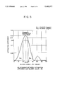
- FIG. 5 shows another graph of the diffraction light factor of the blazed diffraction grating
- FIG. 6 illustrates the blazed diffraction grating
- FIG. 7 shows a block diagram of an embodiment of a drive system having the displacement detection apparatus of the present invention.
- FIG. 1 schematically shows an embodiment of the present invention, which forms an optical encoder.
- FIG. 2A shows a front view of the encoder of FIG. 1
- FIG. 2B shows a side view of the encoder of FIG. 1
- FIG. 3 shows a blazed grating used in the encoder of FIG. 1.
- Numeral 1 denotes a light emitting element such as an LED or a laser diode
- numeral 2 denotes a folding mirror
- numeral 3 denotes a light receiving element such as a silicon photo-diode for photo-electric conversion.
- G1 denotes a blazed diffraction grating for splitting a light beam, which merely produces 0-order and +1-order diffraction lights or applies most portions of an incident light beam energy to the 0-order and +1-order diffraction lights.
- G2 denotes a diffraction grating which is a scale mounted on an object to be examined and is moved in a direction of an arrow X.
- G3 denotes a blazed diffraction grating for combining light beams, which has its blazing angle arranged symmetrically to the blazing angle of the blazed diffraction grating G1, for example as shown in FIG. 2a, to merely produce the 0-order and -1-order diffraction lights or apply most portions of the incident light beam energy to the 0-order and -1-order diffraction lights.
- Numeral 6 denotes a lens for forming a collimated light beam.
- a light beam emitted from the light emitting element 1 is folded by the folding mirror 2 and converted to a proper collimated light beam R by a lens 6, and the light beam R is transmissive diffracted by the diffraction grating G1 and is diffracted by it.
- a portion R0 (0-order diffraction light) of the light beam R passes through the diffraction grating G1 undeflected and is then diffracted at a point 02 on the reflective diffraction grating G2 formed on the scale.
- the light diffracted at point 02 is split into a +1-order reflected diffraction light R0+1 and a -1-order reflected diffraction light, which are subjected to phase modulation.
- the +1-order reflected diffraction light R0+1 is incident on to the diffraction grating G3 with a phase shift of +2 ⁇ x/P, where x is a displacement of the diffraction grating G2, and P is a pitch of the diffraction grating G2.
- the +1-order diffraction light R0+1 is transmissive diffracted by the diffraction grating G3 and split to a 0-order diffraction light, a -1-order diffracted light R0+1-1 and the like.
- -1-order diffraction light R0+1-1 is emitted perpendicularly to the plane of the diffraction grating and is then incident on the light receiving element 3.
- the phase of the wave of the -1-order diffraction light R0+1-1 is +2 ⁇ x/P.
- the +1-order diffraction light R+1 from the diffraction grating G1 is diffracted at a point 03 on the reflective grating G2, and split to the -1-order diffraction light R+1-1, +1-order diffraction light and the like, which are subject to phase modulation.
- the -1-order reflected diffraction light R+1-1 is incident on the diffraction grating G3 with a phase shift of -2 ⁇ x/P and is then incident on the diffraction grating G3.
- the 0-order diffraction light R+1-10 of the diffraction light which passes through the diffraction grating G3 undeflected has wave phase of -2 ⁇ x/P and is incident on the light receiving element 3.
- the light beams R+1-10 and R0+1-1 having their optical paths superimposed and combined by the diffraction grating G3 is converted to an interference light beam which is applied to the light receiving element 3.
- the interference phase thereof is given by;
- the blazed diffraction gratings G1 and G3 whose blazing angles are arranged symmetrically as shown in FIG. 3 are used, no extra diffraction light is produced. Consequently, the intensity of the interference light is increased and the intensity of the light incident on the photo-sensing element 3 is increased so that the contrast and the S/N ratio of the output signal are improved.
- the interference optical system is very simple in its construction, and where the lens and the diffraction gratings G1 and G3 are formed on both sides of a glass plate by a replica manufacturing method or the like, a compact and inexpensive encoder can be produced.
- the diffraction gratings which can make best use of diffraction light in which 0-order and first order are combined is required.
- the diffraction intensities I 0 and I 1 of the 0-order and 1-order light are calculated as follows assuming that the intensity of the incident light to the diffraction grating is set to be 1;
- a condition for ⁇ b in which the combined diffraction efficiency exceeds a desired permissible diffraction efficiency M is given by the following condition formula;
- FIG. 5 shows only the combined diffraction efficiency in an enlarged scale.
- I max is the maximum combined diffraction efficiency and ⁇ bmax is the blazed angle therefore.
- I 0 .8 indicates a diffraction efficiency when the combined diffraction efficiency of 0-order light is 80% of the maximum value, and ⁇ b1 and ⁇ b2 are blazed angles therefore.
- M 0.8.
- a grating having the blazed angle in the range of ⁇ b1 ⁇ b ⁇ b2 may be manufactured so that the light intensity of more than 80% of that for the maximum combined diffraction efficiency is attained.
- the range of the blazed angle ⁇ b is;
- the value of M is preferably M ⁇ 0.6, and more preferably M ⁇ 0.8.
- the present embodiment is very simple in the construction of the interference optical system and with a replica production method or the like a compact and inexpensive encoder may be attained by forming the lens and the diffraction gratings G1 and G3 on both sides of the glass plate surfaces.
- two diffraction gratings for splitting the light beam and combining the light beam are mutually symmetrical although only one of the two diffraction gratings may be a blazed grating to attain a similar effect. Further, only one of the light beam splitter and the light beam combiner is also effected by using it as a blazed grating.
- the diffraction grating G2 may be a blazed grating.
- the two blazed diffraction gratings for splitting light beam and combining light beam may not be mutually symmetric (in term of sectional shape).
- FIG. 7 shows an embodiment in which the above-mentioned present invention is applied to an encoder. It shows a system configuration of a drive system which uses the encoder.
- An encoder 101 is provided with a drive output unit of drive means 100 having a drive source such as a motor, an actuator or an engine, or a movable portion of a driven article to detect a displacement status such as a distance of movement or a displacement velocity.
- a drive source such as a motor, an actuator or an engine, or a movable portion of a driven article to detect a displacement status such as a distance of movement or a displacement velocity.
- a detection output of the encoder 101 is fed back to control means 102 which transmits a drive signal to the drive means 100 to set it as set by setting means 103.
- control means 102 which transmits a drive signal to the drive means 100 to set it as set by setting means 103.
- Such a drive system may be widely applied to an office equipment such as a typewriter, a printer, a copy machine or a facsimile machine, an image equipment such as a camera or a video apparatus, and an information recording and reproducing apparatus, a robot, a machine tool, a manufacturing equipment, a transport machine and any other apparatus having a drive means.
- office equipment such as a typewriter, a printer, a copy machine or a facsimile machine
- an image equipment such as a camera or a video apparatus
- an information recording and reproducing apparatus a robot, a machine tool, a manufacturing equipment, a transport machine and any other apparatus having a drive means.
Abstract
Description
16M/π.sup.4 ≦sin.sup.4 {F(θ.sub.b)}/{F(θ.sub.b).sup.2 G(θ.sub.b).sup.2 }
F(θ.sub.b)=πP(N-1) tan (θ.sub.b)/λ
G(θ.sub.b)=π{P(N-1) tan (θ.sub.b)/λ-1}
{+2πx/P}-{-2πx/P}=4πx/P
I.sub.0 ={sin [F(θ.sub.b)]/F(θ.sub.b)}.sup.2 F(θ.sub.b)=πP(N-1) tan [θ.sub.b ]/λI.sub.1 ={sin [G(θ.sub.b)]/G(θ.sub.b)}.sup.2 G(θ.sub.b)=π[P(N-1) tan {θ.sub.b }/λ-1]
I.sub.01 =sin.sup.4 {F(θ.sub.b)}/{F(θ.sub.b).sup.2 G(θ.sub.b).sup.2 }
θ.sub.max =tan.sup.-1 [λ/{2P(N-1)}]
I.sub.01max =16/(π.sup.4)
16M/π.sup.4 ≦sin.sup.4 {F(θ.sub.b)}/{F(θ.sub.b).sup.2 G(θ.sub.b).sup.2 }
F(θ.sub.b)=πP(N-1) tan (θ.sub.b)/λ
G(θ.sub.b)=π{P(N-1) tan (θ.sub.b)/λ-1}
19.3876°≦θ.sub.b ≦31.5886°
Claims (15)
16M/π.sup.4 ≦sin.sup.4 {F(θ.sub.b)}/{F(θ.sub.b).sup.2 G(θ.sub.b).sup.2 } F(θ.sub.b)=πP(N-1) tan (θ.sub.b)/λ[-1]
G(θ.sub.b)=π{P(N-1) tan (θ.sub.b)/λ-1} Applications Claiming Priority (2)
| Application Number | Priority Date | Filing Date | Title |
|---|---|---|---|
| JP4344560A JPH06194123A (en) | 1992-12-24 | 1992-12-24 | Displacement detecting device |
| JP4-344560 | 1992-12-24 |
Publications (1)
| Publication Number | Publication Date |
|---|---|
| US5483377A true US5483377A (en) | 1996-01-09 |
Family
ID=18370221
Family Applications (1)
| Application Number | Title | Priority Date | Filing Date |
|---|---|---|---|
| US08/169,402 Expired - Lifetime US5483377A (en) | 1992-12-24 | 1993-12-20 | Displacement detection apparatus |
Country Status (2)
| Country | Link |
|---|---|
| US (1) | US5483377A (en) |
| JP (1) | JPH06194123A (en) |
Cited By (22)
| Publication number | Priority date | Publication date | Assignee | Title |
|---|---|---|---|---|
| US5566024A (en) * | 1993-12-23 | 1996-10-15 | Xerox Corporation | Beam separation control and beam splitting by single blazed binary diffraction optical element |
| US5621527A (en) * | 1993-09-29 | 1997-04-15 | Canon Kabushiki Kaisha | Apparatus for measuring relative displacement between the apparatus and a scale which a grating is formed |
| US5637868A (en) * | 1994-03-31 | 1997-06-10 | Sony Magnescale Inc. | Fixed point detecting device using detection of light diffracted by holographic diffraction gratings |
| US5663794A (en) * | 1995-02-15 | 1997-09-02 | Canon Kabushiki Kaisha | Displacement information detection apparatus, scale used in the apparatus, and drive apparatus using the apparatus |
| US5696373A (en) * | 1994-07-28 | 1997-12-09 | Matsushita Electric Industrial Co., Ltd. | Optical encoder with dual diffraction grating |
| US5917182A (en) * | 1995-02-07 | 1999-06-29 | Canon Kabushiki Kaisha | Rotation detector and controller for detecting rotation information using a grating interference system |
| US5956140A (en) * | 1995-02-21 | 1999-09-21 | Canon Kabushiki Kaisha | Displacement detection apparatus and drive control apparatus using the same constructed to prevent collision between gratings |
| US6151185A (en) * | 1996-09-05 | 2000-11-21 | Canon Kabushiki Kaisha | Position detecting apparatus, positioning apparatus, and information recording apparatus using the same |
| WO2001027524A1 (en) * | 1999-10-14 | 2001-04-19 | Hongwei Zeng | A numerical controlled colour light source system |
| US6229140B1 (en) | 1995-10-27 | 2001-05-08 | Canon Kabushiki Kaisha | Displacement information detection apparatus |
| AU744341B2 (en) * | 1997-12-05 | 2002-02-21 | Telcordia Technologies, Inc. | Method and apparatus for variable bit rate clock recovery |
| US6424407B1 (en) | 1998-03-09 | 2002-07-23 | Otm Technologies Ltd. | Optical translation measurement |
| US6473184B1 (en) | 1999-05-10 | 2002-10-29 | Canon Kabushiki Kaisha | Interferometer which divides light beams into a plurality of beams with different optical paths |
| US6493170B1 (en) | 1998-06-08 | 2002-12-10 | Canon Kabushiki Kaisha | Interference device and position detection device using the same |
| US6570660B2 (en) | 2000-05-26 | 2003-05-27 | Canon Kabushiki Kaisha | Measuring instrument |
| US6587272B2 (en) * | 1998-06-16 | 2003-07-01 | Canon Kabushiki Kaisha | Diffractive optical element |
| US6631047B2 (en) | 1997-09-22 | 2003-10-07 | Canon Kabushiki Kaisha | Interference device, position detecting device, positioning device and information recording apparatus using the same |
| US6657181B1 (en) | 1999-03-12 | 2003-12-02 | Canon Kabushiki Kaisha | Optical element used in compact interference measuring apparatus detecting plurality of phase difference signals |
| US6674066B1 (en) | 1999-04-16 | 2004-01-06 | Canon Kabushiki Kaisha | Encoder |
| US20040007664A1 (en) * | 2002-07-08 | 2004-01-15 | Microe Systems, Inc. | Multi-track optical encoder employing beam divider |
| US6831267B2 (en) | 2000-02-15 | 2004-12-14 | Canon Kabushiki Kaisha | Optical encoder |
| US8687277B2 (en) * | 2010-08-11 | 2014-04-01 | Kenneth C. Johnson | Stacked-grating light modulator |
Families Citing this family (2)
| Publication number | Priority date | Publication date | Assignee | Title |
|---|---|---|---|---|
| DE102013222383A1 (en) * | 2013-02-06 | 2014-08-07 | Dr. Johannes Heidenhain Gmbh | Optical position measuring device |
| JP6157392B2 (en) * | 2014-03-24 | 2017-07-05 | 三菱電機株式会社 | Optical encoder |
Citations (18)
| Publication number | Priority date | Publication date | Assignee | Title |
|---|---|---|---|---|
| US4176276A (en) * | 1976-11-25 | 1979-11-27 | Ernst Leitz Wetzlar Gmbh | Photoelectric incident light distance measuring device |
| JPS59100404A (en) * | 1982-11-30 | 1984-06-09 | Ricoh Co Ltd | Reflection type triangular-shaped relief diffraction grating |
| EP0163362A1 (en) * | 1984-05-31 | 1985-12-04 | Dr. Johannes Heidenhain GmbH | Displacement measuring apparatus and method |
| WO1986003833A1 (en) * | 1984-12-22 | 1986-07-03 | Renishaw Plc | Opto-electronic scale-reading apparatus |
| EP0223009A2 (en) * | 1985-11-21 | 1987-05-27 | Dr. Johannes Heidenhain GmbH | Opto-electronic position determination device |
| WO1987007944A1 (en) * | 1986-06-21 | 1987-12-30 | Renishaw Plc | Opto-electronic scale reading apparatus |
| JPH01180615A (en) * | 1988-01-12 | 1989-07-18 | Nec Corp | Clock supply system |
| JPH02262064A (en) * | 1989-03-31 | 1990-10-24 | Canon Inc | Laser doppler speedometer |
| US5026164A (en) * | 1988-02-22 | 1991-06-25 | Mitutoyo Corporation | Optical encoder |
| EP0463561A1 (en) * | 1990-06-20 | 1992-01-02 | Canon Kabushiki Kaisha | Signal processing method and apparatus, and a system such as a displacement detecting device using the same |
| US5080465A (en) * | 1988-03-18 | 1992-01-14 | Instruments S.A. | Diffraction grating and method of making |
| GB2247313A (en) * | 1988-02-22 | 1992-02-26 | Mitutoyo Corp | Optical encoder |
| US5101102A (en) * | 1986-02-28 | 1992-03-31 | Canon Kabushiki Kaisha | Rotary encoder having a plurality of beams emitted by a diffraction grating |
| US5113067A (en) * | 1989-02-15 | 1992-05-12 | Canon Kabushiki Kaisha | Image reading apparatus having a blazed diffraction grating |
| US5216478A (en) * | 1989-03-31 | 1993-06-01 | Canon Kabushiki Kaisha | Doppler velocity meter |
| US5221835A (en) * | 1991-06-07 | 1993-06-22 | Canon Kabushiki Kaisha | Image reading apparatus having a reflective blazed diffraction grating with varied pitch |
| US5223703A (en) * | 1990-01-30 | 1993-06-29 | Canon Kabushiki Kaisha | Image reader with color decomposing blazed diffraction grating |
| US5283434A (en) * | 1991-12-20 | 1994-02-01 | Canon Kabushiki Kaisha | Displacement detecting device with integral optics |
-
1992
- 1992-12-24 JP JP4344560A patent/JPH06194123A/en active Pending
-
1993
- 1993-12-20 US US08/169,402 patent/US5483377A/en not_active Expired - Lifetime
Patent Citations (20)
| Publication number | Priority date | Publication date | Assignee | Title |
|---|---|---|---|---|
| US4176276A (en) * | 1976-11-25 | 1979-11-27 | Ernst Leitz Wetzlar Gmbh | Photoelectric incident light distance measuring device |
| JPS59100404A (en) * | 1982-11-30 | 1984-06-09 | Ricoh Co Ltd | Reflection type triangular-shaped relief diffraction grating |
| EP0163362A1 (en) * | 1984-05-31 | 1985-12-04 | Dr. Johannes Heidenhain GmbH | Displacement measuring apparatus and method |
| WO1986003833A1 (en) * | 1984-12-22 | 1986-07-03 | Renishaw Plc | Opto-electronic scale-reading apparatus |
| EP0223009A2 (en) * | 1985-11-21 | 1987-05-27 | Dr. Johannes Heidenhain GmbH | Opto-electronic position determination device |
| JPS62121314A (en) * | 1985-11-21 | 1987-06-02 | ドクトル・ヨハネス・ハイデンハイン・ゲゼルシヤフト・ミト・ベシユレンクテル・ハフツング | Photoelectric position measuring device |
| US4766310A (en) * | 1985-11-21 | 1988-08-23 | Dr. Johannes Heidenhain Gmbh | Photoelectric position measuring instrument with grids |
| US5101102A (en) * | 1986-02-28 | 1992-03-31 | Canon Kabushiki Kaisha | Rotary encoder having a plurality of beams emitted by a diffraction grating |
| WO1987007944A1 (en) * | 1986-06-21 | 1987-12-30 | Renishaw Plc | Opto-electronic scale reading apparatus |
| JPH01180615A (en) * | 1988-01-12 | 1989-07-18 | Nec Corp | Clock supply system |
| US5026164A (en) * | 1988-02-22 | 1991-06-25 | Mitutoyo Corporation | Optical encoder |
| GB2247313A (en) * | 1988-02-22 | 1992-02-26 | Mitutoyo Corp | Optical encoder |
| US5080465A (en) * | 1988-03-18 | 1992-01-14 | Instruments S.A. | Diffraction grating and method of making |
| US5113067A (en) * | 1989-02-15 | 1992-05-12 | Canon Kabushiki Kaisha | Image reading apparatus having a blazed diffraction grating |
| JPH02262064A (en) * | 1989-03-31 | 1990-10-24 | Canon Inc | Laser doppler speedometer |
| US5216478A (en) * | 1989-03-31 | 1993-06-01 | Canon Kabushiki Kaisha | Doppler velocity meter |
| US5223703A (en) * | 1990-01-30 | 1993-06-29 | Canon Kabushiki Kaisha | Image reader with color decomposing blazed diffraction grating |
| EP0463561A1 (en) * | 1990-06-20 | 1992-01-02 | Canon Kabushiki Kaisha | Signal processing method and apparatus, and a system such as a displacement detecting device using the same |
| US5221835A (en) * | 1991-06-07 | 1993-06-22 | Canon Kabushiki Kaisha | Image reading apparatus having a reflective blazed diffraction grating with varied pitch |
| US5283434A (en) * | 1991-12-20 | 1994-02-01 | Canon Kabushiki Kaisha | Displacement detecting device with integral optics |
Non-Patent Citations (4)
| Title |
|---|
| Gross et al, "Blazed Dielectric Gratings With High Beam-Coupling Efficiencies," Applied Physics Letters, vol. 36, No. 7, 1 Apr. 1980, pp. 523-525. |
| Gross et al, Blazed Dielectric Gratings With High Beam Coupling Efficiencies, Applied Physics Letters , vol. 36, No. 7, 1 Apr. 1980, pp. 523 525. * |
| Jull et al, "Perfectly Blazed Triangular Groove Reflection Gratings", J. Op. Soc. Am. A., vol. 1, No. 2, Feb. 1984, pp. 180-182. |
| Jull et al, Perfectly Blazed Triangular Groove Reflection Gratings , J. Op. Soc. Am. A., vol. 1, No. 2, Feb. 1984, pp. 180 182. * |
Cited By (33)
| Publication number | Priority date | Publication date | Assignee | Title |
|---|---|---|---|---|
| US5621527A (en) * | 1993-09-29 | 1997-04-15 | Canon Kabushiki Kaisha | Apparatus for measuring relative displacement between the apparatus and a scale which a grating is formed |
| US5566024A (en) * | 1993-12-23 | 1996-10-15 | Xerox Corporation | Beam separation control and beam splitting by single blazed binary diffraction optical element |
| US5637868A (en) * | 1994-03-31 | 1997-06-10 | Sony Magnescale Inc. | Fixed point detecting device using detection of light diffracted by holographic diffraction gratings |
| US5696373A (en) * | 1994-07-28 | 1997-12-09 | Matsushita Electric Industrial Co., Ltd. | Optical encoder with dual diffraction grating |
| US5917182A (en) * | 1995-02-07 | 1999-06-29 | Canon Kabushiki Kaisha | Rotation detector and controller for detecting rotation information using a grating interference system |
| US5663794A (en) * | 1995-02-15 | 1997-09-02 | Canon Kabushiki Kaisha | Displacement information detection apparatus, scale used in the apparatus, and drive apparatus using the apparatus |
| US5956140A (en) * | 1995-02-21 | 1999-09-21 | Canon Kabushiki Kaisha | Displacement detection apparatus and drive control apparatus using the same constructed to prevent collision between gratings |
| US6229140B1 (en) | 1995-10-27 | 2001-05-08 | Canon Kabushiki Kaisha | Displacement information detection apparatus |
| US6617572B2 (en) | 1995-10-27 | 2003-09-09 | Canon Kabushiki Kaisha | Displacement information detection apparatus |
| US6151185A (en) * | 1996-09-05 | 2000-11-21 | Canon Kabushiki Kaisha | Position detecting apparatus, positioning apparatus, and information recording apparatus using the same |
| US6631047B2 (en) | 1997-09-22 | 2003-10-07 | Canon Kabushiki Kaisha | Interference device, position detecting device, positioning device and information recording apparatus using the same |
| AU744341B2 (en) * | 1997-12-05 | 2002-02-21 | Telcordia Technologies, Inc. | Method and apparatus for variable bit rate clock recovery |
| US6424407B1 (en) | 1998-03-09 | 2002-07-23 | Otm Technologies Ltd. | Optical translation measurement |
| US6741335B2 (en) | 1998-03-09 | 2004-05-25 | Otm Technologies Ltd. | Optical translation measurement |
| US6493170B1 (en) | 1998-06-08 | 2002-12-10 | Canon Kabushiki Kaisha | Interference device and position detection device using the same |
| US6587272B2 (en) * | 1998-06-16 | 2003-07-01 | Canon Kabushiki Kaisha | Diffractive optical element |
| US20060114474A1 (en) * | 1999-03-12 | 2006-06-01 | Canon Kabushiki Kaisha | Interference measuring apparatus |
| US7375820B2 (en) | 1999-03-12 | 2008-05-20 | Canon Kabushiki Kaisha | Interference measuring apparatus for detecting a plurality of stable phase difference signals |
| US6657181B1 (en) | 1999-03-12 | 2003-12-02 | Canon Kabushiki Kaisha | Optical element used in compact interference measuring apparatus detecting plurality of phase difference signals |
| US7034947B2 (en) | 1999-03-12 | 2006-04-25 | Canon Kabushiki Kaisha | Compact interference measuring apparatus for detecting the magnitude and direction of positional deviation |
| US6674066B1 (en) | 1999-04-16 | 2004-01-06 | Canon Kabushiki Kaisha | Encoder |
| US6473184B1 (en) | 1999-05-10 | 2002-10-29 | Canon Kabushiki Kaisha | Interferometer which divides light beams into a plurality of beams with different optical paths |
| GB2384551A (en) * | 1999-10-14 | 2003-07-30 | Coloray Digital Technology | A numerical controlled colour light source system |
| US6774583B1 (en) | 1999-10-14 | 2004-08-10 | Hongwei Zeng | Numerical controlled colour light source system |
| GB2384551B (en) * | 1999-10-14 | 2004-08-25 | Coloray Digital Technology | A numerical controlled colour light source system |
| WO2001027524A1 (en) * | 1999-10-14 | 2001-04-19 | Hongwei Zeng | A numerical controlled colour light source system |
| US6831267B2 (en) | 2000-02-15 | 2004-12-14 | Canon Kabushiki Kaisha | Optical encoder |
| US20050007598A1 (en) * | 2000-02-15 | 2005-01-13 | Canon Kabushiki Kaisha | Optical encoder |
| US6999179B2 (en) | 2000-02-15 | 2006-02-14 | Canon Kabushiki Kaisha | Optical encoder |
| US6570660B2 (en) | 2000-05-26 | 2003-05-27 | Canon Kabushiki Kaisha | Measuring instrument |
| US20040007664A1 (en) * | 2002-07-08 | 2004-01-15 | Microe Systems, Inc. | Multi-track optical encoder employing beam divider |
| US7193204B2 (en) * | 2002-07-08 | 2007-03-20 | Gsi Group Corporation | Multi-track optical encoder employing beam divider |
| US8687277B2 (en) * | 2010-08-11 | 2014-04-01 | Kenneth C. Johnson | Stacked-grating light modulator |
Also Published As
| Publication number | Publication date |
|---|---|
| JPH06194123A (en) | 1994-07-15 |
Similar Documents
| Publication | Publication Date | Title |
|---|---|---|
| US5483377A (en) | Displacement detection apparatus | |
| US5680211A (en) | Apparatus for optically detecting displacement of an object using a synthesizing means utilizing a substrate with two diffraction gratings thereon | |
| US4970388A (en) | Encoder with diffraction grating and multiply diffracted light | |
| US4930895A (en) | Encoder for forming interference fringes by re-diffracted lights from an optical type scale and photoelectrically converting the interference fringes to thereby detect the displacement of the scale | |
| US5502466A (en) | Doppler velocimeter and position information detection apparatus for use with objects having variations in surface depth | |
| US4091281A (en) | Light modulation system | |
| JP3158878B2 (en) | Optical encoder | |
| US5327218A (en) | Method and apparatus for measuring displacement by using a diffracted inverted image projected on a diffraction grating | |
| JP3254737B2 (en) | encoder | |
| JPH0820275B2 (en) | Position measuring device | |
| US6407815B2 (en) | Optical displacement measurement system | |
| US6166817A (en) | Optical displacement measurement system for detecting the relative movement of a machine part | |
| EP0718601B1 (en) | Opto-electronic scale reading apparatus | |
| EP0489399B1 (en) | Displacement detector | |
| US5017777A (en) | Diffracted beam encoder | |
| JPH0827172B2 (en) | Integrated optical sensor device | |
| EP0364984B1 (en) | Interferometer using multi-mode semiconductor laser | |
| JPH06201327A (en) | Displacement detector | |
| JP2718440B2 (en) | Length measuring or angle measuring device | |
| US4879462A (en) | Opto-electronic scale-reading apparatus having spatial filter for wavelength separation | |
| WO1996006331A1 (en) | Quadrature diffractive encoder | |
| JP3038860B2 (en) | Encoder | |
| JP2718439B2 (en) | Length measuring or angle measuring device | |
| JP2670457B2 (en) | Zero position detector | |
| JP2715623B2 (en) | Encoder |
Legal Events
| Date | Code | Title | Description |
|---|---|---|---|
| AS | Assignment |
Owner name: CANON KABUSHIKI KAISHA, JAPAN Free format text: ASSIGNMENT OF ASSIGNORS INTEREST;ASSIGNORS:KANEDA, YASUSHI;ISHIZUKA, KOH;KONDO, HIROSHI;AND OTHERS;REEL/FRAME:006828/0875 Effective date: 19931216 |
|
| STCF | Information on status: patent grant |
Free format text: PATENTED CASE |
|
| CC | Certificate of correction | ||
| FPAY | Fee payment |
Year of fee payment: 4 |
|
| FEPP | Fee payment procedure |
Free format text: PAYOR NUMBER ASSIGNED (ORIGINAL EVENT CODE: ASPN); ENTITY STATUS OF PATENT OWNER: LARGE ENTITY Free format text: PAYER NUMBER DE-ASSIGNED (ORIGINAL EVENT CODE: RMPN); ENTITY STATUS OF PATENT OWNER: LARGE ENTITY |
|
| FPAY | Fee payment |
Year of fee payment: 8 |
|
| FPAY | Fee payment |
Year of fee payment: 12 |