US5490974A - Tubular heater for preparing carbon monoxide-containing gas mixtures - Google Patents
Tubular heater for preparing carbon monoxide-containing gas mixtures Download PDFInfo
- Publication number
- US5490974A US5490974A US08/281,058 US28105894A US5490974A US 5490974 A US5490974 A US 5490974A US 28105894 A US28105894 A US 28105894A US 5490974 A US5490974 A US 5490974A
- Authority
- US
- United States
- Prior art keywords
- tubes
- outlet ends
- combustion chamber
- tubular heater
- synthesis gas
- Prior art date
- Legal status (The legal status is an assumption and is not a legal conclusion. Google has not performed a legal analysis and makes no representation as to the accuracy of the status listed.)
- Expired - Lifetime
Links
Images
Classifications
-
- C—CHEMISTRY; METALLURGY
- C01—INORGANIC CHEMISTRY
- C01B—NON-METALLIC ELEMENTS; COMPOUNDS THEREOF; METALLOIDS OR COMPOUNDS THEREOF NOT COVERED BY SUBCLASS C01C
- C01B3/00—Hydrogen; Gaseous mixtures containing hydrogen; Separation of hydrogen from mixtures containing it; Purification of hydrogen
- C01B3/02—Production of hydrogen or of gaseous mixtures containing a substantial proportion of hydrogen
- C01B3/22—Production of hydrogen or of gaseous mixtures containing a substantial proportion of hydrogen by decomposition of gaseous or liquid organic compounds
- C01B3/24—Production of hydrogen or of gaseous mixtures containing a substantial proportion of hydrogen by decomposition of gaseous or liquid organic compounds of hydrocarbons
- C01B3/26—Production of hydrogen or of gaseous mixtures containing a substantial proportion of hydrogen by decomposition of gaseous or liquid organic compounds of hydrocarbons using catalysts
-
- B—PERFORMING OPERATIONS; TRANSPORTING
- B01—PHYSICAL OR CHEMICAL PROCESSES OR APPARATUS IN GENERAL
- B01J—CHEMICAL OR PHYSICAL PROCESSES, e.g. CATALYSIS OR COLLOID CHEMISTRY; THEIR RELEVANT APPARATUS
- B01J19/00—Chemical, physical or physico-chemical processes in general; Their relevant apparatus
- B01J19/14—Production of inert gas mixtures; Use of inert gases in general
-
- B—PERFORMING OPERATIONS; TRANSPORTING
- B01—PHYSICAL OR CHEMICAL PROCESSES OR APPARATUS IN GENERAL
- B01J—CHEMICAL OR PHYSICAL PROCESSES, e.g. CATALYSIS OR COLLOID CHEMISTRY; THEIR RELEVANT APPARATUS
- B01J8/00—Chemical or physical processes in general, conducted in the presence of fluids and solid particles; Apparatus for such processes
- B01J8/02—Chemical or physical processes in general, conducted in the presence of fluids and solid particles; Apparatus for such processes with stationary particles, e.g. in fixed beds
- B01J8/06—Chemical or physical processes in general, conducted in the presence of fluids and solid particles; Apparatus for such processes with stationary particles, e.g. in fixed beds in tube reactors; the solid particles being arranged in tubes
- B01J8/062—Chemical or physical processes in general, conducted in the presence of fluids and solid particles; Apparatus for such processes with stationary particles, e.g. in fixed beds in tube reactors; the solid particles being arranged in tubes being installed in a furnace
-
- C—CHEMISTRY; METALLURGY
- C01—INORGANIC CHEMISTRY
- C01B—NON-METALLIC ELEMENTS; COMPOUNDS THEREOF; METALLOIDS OR COMPOUNDS THEREOF NOT COVERED BY SUBCLASS C01C
- C01B3/00—Hydrogen; Gaseous mixtures containing hydrogen; Separation of hydrogen from mixtures containing it; Purification of hydrogen
- C01B3/02—Production of hydrogen or of gaseous mixtures containing a substantial proportion of hydrogen
- C01B3/32—Production of hydrogen or of gaseous mixtures containing a substantial proportion of hydrogen by reaction of gaseous or liquid organic compounds with gasifying agents, e.g. water, carbon dioxide, air
- C01B3/34—Production of hydrogen or of gaseous mixtures containing a substantial proportion of hydrogen by reaction of gaseous or liquid organic compounds with gasifying agents, e.g. water, carbon dioxide, air by reaction of hydrocarbons with gasifying agents
- C01B3/38—Production of hydrogen or of gaseous mixtures containing a substantial proportion of hydrogen by reaction of gaseous or liquid organic compounds with gasifying agents, e.g. water, carbon dioxide, air by reaction of hydrocarbons with gasifying agents using catalysts
- C01B3/384—Production of hydrogen or of gaseous mixtures containing a substantial proportion of hydrogen by reaction of gaseous or liquid organic compounds with gasifying agents, e.g. water, carbon dioxide, air by reaction of hydrocarbons with gasifying agents using catalysts the catalyst being continuously externally heated
-
- B—PERFORMING OPERATIONS; TRANSPORTING
- B01—PHYSICAL OR CHEMICAL PROCESSES OR APPARATUS IN GENERAL
- B01J—CHEMICAL OR PHYSICAL PROCESSES, e.g. CATALYSIS OR COLLOID CHEMISTRY; THEIR RELEVANT APPARATUS
- B01J2208/00—Processes carried out in the presence of solid particles; Reactors therefor
- B01J2208/00008—Controlling the process
- B01J2208/00017—Controlling the temperature
- B01J2208/00477—Controlling the temperature by thermal insulation means
- B01J2208/00495—Controlling the temperature by thermal insulation means using insulating materials or refractories
-
- C—CHEMISTRY; METALLURGY
- C01—INORGANIC CHEMISTRY
- C01B—NON-METALLIC ELEMENTS; COMPOUNDS THEREOF; METALLOIDS OR COMPOUNDS THEREOF NOT COVERED BY SUBCLASS C01C
- C01B2203/00—Integrated processes for the production of hydrogen or synthesis gas
- C01B2203/02—Processes for making hydrogen or synthesis gas
- C01B2203/0205—Processes for making hydrogen or synthesis gas containing a reforming step
- C01B2203/0227—Processes for making hydrogen or synthesis gas containing a reforming step containing a catalytic reforming step
- C01B2203/0233—Processes for making hydrogen or synthesis gas containing a reforming step containing a catalytic reforming step the reforming step being a steam reforming step
-
- C—CHEMISTRY; METALLURGY
- C01—INORGANIC CHEMISTRY
- C01B—NON-METALLIC ELEMENTS; COMPOUNDS THEREOF; METALLOIDS OR COMPOUNDS THEREOF NOT COVERED BY SUBCLASS C01C
- C01B2203/00—Integrated processes for the production of hydrogen or synthesis gas
- C01B2203/08—Methods of heating or cooling
- C01B2203/0805—Methods of heating the process for making hydrogen or synthesis gas
- C01B2203/0811—Methods of heating the process for making hydrogen or synthesis gas by combustion of fuel
- C01B2203/0816—Heating by flames
-
- C—CHEMISTRY; METALLURGY
- C01—INORGANIC CHEMISTRY
- C01B—NON-METALLIC ELEMENTS; COMPOUNDS THEREOF; METALLOIDS OR COMPOUNDS THEREOF NOT COVERED BY SUBCLASS C01C
- C01B2203/00—Integrated processes for the production of hydrogen or synthesis gas
- C01B2203/08—Methods of heating or cooling
- C01B2203/0805—Methods of heating the process for making hydrogen or synthesis gas
- C01B2203/0866—Methods of heating the process for making hydrogen or synthesis gas by combination of different heating methods
-
- C—CHEMISTRY; METALLURGY
- C01—INORGANIC CHEMISTRY
- C01B—NON-METALLIC ELEMENTS; COMPOUNDS THEREOF; METALLOIDS OR COMPOUNDS THEREOF NOT COVERED BY SUBCLASS C01C
- C01B2203/00—Integrated processes for the production of hydrogen or synthesis gas
- C01B2203/08—Methods of heating or cooling
- C01B2203/0872—Methods of cooling
- C01B2203/0883—Methods of cooling by indirect heat exchange
-
- C—CHEMISTRY; METALLURGY
- C01—INORGANIC CHEMISTRY
- C01B—NON-METALLIC ELEMENTS; COMPOUNDS THEREOF; METALLOIDS OR COMPOUNDS THEREOF NOT COVERED BY SUBCLASS C01C
- C01B2203/00—Integrated processes for the production of hydrogen or synthesis gas
- C01B2203/10—Catalysts for performing the hydrogen forming reactions
- C01B2203/1041—Composition of the catalyst
- C01B2203/1047—Group VIII metal catalysts
- C01B2203/1052—Nickel or cobalt catalysts
-
- C—CHEMISTRY; METALLURGY
- C01—INORGANIC CHEMISTRY
- C01B—NON-METALLIC ELEMENTS; COMPOUNDS THEREOF; METALLOIDS OR COMPOUNDS THEREOF NOT COVERED BY SUBCLASS C01C
- C01B2203/00—Integrated processes for the production of hydrogen or synthesis gas
- C01B2203/12—Feeding the process for making hydrogen or synthesis gas
- C01B2203/1205—Composition of the feed
- C01B2203/1211—Organic compounds or organic mixtures used in the process for making hydrogen or synthesis gas
- C01B2203/1235—Hydrocarbons
- C01B2203/1241—Natural gas or methane
Definitions
- This invention relates to a tubular heater for a catalytic cracking of hydrocarbons in order to prepare a raw synthesis gas, which mainly contains hydrogen, carbon monoxide and carbon dioxide, which heater comprises numerous tubes, which are disposed in a combustion chamber and contain catalyst.
- Tubular heaters of that kind are known and serve, e.g., for a catalytic cracking of natural gas to prepare a synthesis gas, which is used, e.g., for the synthesis of methanol.
- Pressures in the range From 1 to 20 bars are usually maintained in the tubes, and the raw synthesis gas has temperatures between 700° and 1000° C. at the outlet end of the tubes. It has been found that the outlet end of the tube is subjected to a corrosive action which results in the formation of carbides (metal dusting) and by which the metallic material is destroyed.
- a tubular heater which is of the kind described first hereinbefore this is accomplished in accordance with the invention in that means are provided for supplying a gaseous or vaporous protecting fluid which is substantially free of CO to the outside surface of the outlet ends of at least some of the tubes, which outlet ends are disposed outside the combustion chamber and flown through by raw synthesis gas. That protecting fluid prevents a corrosive action of the CO-containing synthesis gas in the particularly susceptible region around the outlet ends of the tunes.
- the temperature region in which metal dusting corrosion can take place is between about 500° and 850° C.
- At least some of the tubes are preferably provided on the outside of their outlet end with a chamber for receiving a protecting fluid. That chamber usually adjoins a refractory lining, which surrounds the outlet end of the tubes.
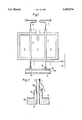
- FIG. 1 is a schematic horizontal sectional view showing a tubular heater
- FIG. 2 is a longitudinal sectional view which shows on a larger scale the outlet end of a tube.
- a refractory housing 1 contains a combustion chamber 2, in which numerous vertical tubes 3 are heated from the outside. Heating is effected by a plurality of burners 4, which are supplied, e.g., with natural gas. A mixture which contains hydrocarbons and steam is supplied through supply lines 5 into the tubes 3 and is reacted in the tubes on the catalyst provided therein and consisting, e.g., of a nickel catalyst. A raw synthesis is thus prepared, which mainly contains hydrogen, carbon monoxide, and carbon dioxide. At temperatures from 700° to 1000° C. and preferably of at least 800° C. the synthesis gas flows downwardly in the tubes and exits through the outlet ends 3a into a collecting line 6.
- carbides are formed by the decomposition of carbon monoxide by the reaction 2 CO ⁇ CO 2 +C, which is particularly intense at temperatures in the range from 500° to 850° C. Temperatures in that range usually occur on the outside surface of the outlet ends 3a and in their environment.
- the collecting line 6 is provided on its side surface with a refractory lining 6a, which surrounds also the outlet ends 3a of the tubes 3. Becausethe refractory lining has a certain porosity, synthesis gas must be expected to diffuse through the refractory lining and synthesis gas at relatively low temperatures reaches the outside surface of the outlet ends3a so that the above-mentioned corrosion takes place.
- each outlet end is provided with a supply line 7, through which a gaseous or vaporous protecting fluid is supplied from a main line 8.
- the protecting fluid may consist, e.g., of hydrogen, water vapor, nitrogen or CO 2 .
- FIG. 2 how the protecting fluid is conducted through the line 7 into a chamber 9, which is disposed within a bell-shaped enlarged portion 10 of the collecting line 6.
- the enlarged portion 10 is welded at its top end 10a to the tube 3.
- the protecting fluid prevents themetal dusting corrosion on the outside surface of the outlet end 3a and on the inside surface of the enlarged portion 10.
- the refractory lining 6a of the collecting line 6 surrounds the outlet end 3a of the tube 3.
- the lining 6a consists, e.g., of a rammed composition and is slightly porous so that the protecting fluid can diffuse out of thechamber 9 through the lining and is finally discharged in the collecting line 6 together with the synthesis gas.
- the line 7 which comes from the main line8 and conducts protecting fluid extends downwardly over a certain distance in contact with the outside surface of the associated tube 3 so that the hot gas inside the tube 3 is used to heat the protecting fluid in the line7 by an indirect heat exchange and the protecting fluid is at an elevated temperature as it enters the chamber 9. That heating of the protecting fluid prevents thermal stresses adjacent to the outlet end 3a.
Abstract
Description
Claims (7)
Applications Claiming Priority (2)
| Application Number | Priority Date | Filing Date | Title |
|---|---|---|---|
| DE4327176.6 | 1993-08-13 | ||
| DE4327176A DE4327176C1 (en) | 1993-08-13 | 1993-08-13 | Tube furnace for the production of gas mixtures containing carbon monoxide |
Publications (1)
| Publication Number | Publication Date |
|---|---|
| US5490974A true US5490974A (en) | 1996-02-13 |
Family
ID=6495082
Family Applications (1)
| Application Number | Title | Priority Date | Filing Date |
|---|---|---|---|
| US08/281,058 Expired - Lifetime US5490974A (en) | 1993-08-13 | 1994-07-27 | Tubular heater for preparing carbon monoxide-containing gas mixtures |
Country Status (14)
| Country | Link |
|---|---|
| US (1) | US5490974A (en) |
| EP (1) | EP0638514B1 (en) |
| CN (1) | CN1037504C (en) |
| AT (1) | ATE151056T1 (en) |
| AU (1) | AU673273B2 (en) |
| CA (1) | CA2129303C (en) |
| DE (2) | DE4327176C1 (en) |
| DK (1) | DK0638514T3 (en) |
| ES (1) | ES2102104T3 (en) |
| MY (1) | MY124300A (en) |
| NZ (1) | NZ260957A (en) |
| RU (1) | RU2102310C1 (en) |
| SA (1) | SA94140510B1 (en) |
| ZA (1) | ZA946084B (en) |
Cited By (7)
| Publication number | Priority date | Publication date | Assignee | Title |
|---|---|---|---|---|
| EP0799639A1 (en) | 1996-04-06 | 1997-10-08 | Metallgesellschaft Aktiengesellschaft | Metallic surface having a heat-insulating layer, protected against metal-dusting corrosion |
| AU694596B2 (en) * | 1995-01-28 | 1998-07-23 | Metallgesellschaft Aktiengesellschaft | Method and apparatus for conducting a carbon monoxide- containing hot gas mixture |
| AU713896B2 (en) * | 1994-09-08 | 1999-12-16 | Metallgesellschaft Aktiengesellschaft | Hot gas line for gases containing hydrogen and carbon monoxide |
| US20100129269A1 (en) * | 2006-11-08 | 2010-05-27 | Uhde Gmbh | Collecting main for tubular cracking furnaces |
| CN101443106B (en) * | 2006-05-15 | 2012-05-09 | 犹德有限公司 | Collecting line for tubular reforming furnaces |
| WO2018152052A1 (en) | 2017-02-15 | 2018-08-23 | Praxair Technology, Inc. | Steam methane reformer tube outlet assembly |
| WO2019199521A1 (en) | 2018-04-10 | 2019-10-17 | Praxair Technology, Inc. | Steam methane reformer tube outlet assembly |
Families Citing this family (5)
| Publication number | Priority date | Publication date | Assignee | Title |
|---|---|---|---|---|
| EP0765867A1 (en) * | 1995-09-27 | 1997-04-02 | Hoechst Aktiengesellschaft | Substituted benzoyl guanidines, process for their preparation, their use as antiarrhythmics or diagnostic agent as well as pharmaceuticals containing them |
| ATE556987T1 (en) * | 2000-03-22 | 2012-05-15 | Ammonia Casale Sa | METHOD FOR HYDROCARBON REFORMING |
| DE10142794A1 (en) * | 2001-08-31 | 2003-03-20 | Ballard Power Systems | Catalytic coating for a gas generating unit |
| DE102012015667A1 (en) * | 2012-08-09 | 2014-04-30 | L'Air Liquide, Société Anonyme pour l'Etude et l'Exploitation des Procédés Georges Claude | Discharge system for a steam reformer and storage for this |
| US9862602B1 (en) * | 2017-03-27 | 2018-01-09 | Lyten, Inc. | Cracking of a process gas |
Citations (14)
| Publication number | Priority date | Publication date | Assignee | Title |
|---|---|---|---|---|
| US2915367A (en) * | 1956-04-27 | 1959-12-01 | Du Pont | Metal oxide production |
| DE1542160A1 (en) * | 1964-06-25 | 1970-07-02 | Girdler Corp | Reforming furnace or the like. made of standardized components |
| US3607125A (en) * | 1968-12-30 | 1971-09-21 | Gen Electric | Reformer tube construction |
| US3897471A (en) * | 1969-06-18 | 1975-07-29 | Metallgesellschaft Ag | Process for producing methanol |
| US4324649A (en) * | 1980-07-08 | 1982-04-13 | Pullman Incorporated | Fired process heater |
| US4336229A (en) * | 1979-11-29 | 1982-06-22 | Didier Engineering Gmbh | Apparatus for the production of ammonia synthesis gas from purified coke oven gas |
| EP0171583A2 (en) * | 1984-08-10 | 1986-02-19 | Uhde GmbH | Tubular reaction system for a tubular cracking furnace |
| EP0258907A2 (en) * | 1986-09-05 | 1988-03-09 | Kubota Corporation | Reactor tube for thermally cracking of reforming hydrocarbons |
| US4830091A (en) * | 1984-04-28 | 1989-05-16 | Basf Aktiengesellschaft | Method of removing heat from a vertical steam reformer connecting pipe |
| US4853190A (en) * | 1983-03-16 | 1989-08-01 | Degussa Ag | Process & apparatus for the production of hydrogen cyanide |
| US4999089A (en) * | 1988-09-30 | 1991-03-12 | Mitsui Engineering & Shipbuilidng Co., Ltd. | Cracking furnace |
| US5283049A (en) * | 1992-06-18 | 1994-02-01 | Quantum Chemical Corporation | Minimizing coking problems in tubular process furnaces |
| US5362453A (en) * | 1992-07-03 | 1994-11-08 | Uhde Gmbh | Reformer for the generation of synthesis gas |
| US5399321A (en) * | 1990-04-13 | 1995-03-21 | Compagnie Francaise D'etudes Et De Construction Technip | Tubular pressurized catalytic hydrocarbon converter |
-
1993
- 1993-08-13 DE DE4327176A patent/DE4327176C1/en not_active Expired - Lifetime
- 1993-12-09 MY MYPI93002647A patent/MY124300A/en unknown
-
1994
- 1994-01-19 SA SA94140510A patent/SA94140510B1/en unknown
- 1994-07-06 AT AT94110499T patent/ATE151056T1/en active
- 1994-07-06 ES ES94110499T patent/ES2102104T3/en not_active Expired - Lifetime
- 1994-07-06 DK DK94110499.4T patent/DK0638514T3/en active
- 1994-07-06 DE DE59402287T patent/DE59402287D1/en not_active Expired - Lifetime
- 1994-07-06 EP EP94110499A patent/EP0638514B1/en not_active Expired - Lifetime
- 1994-07-07 NZ NZ260957A patent/NZ260957A/en not_active IP Right Cessation
- 1994-07-27 CN CN94107964A patent/CN1037504C/en not_active Expired - Lifetime
- 1994-07-27 US US08/281,058 patent/US5490974A/en not_active Expired - Lifetime
- 1994-08-02 CA CA002129303A patent/CA2129303C/en not_active Expired - Lifetime
- 1994-08-11 AU AU70222/94A patent/AU673273B2/en not_active Expired
- 1994-08-12 ZA ZA946084A patent/ZA946084B/en unknown
- 1994-08-12 RU RU94038428A patent/RU2102310C1/en active
Patent Citations (15)
| Publication number | Priority date | Publication date | Assignee | Title |
|---|---|---|---|---|
| US2915367A (en) * | 1956-04-27 | 1959-12-01 | Du Pont | Metal oxide production |
| DE1542160A1 (en) * | 1964-06-25 | 1970-07-02 | Girdler Corp | Reforming furnace or the like. made of standardized components |
| US3607125A (en) * | 1968-12-30 | 1971-09-21 | Gen Electric | Reformer tube construction |
| US3897471A (en) * | 1969-06-18 | 1975-07-29 | Metallgesellschaft Ag | Process for producing methanol |
| US4336229A (en) * | 1979-11-29 | 1982-06-22 | Didier Engineering Gmbh | Apparatus for the production of ammonia synthesis gas from purified coke oven gas |
| US4324649A (en) * | 1980-07-08 | 1982-04-13 | Pullman Incorporated | Fired process heater |
| US4853190A (en) * | 1983-03-16 | 1989-08-01 | Degussa Ag | Process & apparatus for the production of hydrogen cyanide |
| US4830091A (en) * | 1984-04-28 | 1989-05-16 | Basf Aktiengesellschaft | Method of removing heat from a vertical steam reformer connecting pipe |
| US4647436A (en) * | 1984-08-10 | 1987-03-03 | Uhde Gmbh | Reaction tube system for a steam reformer |
| EP0171583A2 (en) * | 1984-08-10 | 1986-02-19 | Uhde GmbH | Tubular reaction system for a tubular cracking furnace |
| EP0258907A2 (en) * | 1986-09-05 | 1988-03-09 | Kubota Corporation | Reactor tube for thermally cracking of reforming hydrocarbons |
| US4999089A (en) * | 1988-09-30 | 1991-03-12 | Mitsui Engineering & Shipbuilidng Co., Ltd. | Cracking furnace |
| US5399321A (en) * | 1990-04-13 | 1995-03-21 | Compagnie Francaise D'etudes Et De Construction Technip | Tubular pressurized catalytic hydrocarbon converter |
| US5283049A (en) * | 1992-06-18 | 1994-02-01 | Quantum Chemical Corporation | Minimizing coking problems in tubular process furnaces |
| US5362453A (en) * | 1992-07-03 | 1994-11-08 | Uhde Gmbh | Reformer for the generation of synthesis gas |
Non-Patent Citations (10)
| Title |
|---|
| Chemical Engineering, vol. 93, No. 1, pp. 83 87, Jan. 6, 1986. * |
| Chemical Engineering, vol. 93, No. 1, pp. 83-87, Jan. 6, 1986. |
| Hydrocarbon Processing, vol. 51, No. 8, pp. 73 75, Aug. 1972. * |
| Hydrocarbon Processing, vol. 51, No. 8, pp. 73-75, Aug. 1972. |
| Karl Liebknecht, Spezifische Probleme bei der Entwicklung, Projektierung und Inbetriebnahme von R hren fen f r die petrolchemische Industrie, Chem. Techn., 21, Jg., Heft 12, pp. 766 769, Dec. 1969. * |
| Karl Liebknecht, Spezifische Probleme bei der Entwicklung, Projektierung und Inbetriebnahme von Rohrenofen fur die petrolchemische Industrie, Chem. Techn., 21, Jg., Heft 12, pp. 766-769, Dec. 1969. |
| Norman E. Hamner, Proceedings of the Fourth International Congress on Metallic Corrosion, pp. 258 263, 1972. * |
| Norman E. Hamner, Proceedings of the Fourth International Congress on Metallic Corrosion, pp. 258-263, 1972. |
| R. F. Hochman, Basic Studies of Metal Deterioration ( Metal Dusting ) in Carbonaceous Environments at Elevated Temperatures, pp. 258 263, 1969. * |
| R. F. Hochman, Basic Studies of Metal Deterioration ("Metal Dusting") in Carbonaceous Environments at Elevated Temperatures, pp. 258-263, 1969. |
Cited By (10)
| Publication number | Priority date | Publication date | Assignee | Title |
|---|---|---|---|---|
| AU713896B2 (en) * | 1994-09-08 | 1999-12-16 | Metallgesellschaft Aktiengesellschaft | Hot gas line for gases containing hydrogen and carbon monoxide |
| AU694596B2 (en) * | 1995-01-28 | 1998-07-23 | Metallgesellschaft Aktiengesellschaft | Method and apparatus for conducting a carbon monoxide- containing hot gas mixture |
| US5935517A (en) * | 1995-01-28 | 1999-08-10 | Metallgesellschaft Ag | Method of preventing metal dusting corrosion of ducts which conduct hot gas mixtures containing carbon monoxide |
| EP0799639A1 (en) | 1996-04-06 | 1997-10-08 | Metallgesellschaft Aktiengesellschaft | Metallic surface having a heat-insulating layer, protected against metal-dusting corrosion |
| CN101443106B (en) * | 2006-05-15 | 2012-05-09 | 犹德有限公司 | Collecting line for tubular reforming furnaces |
| US20100129269A1 (en) * | 2006-11-08 | 2010-05-27 | Uhde Gmbh | Collecting main for tubular cracking furnaces |
| US8236252B2 (en) * | 2006-11-08 | 2012-08-07 | Uhde Gmbh | Collecting main for tubular cracking furnaces |
| WO2018152052A1 (en) | 2017-02-15 | 2018-08-23 | Praxair Technology, Inc. | Steam methane reformer tube outlet assembly |
| US10384183B2 (en) | 2017-02-15 | 2019-08-20 | Praxair Technology, Inc. | Steam methane reformer tube outlet assembly |
| WO2019199521A1 (en) | 2018-04-10 | 2019-10-17 | Praxair Technology, Inc. | Steam methane reformer tube outlet assembly |
Also Published As
| Publication number | Publication date |
|---|---|
| RU94038428A (en) | 1996-06-10 |
| ATE151056T1 (en) | 1997-04-15 |
| EP0638514A1 (en) | 1995-02-15 |
| CN1098699A (en) | 1995-02-15 |
| EP0638514B1 (en) | 1997-04-02 |
| CA2129303C (en) | 2003-12-09 |
| DE4327176C1 (en) | 1995-01-26 |
| ZA946084B (en) | 1996-02-12 |
| MY124300A (en) | 2006-06-30 |
| CN1037504C (en) | 1998-02-25 |
| ES2102104T3 (en) | 1997-07-16 |
| AU673273B2 (en) | 1996-10-31 |
| NZ260957A (en) | 1995-09-26 |
| DK0638514T3 (en) | 1997-04-21 |
| DE59402287D1 (en) | 1997-05-07 |
| SA94140510B1 (en) | 2005-05-04 |
| RU2102310C1 (en) | 1998-01-20 |
| AU7022294A (en) | 1995-02-23 |
| CA2129303A1 (en) | 1995-02-14 |
Similar Documents
| Publication | Publication Date | Title |
|---|---|---|
| US5490974A (en) | Tubular heater for preparing carbon monoxide-containing gas mixtures | |
| CA2165449C (en) | Endothermic reaction apparatus and method | |
| CA1078615A (en) | Convective power reformer equipment and system | |
| US7504048B2 (en) | Axial convective reformer | |
| JPS61222903A (en) | Manufacture of gas flow containing hydrogen and carbon oxides and apparatus therefor | |
| NZ280872A (en) | Hot gas line system for conducting co2 containing hot gas mixture: co free protective fluid supplied to system | |
| US6153152A (en) | Endothermic reaction apparatus and method | |
| CA1334247C (en) | Internal gas generator for heat treating furnace | |
| EP0247384B1 (en) | Reformer | |
| US5019356A (en) | Steam reformer with internal heat recovery | |
| US6099922A (en) | Thermally insulated metal surface protected against metal dusting corrosion | |
| US4854943A (en) | Process of producing a gas which is rich in carbon monoxide by a cracking of hydrocarbons | |
| JPH05269369A (en) | Endothermic reaction process | |
| CA3053359C (en) | Steam methane reformer tube outlet assembly | |
| JP4179717B2 (en) | Combustion method of hydrocarbon fuel by burner | |
| CA2157748C (en) | Hot gas line for gases containing hydrogen and carbon monoxide | |
| JPS649358B2 (en) | ||
| TH38617B (en) | Methods and systems for recovering energy from carbon-containing materials. | |
| PL183636B1 (en) | Method of and reactor for generating a synthesis gas in particular for organic synthesis processes used in production of methyl alcohol or ammonia | |
| TH53165A (en) | Methods and systems for recovering energy from carbon-containing materials. |
Legal Events
| Date | Code | Title | Description |
|---|---|---|---|
| AS | Assignment |
Owner name: METALLGESELLSCHAFT AKTIENGESELLSCHAFT, GERMANY Free format text: ASSIGNMENT OF ASSIGNORS INTEREST;ASSIGNORS:HOHMANN, FRIEDRICH;ROLL, WERNER;MORTEL, HANS GUNTER;REEL/FRAME:007186/0888 Effective date: 19941017 |
|
| FEPP | Fee payment procedure |
Free format text: PAYOR NUMBER ASSIGNED (ORIGINAL EVENT CODE: ASPN); ENTITY STATUS OF PATENT OWNER: LARGE ENTITY |
|
| STCF | Information on status: patent grant |
Free format text: PATENTED CASE |
|
| FEPP | Fee payment procedure |
Free format text: PAYER NUMBER DE-ASSIGNED (ORIGINAL EVENT CODE: RMPN); ENTITY STATUS OF PATENT OWNER: LARGE ENTITY |
|
| FEPP | Fee payment procedure |
Free format text: PAYOR NUMBER ASSIGNED (ORIGINAL EVENT CODE: ASPN); ENTITY STATUS OF PATENT OWNER: LARGE ENTITY |
|
| FPAY | Fee payment |
Year of fee payment: 4 |
|
| FPAY | Fee payment |
Year of fee payment: 8 |
|
| FPAY | Fee payment |
Year of fee payment: 12 |