US5507770A - Intraluminal grafting stent and method for implanting same in a blood vessel - Google Patents
Intraluminal grafting stent and method for implanting same in a blood vessel Download PDFInfo
- Publication number
- US5507770A US5507770A US08/344,120 US34412094A US5507770A US 5507770 A US5507770 A US 5507770A US 34412094 A US34412094 A US 34412094A US 5507770 A US5507770 A US 5507770A
- Authority
- US
- United States
- Prior art keywords
- wall
- composite material
- grafting stent
- blood vessel
- reagent
- Prior art date
- Legal status (The legal status is an assumption and is not a legal conclusion. Google has not performed a legal analysis and makes no representation as to the accuracy of the status listed.)
- Expired - Lifetime
Links
Images


Classifications
-
- A—HUMAN NECESSITIES
- A61—MEDICAL OR VETERINARY SCIENCE; HYGIENE
- A61F—FILTERS IMPLANTABLE INTO BLOOD VESSELS; PROSTHESES; DEVICES PROVIDING PATENCY TO, OR PREVENTING COLLAPSING OF, TUBULAR STRUCTURES OF THE BODY, e.g. STENTS; ORTHOPAEDIC, NURSING OR CONTRACEPTIVE DEVICES; FOMENTATION; TREATMENT OR PROTECTION OF EYES OR EARS; BANDAGES, DRESSINGS OR ABSORBENT PADS; FIRST-AID KITS
- A61F2/00—Filters implantable into blood vessels; Prostheses, i.e. artificial substitutes or replacements for parts of the body; Appliances for connecting them with the body; Devices providing patency to, or preventing collapsing of, tubular structures of the body, e.g. stents
- A61F2/82—Devices providing patency to, or preventing collapsing of, tubular structures of the body, e.g. stents
-
- A—HUMAN NECESSITIES
- A61—MEDICAL OR VETERINARY SCIENCE; HYGIENE
- A61F—FILTERS IMPLANTABLE INTO BLOOD VESSELS; PROSTHESES; DEVICES PROVIDING PATENCY TO, OR PREVENTING COLLAPSING OF, TUBULAR STRUCTURES OF THE BODY, e.g. STENTS; ORTHOPAEDIC, NURSING OR CONTRACEPTIVE DEVICES; FOMENTATION; TREATMENT OR PROTECTION OF EYES OR EARS; BANDAGES, DRESSINGS OR ABSORBENT PADS; FIRST-AID KITS
- A61F2/00—Filters implantable into blood vessels; Prostheses, i.e. artificial substitutes or replacements for parts of the body; Appliances for connecting them with the body; Devices providing patency to, or preventing collapsing of, tubular structures of the body, e.g. stents
- A61F2/02—Prostheses implantable into the body
- A61F2/04—Hollow or tubular parts of organs, e.g. bladders, tracheae, bronchi or bile ducts
- A61F2/06—Blood vessels
- A61F2/07—Stent-grafts
-
- A—HUMAN NECESSITIES
- A61—MEDICAL OR VETERINARY SCIENCE; HYGIENE
- A61F—FILTERS IMPLANTABLE INTO BLOOD VESSELS; PROSTHESES; DEVICES PROVIDING PATENCY TO, OR PREVENTING COLLAPSING OF, TUBULAR STRUCTURES OF THE BODY, e.g. STENTS; ORTHOPAEDIC, NURSING OR CONTRACEPTIVE DEVICES; FOMENTATION; TREATMENT OR PROTECTION OF EYES OR EARS; BANDAGES, DRESSINGS OR ABSORBENT PADS; FIRST-AID KITS
- A61F2/00—Filters implantable into blood vessels; Prostheses, i.e. artificial substitutes or replacements for parts of the body; Appliances for connecting them with the body; Devices providing patency to, or preventing collapsing of, tubular structures of the body, e.g. stents
- A61F2/82—Devices providing patency to, or preventing collapsing of, tubular structures of the body, e.g. stents
- A61F2/94—Stents retaining their form, i.e. not being deformable, after placement in the predetermined place
- A61F2/945—Stents retaining their form, i.e. not being deformable, after placement in the predetermined place hardenable, e.g. stents formed in situ
-
- A—HUMAN NECESSITIES
- A61—MEDICAL OR VETERINARY SCIENCE; HYGIENE
- A61F—FILTERS IMPLANTABLE INTO BLOOD VESSELS; PROSTHESES; DEVICES PROVIDING PATENCY TO, OR PREVENTING COLLAPSING OF, TUBULAR STRUCTURES OF THE BODY, e.g. STENTS; ORTHOPAEDIC, NURSING OR CONTRACEPTIVE DEVICES; FOMENTATION; TREATMENT OR PROTECTION OF EYES OR EARS; BANDAGES, DRESSINGS OR ABSORBENT PADS; FIRST-AID KITS
- A61F2/00—Filters implantable into blood vessels; Prostheses, i.e. artificial substitutes or replacements for parts of the body; Appliances for connecting them with the body; Devices providing patency to, or preventing collapsing of, tubular structures of the body, e.g. stents
- A61F2/95—Instruments specially adapted for placement or removal of stents or stent-grafts
- A61F2/958—Inflatable balloons for placing stents or stent-grafts
-
- A—HUMAN NECESSITIES
- A61—MEDICAL OR VETERINARY SCIENCE; HYGIENE
- A61F—FILTERS IMPLANTABLE INTO BLOOD VESSELS; PROSTHESES; DEVICES PROVIDING PATENCY TO, OR PREVENTING COLLAPSING OF, TUBULAR STRUCTURES OF THE BODY, e.g. STENTS; ORTHOPAEDIC, NURSING OR CONTRACEPTIVE DEVICES; FOMENTATION; TREATMENT OR PROTECTION OF EYES OR EARS; BANDAGES, DRESSINGS OR ABSORBENT PADS; FIRST-AID KITS
- A61F2/00—Filters implantable into blood vessels; Prostheses, i.e. artificial substitutes or replacements for parts of the body; Appliances for connecting them with the body; Devices providing patency to, or preventing collapsing of, tubular structures of the body, e.g. stents
- A61F2/02—Prostheses implantable into the body
- A61F2/04—Hollow or tubular parts of organs, e.g. bladders, tracheae, bronchi or bile ducts
- A61F2/06—Blood vessels
-
- A—HUMAN NECESSITIES
- A61—MEDICAL OR VETERINARY SCIENCE; HYGIENE
- A61F—FILTERS IMPLANTABLE INTO BLOOD VESSELS; PROSTHESES; DEVICES PROVIDING PATENCY TO, OR PREVENTING COLLAPSING OF, TUBULAR STRUCTURES OF THE BODY, e.g. STENTS; ORTHOPAEDIC, NURSING OR CONTRACEPTIVE DEVICES; FOMENTATION; TREATMENT OR PROTECTION OF EYES OR EARS; BANDAGES, DRESSINGS OR ABSORBENT PADS; FIRST-AID KITS
- A61F2/00—Filters implantable into blood vessels; Prostheses, i.e. artificial substitutes or replacements for parts of the body; Appliances for connecting them with the body; Devices providing patency to, or preventing collapsing of, tubular structures of the body, e.g. stents
- A61F2/82—Devices providing patency to, or preventing collapsing of, tubular structures of the body, e.g. stents
- A61F2/86—Stents in a form characterised by the wire-like elements; Stents in the form characterised by a net-like or mesh-like structure
- A61F2/90—Stents in a form characterised by the wire-like elements; Stents in the form characterised by a net-like or mesh-like structure characterised by a net-like or mesh-like structure
-
- A—HUMAN NECESSITIES
- A61—MEDICAL OR VETERINARY SCIENCE; HYGIENE
- A61F—FILTERS IMPLANTABLE INTO BLOOD VESSELS; PROSTHESES; DEVICES PROVIDING PATENCY TO, OR PREVENTING COLLAPSING OF, TUBULAR STRUCTURES OF THE BODY, e.g. STENTS; ORTHOPAEDIC, NURSING OR CONTRACEPTIVE DEVICES; FOMENTATION; TREATMENT OR PROTECTION OF EYES OR EARS; BANDAGES, DRESSINGS OR ABSORBENT PADS; FIRST-AID KITS
- A61F2230/00—Geometry of prostheses classified in groups A61F2/00 - A61F2/26 or A61F2/82 or A61F9/00 or A61F11/00 or subgroups thereof
- A61F2230/0002—Two-dimensional shapes, e.g. cross-sections
- A61F2230/0028—Shapes in the form of latin or greek characters
- A61F2230/0058—X-shaped
Definitions
- the present invention is directed to an intraluminal grafting stent. More specifically, the present invention is directed to an intraluminal grafting stent that can be implanted in a blood vessel at the site of aortic aneurysms. It can also provide support for diseased blood vessels.
- Intraluminal support devices are known in the art.
- an intraluminal graft/stent is disclosed in U.S. Pat. No. 5,156,620, which is incorporated herein by reference.
- the present invention is directed to an intraluminal grafting stent.
- the grafting stent includes a collapsible tube member having a first end and a second end. An outer wall and an inner wall extend between the ends. A first end wall and a second end wall extend between the outer wall and the inner wall. The outer, inner, first end and second end walls form a chamber.
- a permeable film layer extends between the first end wall and the second end wall in the chamber.
- the film layer, outer wall and end walls define a space.
- a composite material is positioned in the chamber between the inner wall and the permeable film layer.
- An opening is positioned in one of the end walls to allow the introduction of a reagent into the defined space.
- the reagent reacts with the composite material to cause the composite material to harden after the intraluminal grafting stent has been positioned in a blood vessel.
- the present invention is further directed to a method for implanting an intraluminal grafting stent in a blood vessel.
- the steps are as follows:
- an expandable catheter in an intraluminal grafting stent comprised of a collapsible tube member having a first end and a second end, an outer wall and an inner wall extending between the ends, a first end wall and a second end wall extending between the outer wall and an inner wall, the outer, inner, first end and second end walls forming a chamber, one of the end walls defining an opening, the chamber containing a composite material, the catheter being adjacent to the inner wall;
- the primary object of the present invention is to provide a superior intraluminal grafting stent and method of implantation that is effective in the repair of blood vessels.
- An important object of the present invention is to provide an intraluminal grafting stent that is relatively easy to use.
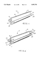
- FIG. 1 is a perspective view of the intraluminal grafting stent according to the present invention in a collapsed condition
- FIG. 2 is a perspective view similar to the view of FIG. 1 with a collapsible catheter positioned in the grafting stent;
- FIG. 3 is a cross-sectional view taken along line 3--3 of FIG. 2 showing the grafting stent positioned at the implantation site of the blood vessel with an injection device for the reagent positioned in the opening of the side wall;
- FIG. 4 is a cross-sectional view similar to the view of FIG. 3 showing the grafting stent being expanded by the catheter;
- FIG. 5 is a cross-sectional view similar to the view of FIG. 4 showing the reagent being injected into the chamber;
- FIG. 6 is a cross-sectional view similar to the view of FIG. 5 showing the grafting stent implanted in the blood vessel.
- the intraluminal grafting stent 10 includes a collapsible tube member 12.
- the tube member 12 includes a first end 14 and a second end 16.
- An outer wall 18 and an inner wall 20 extend between the ends 14 and 16.
- the inner wall 20 defines a hollow space.
- a first end wall 22 and a second end wall 24 extend between the outer wall 18 and the inner wall 20.
- the walls 18, 20, 22 and 24 of the tube member 12 are formed of a flexible, semi-rigid polymer material such as polytetrafluoroethylene or some other suitable biocompatible material.
- the tube member 12 in its collapsed condition can be formed in a "clover-leaf" cross-sectional shape. It has been found that this shape allows the intraluminal grafting stent 10 to be manipulated easily in a blood vessel. It should be understood, however, that the tube member 12 can be formed in a variety of shapes.
- a permeable film layer 30 extends between the first end wall 22 and the second end wall 24 in the chamber 26.
- the film layer 30, the outer wall 18, the first end wall 22 and the second end wall 24 define a variable space 32 in the chamber 30.
- the permeable film layer 30 can be made of a skived, blown or drawn layer of polyethylene, polyurethane, synthetic resin polymers and products, or other suitable polymer material having apertures or micropores.
- An example of a material that can be used in the construction of the film layer 30 is a microporus polymer material coated with a material such as expanded polyetrafluoroethylene (ePTFE) sold under the trademark GORETEX®.
- ePTFE expanded polyetrafluoroethylene
- a composite material 34 is positioned in the chamber 26 between the inner wall 20 and the permeable film layer 30.
- the composite material can consist of a suitable material that can be hardened, as described below, to implant the grafting stent 10 in a blood vessel 36.
- An example of a suitable composite material is an epoxy resin, such as one sold under the designation "568 B" by Aremco Products of Ossining, N.Y.
- Another example of a suitable composite material is a thermosetting polymer material.
- suitable polymer materials are a polyurethane material sold under the trademark PLURACOL P® and a silicon material sold under the trademark SILASTIC®.
- the composite material 34 can be used with or without fiber reinforcement. If fibers are used, they can be drawn-fiber glass or other high modulus fiber woven into a fabric sheath.
- the intraluminal grafting stent 10 includes an opening 40 between the defined space 32 and the exterior of the grafting stent.
- the opening 40 includes a one-way valve 42, such as a check valve, to receive an injection device 44.
- the one-way valve 42 allows materials to enter through the opening 40 into the chamber 26 but prevents the materials from escaping through the opening 40.
- an expandable catheter 50 is positioned within the collapsible tube member 12.
- the catheter 50 is expanded to cause the tube member 12 to expand at the site of implantation in the blood vessel.
- a reagent 60 is introduced through opening 40 into the defined space 32.
- the reagent can be a polymerizing agent that can react with the particular composite material 34 to cause the material to harden.
- the type of reagent used depends on the type of composite material 34 used in the grafting stent 10. For example, a reagent sold under the designation "568 A" reacts with the above-described epoxy resin.
- the polyurethane polymer material reacts with a weak acid salt catalyst.
- the silicon polymer material reacts with a platinum hydrosiliation catalyst. It will be readily apparent to one skilled in the art that many types of composite materials and reagents can be used in the present invention depending on the application.
- the reagent 60 permeates the permeable film layer 30 and reacts with the composite material 34.
- the composite material 34 is permitted to harden for a predetermined period of time.
- the catheter 50 is then collapsed and removed from the tube member 12 and the blood vessel 36.
- the injection device 44 is also removed.
- the intraluminal grafting stent 10 provides repair and support for the blood vessel at the site of implantation.
- an expandable catheter 50 is placed in the intraluminal grafting stent 10 adjacent to the inner wall 20.
- the catheter 50 includes a balloon portion 52 and a hollow guide wire 54.
- the grafting stent 10 When the grafting stent 10 is positioned on the catheter 50, it can be guided through the blood vessel 36 by the guide wire 54.
- the balloon portion 52 of the catheter 50 is expanded to cause the collapsible tube member 12 of the graft 10 to expand at a predetermined site 62 on the blood vessel 36 where the graft is to be implanted.
- a reagent 60 as described above, is introduced into the defined space 32 through the valve 42 in opening 40 by an injection device 44.
- the reagent 60 permeates the permeable film layer 30 and begins to react with the composite material 34, as described above.
- the balloon portion 52 of the catheter 50 is then allowed to collapse.
- the catheter 50 is then removed from the blood vessel 36.
- the injection device 44 is also removed from the blood vessel 36.
- the one-way valve 42 prevents the escape of materials from the opening 40.
- the grafting stent 10 when implanted provides repair and support for the blood vessel 36 at the site 62 of repair. Blood can flow through the pathway 64 formed by the inner wall 20 of the grafting stent.
Abstract
An intraluminal grafting stent that includes a collapsible tube member having a first end and a second end. An outer wall and an inner wall extend between the ends. A first end wall and a second end wall extend between the outer wall and the inner wall. The outer, inner, first end and second end wall form a chamber. A permeable film layer extends between the first end wall and the second end wall in the chamber. The film layer, outer wall and end walls define a space. A composite material is positioned in a chamber between the inner wall and the permeable film layer. An opening is positioned in one of the end walls to allow the introduction of a reagent into the defined space. The reagent reacts with the composite material to cause the composite material to harden after the intraluminal grafting stent has been positioned in a blood vessel. The present invention is further directed to a method for implanting the intraluminal grafting stent in a blood vessel. Using a balloon catheter.
Description
The present invention is directed to an intraluminal grafting stent. More specifically, the present invention is directed to an intraluminal grafting stent that can be implanted in a blood vessel at the site of aortic aneurysms. It can also provide support for diseased blood vessels.
Intraluminal support devices are known in the art. For example, an intraluminal graft/stent is disclosed in U.S. Pat. No. 5,156,620, which is incorporated herein by reference.
The present invention is directed to an intraluminal grafting stent. The grafting stent includes a collapsible tube member having a first end and a second end. An outer wall and an inner wall extend between the ends. A first end wall and a second end wall extend between the outer wall and the inner wall. The outer, inner, first end and second end walls form a chamber.
A permeable film layer extends between the first end wall and the second end wall in the chamber. The film layer, outer wall and end walls define a space.
A composite material is positioned in the chamber between the inner wall and the permeable film layer. An opening is positioned in one of the end walls to allow the introduction of a reagent into the defined space. The reagent reacts with the composite material to cause the composite material to harden after the intraluminal grafting stent has been positioned in a blood vessel.
The present invention is further directed to a method for implanting an intraluminal grafting stent in a blood vessel. The steps are as follows:
(a) placing an expandable catheter in an intraluminal grafting stent comprised of a collapsible tube member having a first end and a second end, an outer wall and an inner wall extending between the ends, a first end wall and a second end wall extending between the outer wall and an inner wall, the outer, inner, first end and second end walls forming a chamber, one of the end walls defining an opening, the chamber containing a composite material, the catheter being adjacent to the inner wall;
(b) inserting the intraluminal grafting stent in a blood vessel by the catheter;
(c) expanding the catheter to cause the collapsible tube member to expand at a site in the blood vessel where the grafting stent is to be implanted;
(d) introducing a reagent in the opening;
(e) permitting the reagent to react with the composite material to cause the composite material to harden;
(f) collapsing the catheter; and
(g) removing the catheter from the blood vessel.
The primary object of the present invention is to provide a superior intraluminal grafting stent and method of implantation that is effective in the repair of blood vessels.
An important object of the present invention is to provide an intraluminal grafting stent that is relatively easy to use.
Other objects and advantages of the present invention will become apparent upon a review of the drawings and the following detailed description of the invention.
FIG. 1 is a perspective view of the intraluminal grafting stent according to the present invention in a collapsed condition;
FIG. 2 is a perspective view similar to the view of FIG. 1 with a collapsible catheter positioned in the grafting stent;
FIG. 3 is a cross-sectional view taken along line 3--3 of FIG. 2 showing the grafting stent positioned at the implantation site of the blood vessel with an injection device for the reagent positioned in the opening of the side wall;
FIG. 4 is a cross-sectional view similar to the view of FIG. 3 showing the grafting stent being expanded by the catheter;
FIG. 5 is a cross-sectional view similar to the view of FIG. 4 showing the reagent being injected into the chamber; and
FIG. 6 is a cross-sectional view similar to the view of FIG. 5 showing the grafting stent implanted in the blood vessel.
Referring now to the drawings, the intraluminal grafting stent is indicated by the reference number 10. As shown in FIG. 1-3, the intraluminal grafting stent 10 includes a collapsible tube member 12. The tube member 12 includes a first end 14 and a second end 16. An outer wall 18 and an inner wall 20 extend between the ends 14 and 16. The inner wall 20 defines a hollow space. A first end wall 22 and a second end wall 24 extend between the outer wall 18 and the inner wall 20. As shown in FIG. 3, the outer, inner, first end and second end walls 18, 20, 22 and 24, respectively, form a chamber 26. The walls 18, 20, 22 and 24 of the tube member 12 are formed of a flexible, semi-rigid polymer material such as polytetrafluoroethylene or some other suitable biocompatible material.
As shown in FIGS. 1 and 2, the tube member 12 in its collapsed condition can be formed in a "clover-leaf" cross-sectional shape. It has been found that this shape allows the intraluminal grafting stent 10 to be manipulated easily in a blood vessel. It should be understood, however, that the tube member 12 can be formed in a variety of shapes.
As shown in FIG. 3, a permeable film layer 30 extends between the first end wall 22 and the second end wall 24 in the chamber 26. The film layer 30, the outer wall 18, the first end wall 22 and the second end wall 24 define a variable space 32 in the chamber 30. The permeable film layer 30 can be made of a skived, blown or drawn layer of polyethylene, polyurethane, synthetic resin polymers and products, or other suitable polymer material having apertures or micropores. An example of a material that can be used in the construction of the film layer 30 is a microporus polymer material coated with a material such as expanded polyetrafluoroethylene (ePTFE) sold under the trademark GORETEX®. The permeable film layer 30 allows for the even dispersion of the reagent as described below.
As shown in FIG. 3, a composite material 34 is positioned in the chamber 26 between the inner wall 20 and the permeable film layer 30. The composite material can consist of a suitable material that can be hardened, as described below, to implant the grafting stent 10 in a blood vessel 36. An example of a suitable composite material is an epoxy resin, such as one sold under the designation "568 B" by Aremco Products of Ossining, N.Y. Another example of a suitable composite material is a thermosetting polymer material. Examples of suitable polymer materials are a polyurethane material sold under the trademark PLURACOL P® and a silicon material sold under the trademark SILASTIC®. The composite material 34 can be used with or without fiber reinforcement. If fibers are used, they can be drawn-fiber glass or other high modulus fiber woven into a fabric sheath.
Still referring to FIG. 3, the intraluminal grafting stent 10 includes an opening 40 between the defined space 32 and the exterior of the grafting stent. As shown in the embodiment of FIG. 3, the opening 40 includes a one-way valve 42, such as a check valve, to receive an injection device 44. The one-way valve 42 allows materials to enter through the opening 40 into the chamber 26 but prevents the materials from escaping through the opening 40.
As shown in FIGS. 3-6, and as described in detail below concerning the method of the present invention, an expandable catheter 50 is positioned within the collapsible tube member 12. The catheter 50 is expanded to cause the tube member 12 to expand at the site of implantation in the blood vessel. A reagent 60 is introduced through opening 40 into the defined space 32. The reagent can be a polymerizing agent that can react with the particular composite material 34 to cause the material to harden. The type of reagent used depends on the type of composite material 34 used in the grafting stent 10. For example, a reagent sold under the designation "568 A" reacts with the above-described epoxy resin. The polyurethane polymer material reacts with a weak acid salt catalyst. The silicon polymer material reacts with a platinum hydrosiliation catalyst. It will be readily apparent to one skilled in the art that many types of composite materials and reagents can be used in the present invention depending on the application. The reagent 60 permeates the permeable film layer 30 and reacts with the composite material 34. The composite material 34 is permitted to harden for a predetermined period of time. The catheter 50 is then collapsed and removed from the tube member 12 and the blood vessel 36. The injection device 44 is also removed. The intraluminal grafting stent 10 provides repair and support for the blood vessel at the site of implantation.
Referring still to FIGS. 3-6, the method of the present invention will be described in detail. As shown in FIG. 3, an expandable catheter 50 is placed in the intraluminal grafting stent 10 adjacent to the inner wall 20. The catheter 50 includes a balloon portion 52 and a hollow guide wire 54. When the grafting stent 10 is positioned on the catheter 50, it can be guided through the blood vessel 36 by the guide wire 54.
As shown in FIG. 4, the balloon portion 52 of the catheter 50 is expanded to cause the collapsible tube member 12 of the graft 10 to expand at a predetermined site 62 on the blood vessel 36 where the graft is to be implanted.
As shown in FIG. 5, a reagent 60, as described above, is introduced into the defined space 32 through the valve 42 in opening 40 by an injection device 44. The reagent 60 permeates the permeable film layer 30 and begins to react with the composite material 34, as described above.
There is a waiting period for a predetermined period of time to permit the reagent 60 to react with the composite material to harden. The balloon portion 52 of the catheter 50 is then allowed to collapse. The catheter 50 is then removed from the blood vessel 36. The injection device 44 is also removed from the blood vessel 36. The one-way valve 42 prevents the escape of materials from the opening 40.
As shown in FIG. 6, the grafting stent 10 when implanted provides repair and support for the blood vessel 36 at the site 62 of repair. Blood can flow through the pathway 64 formed by the inner wall 20 of the grafting stent.
It should be understood that many changes can be made to the present invention as described herein without departing from the scope of the appended claims.
Claims (10)
1. An intraluminal grafting stent for use in a blood vessel comprising, in combination:
a collapsible tube member having a first end and a second end, an outer wall and an inner wall extending between said ends, a first end wall and a second end wall extending between said outer wall and an inner wall, said outer, inner, first end and second end walls forming a chamber;
a permeable film layer extending between said first end wall and said second end wall in said chamber, said film layer, said outer wall and said end walls defining a space;
a composite material positioned in said chamber between said inner wall and said permeable film layer;
an opening in one of said end walls for introducing a reagent into said defined space;
whereby when said grafting stent is inserted in a blood vessel, said collapsible tube member is expanded by an expandable catheter, a reagent is introduced through said opening, said reagent travels through said permeable film layer, said composite material reacts with said reagent causing said material to harden to allow said graft to support said blood vessel.
2. The intraluminal grafting stent of claim 1, wherein said collapsible tube member is comprised of a polymer material.
3. The intraluminal grafting stent of claim 1, wherein said permeable film layer is comprised of a polymer material having apertures.
4. The intraluminal grafting stent of claim 1, wherein said composite material is comprised of an epoxy resin.
5. The intraluminal grafting stent of claim 1, wherein said composite material is a thermosetting polymer material.
6. The intraluminal grafting stent of claim 1, wherein said reagent is a polymerizing agent that reacts with said composite material to harden said composite material.
7. A method for implanting an intraluminal grafting stent in a blood vessel comprising the steps of:
(a) placing an expandable catheter in an intraluminal grafting stent comprised of a collapsible tube member having a first end and a second end, an outer wall and an inner wall extending between said ends, a first end wall and a second end wall extending between said outer wall and said inner wall, said outer, inner, first end and second end walls forming a chamber, one of said end walls defining an opening, said chamber containing a composite material, said catheter being adjacent to said inner wall;
(b) inserting said intraluminal grafting stent in a blood vessel by said catheter;
(c) expanding said catheter to cause said collapsible tube member to expand at a site in said blood vessel where said grafting stent is to be implanted;
(d ) introducing a reagent in said opening;
(e) permitting said reagent to react with said composite material to cause said composite material to harden;
(f) collapsing said catheter; and
(g) removing said catheter from said blood vessel.
8. The method for implanting an intraluminal grafting stent of claim 7, wherein said composite material is comprised of an epoxy resin.
9. The method for implanting an intraluminal grafting stent of claim 7, wherein said composite material is comprised of a thermosetting polymer material.
10. The method for implanting an intraluminal grafting stent of claim 7, wherein said reagent is a polymerizing agent that reacts with said composite material to harden said composite material.
Priority Applications (9)
| Application Number | Priority Date | Filing Date | Title |
|---|---|---|---|
| US08/344,120 US5507770A (en) | 1994-11-23 | 1994-11-23 | Intraluminal grafting stent and method for implanting same in a blood vessel |
| MX9703655A MX9703655A (en) | 1994-11-23 | 1995-11-09 | Intraluminal grafting stent and method for implanting same in a blood vessel. |
| CA002201318A CA2201318A1 (en) | 1994-11-23 | 1995-11-09 | Intraluminal grafting stent and method for implanting same in a blood vessel |
| JP8517104A JPH10509082A (en) | 1994-11-23 | 1995-11-09 | Intraluminal tissue transplantation stent and method for implanting the same into a blood vessel |
| EP95942932A EP0793466A1 (en) | 1994-11-23 | 1995-11-09 | Intraluminal grafting stent and method for implanting same in a blood vessel |
| PCT/US1995/015493 WO1996015744A1 (en) | 1994-11-23 | 1995-11-09 | Intraluminal grafting stent and method for implanting same in a blood vessel |
| AU44112/96A AU686039B2 (en) | 1994-11-23 | 1995-11-09 | Intraluminal grafting stent and method for implanting same in a blood vessel |
| TW086217168U TW337153U (en) | 1994-11-23 | 1995-11-20 | Intraluminal grafting stent |
| NO972187A NO972187L (en) | 1994-11-23 | 1997-05-13 | Intraluminal graft stent and method of implanting it into blood vessels |
Applications Claiming Priority (1)
| Application Number | Priority Date | Filing Date | Title |
|---|---|---|---|
| US08/344,120 US5507770A (en) | 1994-11-23 | 1994-11-23 | Intraluminal grafting stent and method for implanting same in a blood vessel |
Publications (1)
| Publication Number | Publication Date |
|---|---|
| US5507770A true US5507770A (en) | 1996-04-16 |
Family
ID=23349137
Family Applications (1)
| Application Number | Title | Priority Date | Filing Date |
|---|---|---|---|
| US08/344,120 Expired - Lifetime US5507770A (en) | 1994-11-23 | 1994-11-23 | Intraluminal grafting stent and method for implanting same in a blood vessel |
Country Status (9)
| Country | Link |
|---|---|
| US (1) | US5507770A (en) |
| EP (1) | EP0793466A1 (en) |
| JP (1) | JPH10509082A (en) |
| AU (1) | AU686039B2 (en) |
| CA (1) | CA2201318A1 (en) |
| MX (1) | MX9703655A (en) |
| NO (1) | NO972187L (en) |
| TW (1) | TW337153U (en) |
| WO (1) | WO1996015744A1 (en) |
Cited By (54)
| Publication number | Priority date | Publication date | Assignee | Title |
|---|---|---|---|---|
| NL1005190C2 (en) * | 1997-02-05 | 1998-08-06 | Vesalius N V | Catheter with balloon for treating body cavities |
| US5843158A (en) * | 1996-01-05 | 1998-12-01 | Medtronic, Inc. | Limited expansion endoluminal prostheses and methods for their use |
| EP0901775A1 (en) * | 1997-09-12 | 1999-03-17 | Laboratoires Nycomed S.A. (Centre d'Affaires et d'actives) "Tolbiac Massena" | System for the treatment of a body duct and process for its manufacture |
| US5951566A (en) * | 1997-01-02 | 1999-09-14 | Lev; Shlomo | Annular catheter |
| US5968068A (en) * | 1996-09-12 | 1999-10-19 | Baxter International Inc. | Endovascular delivery system |
| US5984946A (en) * | 1998-02-27 | 1999-11-16 | Gupta; Mukesh | Diagnostic and guiding catheter |
| US6015422A (en) * | 1998-02-18 | 2000-01-18 | Montefiore Hospital And Medical Center | Collapsible low-profile vascular graft implantation instrument and method for use thereof |
| US6059823A (en) * | 1996-02-13 | 2000-05-09 | Scimed Life Systems, Inc. | Endovascular apparatus |
| US6102918A (en) * | 1998-02-18 | 2000-08-15 | Montefiore Hospital And Medical Center | Collapsible low-profile vascular graft implantation instrument and method for use thereof |
| US6176875B1 (en) | 1996-01-05 | 2001-01-23 | Medtronic, Inc. | Limited expansion endoluminal prostheses and methods for their use |
| US20020016597A1 (en) * | 2000-08-02 | 2002-02-07 | Dwyer Clifford J. | Delivery apparatus for a self-expanding stent |
| US6395019B2 (en) | 1998-02-09 | 2002-05-28 | Trivascular, Inc. | Endovascular graft |
| WO2002078572A1 (en) * | 2001-03-29 | 2002-10-10 | Isis Innovation Limited | Deployable stent |
| US20030120331A1 (en) * | 2001-12-20 | 2003-06-26 | Trivascular, Inc. | Advanced endovascular graft |
| US20030116260A1 (en) * | 2001-12-20 | 2003-06-26 | Trivascular, Inc. | Method and apparatus for manufacturing an endovascular graft section |
| US6641607B1 (en) | 2000-12-29 | 2003-11-04 | Advanced Cardiovascular Systems, Inc. | Double tube stent |
| US6706064B1 (en) * | 1997-06-28 | 2004-03-16 | Anson Medical Limited | Expandable device |
| US6743219B1 (en) | 2000-08-02 | 2004-06-01 | Cordis Corporation | Delivery apparatus for a self-expanding stent |
| US20040254625A1 (en) * | 2003-06-13 | 2004-12-16 | Trivascular, Inc. | Inflatable implant |
| US20050171593A1 (en) * | 2004-01-30 | 2005-08-04 | Trivascular, Inc. | Inflatable porous implants and methods for drug delivery |
| US20060265052A1 (en) * | 2001-03-29 | 2006-11-23 | Isis Innovation Limited | Deployable stent |
| US7147660B2 (en) | 2001-12-20 | 2006-12-12 | Boston Scientific Santa Rosa Corp. | Advanced endovascular graft |
| US7169170B2 (en) | 2002-02-22 | 2007-01-30 | Cordis Corporation | Self-expanding stent delivery system |
| US20110030885A1 (en) * | 2009-08-07 | 2011-02-10 | Zeus, Inc. | Prosthetic device including electrostatically spun fibrous layer and method for making the same |
| US20110196060A1 (en) * | 2005-04-01 | 2011-08-11 | Trivascular, Inc. | Non-degradable, low swelling, water soluble radiopaque hydrogel polymer |
| US8066755B2 (en) | 2007-09-26 | 2011-11-29 | Trivascular, Inc. | System and method of pivoted stent deployment |
| US8083789B2 (en) | 2007-11-16 | 2011-12-27 | Trivascular, Inc. | Securement assembly and method for expandable endovascular device |
| US8118856B2 (en) | 2009-07-27 | 2012-02-21 | Endologix, Inc. | Stent graft |
| US8226701B2 (en) | 2007-09-26 | 2012-07-24 | Trivascular, Inc. | Stent and delivery system for deployment thereof |
| US8328861B2 (en) | 2007-11-16 | 2012-12-11 | Trivascular, Inc. | Delivery system and method for bifurcated graft |
| US8663309B2 (en) | 2007-09-26 | 2014-03-04 | Trivascular, Inc. | Asymmetric stent apparatus and method |
| US8978448B2 (en) | 2011-10-11 | 2015-03-17 | Trivascular, Inc. | In vitro testing of endovascular device |
| US8992595B2 (en) | 2012-04-04 | 2015-03-31 | Trivascular, Inc. | Durable stent graft with tapered struts and stable delivery methods and devices |
| US9393100B2 (en) | 2010-11-17 | 2016-07-19 | Endologix, Inc. | Devices and methods to treat vascular dissections |
| WO2016151035A1 (en) * | 2015-03-23 | 2016-09-29 | Sitevasc Ug | Tubular sleeve and system for the atraumatic treatment of hollow organs |
| US9498363B2 (en) | 2012-04-06 | 2016-11-22 | Trivascular, Inc. | Delivery catheter for endovascular device |
| US9579103B2 (en) | 2009-05-01 | 2017-02-28 | Endologix, Inc. | Percutaneous method and device to treat dissections |
| CN106618796A (en) * | 2016-12-05 | 2017-05-10 | 中国人民解放军第二军医大学 | Aorta anti-wave stent graft system |
| US20170258611A1 (en) * | 2014-05-09 | 2017-09-14 | Mayo Foundation For Medical Education And Research | Devices and methods for forming stents in vivo |
| US10010395B2 (en) | 2012-04-05 | 2018-07-03 | Zeus Industrial Products, Inc. | Composite prosthetic devices |
| CN108403268A (en) * | 2018-03-22 | 2018-08-17 | 镇江市第三人民医院 | A kind of magnetic collapsible trachea bracket |
| US10159557B2 (en) | 2007-10-04 | 2018-12-25 | Trivascular, Inc. | Modular vascular graft for low profile percutaneous delivery |
| US10772717B2 (en) | 2009-05-01 | 2020-09-15 | Endologix, Inc. | Percutaneous method and device to treat dissections |
| US10849774B2 (en) | 2014-10-23 | 2020-12-01 | Trivascular, Inc. | Stent graft delivery system with access conduit |
| US10888414B2 (en) | 2019-03-20 | 2021-01-12 | inQB8 Medical Technologies, LLC | Aortic dissection implant |
| US10959761B2 (en) | 2015-09-18 | 2021-03-30 | Ortho-Space Ltd. | Intramedullary fixated subacromial spacers |
| US11033398B2 (en) | 2007-03-15 | 2021-06-15 | Ortho-Space Ltd. | Shoulder implant for simulating a bursa |
| US11045981B2 (en) | 2017-01-30 | 2021-06-29 | Ortho-Space Ltd. | Processing machine and methods for processing dip-molded articles |
| DE102020117801A1 (en) | 2020-06-05 | 2021-12-09 | Bvs - Best Vascular Solutions Gmbh | Tubular fleece structure as an active substance carrier for the atraumatic treatment of hollow organs and a method for production |
| EP3922217A1 (en) | 2020-06-05 | 2021-12-15 | BVS - Best Vascular Solutions GmbH | Tubular non-woven structure as an active substance carrier for atraumatic treatment of hollow organs and a method for its production |
| US11826228B2 (en) | 2011-10-18 | 2023-11-28 | Stryker European Operations Limited | Prosthetic devices |
| WO2024018082A1 (en) | 2022-07-22 | 2024-01-25 | Bvs - Best Vascular Solutions Gmbh | Balloon catheter device for atraumatic expansion of hollow organs, and a method for producing such a balloon catheter device |
| DE102022122630A1 (en) | 2022-07-22 | 2024-01-25 | Bvs - Best Vascular Solutions Gmbh | Balloon catheter device for the atraumatic treatment of hollow organs and a method for producing such a balloon catheter device |
| GB2606992B (en) * | 2021-03-31 | 2024-02-21 | Air Bag Stopper Holdings Ltd | A method and apparatus for deploying a stent into a conduit |
Citations (18)
| Publication number | Priority date | Publication date | Assignee | Title |
|---|---|---|---|---|
| US4195623A (en) * | 1977-07-21 | 1980-04-01 | Phillips Steven J | Parallel aorta balloon pump and method of using same |
| US4195637A (en) * | 1977-10-21 | 1980-04-01 | Schneider Medintag Ag | Catheter arrangement, method of catheterization, and method of manufacturing a dilatation element |
| US4271839A (en) * | 1979-07-25 | 1981-06-09 | Thomas J. Fogarty | Dilation catheter method and apparatus |
| US4386601A (en) * | 1981-08-12 | 1983-06-07 | Medical Engineering Corporation | Artificial sphincter |
| US4508112A (en) * | 1983-07-01 | 1985-04-02 | Seeler C Oliver | Fluid pressure actuated immobilizing structure |
| US4577631A (en) * | 1984-11-16 | 1986-03-25 | Kreamer Jeffry W | Aneurysm repair apparatus and method |
| US4649914A (en) * | 1985-11-12 | 1987-03-17 | Kowalewski Ryszard J | Rapid self-inflating tracheal tube with constant pressure control feature |
| US4733665A (en) * | 1985-11-07 | 1988-03-29 | Expandable Grafts Partnership | Expandable intraluminal graft, and method and apparatus for implanting an expandable intraluminal graft |
| US4740207A (en) * | 1986-09-10 | 1988-04-26 | Kreamer Jeffry W | Intralumenal graft |
| US4762130A (en) * | 1987-01-15 | 1988-08-09 | Thomas J. Fogarty | Catheter with corkscrew-like balloon |
| US4769029A (en) * | 1987-06-19 | 1988-09-06 | Patel Jayendrakumar I | Prosthetic graft for arterial system repair |
| US4774949A (en) * | 1983-06-14 | 1988-10-04 | Fogarty Thomas J | Deflector guiding catheter |
| US4787899A (en) * | 1983-12-09 | 1988-11-29 | Lazarus Harrison M | Intraluminal graft device, system and method |
| US4793348A (en) * | 1986-11-15 | 1988-12-27 | Palmaz Julio C | Balloon expandable vena cava filter to prevent migration of lower extremity venous clots into the pulmonary circulation |
| US4795458A (en) * | 1987-07-02 | 1989-01-03 | Regan Barrie F | Stent for use following balloon angioplasty |
| US4877025A (en) * | 1988-10-06 | 1989-10-31 | Hanson Donald W | Tracheostomy tube valve apparatus |
| US4955895A (en) * | 1986-12-23 | 1990-09-11 | Terumo Kabushiki Kaisha | Vasodilating catheter |
| US5156620A (en) * | 1991-02-04 | 1992-10-20 | Pigott John P | Intraluminal graft/stent and balloon catheter for insertion thereof |
Family Cites Families (2)
| Publication number | Priority date | Publication date | Assignee | Title |
|---|---|---|---|---|
| US4665918A (en) * | 1986-01-06 | 1987-05-19 | Garza Gilbert A | Prosthesis system and method |
| US5562727A (en) * | 1994-10-07 | 1996-10-08 | Aeroquip Corporation | Intraluminal graft and method for insertion thereof |
-
1994
- 1994-11-23 US US08/344,120 patent/US5507770A/en not_active Expired - Lifetime
-
1995
- 1995-11-09 EP EP95942932A patent/EP0793466A1/en not_active Withdrawn
- 1995-11-09 JP JP8517104A patent/JPH10509082A/en active Pending
- 1995-11-09 AU AU44112/96A patent/AU686039B2/en not_active Expired - Fee Related
- 1995-11-09 MX MX9703655A patent/MX9703655A/en unknown
- 1995-11-09 WO PCT/US1995/015493 patent/WO1996015744A1/en not_active Application Discontinuation
- 1995-11-09 CA CA002201318A patent/CA2201318A1/en not_active Abandoned
- 1995-11-20 TW TW086217168U patent/TW337153U/en unknown
-
1997
- 1997-05-13 NO NO972187A patent/NO972187L/en unknown
Patent Citations (24)
| Publication number | Priority date | Publication date | Assignee | Title |
|---|---|---|---|---|
| US4195623A (en) * | 1977-07-21 | 1980-04-01 | Phillips Steven J | Parallel aorta balloon pump and method of using same |
| US4195637A (en) * | 1977-10-21 | 1980-04-01 | Schneider Medintag Ag | Catheter arrangement, method of catheterization, and method of manufacturing a dilatation element |
| US4271839A (en) * | 1979-07-25 | 1981-06-09 | Thomas J. Fogarty | Dilation catheter method and apparatus |
| US4386601A (en) * | 1981-08-12 | 1983-06-07 | Medical Engineering Corporation | Artificial sphincter |
| US4774949A (en) * | 1983-06-14 | 1988-10-04 | Fogarty Thomas J | Deflector guiding catheter |
| US4508112A (en) * | 1983-07-01 | 1985-04-02 | Seeler C Oliver | Fluid pressure actuated immobilizing structure |
| US4787899A (en) * | 1983-12-09 | 1988-11-29 | Lazarus Harrison M | Intraluminal graft device, system and method |
| US4577631A (en) * | 1984-11-16 | 1986-03-25 | Kreamer Jeffry W | Aneurysm repair apparatus and method |
| US4733665B1 (en) * | 1985-11-07 | 1994-01-11 | Expandable Grafts Partnership | Expandable intraluminal graft,and method and apparatus for implanting an expandable intraluminal graft |
| US4733665A (en) * | 1985-11-07 | 1988-03-29 | Expandable Grafts Partnership | Expandable intraluminal graft, and method and apparatus for implanting an expandable intraluminal graft |
| US4733665C2 (en) * | 1985-11-07 | 2002-01-29 | Expandable Grafts Partnership | Expandable intraluminal graft and method and apparatus for implanting an expandable intraluminal graft |
| US4739762A (en) * | 1985-11-07 | 1988-04-26 | Expandable Grafts Partnership | Expandable intraluminal graft, and method and apparatus for implanting an expandable intraluminal graft |
| US4776337B1 (en) * | 1985-11-07 | 2000-12-05 | Cordis Corp | Expandable intraluminal graft and method and apparatus for implanting an expandable intraluminal graft |
| US4739762B1 (en) * | 1985-11-07 | 1998-10-27 | Expandable Grafts Partnership | Expandable intraluminal graft and method and apparatus for implanting an expandable intraluminal graft |
| US4776337A (en) * | 1985-11-07 | 1988-10-11 | Expandable Grafts Partnership | Expandable intraluminal graft, and method and apparatus for implanting an expandable intraluminal graft |
| US4649914A (en) * | 1985-11-12 | 1987-03-17 | Kowalewski Ryszard J | Rapid self-inflating tracheal tube with constant pressure control feature |
| US4740207A (en) * | 1986-09-10 | 1988-04-26 | Kreamer Jeffry W | Intralumenal graft |
| US4793348A (en) * | 1986-11-15 | 1988-12-27 | Palmaz Julio C | Balloon expandable vena cava filter to prevent migration of lower extremity venous clots into the pulmonary circulation |
| US4955895A (en) * | 1986-12-23 | 1990-09-11 | Terumo Kabushiki Kaisha | Vasodilating catheter |
| US4762130A (en) * | 1987-01-15 | 1988-08-09 | Thomas J. Fogarty | Catheter with corkscrew-like balloon |
| US4769029A (en) * | 1987-06-19 | 1988-09-06 | Patel Jayendrakumar I | Prosthetic graft for arterial system repair |
| US4795458A (en) * | 1987-07-02 | 1989-01-03 | Regan Barrie F | Stent for use following balloon angioplasty |
| US4877025A (en) * | 1988-10-06 | 1989-10-31 | Hanson Donald W | Tracheostomy tube valve apparatus |
| US5156620A (en) * | 1991-02-04 | 1992-10-20 | Pigott John P | Intraluminal graft/stent and balloon catheter for insertion thereof |
Cited By (99)
| Publication number | Priority date | Publication date | Assignee | Title |
|---|---|---|---|---|
| US6176875B1 (en) | 1996-01-05 | 2001-01-23 | Medtronic, Inc. | Limited expansion endoluminal prostheses and methods for their use |
| US5843158A (en) * | 1996-01-05 | 1998-12-01 | Medtronic, Inc. | Limited expansion endoluminal prostheses and methods for their use |
| US6592614B2 (en) | 1996-01-05 | 2003-07-15 | Medtronic Ave, Inc. | Cuffed endoluminal prosthesis |
| US20070282424A1 (en) * | 1996-02-13 | 2007-12-06 | Scimed Life Systems, Inc. | Endovascular apparatus |
| US7799068B2 (en) | 1996-02-13 | 2010-09-21 | Boston Scientific Scimed, Inc. | Endovascular apparatus |
| US20060276881A1 (en) * | 1996-02-13 | 2006-12-07 | Scimed Life Systems, Inc. | Endovascular apparatus |
| US6692523B2 (en) | 1996-02-13 | 2004-02-17 | Scimed Life Systems, Inc. | Endovascular apparatus |
| US7255711B2 (en) | 1996-02-13 | 2007-08-14 | Scimed Life Systems, Inc. | Endovascular apparatus |
| US7491230B2 (en) | 1996-02-13 | 2009-02-17 | Boston Scientific Scimed, Inc. | Endovascular apparatus |
| US6059823A (en) * | 1996-02-13 | 2000-05-09 | Scimed Life Systems, Inc. | Endovascular apparatus |
| US7785365B2 (en) | 1996-02-13 | 2010-08-31 | Boston Scientific Scimed, Inc. | Endovascular apparatus |
| US6319276B1 (en) | 1996-02-13 | 2001-11-20 | Scimed Life Systems, Inc. | Endovascular apparatus |
| US5968068A (en) * | 1996-09-12 | 1999-10-19 | Baxter International Inc. | Endovascular delivery system |
| US5951566A (en) * | 1997-01-02 | 1999-09-14 | Lev; Shlomo | Annular catheter |
| NL1005190C2 (en) * | 1997-02-05 | 1998-08-06 | Vesalius N V | Catheter with balloon for treating body cavities |
| US20040167614A1 (en) * | 1997-06-28 | 2004-08-26 | Anson Antony Walter | Expandable device |
| US6706064B1 (en) * | 1997-06-28 | 2004-03-16 | Anson Medical Limited | Expandable device |
| EP0901775A1 (en) * | 1997-09-12 | 1999-03-17 | Laboratoires Nycomed S.A. (Centre d'Affaires et d'actives) "Tolbiac Massena" | System for the treatment of a body duct and process for its manufacture |
| FR2768327A1 (en) * | 1997-09-12 | 1999-03-19 | Nycomed Lab Sa | SYSTEM FOR TREATING A BODY DUCT AND METHOD OF MANUFACTURING THE SAME |
| US6056767A (en) * | 1997-09-12 | 2000-05-02 | Laboratoires Nycomed S.A. | System for the treatment of a body duct and process for its manufacture |
| US6395019B2 (en) | 1998-02-09 | 2002-05-28 | Trivascular, Inc. | Endovascular graft |
| US9867727B2 (en) | 1998-02-09 | 2018-01-16 | Trivascular, Inc. | Endovascular graft |
| US8801769B2 (en) | 1998-02-09 | 2014-08-12 | Trivascular, Inc. | Endovascular graft |
| US8361136B2 (en) | 1998-02-09 | 2013-01-29 | Trivascular, Inc. | Endovascular graft |
| US7615071B2 (en) | 1998-02-09 | 2009-11-10 | Trivascular2, Inc. | Endovascular graft |
| US7081129B2 (en) | 1998-02-09 | 2006-07-25 | Boston Scientific Santa Rosa Corp. | Endovascular graft |
| US10548750B2 (en) | 1998-02-09 | 2020-02-04 | Trivascular, Inc. | Endovascular graft |
| US6015422A (en) * | 1998-02-18 | 2000-01-18 | Montefiore Hospital And Medical Center | Collapsible low-profile vascular graft implantation instrument and method for use thereof |
| US6102918A (en) * | 1998-02-18 | 2000-08-15 | Montefiore Hospital And Medical Center | Collapsible low-profile vascular graft implantation instrument and method for use thereof |
| US6168620B1 (en) | 1998-02-18 | 2001-01-02 | Montefiore Hospital And Medical Center | Reinforced vascular graft |
| US5984946A (en) * | 1998-02-27 | 1999-11-16 | Gupta; Mukesh | Diagnostic and guiding catheter |
| US6743219B1 (en) | 2000-08-02 | 2004-06-01 | Cordis Corporation | Delivery apparatus for a self-expanding stent |
| US20020016597A1 (en) * | 2000-08-02 | 2002-02-07 | Dwyer Clifford J. | Delivery apparatus for a self-expanding stent |
| US6773446B1 (en) | 2000-08-02 | 2004-08-10 | Cordis Corporation | Delivery apparatus for a self-expanding stent |
| US6641607B1 (en) | 2000-12-29 | 2003-11-04 | Advanced Cardiovascular Systems, Inc. | Double tube stent |
| WO2002078572A1 (en) * | 2001-03-29 | 2002-10-10 | Isis Innovation Limited | Deployable stent |
| US20060265052A1 (en) * | 2001-03-29 | 2006-11-23 | Isis Innovation Limited | Deployable stent |
| US7060092B2 (en) | 2001-03-29 | 2006-06-13 | Isis Innovation Limited | Deployable stent |
| US20060252624A1 (en) * | 2001-03-29 | 2006-11-09 | Isis Innovation Limited | Deployable stent |
| US20040098101A1 (en) * | 2001-03-29 | 2004-05-20 | Kaori Kuribayashi | Deployable stent |
| US7678217B2 (en) | 2001-12-20 | 2010-03-16 | Trivascular2, Inc. | Method for manufacturing an endovascular graft section |
| US20030120331A1 (en) * | 2001-12-20 | 2003-06-26 | Trivascular, Inc. | Advanced endovascular graft |
| US7147660B2 (en) | 2001-12-20 | 2006-12-12 | Boston Scientific Santa Rosa Corp. | Advanced endovascular graft |
| US7766954B2 (en) | 2001-12-20 | 2010-08-03 | Trivascular2, Inc. | Advanced endovascular graft |
| US20030120338A1 (en) * | 2001-12-20 | 2003-06-26 | Chobotov Michael V. | Advanced endovascular graft |
| US7125464B2 (en) | 2001-12-20 | 2006-10-24 | Boston Scientific Santa Rosa Corp. | Method for manufacturing an endovascular graft section |
| US7147661B2 (en) | 2001-12-20 | 2006-12-12 | Boston Scientific Santa Rosa Corp. | Radially expandable stent |
| US20030116260A1 (en) * | 2001-12-20 | 2003-06-26 | Trivascular, Inc. | Method and apparatus for manufacturing an endovascular graft section |
| US7169170B2 (en) | 2002-02-22 | 2007-01-30 | Cordis Corporation | Self-expanding stent delivery system |
| US11000288B2 (en) | 2003-06-13 | 2021-05-11 | Trivascular, Inc. | Inflatable implant |
| US7632291B2 (en) | 2003-06-13 | 2009-12-15 | Trivascular2, Inc. | Inflatable implant |
| US10201350B2 (en) | 2003-06-13 | 2019-02-12 | Trivascular, Inc. | Inflatable implant |
| US20040254625A1 (en) * | 2003-06-13 | 2004-12-16 | Trivascular, Inc. | Inflatable implant |
| US7803178B2 (en) | 2004-01-30 | 2010-09-28 | Trivascular, Inc. | Inflatable porous implants and methods for drug delivery |
| US8267989B2 (en) | 2004-01-30 | 2012-09-18 | Trivascular, Inc. | Inflatable porous implants and methods for drug delivery |
| US20050171593A1 (en) * | 2004-01-30 | 2005-08-04 | Trivascular, Inc. | Inflatable porous implants and methods for drug delivery |
| US11298444B2 (en) | 2005-04-01 | 2022-04-12 | Trivascular, Inc. | Non-degradable, low swelling, water soluble radiopaque hydrogel polymer |
| US20110196060A1 (en) * | 2005-04-01 | 2011-08-11 | Trivascular, Inc. | Non-degradable, low swelling, water soluble radiopaque hydrogel polymer |
| US9308301B2 (en) | 2005-04-01 | 2016-04-12 | Trivascular, Inc. | Non-degradable, low swelling, water soluble radiopaque hydrogel polymer |
| US11033398B2 (en) | 2007-03-15 | 2021-06-15 | Ortho-Space Ltd. | Shoulder implant for simulating a bursa |
| US8226701B2 (en) | 2007-09-26 | 2012-07-24 | Trivascular, Inc. | Stent and delivery system for deployment thereof |
| US8066755B2 (en) | 2007-09-26 | 2011-11-29 | Trivascular, Inc. | System and method of pivoted stent deployment |
| US8663309B2 (en) | 2007-09-26 | 2014-03-04 | Trivascular, Inc. | Asymmetric stent apparatus and method |
| US10159557B2 (en) | 2007-10-04 | 2018-12-25 | Trivascular, Inc. | Modular vascular graft for low profile percutaneous delivery |
| US10682222B2 (en) | 2007-10-04 | 2020-06-16 | Trivascular, Inc. | Modular vascular graft for low profile percutaneous delivery |
| US8328861B2 (en) | 2007-11-16 | 2012-12-11 | Trivascular, Inc. | Delivery system and method for bifurcated graft |
| US8083789B2 (en) | 2007-11-16 | 2011-12-27 | Trivascular, Inc. | Securement assembly and method for expandable endovascular device |
| US10772717B2 (en) | 2009-05-01 | 2020-09-15 | Endologix, Inc. | Percutaneous method and device to treat dissections |
| US9579103B2 (en) | 2009-05-01 | 2017-02-28 | Endologix, Inc. | Percutaneous method and device to treat dissections |
| US10874502B2 (en) | 2009-07-27 | 2020-12-29 | Endologix Llc | Stent graft |
| US8821564B2 (en) | 2009-07-27 | 2014-09-02 | Endologix, Inc. | Stent graft |
| US8118856B2 (en) | 2009-07-27 | 2012-02-21 | Endologix, Inc. | Stent graft |
| US9907642B2 (en) | 2009-07-27 | 2018-03-06 | Endologix, Inc. | Stent graft |
| US9034031B2 (en) | 2009-08-07 | 2015-05-19 | Zeus Industrial Products, Inc. | Prosthetic device including electrostatically spun fibrous layer and method for making the same |
| US20110030885A1 (en) * | 2009-08-07 | 2011-02-10 | Zeus, Inc. | Prosthetic device including electrostatically spun fibrous layer and method for making the same |
| US8257640B2 (en) | 2009-08-07 | 2012-09-04 | Zeus Industrial Products, Inc. | Multilayered composite structure with electrospun layer |
| US8262979B2 (en) | 2009-08-07 | 2012-09-11 | Zeus Industrial Products, Inc. | Process of making a prosthetic device from electrospun fibers |
| US9393100B2 (en) | 2010-11-17 | 2016-07-19 | Endologix, Inc. | Devices and methods to treat vascular dissections |
| US8978448B2 (en) | 2011-10-11 | 2015-03-17 | Trivascular, Inc. | In vitro testing of endovascular device |
| US11826228B2 (en) | 2011-10-18 | 2023-11-28 | Stryker European Operations Limited | Prosthetic devices |
| US8992595B2 (en) | 2012-04-04 | 2015-03-31 | Trivascular, Inc. | Durable stent graft with tapered struts and stable delivery methods and devices |
| US10010395B2 (en) | 2012-04-05 | 2018-07-03 | Zeus Industrial Products, Inc. | Composite prosthetic devices |
| US9498363B2 (en) | 2012-04-06 | 2016-11-22 | Trivascular, Inc. | Delivery catheter for endovascular device |
| US20170258611A1 (en) * | 2014-05-09 | 2017-09-14 | Mayo Foundation For Medical Education And Research | Devices and methods for forming stents in vivo |
| US11752021B2 (en) | 2014-10-23 | 2023-09-12 | Trivascular, Inc. | Stent graft delivery system with access conduit |
| US10849774B2 (en) | 2014-10-23 | 2020-12-01 | Trivascular, Inc. | Stent graft delivery system with access conduit |
| US11135076B2 (en) * | 2015-03-23 | 2021-10-05 | BVS—Best Vascular Solutions GmbH | Tubular sleeve and system for the atraumatic treatment of hollow organs |
| WO2016151035A1 (en) * | 2015-03-23 | 2016-09-29 | Sitevasc Ug | Tubular sleeve and system for the atraumatic treatment of hollow organs |
| US10959761B2 (en) | 2015-09-18 | 2021-03-30 | Ortho-Space Ltd. | Intramedullary fixated subacromial spacers |
| CN106618796A (en) * | 2016-12-05 | 2017-05-10 | 中国人民解放军第二军医大学 | Aorta anti-wave stent graft system |
| US11045981B2 (en) | 2017-01-30 | 2021-06-29 | Ortho-Space Ltd. | Processing machine and methods for processing dip-molded articles |
| CN108403268A (en) * | 2018-03-22 | 2018-08-17 | 镇江市第三人民医院 | A kind of magnetic collapsible trachea bracket |
| CN108403268B (en) * | 2018-03-22 | 2024-02-20 | 镇江市第三人民医院 | Magnetic collapsible tracheal stent |
| US10888414B2 (en) | 2019-03-20 | 2021-01-12 | inQB8 Medical Technologies, LLC | Aortic dissection implant |
| DE102020117801A1 (en) | 2020-06-05 | 2021-12-09 | Bvs - Best Vascular Solutions Gmbh | Tubular fleece structure as an active substance carrier for the atraumatic treatment of hollow organs and a method for production |
| EP3922217A1 (en) | 2020-06-05 | 2021-12-15 | BVS - Best Vascular Solutions GmbH | Tubular non-woven structure as an active substance carrier for atraumatic treatment of hollow organs and a method for its production |
| GB2606992B (en) * | 2021-03-31 | 2024-02-21 | Air Bag Stopper Holdings Ltd | A method and apparatus for deploying a stent into a conduit |
| WO2024018082A1 (en) | 2022-07-22 | 2024-01-25 | Bvs - Best Vascular Solutions Gmbh | Balloon catheter device for atraumatic expansion of hollow organs, and a method for producing such a balloon catheter device |
| DE102022122630A1 (en) | 2022-07-22 | 2024-01-25 | Bvs - Best Vascular Solutions Gmbh | Balloon catheter device for the atraumatic treatment of hollow organs and a method for producing such a balloon catheter device |
Also Published As
| Publication number | Publication date |
|---|---|
| TW337153U (en) | 1998-07-21 |
| NO972187L (en) | 1997-06-17 |
| EP0793466A1 (en) | 1997-09-10 |
| NO972187D0 (en) | 1997-05-13 |
| MX9703655A (en) | 1997-08-30 |
| WO1996015744A1 (en) | 1996-05-30 |
| JPH10509082A (en) | 1998-09-08 |
| AU686039B2 (en) | 1998-01-29 |
| CA2201318A1 (en) | 1996-05-30 |
| AU4411296A (en) | 1996-06-17 |
Similar Documents
| Publication | Publication Date | Title |
|---|---|---|
| US5507770A (en) | Intraluminal grafting stent and method for implanting same in a blood vessel | |
| MXPA97003655A (en) | Stent for intraluminal implant and method to implant in a sangui vessel | |
| US5534024A (en) | Intraluminal stenting graft | |
| EP0666066B1 (en) | Bi-directional crimped graft | |
| US5562727A (en) | Intraluminal graft and method for insertion thereof | |
| EP0766539B1 (en) | Expandable endovascular graft and method for forming the same | |
| AU655418B2 (en) | Aortic graft, and method and apparatus for repairing an abdominal aortic aneurysm | |
| US6554858B2 (en) | Intraluminal endoprosthesis for ramifying the ducts of a human or animal body and method of manufacture thereof | |
| US7799068B2 (en) | Endovascular apparatus | |
| US6124523A (en) | Encapsulated stent | |
| US6706064B1 (en) | Expandable device | |
| EP0667132A2 (en) | Graft for intraluminal delivery into a body passageway | |
| JPH0773607B2 (en) | Expandable stent | |
| JPH11506944A (en) | Radially expandable vascular graft having resistance to longitudinal compression and method of making same | |
| AU722946B2 (en) | Expandable surgical stent | |
| US20200306502A1 (en) | Bladder Catheter and Method for Manufacturing a Bladder Catheter | |
| US3938524A (en) | Compliant mandrel and mandrel assembly for growing graft tubes | |
| US4123486A (en) | Method of making a compliant mandrel in a mandrel assembly for growing graft tubes | |
| US20020151952A1 (en) | Necessaries for treating a blood vessel | |
| CN1164183A (en) | Intraluminal grafting stent and method for implanting same in blood vessel | |
| JP2001505066A (en) | Endoluminal stent-graft |
Legal Events
| Date | Code | Title | Description |
|---|---|---|---|
| AS | Assignment |
Owner name: AEROQUIP CORPORATION, OHIO Free format text: ASSIGNMENT OF ASSIGNORS INTEREST;ASSIGNOR:TURK, RODNEY E.;REEL/FRAME:007231/0799 Effective date: 19941114 |
|
| STCF | Information on status: patent grant |
Free format text: PATENTED CASE |
|
| FPAY | Fee payment |
Year of fee payment: 4 |
|
| FPAY | Fee payment |
Year of fee payment: 8 |
|
| FPAY | Fee payment |
Year of fee payment: 12 |