US5515210A - Permanent magnetic suspension with roller guides - Google Patents
Permanent magnetic suspension with roller guides Download PDFInfo
- Publication number
- US5515210A US5515210A US08/045,958 US4595893A US5515210A US 5515210 A US5515210 A US 5515210A US 4595893 A US4595893 A US 4595893A US 5515210 A US5515210 A US 5515210A
- Authority
- US
- United States
- Prior art keywords
- guide rod
- permanent magnet
- lens
- guide
- assembly
- Prior art date
- Legal status (The legal status is an assumption and is not a legal conclusion. Google has not performed a legal analysis and makes no representation as to the accuracy of the status listed.)
- Expired - Lifetime
Links
- 239000000725 suspension Substances 0.000 title 1
- 210000003644 lens cell Anatomy 0.000 claims abstract description 18
- 230000035939 shock Effects 0.000 claims abstract description 5
- 238000005096 rolling process Methods 0.000 abstract description 2
- 238000010009 beating Methods 0.000 description 4
- 230000036316 preload Effects 0.000 description 4
- 230000000712 assembly Effects 0.000 description 2
- 238000000429 assembly Methods 0.000 description 2
- 230000003287 optical effect Effects 0.000 description 2
- 229910000760 Hardened steel Inorganic materials 0.000 description 1
- 230000008602 contraction Effects 0.000 description 1
- 239000000314 lubricant Substances 0.000 description 1
- 230000013011 mating Effects 0.000 description 1
- 230000003319 supportive effect Effects 0.000 description 1
Images
Classifications
-
- G—PHYSICS
- G02—OPTICS
- G02B—OPTICAL ELEMENTS, SYSTEMS OR APPARATUS
- G02B7/00—Mountings, adjusting means, or light-tight connections, for optical elements
- G02B7/02—Mountings, adjusting means, or light-tight connections, for optical elements for lenses
Definitions
- the present invention generally relates to a lens which is movably positioned along a guide rod, and in particular relates to a movably positioned lens having magnetic means for holding it in place on the guide rod.
- Conventional guidance assemblies for optical or mechanical devices include guide rods and re-circulating linear ball bearings which must be heavily pre-loaded to provide precision play-free guidance. This results in high cost, requires high accuracy between mating pans, and includes relatively bulky components.
- a guidance assembly supports a lens for filming motion pictures which requires exceptionally accurate positioning to ensure very sharp images to film a master tape (from which all future tapes will be copied).
- the filming of a motion picture may subject the guidance assembly to extreme temperature variations, such as those in a desert or mountainous climate.
- the extreme temperature variations may cause difficulty in positioning the lens assembly and may cause movement due to expansion and contraction in a pre-positioned lens assembly.
- a lens assembly for slidably positioning on a guide rod having a lens cell; and a permanent magnet assembly connected to the lens cell, having a permanent magnet for applying a close-coupled magnetic force on the guide rod to hold the lens assembly at a desired position along the guide rod.
- the permanent magnet assembly has a plurality of rotational guide bearings, for guiding the lens cell as it is moved along the guide rod.
- the permanent magnet assembly has an aperture therein through which the guide rod passes to protect the lens assembly from falling off the guide rod when shock loading may exceed the closed-coupled magnetic attraction force.
- the invention provides accurate guidance to moving mechanical assemblies (e.g. moving elements in a zoom lens) while maintaining low resistance to the drive forces in the direction of motion.
- the invention provides a reliable and accurate guidance under extreme temperature variations by employing permanent magnetic attraction unchanged by lubricants or other physical conditions.
- the invention applies to electronic zoom lens. It also applies to any optomechanical, electro-mechanical or like devices where reliable athermal guidance is
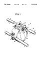
- FIG. 1 shows a movable lens arranged on guide rods according to the present invention.
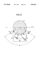
- FIG. 2 shows a cross-sectional view of the guide rod and the permanent magnetic assembly along lines 2--2 in FIG. 1.
- FIG. 1 shows a movable lens assembly 2 arranged on guide rods 4 and 6.
- the guide rods 4 and 6 are two hardened steel rods.
- the movable lens assembly 2 includes a lens cell 10 having a perimeter 10a with a permanent magnet assembly 12 arranged thereon at the top of the lens cell 10 as shown.
- a pre-load bearing 14 and guide beating 16 are also arranged on the perimeter 10a of the lens cell 10 at a 90° angle with respect to the permanent magnetic assembly 12. The pre-load beating 14 and guide beating 16 cooperate with the guide rod 6 to further support and position the lens cell 10 along the guide rod 4.
- the permanent magnet assembly 12 has a permanent magnet 20 which provides a closed-coupled attractive magnetic force to support the lens assembly 2 to the guide rod 4.
- Magnetic force lines f1 and f2 illustrate the magnetic force applied to the guide rod 4 as a close-coupled attractive magnetic force.
- the permanent magnet 20, in the embodiment, is U-shaped, having a north pole 40 and a south pole 42, and having a V-shaped recessed longitudinal channel 44 placed in close proximity to the guide rod 4 on the permanent magnet assembly 12 to attract the guide rod and hold it against the ball bearings.
- the north pole 40 and south pole 42 are disposed parallel to and spaced apart from each other and also parallel to a lengthwise axis (not shown) of guide rod 4. As shown in FIG. 2, the north pole 40 and south pole 42 are disposed about the guide rod 4 with a small air gap or clearance 41, at an arc segment of ⁇ . In a preferred embodiment, ⁇ equals 60°.
- the permanent magnet assembly 12 in the preferred embodiment has four ball bearings 22, 24, 26 and 28 arranged in a V-shaped configuration on each side of the permanent magnet assembly 12, as shown.
- the four ball bearings 22, 24, 26 and 28 provide guidance for the lens cell 10 by rolling against the underside of the guide rod 4.
- the four ball bearings 22, 24, 26 and 28 provide all supportive and guiding functions.
- the rotational guide beatings 24 and 26 are disposed about the guide rod, and contact it at an arc segment of ⁇ 1 and ⁇ 3 respectively with respect to the horizontal plane H of the guide rod 4, as shown.
- ⁇ 1 and ⁇ 3 30°
- ⁇ 2 equals 120°.
- the lens cell 10 is secured against shock loads that may exceed the close-coupled magnetic attraction forces f1 and f2 by means of a clearance aperture 30 passing through the permanent magnet assembly 12.
- the aperture 30 helps to prevent lens cell 10 from breaking if the permanent magnet 20 releases the guide rod 4 in the event shock loading exceeds the close-coupled magnetic force.
- the guide rod 4 is thus surrounded by the rest of the assembly 12 to retain the guide rod 4 and to prevent the lens from falling off the guide rod 4.
- additional guidance must be provided by the pair of bearings 14 and 16 which cooperate with a second guide rod 6 in order to control rotation of the assembly out of the optical axes.
- the guide bearing 16 is mounted on a rigid shaft (not shown), and the pre-load bearing 14 is mounted on two spring rods (not shown) to provide pre-loading.
Abstract
Description
Claims (9)
Priority Applications (7)
| Application Number | Priority Date | Filing Date | Title |
|---|---|---|---|
| US08/045,958 US5515210A (en) | 1993-04-12 | 1993-04-12 | Permanent magnetic suspension with roller guides |
| CA002120981A CA2120981C (en) | 1993-04-12 | 1994-04-11 | Permanent magnetic suspension with roller guides |
| IL109285A IL109285A (en) | 1993-04-12 | 1994-04-11 | Lens assembly with permanent magnetic suspension with roller guides |
| DE69408357T DE69408357T2 (en) | 1993-04-12 | 1994-04-11 | Permanent magnet suspension with roller guide |
| EP94105584A EP0620463B1 (en) | 1993-04-12 | 1994-04-11 | Permanent magnetic suspension with roller guides |
| JP6073653A JP2980807B2 (en) | 1993-04-12 | 1994-04-12 | Permanent magnet suspension with roller guide |
| KR1019940007578A KR0175956B1 (en) | 1993-04-12 | 1994-04-12 | Permanent magnetic suspension with roller guides |
Applications Claiming Priority (1)
| Application Number | Priority Date | Filing Date | Title |
|---|---|---|---|
| US08/045,958 US5515210A (en) | 1993-04-12 | 1993-04-12 | Permanent magnetic suspension with roller guides |
Publications (1)
| Publication Number | Publication Date |
|---|---|
| US5515210A true US5515210A (en) | 1996-05-07 |
Family
ID=21940759
Family Applications (1)
| Application Number | Title | Priority Date | Filing Date |
|---|---|---|---|
| US08/045,958 Expired - Lifetime US5515210A (en) | 1993-04-12 | 1993-04-12 | Permanent magnetic suspension with roller guides |
Country Status (7)
| Country | Link |
|---|---|
| US (1) | US5515210A (en) |
| EP (1) | EP0620463B1 (en) |
| JP (1) | JP2980807B2 (en) |
| KR (1) | KR0175956B1 (en) |
| CA (1) | CA2120981C (en) |
| DE (1) | DE69408357T2 (en) |
| IL (1) | IL109285A (en) |
Cited By (13)
| Publication number | Priority date | Publication date | Assignee | Title |
|---|---|---|---|---|
| US5675442A (en) * | 1994-01-14 | 1997-10-07 | Leica Inc. | Microscope lens guide system |
| US6323996B1 (en) * | 1998-06-03 | 2001-11-27 | George M. Watters | Reflector telescope with an adjustable secondary mirror assembly |
| US20060077576A1 (en) * | 2004-10-07 | 2006-04-13 | Melles Griot, Inc. | Sliding track for optical apparatus |
| US20070195438A1 (en) * | 2006-02-20 | 2007-08-23 | Samsung Electro-Mechanics Co., Ltd. | Lens driving device |
| US20100091383A1 (en) * | 2008-10-09 | 2010-04-15 | Asia Optical Co., Inc. | Zoom lens assembly and zoom lens module |
| US20110122519A1 (en) * | 2008-08-08 | 2011-05-26 | Nikon Corporation | Lens barrel and image capturing apparatus |
| US20110199675A1 (en) * | 2010-02-11 | 2011-08-18 | Leica Microsystems (Schweiz) Ag | System for Guiding Optical Elements |
| DE102011078302A1 (en) * | 2011-06-29 | 2013-01-03 | Carl Zeiss Microimaging Gmbh | lens |
| WO2016003505A1 (en) | 2014-07-02 | 2016-01-07 | Geoffrey Brooks Consultants, Llc | Peptide-based compositions and methods of use |
| US20210018719A1 (en) * | 2018-04-12 | 2021-01-21 | Lg Innotek Co., Ltd. | Lens assembly |
| USRE49185E1 (en) | 2013-03-06 | 2022-08-23 | Vermont Slate & Copper Services, Inc. | Snow fence for solar panel |
| US11644684B2 (en) | 2020-02-28 | 2023-05-09 | Canon Kabushiki Kaisha | Lens apparatus and image pickup apparatus |
| US11681119B2 (en) * | 2020-02-19 | 2023-06-20 | Canon Kabushiki Kaisha | Optical driving apparatus and optical apparatus |
Families Citing this family (9)
| Publication number | Priority date | Publication date | Assignee | Title |
|---|---|---|---|---|
| EP0823064B1 (en) * | 1995-04-28 | 2004-06-02 | Leica Microsystems Inc. | Microscope lens guide system |
| GB9609367D0 (en) * | 1996-05-03 | 1996-07-10 | Pilkington Perkin Elmer Ltd | Lens mounting |
| DE10339255B4 (en) * | 2003-08-26 | 2005-08-18 | Leica Microsystems (Schweiz) Ag | Guide system for zoom systems |
| EP1836518B1 (en) | 2005-01-12 | 2013-10-30 | Trimble Jena GmbH | Translational positioning device |
| KR20080023331A (en) * | 2005-07-07 | 2008-03-13 | 코닌클리케 필립스 일렉트로닉스 엔.브이. | Actuator assembly, method of driving an actuator assembly and apparatus for driving an actuator assembly |
| DE102006038455A1 (en) * | 2006-08-16 | 2008-02-21 | Carl Zeiss Smt Ag | Optical system for semiconductor lithography, has adjusting unit positioning optical component, where contact points of adjusting unit at optical component is selected, such that no moments develop at optical component |
| EP2811328B1 (en) * | 2013-06-04 | 2024-04-10 | Leica Geosystems AG | Positioning device, especially for the adjustment of lenses or lens systems in optical devices |
| JP7204526B2 (en) * | 2019-02-26 | 2023-01-16 | キヤノン株式会社 | lens driver |
| WO2022201702A1 (en) * | 2021-03-22 | 2022-09-29 | 株式会社ニコン | Lens barrel and imaging device |
Citations (7)
| Publication number | Priority date | Publication date | Assignee | Title |
|---|---|---|---|---|
| JPS58122506A (en) * | 1981-12-10 | 1983-07-21 | Mamiya Koki Kk | Lens driving device |
| US4676605A (en) * | 1981-07-14 | 1987-06-30 | Canon Kabushiki Kaisha | Construction of lens barrel operated by electromagnetic induction |
| US4740064A (en) * | 1985-04-23 | 1988-04-26 | Victor Company Of Japan, Ltd. | Zoom lens apparatus |
| US5182481A (en) * | 1990-05-28 | 1993-01-26 | Sony Corporation | Voice coil type actuator |
| US5272567A (en) * | 1990-10-23 | 1993-12-21 | Sony Corporation | Lens barrel having reference shafts movably supporting lenses |
| US5289318A (en) * | 1990-07-31 | 1994-02-22 | Canon Kabushiki Kaisha | Optical apparatus provided with a driving unit for moving a lens |
| US5301066A (en) * | 1991-06-28 | 1994-04-05 | Olympus Optical Co., Ltd. | Lens barrel |
Family Cites Families (4)
| Publication number | Priority date | Publication date | Assignee | Title |
|---|---|---|---|---|
| JPS58156967A (en) * | 1982-03-15 | 1983-09-19 | Fuji Xerox Co Ltd | Optical device for copying machine |
| EP0316684B1 (en) * | 1987-11-17 | 1994-02-23 | Lasag Ag | Support for optical element |
| SU1744681A1 (en) * | 1989-12-05 | 1992-06-30 | Войсковая часть 33491 | Clamping device for optical members |
| US5210648A (en) * | 1991-09-24 | 1993-05-11 | Eastman Kodak Company | Adjustable mount for cylindrical lens with independent rotational feature |
-
1993
- 1993-04-12 US US08/045,958 patent/US5515210A/en not_active Expired - Lifetime
-
1994
- 1994-04-11 DE DE69408357T patent/DE69408357T2/en not_active Expired - Fee Related
- 1994-04-11 CA CA002120981A patent/CA2120981C/en not_active Expired - Fee Related
- 1994-04-11 EP EP94105584A patent/EP0620463B1/en not_active Expired - Lifetime
- 1994-04-11 IL IL109285A patent/IL109285A/en not_active IP Right Cessation
- 1994-04-12 KR KR1019940007578A patent/KR0175956B1/en not_active IP Right Cessation
- 1994-04-12 JP JP6073653A patent/JP2980807B2/en not_active Expired - Fee Related
Patent Citations (7)
| Publication number | Priority date | Publication date | Assignee | Title |
|---|---|---|---|---|
| US4676605A (en) * | 1981-07-14 | 1987-06-30 | Canon Kabushiki Kaisha | Construction of lens barrel operated by electromagnetic induction |
| JPS58122506A (en) * | 1981-12-10 | 1983-07-21 | Mamiya Koki Kk | Lens driving device |
| US4740064A (en) * | 1985-04-23 | 1988-04-26 | Victor Company Of Japan, Ltd. | Zoom lens apparatus |
| US5182481A (en) * | 1990-05-28 | 1993-01-26 | Sony Corporation | Voice coil type actuator |
| US5289318A (en) * | 1990-07-31 | 1994-02-22 | Canon Kabushiki Kaisha | Optical apparatus provided with a driving unit for moving a lens |
| US5272567A (en) * | 1990-10-23 | 1993-12-21 | Sony Corporation | Lens barrel having reference shafts movably supporting lenses |
| US5301066A (en) * | 1991-06-28 | 1994-04-05 | Olympus Optical Co., Ltd. | Lens barrel |
Cited By (21)
| Publication number | Priority date | Publication date | Assignee | Title |
|---|---|---|---|---|
| US5675442A (en) * | 1994-01-14 | 1997-10-07 | Leica Inc. | Microscope lens guide system |
| US6323996B1 (en) * | 1998-06-03 | 2001-11-27 | George M. Watters | Reflector telescope with an adjustable secondary mirror assembly |
| US20060077576A1 (en) * | 2004-10-07 | 2006-04-13 | Melles Griot, Inc. | Sliding track for optical apparatus |
| US7230778B2 (en) | 2004-10-07 | 2007-06-12 | Melles, Griot, Inc | Sliding track for optical apparatus |
| US20070195438A1 (en) * | 2006-02-20 | 2007-08-23 | Samsung Electro-Mechanics Co., Ltd. | Lens driving device |
| US7457060B2 (en) * | 2006-02-20 | 2008-11-25 | Samsung Electro-Mechanics Co., Ltd. | Lens driving device |
| US20110122519A1 (en) * | 2008-08-08 | 2011-05-26 | Nikon Corporation | Lens barrel and image capturing apparatus |
| US8508871B2 (en) * | 2008-08-08 | 2013-08-13 | Nikon Corporation | Lens barrel and image capturing apparatus |
| US20100091383A1 (en) * | 2008-10-09 | 2010-04-15 | Asia Optical Co., Inc. | Zoom lens assembly and zoom lens module |
| US7782545B2 (en) * | 2008-10-09 | 2010-08-24 | Asia Optical Co., Inc. | Zoom lens assembly and zoom lens module |
| CN102213813A (en) * | 2010-02-11 | 2011-10-12 | 徕卡显微系统(瑞士)股份公司 | System for guiding optical elements |
| US20110199675A1 (en) * | 2010-02-11 | 2011-08-18 | Leica Microsystems (Schweiz) Ag | System for Guiding Optical Elements |
| US8625212B2 (en) * | 2010-02-11 | 2014-01-07 | Leica Microsystems (Schweiz) Ag | System for guiding optical elements |
| CN102213813B (en) * | 2010-02-11 | 2015-09-30 | 徕卡显微系统(瑞士)股份公司 | The guidance system of optical element |
| DE102011078302A1 (en) * | 2011-06-29 | 2013-01-03 | Carl Zeiss Microimaging Gmbh | lens |
| US8611029B2 (en) | 2011-06-29 | 2013-12-17 | Carl Zeiss Microscopy Gmbh | Objective lens assembly |
| USRE49185E1 (en) | 2013-03-06 | 2022-08-23 | Vermont Slate & Copper Services, Inc. | Snow fence for solar panel |
| WO2016003505A1 (en) | 2014-07-02 | 2016-01-07 | Geoffrey Brooks Consultants, Llc | Peptide-based compositions and methods of use |
| US20210018719A1 (en) * | 2018-04-12 | 2021-01-21 | Lg Innotek Co., Ltd. | Lens assembly |
| US11681119B2 (en) * | 2020-02-19 | 2023-06-20 | Canon Kabushiki Kaisha | Optical driving apparatus and optical apparatus |
| US11644684B2 (en) | 2020-02-28 | 2023-05-09 | Canon Kabushiki Kaisha | Lens apparatus and image pickup apparatus |
Also Published As
| Publication number | Publication date |
|---|---|
| CA2120981A1 (en) | 1994-10-13 |
| IL109285A (en) | 1998-02-22 |
| CA2120981C (en) | 1999-09-28 |
| JP2980807B2 (en) | 1999-11-22 |
| JPH0749443A (en) | 1995-02-21 |
| EP0620463B1 (en) | 1998-02-04 |
| DE69408357T2 (en) | 1998-08-27 |
| EP0620463A1 (en) | 1994-10-19 |
| DE69408357D1 (en) | 1998-03-12 |
| KR0175956B1 (en) | 1999-05-15 |
Similar Documents
| Publication | Publication Date | Title |
|---|---|---|
| US5515210A (en) | Permanent magnetic suspension with roller guides | |
| US7113351B2 (en) | Systems and methods for actuating lens assemblies | |
| US8320756B2 (en) | Single actuator configuration for a camera module | |
| CN204203597U (en) | Imaging device | |
| US4635887A (en) | Adjustable mountings | |
| KR101625818B1 (en) | Apparatus for moving lens in camera module for portable device | |
| CN204203598U (en) | Imaging device | |
| US11165325B2 (en) | Drive apparatus having drive unit using magnetic circuit | |
| US4283743A (en) | Yoke mounting assembly for a video camera | |
| US20180039158A1 (en) | Blade driving device | |
| JPH08140U (en) | Slide displacement device | |
| US20110199675A1 (en) | System for Guiding Optical Elements | |
| JP2803896B2 (en) | Optical equipment | |
| US20120237147A1 (en) | Integrated ball cage | |
| JP2015087699A (en) | Driving unit and optical instrument | |
| JP7252726B2 (en) | Driving device, lens driving device and electronic device | |
| US3730007A (en) | Rolamite | |
| CA2071085A1 (en) | Rolling element cage constraint | |
| US7050226B2 (en) | Play-free rotary mounting | |
| US20110215889A1 (en) | Stabilized ball bearings for camera lens | |
| CN218003823U (en) | Optical actuator, camera module and electronic equipment | |
| WO2008041171A2 (en) | Actuator assembly and opto-mechanical device comprising an actuator assembly | |
| JPS6397911A (en) | Actuator for telescope | |
| JP4253177B2 (en) | Image shake prevention device | |
| KR102597174B1 (en) | sensor shifting module and camera module having the same |
Legal Events
| Date | Code | Title | Description |
|---|---|---|---|
| AS | Assignment |
Owner name: HUGHES AIRCRAFT COMPANY, CALIFORNIA Free format text: ASSIGNMENT OF ASSIGNORS INTEREST.;ASSIGNOR:DEVENYI, GABOR;REEL/FRAME:006517/0572 Effective date: 19930309 |
|
| STPP | Information on status: patent application and granting procedure in general |
Free format text: APPLICATION UNDERGOING PREEXAM PROCESSING |
|
| CC | Certificate of correction | ||
| AS | Assignment |
Owner name: RAYTHEON COMPANY, MASSACHUSETTS Free format text: MERGER;ASSIGNOR:HE HOLDINGS, INC.;REEL/FRAME:009790/0503 Effective date: 19971217 |
|
| AS | Assignment |
Owner name: HE HOLDINGS, INC., CALIFORNIA Free format text: CHANGE OF NAME;ASSIGNOR:HUGHES AIRCRAFT COMPANY;REEL/FRAME:009798/0610 Effective date: 19951208 |
|
| FPAY | Fee payment |
Year of fee payment: 4 |
|
| FPAY | Fee payment |
Year of fee payment: 8 |
|
| FPAY | Fee payment |
Year of fee payment: 12 |
|
| AS | Assignment |
Owner name: RAYTHEON CANADA LIMITED, CANADA Free format text: ASSIGNMENT OF ASSIGNORS INTEREST;ASSIGNOR:RAYTHEON COMPANY;REEL/FRAME:027558/0411 Effective date: 20120105 |