US5524357A - Instrument cleaner with converging steam jets - Google Patents
Instrument cleaner with converging steam jets Download PDFInfo
- Publication number
- US5524357A US5524357A US08/362,833 US36283394A US5524357A US 5524357 A US5524357 A US 5524357A US 36283394 A US36283394 A US 36283394A US 5524357 A US5524357 A US 5524357A
- Authority
- US
- United States
- Prior art keywords
- fluid
- manifold
- instrument
- single point
- oriented
- Prior art date
- Legal status (The legal status is an assumption and is not a legal conclusion. Google has not performed a legal analysis and makes no representation as to the accuracy of the status listed.)
- Expired - Fee Related
Links
Images


Classifications
-
- B—PERFORMING OPERATIONS; TRANSPORTING
- B08—CLEANING
- B08B—CLEANING IN GENERAL; PREVENTION OF FOULING IN GENERAL
- B08B3/00—Cleaning by methods involving the use or presence of liquid or steam
- B08B3/02—Cleaning by the force of jets or sprays
-
- A—HUMAN NECESSITIES
- A61—MEDICAL OR VETERINARY SCIENCE; HYGIENE
- A61B—DIAGNOSIS; SURGERY; IDENTIFICATION
- A61B90/00—Instruments, implements or accessories specially adapted for surgery or diagnosis and not covered by any of the groups A61B1/00 - A61B50/00, e.g. for luxation treatment or for protecting wound edges
- A61B90/70—Cleaning devices specially adapted for surgical instruments
-
- A—HUMAN NECESSITIES
- A61—MEDICAL OR VETERINARY SCIENCE; HYGIENE
- A61L—METHODS OR APPARATUS FOR STERILISING MATERIALS OR OBJECTS IN GENERAL; DISINFECTION, STERILISATION OR DEODORISATION OF AIR; CHEMICAL ASPECTS OF BANDAGES, DRESSINGS, ABSORBENT PADS OR SURGICAL ARTICLES; MATERIALS FOR BANDAGES, DRESSINGS, ABSORBENT PADS OR SURGICAL ARTICLES
- A61L2/00—Methods or apparatus for disinfecting or sterilising materials or objects other than foodstuffs or contact lenses; Accessories therefor
- A61L2/02—Methods or apparatus for disinfecting or sterilising materials or objects other than foodstuffs or contact lenses; Accessories therefor using physical phenomena
- A61L2/04—Heat
- A61L2/06—Hot gas
- A61L2/07—Steam
-
- A—HUMAN NECESSITIES
- A61—MEDICAL OR VETERINARY SCIENCE; HYGIENE
- A61L—METHODS OR APPARATUS FOR STERILISING MATERIALS OR OBJECTS IN GENERAL; DISINFECTION, STERILISATION OR DEODORISATION OF AIR; CHEMICAL ASPECTS OF BANDAGES, DRESSINGS, ABSORBENT PADS OR SURGICAL ARTICLES; MATERIALS FOR BANDAGES, DRESSINGS, ABSORBENT PADS OR SURGICAL ARTICLES
- A61L2/00—Methods or apparatus for disinfecting or sterilising materials or objects other than foodstuffs or contact lenses; Accessories therefor
- A61L2/24—Apparatus using programmed or automatic operation
-
- B—PERFORMING OPERATIONS; TRANSPORTING
- B08—CLEANING
- B08B—CLEANING IN GENERAL; PREVENTION OF FOULING IN GENERAL
- B08B2230/00—Other cleaning aspects applicable to all B08B range
- B08B2230/01—Cleaning with steam
Definitions
- This invention relates generally to surgical instrument cleaning devices, specifically to a steam jet cleaner for removing surgical debris from instruments.
- Autoclaves are shown in U.S. Pat. Nos. 3,450,487 to Wallden (1969); 4,663,122 to Sparks (1987); and 5,271,893 to Newman (1993). These devices sterilize instruments by immersing them in a low velocity flow of high temperature steam within a sealed chamber.
- the Newman and Sparks devices each includes a single steam inlet (reference numerals 18 and 36, respectively) for its chamber.
- the Wallden device provides multiple openings and diffuser jets (reference numerals 19 and 20, respectively) that emit parallel jets of steam directed at the top of the chamber for filling it; the parallel jets are not directed at the instruments, which would be positioned on the bottom of the chamber.
- the autoclaving process sterilizes the surgical debris on the instruments, it does not remove them. Moreover, the high temperature in autoclaving even bakes or hardens the debris on the instruments. As a result, repeated use and autoclaving of surgical instruments cause a buildup of debris that gradually reduces their cutting performance.
- U.S. Pat. No. 4,414,037 to Friedheim (1983) shows a device with a single-jet nozzle (reference numeral 14) for sterilizing instruments and blowing away surgical debris.
- the single nozzle produces a diverging steam jet that is only effective when an instrument is held very close--so close that inadvertent contact and damage to the instrument can easily happen. Its single jet can only clean one side of an instrument at a time.
- the externally mounted nozzle is pointed in the direction of the user, who can easily be burned by the steam.
- surgical debris dislodged from the instrument and thrown up in the air by the jet poses a definite health hazard to the user and those nearby.
- the steam jet would be pointed at a countertop or floor, which would quickly become contaminated with condensed steam.
- cannulas are also reused.
- cleaning a cannula is problematic, because the interior of its extremely small channel is virtually impossible to reach with conventional methods and cleaning devices.
- the primary objects and advantages of the present invention are to provide an improved surgical instrument cleaner, a surgical instrument cleaner which effectively removes surgical debris from instruments to prevent buildup and maintain maximum cutting performance, which cleans instruments very quickly, which cleans the interior of cannulas, which removes surgical debris from delicate instruments without damaging them, which is safe to the user, which keeps the work area clean, and which is easy to use.
- a surgical instrument cleaner includes a housing with a vented steam containment chamber, a steam source, a circular steam manifold positioned in the chamber, a single-jet nozzle also positioned in the chamber, and a valve for directing steam to either the circular manifold or the single-jet nozzle.
- the circular manifold includes multiple nozzles emitting converging steam jets to blast away surgical debris simultaneously from all sides of an instrument.
- the single-jet nozzle includes a luer lock that receives a standard cannula for cleaning the interior thereof. The jets from both the circular manifold and the single-jet nozzle are directed away from the user and into the chamber, which collects the steam and surgical debris for improved worker safety.
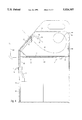
- FIG. 1 is a front perspective view of a surgical instrument cleaner in accordance with a preferred embodiment of the invention.
- FIG. 2A is a side view of a circular manifold of the surgical instrument cleaner emitting converging steam jets.
- FIG. 2B is a bottom view of the circular manifold.
- FIG. 3 is a partial sectional side view of a single-jet nozzle of the surgical instrument cleaner.
- FIG. 4 is a side sectional view of the surgical instrument cleaner taken along line 4--4 in FIG. 1.
- a surgical instrument cleaner includes an aluminum housing 10 containing a steam source 11, which can be any suitable steam source well known in the art.
- Housing 10 has an open top that receives a removable, stainless steel collection tray 12, which is covered by a removable, transparent cover 13 made of heat resistant Lexan (a registered trademark of General Electric).
- Collection tray 12 and cover 13 cooperate to define a containment chamber 14.
- the rear edge of collection tray 12 has a clipped portion that forms an exhaust vent 15 in conjunction with the rear edge of cover 13.
- Steam source 11 is connected to a front-mounted control valve 16 with tubing 17.
- Valve 16 is manually selectable to direct steam into either a circular manifold 18 or a single-jet nozzle 19 through connecting tubing 20 and 21, respectively.
- Circular manifold 18 and single-jet nozzle 19 are positioned in intake openings 22 and 23, respectively, on the angled front face of cover 13.
- a hand brace 24 extends from the front of housing 10.
- Other necessary controls and instruments for controlling the operation of steam source 11 are well known in the art, so they are not shown.
- Circular manifold 18 is shown in side and bottom views in FIGS. 2A and 2B, respectively.
- Circular manifold 18 has two sealed free ends, and four nozzles 25 (not shown in FIG. 2A) arranged thereon at 90 degree intervals.
- Nozzles 25 are positioned for directing converging steam jets 26 generally rearwardly at a single point in space. Steam jets 26 can quickly blast away biological debris simultaneously from all sides of a surgical instrument 33.
- Circular manifold 18 is wide enough to allow an instrument to be maneuvered therein without danger of inadvertent contact.
- No prior art device includes nozzles oriented for emitting converging jets of steam.
- Nozzle 19 is shown in a partial side sectional view in FIG. 3.
- Nozzle 19 provides a single, narrow steam jet 27 for cleaning the deep recesses or cavities of instruments (not shown).
- each of the two horizontal portions (one shown) of hand brace 24 is slidably fitted between a top sheet member 30 and a pair of screws 31 that extend into each side of housing 10.
- control valve 16 is operated to direct steam to either circular manifold 18 or single-jet nozzle 19.
- a surgical instrument (not shown) is positioned in steam jets 26 or 27 through openings 22 or 23 (FIG. 1), respectively, for blasting away debris to prevent buildup and maintain maximum cutting performance.
- Hand brace 24 is usable for supporting and steadying a user's hand, and it can be slid in or out of housing 10 to achieve the most comfortable position.
- a cannula (FIG. 3) can be cleaned by first removing cover 13, connecting it to luer lock 28, and replacing cover 13. After an instrument is cleaned of surgical debris, it can be sterilized in the conventional manner with other devices.
- Airflow 32 positively prevents airborne debris blasted from an instrument and contaminated steam from reaching; the user. Furthermore, airborne debris and much of the moisture in the steam are collected in tray 12, so that the work area is kept clean. Tray 12 and cover 13 can both be easily removed from housing 10 for cleaning.
- the shape of the circular manifold can be changed, as long as the nozzles are generally directed at a single point.
- a different number of nozzles can be arranged on the manifold.
- An external steam source can be used.
- the various components of the steam cleaner can be made of materials other than those described.
- other types of tubular devices can be attached to the luer lock for cleaning.
- the steam cleaner can be used for cleaning a variety of other devices in addition to surgical instruments.
- the cleaner can be adapted for producing jets of liquid. Therefore, the scope of the invention should not be determined by the examples given, but by the appended claims and their legal equivalents.
Abstract
A surgical instrument cleaner includes a containment chamber with an intake opening on a front thereof and an exhaust vent on a rear thereof. A manifold is positioned in the intake opening, and connected to a steam source. Nozzles arranged around the manifold emit converging steam jets at a single point positioned away from a plane defined by the nozzles. The steam jets are directed rearwardly into the containment chamber, so that they create a front-to-rear airflow between the intake and the exhaust vent. An instrument is positionable at the jet convergence point for cleaning. The airflow carries steam and airborne debris blasted from the instrument safely away from the user.
Description
1. Field of the Invention
This invention relates generally to surgical instrument cleaning devices, specifically to a steam jet cleaner for removing surgical debris from instruments.
2. Prior Art
In microsurgery, and especially ophthalmic surgery, extremely accurate and smooth incisions are required. To fill this need, diamond scalpels with superior sharpness and hardness have been developed. Diamond scalpels are extremely expensive, so they are often reused hundreds of times. Stainless steel scalpels are also reused. During surgery, the scalpels are coated with a variety of surgical debris, such as intraocular fluids, proteins, viscoelastic materials, etc. After each use, the scalpels are sterilized in a steam chamber or autoclave.
Autoclaves are shown in U.S. Pat. Nos. 3,450,487 to Wallden (1969); 4,663,122 to Sparks (1987); and 5,271,893 to Newman (1993). These devices sterilize instruments by immersing them in a low velocity flow of high temperature steam within a sealed chamber. The Newman and Sparks devices each includes a single steam inlet (reference numerals 18 and 36, respectively) for its chamber. The Wallden device provides multiple openings and diffuser jets ( reference numerals 19 and 20, respectively) that emit parallel jets of steam directed at the top of the chamber for filling it; the parallel jets are not directed at the instruments, which would be positioned on the bottom of the chamber.
Although the autoclaving process sterilizes the surgical debris on the instruments, it does not remove them. Moreover, the high temperature in autoclaving even bakes or hardens the debris on the instruments. As a result, repeated use and autoclaving of surgical instruments cause a buildup of debris that gradually reduces their cutting performance.
U.S. Pat. No. 4,414,037 to Friedheim (1983) shows a device with a single-jet nozzle (reference numeral 14) for sterilizing instruments and blowing away surgical debris. However, the single nozzle produces a diverging steam jet that is only effective when an instrument is held very close--so close that inadvertent contact and damage to the instrument can easily happen. Its single jet can only clean one side of an instrument at a time. In addition, the externally mounted nozzle is pointed in the direction of the user, who can easily be burned by the steam. Furthermore, surgical debris dislodged from the instrument and thrown up in the air by the jet poses a definite health hazard to the user and those nearby. In a typical work area, the steam jet would be pointed at a countertop or floor, which would quickly become contaminated with condensed steam.
In addition to cutting instruments, cannulas are also reused. However, cleaning a cannula is problematic, because the interior of its extremely small channel is virtually impossible to reach with conventional methods and cleaning devices.
Accordingly the primary objects and advantages of the present invention are to provide an improved surgical instrument cleaner, a surgical instrument cleaner which effectively removes surgical debris from instruments to prevent buildup and maintain maximum cutting performance, which cleans instruments very quickly, which cleans the interior of cannulas, which removes surgical debris from delicate instruments without damaging them, which is safe to the user, which keeps the work area clean, and which is easy to use. Other objects and advantages of the invention will become apparent from a study of the drawing figures and the following description.
A surgical instrument cleaner includes a housing with a vented steam containment chamber, a steam source, a circular steam manifold positioned in the chamber, a single-jet nozzle also positioned in the chamber, and a valve for directing steam to either the circular manifold or the single-jet nozzle. The circular manifold includes multiple nozzles emitting converging steam jets to blast away surgical debris simultaneously from all sides of an instrument. The single-jet nozzle includes a luer lock that receives a standard cannula for cleaning the interior thereof. The jets from both the circular manifold and the single-jet nozzle are directed away from the user and into the chamber, which collects the steam and surgical debris for improved worker safety.
FIG. 1 is a front perspective view of a surgical instrument cleaner in accordance with a preferred embodiment of the invention.
FIG. 2A is a side view of a circular manifold of the surgical instrument cleaner emitting converging steam jets.
FIG. 2B is a bottom view of the circular manifold.
FIG. 3 is a partial sectional side view of a single-jet nozzle of the surgical instrument cleaner.
FIG. 4 is a side sectional view of the surgical instrument cleaner taken along line 4--4 in FIG. 1.
______________________________________ 10.Housing 11.Conventional Steam Source 12. Removable Collection Tray 13.Transparent Cover 14.Containment Chamber 15. Exhaust Vent 16. Control Valve 17. Tubing 18. Circular Manifold 19. Single-Jet Nozzle 20. Tubing 21. Tubing 22.Intake Opening 23.Intake Opening 24. Hand Brace 25.Nozzles 26. Steam Jets 27. Steam Jet 28.Luer Lock 29.Cannula Assembly 30.Top Sheet Member 31. Screws 32.Airflow 33. Surgical Instrument ______________________________________
In accordance with a preferred embodiment of the invention shown in the front perspective view in FIG. 1, a surgical instrument cleaner includes an aluminum housing 10 containing a steam source 11, which can be any suitable steam source well known in the art. Housing 10 has an open top that receives a removable, stainless steel collection tray 12, which is covered by a removable, transparent cover 13 made of heat resistant Lexan (a registered trademark of General Electric). Collection tray 12 and cover 13 cooperate to define a containment chamber 14. The rear edge of collection tray 12 has a clipped portion that forms an exhaust vent 15 in conjunction with the rear edge of cover 13.
Steam source 11 is connected to a front-mounted control valve 16 with tubing 17. Valve 16 is manually selectable to direct steam into either a circular manifold 18 or a single-jet nozzle 19 through connecting tubing 20 and 21, respectively. Circular manifold 18 and single-jet nozzle 19 are positioned in intake openings 22 and 23, respectively, on the angled front face of cover 13. A hand brace 24 extends from the front of housing 10. Other necessary controls and instruments for controlling the operation of steam source 11 are well known in the art, so they are not shown.
As shown in the side sectional view of the surgical instrument cleaner in FIG. 4, each of the two horizontal portions (one shown) of hand brace 24 is slidably fitted between a top sheet member 30 and a pair of screws 31 that extend into each side of housing 10.
In use, control valve 16 is operated to direct steam to either circular manifold 18 or single-jet nozzle 19. A surgical instrument (not shown) is positioned in steam jets 26 or 27 through openings 22 or 23 (FIG. 1), respectively, for blasting away debris to prevent buildup and maintain maximum cutting performance. Hand brace 24 is usable for supporting and steadying a user's hand, and it can be slid in or out of housing 10 to achieve the most comfortable position. A cannula (FIG. 3) can be cleaned by first removing cover 13, connecting it to luer lock 28, and replacing cover 13. After an instrument is cleaned of surgical debris, it can be sterilized in the conventional manner with other devices.
Because steam jets 26 or 27 are pointed rearwardly and downwardly, they create a front-to-rear airflow 32 that enters through intake openings 22 or 23 (FIG. 1), respectively, and exits through vent 15. Airflow 32 positively prevents airborne debris blasted from an instrument and contaminated steam from reaching; the user. Furthermore, airborne debris and much of the moisture in the steam are collected in tray 12, so that the work area is kept clean. Tray 12 and cover 13 can both be easily removed from housing 10 for cleaning.
Accordingly the reader will see that I have provided an improved surgical instrument cleaner. It thoroughly blasts away surgical debris from instruments, including the interior of cannulas. It quickly cleans an instrument simultaneously from all sides thereof. It cleans delicate surgical instruments without damaging them. It prevents debris buildup on surgical instruments to maintain top cutting performance. It safely directs steam and airborne surgical debris away from the user. It keeps the work area clean, and it is very easy to use.
Although the above descriptions are specific, they should not be considered as limitations on the scope of the invention, but only as examples of the preferred embodiment. Many other ramifications and variations are possible within the teachings of the invention. For example, the shape of the circular manifold can be changed, as long as the nozzles are generally directed at a single point. A different number of nozzles can be arranged on the manifold. An external steam source can be used. The various components of the steam cleaner can be made of materials other than those described. In addition to cannulas, other types of tubular devices can be attached to the luer lock for cleaning. The steam cleaner can be used for cleaning a variety of other devices in addition to surgical instruments. The cleaner can be adapted for producing jets of liquid. Therefore, the scope of the invention should not be determined by the examples given, but by the appended claims and their legal equivalents.
Claims (7)
1. An instrument cleaning device, comprising:
a manifold adapted to be connected to a fluid source for receiving a pressurized fluid therefrom; and
a plurality of nozzles arranged on said manifold and oriented to emit a plurality of converging fluid jets generally meeting at a single point positioned away from a plane generally defined by said nozzles;
whereby an instrument is positionable at said single point for simultaneously cleaning all sides thereof.
2. An instrument cleaning device, comprising:
a manifold adapted to be connected to a steam source for receiving pressurized steam therefrom; and
a plurality of nozzles arranged on said manifold and oriented to emit a plurality of converging steam jets generally meeting at a single point;
whereby an instrument is positionable at said single point for simultaneously cleaning all sides thereof.
3. An instrument cleaning device, comprising:
a containment chamber having an intake opening on a front thereof and an exhaust vent on a rear thereof;
a manifold positioned adjacent said intake opening and adapted to be connected to a fluid source for receiving a pressurized fluid therefrom; and
a plurality of nozzles arranged on said manifold and oriented to emit a plurality of converging fluid jets generally meeting at a single point, said nozzles being oriented to direct said fluid jets generally rearwardly into said containment chamber;
whereby an instrument is positionable at said single point for simultaneously cleaning all sides thereof, said fluid jets creating a front-to-rear airflow from said intake opening to said exhaust vent to safely direct said fluid away from a user.
4. An instrument cleaning device, comprising:
a containment chamber defined by a fluid collection tray on a bottom thereof and a transparent cover on a top thereof, said containment chamber having an intake opening on a front thereof and an exhaust vent on a rear thereof:
a manifold positioned adjacent said intake opening and adapted to be connected to a fluid source for receiving a pressurized fluid therefrom; and
a plurality of nozzles arranged on said manifold and oriented to emit a plurality of converging fluid jets generally meeting at a single point, said nozzles being oriented to direct said fluid jets generally rearwardly into said containment chamber;
whereby an instrument is positionable at said single point for simultaneously cleaning all sides thereof, said fluid jets creating a front-to-rear airflow from said intake opening to said exhaust vent to safely direct said fluid away from a user, said fluid collection tray collecting residual portions of said fluid from said fluid jets.
5. An instrument cleaning device, comprising:
a containment chamber defined by a fluid collection tray on a bottom thereof and a transparent cover on a top thereof, said containment chamber having an intake opening on a front thereof and an exhaust vent on a rear thereof:
a housing removably receiving said fluid collection tray and said transparent cover; a manifold positioned adjacent said intake opening and adapted to be connected to a fluid source for receiving a pressurized fluid therefrom; and
a plurality of nozzles arranged on said manifold and oriented to emit a plurality of converging fluid jets generally meeting at a single point, said nozzles being oriented to direct said fluid jets generally rearwardly into said containment chamber;
whereby an instrument is positionable at said single point for simultaneously cleaning all sides thereof, said fluid jets creating a front-to-rear airflow from said intake opening to said exhaust vent to safely direct said fluid away from a user, said fluid collection tray collecting residual portions of said fluid from said fluid jets.
6. An instrument cleaning device, comprising:
a manifold adapted to be connected to a fluid source for receiving a pressurized fluid therefrom;
a plurality of nozzles arranged on said manifold and oriented to emit a plurality of converging fluid jets generally meeting at a single point;
a single-jet nozzle adapted to be connected to said fluid source for receiving said pressurized fluid therefrom; and
a selectable control valve for directing said pressurized fluid to either said manifold or said single-jet nozzle.
7. An instrument cleaning device, comprising:
a manifold adapted to be connected to a fluid source for receiving a pressurized fluid therefrom;
a plurality of nozzles arranged on said manifold and oriented to emit a plurality of converging fluid jets generally meeting at a single point; and
a hand brace positioned adjacent said manifold for steadying a user's hand;
whereby an instrument is positionable at said single point for simultaneously cleaning all sides thereof.
Priority Applications (1)
| Application Number | Priority Date | Filing Date | Title |
|---|---|---|---|
| US08/362,833 US5524357A (en) | 1994-12-23 | 1994-12-23 | Instrument cleaner with converging steam jets |
Applications Claiming Priority (1)
| Application Number | Priority Date | Filing Date | Title |
|---|---|---|---|
| US08/362,833 US5524357A (en) | 1994-12-23 | 1994-12-23 | Instrument cleaner with converging steam jets |
Publications (1)
| Publication Number | Publication Date |
|---|---|
| US5524357A true US5524357A (en) | 1996-06-11 |
Family
ID=23427720
Family Applications (1)
| Application Number | Title | Priority Date | Filing Date |
|---|---|---|---|
| US08/362,833 Expired - Fee Related US5524357A (en) | 1994-12-23 | 1994-12-23 | Instrument cleaner with converging steam jets |
Country Status (1)
| Country | Link |
|---|---|
| US (1) | US5524357A (en) |
Cited By (11)
| Publication number | Priority date | Publication date | Assignee | Title |
|---|---|---|---|---|
| US6345449B1 (en) * | 1999-08-09 | 2002-02-12 | Lorenzo Lepore | Method of sterilization of musical wind instruments |
| US20030170142A1 (en) * | 1999-08-09 | 2003-09-11 | Lorenzo Lepore | Method of sterilization of musical wind instruments |
| GB2398500A (en) * | 2003-02-24 | 2004-08-25 | Patrick Brian Clayton | Autoclave |
| US20050197614A1 (en) * | 2004-03-04 | 2005-09-08 | Wilson Pritchard | Occlusive biomedical devices, punctum plugs, and methods of use thereof |
| US20050283126A1 (en) * | 2004-06-21 | 2005-12-22 | Schena Blaine M | Colostomy bag cleaning system |
| US20060219263A1 (en) * | 2005-01-18 | 2006-10-05 | Max Friedheim | System and method for cleaning, disinfection, sterilization, and decontamination |
| US20090101183A1 (en) * | 2007-10-22 | 2009-04-23 | Sk Energy Co., Ltd. | Apparatus for cleaning tube fins of air fan cooler for heat exchanger |
| US20110132404A1 (en) * | 2009-03-16 | 2011-06-09 | Lutz Todd M | Method and apparatus for cleaning of laparoscopic surgical instruments |
| EP2364951A3 (en) * | 2010-03-09 | 2011-11-23 | Dominic Ellickson | A beverage dispensing gun cleaning apparatus |
| WO2013034190A1 (en) * | 2011-09-08 | 2013-03-14 | Dominic Ellickson | A beverage dispensing gun cleaning apparatus |
| USD771881S1 (en) | 2015-07-27 | 2016-11-15 | Sy Kessler Sales, Inc. | Jewelry cleaner |
Citations (13)
| Publication number | Priority date | Publication date | Assignee | Title |
|---|---|---|---|---|
| US3450487A (en) * | 1963-04-10 | 1969-06-17 | Knut Anders Osborne Wallden | Method of and apparatus for sterilizing articles |
| US4414037A (en) * | 1980-04-28 | 1983-11-08 | Max Friedheim | Steam jet cleaning and sterilizing system |
| US4663122A (en) * | 1984-06-15 | 1987-05-05 | Sparks Beverly J | Method for flash sterilization |
| US4803787A (en) * | 1984-08-07 | 1989-02-14 | Gottfried Amann & Sohn Ges.M.B.H. & Co. | Method and device for preventing condensation on cooled tools of plastic working machine |
| US4949738A (en) * | 1989-08-01 | 1990-08-21 | David W. Wootton | Small parts catcher for high pressure fluid cleaning apparatus |
| US5168888A (en) * | 1991-11-21 | 1992-12-08 | Altwasser Arlie A | Golf club cleaning apparatus |
| US5205306A (en) * | 1990-08-16 | 1993-04-27 | Peterson Mark D | Spraying equipment for removing hazardous materials from objects |
| US5213117A (en) * | 1991-07-05 | 1993-05-25 | Soichiro Yamamoto | Parts washer |
| US5240019A (en) * | 1989-09-30 | 1993-08-31 | Henkel Kommanditgesellschaft Auf Aktien | Industrial dishwasher |
| US5249370A (en) * | 1990-11-15 | 1993-10-05 | Digital Biometrics, Inc. | Method and apparatus for fingerprint image processing |
| US5271893A (en) * | 1989-11-24 | 1993-12-21 | Duncan Newman | Apparatus for steam sterilization of articles |
| US5273395A (en) * | 1986-12-24 | 1993-12-28 | Rochem Technical Services Holding Ag | Apparatus for cleaning a gas turbine engine |
| US5292074A (en) * | 1993-03-15 | 1994-03-08 | Clark Steven J | Pool filter spray head apparatus |
-
1994
- 1994-12-23 US US08/362,833 patent/US5524357A/en not_active Expired - Fee Related
Patent Citations (13)
| Publication number | Priority date | Publication date | Assignee | Title |
|---|---|---|---|---|
| US3450487A (en) * | 1963-04-10 | 1969-06-17 | Knut Anders Osborne Wallden | Method of and apparatus for sterilizing articles |
| US4414037A (en) * | 1980-04-28 | 1983-11-08 | Max Friedheim | Steam jet cleaning and sterilizing system |
| US4663122A (en) * | 1984-06-15 | 1987-05-05 | Sparks Beverly J | Method for flash sterilization |
| US4803787A (en) * | 1984-08-07 | 1989-02-14 | Gottfried Amann & Sohn Ges.M.B.H. & Co. | Method and device for preventing condensation on cooled tools of plastic working machine |
| US5273395A (en) * | 1986-12-24 | 1993-12-28 | Rochem Technical Services Holding Ag | Apparatus for cleaning a gas turbine engine |
| US4949738A (en) * | 1989-08-01 | 1990-08-21 | David W. Wootton | Small parts catcher for high pressure fluid cleaning apparatus |
| US5240019A (en) * | 1989-09-30 | 1993-08-31 | Henkel Kommanditgesellschaft Auf Aktien | Industrial dishwasher |
| US5271893A (en) * | 1989-11-24 | 1993-12-21 | Duncan Newman | Apparatus for steam sterilization of articles |
| US5205306A (en) * | 1990-08-16 | 1993-04-27 | Peterson Mark D | Spraying equipment for removing hazardous materials from objects |
| US5249370A (en) * | 1990-11-15 | 1993-10-05 | Digital Biometrics, Inc. | Method and apparatus for fingerprint image processing |
| US5213117A (en) * | 1991-07-05 | 1993-05-25 | Soichiro Yamamoto | Parts washer |
| US5168888A (en) * | 1991-11-21 | 1992-12-08 | Altwasser Arlie A | Golf club cleaning apparatus |
| US5292074A (en) * | 1993-03-15 | 1994-03-08 | Clark Steven J | Pool filter spray head apparatus |
Cited By (13)
| Publication number | Priority date | Publication date | Assignee | Title |
|---|---|---|---|---|
| US20030170142A1 (en) * | 1999-08-09 | 2003-09-11 | Lorenzo Lepore | Method of sterilization of musical wind instruments |
| US6345449B1 (en) * | 1999-08-09 | 2002-02-12 | Lorenzo Lepore | Method of sterilization of musical wind instruments |
| GB2398500A (en) * | 2003-02-24 | 2004-08-25 | Patrick Brian Clayton | Autoclave |
| GB2398500B (en) * | 2003-02-24 | 2005-03-23 | Patrick Brian Clayton | Autoclave construction |
| US20050197614A1 (en) * | 2004-03-04 | 2005-09-08 | Wilson Pritchard | Occlusive biomedical devices, punctum plugs, and methods of use thereof |
| US7842018B2 (en) * | 2004-06-21 | 2010-11-30 | Schena Blaine M | Colostomy bag cleaning system |
| US20050283126A1 (en) * | 2004-06-21 | 2005-12-22 | Schena Blaine M | Colostomy bag cleaning system |
| US20060219263A1 (en) * | 2005-01-18 | 2006-10-05 | Max Friedheim | System and method for cleaning, disinfection, sterilization, and decontamination |
| US20090101183A1 (en) * | 2007-10-22 | 2009-04-23 | Sk Energy Co., Ltd. | Apparatus for cleaning tube fins of air fan cooler for heat exchanger |
| US20110132404A1 (en) * | 2009-03-16 | 2011-06-09 | Lutz Todd M | Method and apparatus for cleaning of laparoscopic surgical instruments |
| EP2364951A3 (en) * | 2010-03-09 | 2011-11-23 | Dominic Ellickson | A beverage dispensing gun cleaning apparatus |
| WO2013034190A1 (en) * | 2011-09-08 | 2013-03-14 | Dominic Ellickson | A beverage dispensing gun cleaning apparatus |
| USD771881S1 (en) | 2015-07-27 | 2016-11-15 | Sy Kessler Sales, Inc. | Jewelry cleaner |
Similar Documents
| Publication | Publication Date | Title |
|---|---|---|
| US5015243A (en) | Means for removing smoke from an operative site | |
| US5524357A (en) | Instrument cleaner with converging steam jets | |
| US5941873A (en) | Surgical laser smoke plume evacuator | |
| US6001077A (en) | Vacuum wand for surgical smoke plume evacuation system | |
| US4986839A (en) | Self-contained air enhancement and laser plume evacuation system | |
| US5127411A (en) | Oral appliance for removing aerosols produced during dentistry | |
| US5597385A (en) | Filtered exhaust wand for removing laser smoke | |
| JP3923083B2 (en) | Surgical smoke remover | |
| US5971977A (en) | Surgical laser smoke plume evacuator | |
| US4906261A (en) | Smoke evacuation system | |
| US5009660A (en) | Gas purging, eye fixation hand piece | |
| US5215539A (en) | Vacuum strip apparatus for surgery | |
| US4936318A (en) | Vacuum barrier | |
| US20060293630A1 (en) | Fluid containment apparatus for surgery and method of use | |
| US5722949A (en) | Fluid supply and suction apparatus and method | |
| US9636187B2 (en) | Atomized-fluid shield for surgery and method of use | |
| US4938933A (en) | Medical and surgical instrument cleaning and disinfecting device | |
| US7052503B2 (en) | Dermabrasion apparatus and method having oval-shaped mixing bottle | |
| US6585512B2 (en) | Aspiration unit | |
| US4947868A (en) | Protective cuff apparatus for surgery | |
| US6440109B1 (en) | Medical laser vacuum chamber system | |
| US20090054853A1 (en) | Surgical tool system that forms a sterile gas barrier at the site at which the tool of the system is used and that activates energy-activated agents discharged at the site | |
| WO2015164700A1 (en) | Self-retaining retractor with integrated suction and light source | |
| JP7420820B2 (en) | cleaning unit | |
| JPH0426090Y2 (en) |
Legal Events
| Date | Code | Title | Description |
|---|---|---|---|
| AS | Assignment |
Owner name: EAGLE VISION, INC., TENNESSEE Free format text: ASSIGNMENT OF ASSIGNORS INTEREST;ASSIGNOR:CRABB, JAMES LUTHER;REEL/FRAME:007287/0906 Effective date: 19941223 |
|
| FEPP | Fee payment procedure |
Free format text: PAYOR NUMBER ASSIGNED (ORIGINAL EVENT CODE: ASPN); ENTITY STATUS OF PATENT OWNER: SMALL ENTITY |
|
| REMI | Maintenance fee reminder mailed | ||
| LAPS | Lapse for failure to pay maintenance fees | ||
| FP | Lapsed due to failure to pay maintenance fee |
Effective date: 20000611 |
|
| STCH | Information on status: patent discontinuation |
Free format text: PATENT EXPIRED DUE TO NONPAYMENT OF MAINTENANCE FEES UNDER 37 CFR 1.362 |