US5527598A - Composite sandwich element - Google Patents
Composite sandwich element Download PDFInfo
- Publication number
- US5527598A US5527598A US08/177,562 US17756294A US5527598A US 5527598 A US5527598 A US 5527598A US 17756294 A US17756294 A US 17756294A US 5527598 A US5527598 A US 5527598A
- Authority
- US
- United States
- Prior art keywords
- composite sandwich
- sandwich element
- layer
- polymeric
- heat release
- Prior art date
- Legal status (The legal status is an assumption and is not a legal conclusion. Google has not performed a legal analysis and makes no representation as to the accuracy of the status listed.)
- Expired - Fee Related
Links
Images


Classifications
-
- B—PERFORMING OPERATIONS; TRANSPORTING
- B32—LAYERED PRODUCTS
- B32B—LAYERED PRODUCTS, i.e. PRODUCTS BUILT-UP OF STRATA OF FLAT OR NON-FLAT, e.g. CELLULAR OR HONEYCOMB, FORM
- B32B27/00—Layered products comprising a layer of synthetic resin
- B32B27/06—Layered products comprising a layer of synthetic resin as the main or only constituent of a layer, which is next to another layer of the same or of a different material
-
- B—PERFORMING OPERATIONS; TRANSPORTING
- B32—LAYERED PRODUCTS
- B32B—LAYERED PRODUCTS, i.e. PRODUCTS BUILT-UP OF STRATA OF FLAT OR NON-FLAT, e.g. CELLULAR OR HONEYCOMB, FORM
- B32B5/00—Layered products characterised by the non- homogeneity or physical structure, i.e. comprising a fibrous, filamentary, particulate or foam layer; Layered products characterised by having a layer differing constitutionally or physically in different parts
- B32B5/22—Layered products characterised by the non- homogeneity or physical structure, i.e. comprising a fibrous, filamentary, particulate or foam layer; Layered products characterised by having a layer differing constitutionally or physically in different parts characterised by the presence of two or more layers which are next to each other and are fibrous, filamentary, formed of particles or foamed
- B32B5/24—Layered products characterised by the non- homogeneity or physical structure, i.e. comprising a fibrous, filamentary, particulate or foam layer; Layered products characterised by having a layer differing constitutionally or physically in different parts characterised by the presence of two or more layers which are next to each other and are fibrous, filamentary, formed of particles or foamed one layer being a fibrous or filamentary layer
- B32B5/28—Layered products characterised by the non- homogeneity or physical structure, i.e. comprising a fibrous, filamentary, particulate or foam layer; Layered products characterised by having a layer differing constitutionally or physically in different parts characterised by the presence of two or more layers which are next to each other and are fibrous, filamentary, formed of particles or foamed one layer being a fibrous or filamentary layer impregnated with or embedded in a plastic substance
-
- Y—GENERAL TAGGING OF NEW TECHNOLOGICAL DEVELOPMENTS; GENERAL TAGGING OF CROSS-SECTIONAL TECHNOLOGIES SPANNING OVER SEVERAL SECTIONS OF THE IPC; TECHNICAL SUBJECTS COVERED BY FORMER USPC CROSS-REFERENCE ART COLLECTIONS [XRACs] AND DIGESTS
- Y10—TECHNICAL SUBJECTS COVERED BY FORMER USPC
- Y10T—TECHNICAL SUBJECTS COVERED BY FORMER US CLASSIFICATION
- Y10T428/00—Stock material or miscellaneous articles
- Y10T428/249921—Web or sheet containing structurally defined element or component
- Y10T428/249953—Composite having voids in a component [e.g., porous, cellular, etc.]
- Y10T428/249987—With nonvoid component of specified composition
- Y10T428/24999—Inorganic
-
- Y—GENERAL TAGGING OF NEW TECHNOLOGICAL DEVELOPMENTS; GENERAL TAGGING OF CROSS-SECTIONAL TECHNOLOGIES SPANNING OVER SEVERAL SECTIONS OF THE IPC; TECHNICAL SUBJECTS COVERED BY FORMER USPC CROSS-REFERENCE ART COLLECTIONS [XRACs] AND DIGESTS
- Y10—TECHNICAL SUBJECTS COVERED BY FORMER USPC
- Y10T—TECHNICAL SUBJECTS COVERED BY FORMER US CLASSIFICATION
- Y10T428/00—Stock material or miscellaneous articles
- Y10T428/249921—Web or sheet containing structurally defined element or component
- Y10T428/249953—Composite having voids in a component [e.g., porous, cellular, etc.]
- Y10T428/249987—With nonvoid component of specified composition
- Y10T428/249991—Synthetic resin or natural rubbers
- Y10T428/249992—Linear or thermoplastic
-
- Y—GENERAL TAGGING OF NEW TECHNOLOGICAL DEVELOPMENTS; GENERAL TAGGING OF CROSS-SECTIONAL TECHNOLOGIES SPANNING OVER SEVERAL SECTIONS OF THE IPC; TECHNICAL SUBJECTS COVERED BY FORMER USPC CROSS-REFERENCE ART COLLECTIONS [XRACs] AND DIGESTS
- Y10—TECHNICAL SUBJECTS COVERED BY FORMER USPC
- Y10T—TECHNICAL SUBJECTS COVERED BY FORMER US CLASSIFICATION
- Y10T442/00—Fabric [woven, knitted, or nonwoven textile or cloth, etc.]
- Y10T442/30—Woven fabric [i.e., woven strand or strip material]
- Y10T442/3325—Including a foamed layer or component
- Y10T442/3333—Including a free metal or alloy constituent
-
- Y—GENERAL TAGGING OF NEW TECHNOLOGICAL DEVELOPMENTS; GENERAL TAGGING OF CROSS-SECTIONAL TECHNOLOGIES SPANNING OVER SEVERAL SECTIONS OF THE IPC; TECHNICAL SUBJECTS COVERED BY FORMER USPC CROSS-REFERENCE ART COLLECTIONS [XRACs] AND DIGESTS
- Y10—TECHNICAL SUBJECTS COVERED BY FORMER USPC
- Y10T—TECHNICAL SUBJECTS COVERED BY FORMER US CLASSIFICATION
- Y10T442/00—Fabric [woven, knitted, or nonwoven textile or cloth, etc.]
- Y10T442/30—Woven fabric [i.e., woven strand or strip material]
- Y10T442/3325—Including a foamed layer or component
- Y10T442/335—Plural fabric layers
-
- Y—GENERAL TAGGING OF NEW TECHNOLOGICAL DEVELOPMENTS; GENERAL TAGGING OF CROSS-SECTIONAL TECHNOLOGIES SPANNING OVER SEVERAL SECTIONS OF THE IPC; TECHNICAL SUBJECTS COVERED BY FORMER USPC CROSS-REFERENCE ART COLLECTIONS [XRACs] AND DIGESTS
- Y10—TECHNICAL SUBJECTS COVERED BY FORMER USPC
- Y10T—TECHNICAL SUBJECTS COVERED BY FORMER US CLASSIFICATION
- Y10T442/00—Fabric [woven, knitted, or nonwoven textile or cloth, etc.]
- Y10T442/30—Woven fabric [i.e., woven strand or strip material]
- Y10T442/3325—Including a foamed layer or component
- Y10T442/3366—Woven fabric is coated, impregnated, or autogenously bonded
Landscapes
- Laminated Bodies (AREA)
Abstract
A composite sandwich element has at least one wall comprising phenolic resin binder and a layer of cellular polymeric foam or felt of imide polymeric material bonded thereto. In the presence of fire, the composite sandwich element has levels of heat release, flammability, smoke release and toxic gas release below predetermined levels considered suitable for use within the passenger compartment of a commercial aircraft. In preferred embodiments, there are two walls with the cellular polymeric material disposed therebetween. Preferably, the wall includes glass fibers in web form, with the polymeric resin binder serving as an adhesive or reinforcing binder. A barrier film, e.g. metallic or polymeric, may be included to render the composite sandwich element impermeable to air.
Description
This application is a continuation-in-part of U.S. Ser. No. 08/057,620, filed May 5, 1993, now abandoned.
The invention relates to elements formed of a composition of glass fibers and reinforcing polymeric resin, and expanded or cellular polymeric foam or felt.
It is well known to use compositions of polymeric resins, with or without glass fibers, for forming structural elements and, in particular, non-load bearing structural elements, for replacing heavier or more expensive materials. However, in certain environments, e.g., within the passenger compartments of modern aircraft, such composites are often unable to meet stringent requirements of strength and performance established for the safety of those within that environment. These requirements may be particularly strict where there is a perceived danger of fire. It is well-known that the performance of certain polymeric-based materials may be unsatisfactory, or even life-threatening, for reasons of heat release, flammability, smoke release and/or toxic gas release, and also for lack of strength, impact resistance and compression resistance, making these materials unsuitable for use in environments where they might otherwise provide a substantial benefit. A prohibitively high level of heat release, flammability and smoke and/or toxic gas release can be reduced by adding fire retardants to the polymeric resins.
In certain environments, the composite may transmit an undesirable level of heat and/or sound.
It has been found that the degree of sound or heat transmission can be lessened by the incorporation of an insulating element into the composite. This invention describes this insulating layer as an expanded or cellular polymeric foam or felt. An effective material has been found to be an imide foam.
In the manufacture of the composite, the insulating material is bonded into, and becomes part of, the composite. In this position, the insulating material contributes its insulating qualities and structural stiffness.
The composite is comprised of one or two outer walls, primarily for structural advantages. These outer walls are layers of polymeric resin with or without the incorporation of a glass fiber web. The outer wall is bonded to an inner layer of polymeric foam or felt which, with the composite, reduces the transmission levels of sound and/or temperature. The composite can include a barrier to render the composite impermeable to the flow of air.
More particularly, according to the invention, a composite sandwich element comprises at least one wall layer comprising polymeric resin binder, and a layer of cellular polymeric foam or felt of imide polymeric material bonded to a surface of the wall layer, the composite sandwich element in the presence of fire having levels of heat release, flammability, smoke release and toxic gas release below predetermined levels considered suitable for use within the passenger compartment of a commercial aircraft.
Preferred embodiments of this aspect of the invention may include one or more of the following additional features. The wall further comprises glass fibers in web form, and the polymeric resin binder serves as an adhesive or reinforcing binder. The composite sandwich element comprises a first wall and a second wall, and the layer of cellular polymeric foam or felt is disposed between the first wall and the second wall. The composite sandwich element further comprises a barrier film adapted to render the composite sandwich element impermeable to air, i.e. the maximum flow of air through the composite sandwich, with a pressure differential of 20 psi thereacross, does not exceed 0.005 ft3 /min/ft2. The barrier film may comprise a metallic film, e.g. aluminum, or a polymeric film, e.g. consisting essentially of polyvinylidene fluoride. The polymeric resin binder of the wall comprises chemical agents adapted to reduce the rate of heat release, and the layer of cellular polymeric foam or felt of imide polymeric material bonded to a surface of the wall layer having thickness in the range of at least about 0.100 inch. Preferably, the chemical agents adapted to reduce the rate of heat release are selected from the group consisting of aluminum trihydrate and zinc borate, and the composite sandwich element has a peak heat release rate of less than 50 kw/m2 and a two minute heat release of less than 50 kw-min/m2 when tested in accordance with the requirements of FAR 25.853(a-1) through Amendment 25-66 and FAR 121.312(a)(1) through Amendment 121-198. More preferably, the peak heat release rate is less than 45 kw/m2 and the two minute heat release of less than 45 kw-min/m2.
According to another aspect of the invention, a method for forming a composite sandwich element which, in the presence of fire, has levels of heat release, flammability, smoke release and toxic gas release below predetermined levels considered suitable for use within the passenger compartment of a commercial aircraft comprises the steps of providing a layer of cellular polymeric foam or felt of imide polymeric material, coating one or both outer surfaces of the layer of cellular polymeric foam or felt of imide polymeric material with polymeric resin binder, and applying heat and pressure to cure and bond the composite sandwich element.
Preferred embodiments of this aspect of the invention may include one or more of the following additional features. The method comprises the further step of applying a reinforcing glass fiber network in web form to one or both outer surfaces of the layer of cellular polymeric foam or felt of imide polymeric material. The method comprises the step of applying the reinforcing glass fiber network in web form before, during or after coating the layer of cellular polymeric foam or felt of imide polymeric material with the polymeric resin binder. The method comprises the step of applying a barrier film, e.g. a polymeric material, preferably consisting essentially of polyvinylidene fluoride, in the region of one or both outer surfaces of the composite sandwich element to render the composite sandwich element impermeable to air. The method comprises the further step of molding the composite sandwich element to a desired curvilinear shape.
Objectives of the invention include to provide a composite sandwich element which, in the presence of fire, has levels of heat release, flammability, smoke release and toxic gas release below predetermined levels considered suitable for use within the passenger compartment of a commercial aircraft.
These and other features and advantages of the invention will be apparent from the following description of presently preferred embodiments, and from the claims.
FIG. 1 is a perspective view of an aircraft passenger compartment equipped with structural, non-weight bearing composite sandwich elements of the invention;
FIG. 2 is a somewhat diagrammatic side view of one embodiment of a composite sandwich element of the invention;
FIG. 2A is a somewhat diagrammatic exploded side view of the lay-up of one embodiment of a wall of a composite sandwich element of the invention; and
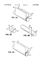
FIGS. 3A, 3B, 3C and 3D are somewhat diagrammatic perspective views of a sequence of steps for forming a composite sandwich element of the invention in the form of a duct, using a table wrap method, where FIG. 3A shows formation of a first (inner) wall, FIG. 3B shows a first method of formation of an intervening layer, FIG. 3C shows formation of a second (outer) wall, and FIG. 3D shows a second method of formation of the intervening layer.
FIG. 4 is a somewhat diagrammatic side view of the wall of the embodiment of a composite sandwich element of FIG. 2A;
FIG. 5 is a somewhat diagrammatic side view of the wall of another embodiment of a composite sandwich element of the invention;
FIG. 6 is a somewhat diagrammatic side view of the wall of still another embodiment of a composite sandwich element of the invention;
FIG. 7 is a somewhat diagrammatic side view of the wall of still another embodiment of a composite sandwich element of the invention; and
FIG. 8 is a somewhat diagrammatic side view of the wall of still another embodiment of a composite sandwich element of the invention.
FIGS. 9-18 are somewhat diagrammatic exploded side views of other embodiments of a composite sandwich element of the invention.
Referring to FIG. 1, the passenger compartment or pressure shell 2 of a modern commercial jet aircraft 4 is provided with improved structural, non-weight-bearing composite sandwich elements of the invention, including, e.g., air-conditioning duct 6, ceiling panels 8 and wall panels 10.
According to the invention, composite sandwich elements suitable for use within the passenger compartment of a commercial aircraft are formed, at least in part, of first and second walls formed of a web of random or oriented non-woven or woven glass fibers impregnated with a low heat release polymeric binder containing a chemical flame retardant, with an intervening layer of cellular polymeric foam disposed therebetween.
In the preferred embodiment, the polymeric binder used in composite sandwich element is a commercially available phenolic resin selected to have as low a heat release as possible. The fire retardant agents that are combined with the resin to form at least one of the walls may comprise one or more components that act to reduce the heat release rate in a manner common to the state-of-the-art. Examples of suitable fire retardant agents and/or compositions include aluminum trihydrate, zinc borate and similar chemicals.
The cellular polymeric material employed in the intervening layer is preferably formed of imide resin, in foamed or cellular state, which is known to have an exceedingly low heat release, e.g. as described below, and works in combination with the wall elements to maintain acceptably low levels of heat release in the composite sandwich element. The layer of cellular polymeric material serves also as a heat insulator for any variation of temperature across the composite sandwich element, and it serves as a sound insulator to reduce the acoustic level across the composite sandwich element.
Referring to FIG. 2, a composite sandwich element 12 of the invention has a first wall 14 and a second wall 16, with an intervening layer 18 of cellular foam or felt disposed therebetween. Referring to FIG. 2A, the inventors have found that in a composite sandwich element 12 of the invention, walls 14, 16 each consisting of a non-woven web 20 of fibrous material, e.g., filament glass fibers 22, provides a relatively high void volume, with a substantially greater number of interstitial spaces or voids 24 (as compared to woven fabrics) within which the phenolic resin material 26 containing the chemical flame retardant 28 may be retained. The comparatively high resin content of the non-woven material imparts a relatively greater stiffness, e.g. as compared to the relatively lower stiffness of woven glass as a result of its lesser ability to hold resin.
Still referring to FIG. 2A, for improved strength, the walls of this composite sandwich of the invention may include a layer of woven cloth or coarsely woven, grid-like scrim 30, e.g. also of fibrous material such as filament glass fibers 32, as an inert, strengthening element. The scrim 30 is also impregnated with phenolic resin 34.
The glass fibers carry the volume of polymeric binder necessary to provide desired levels of stiffness, strength and integrity in the walls of the composite sandwich element, while the binder can also contain a fire retardant to reduce the heat release rate. The non-woven material has a high void volume which provides sufficient space in the fiber network for the polymeric binder and necessary fire retardants. The fibers in the non-woven sheet are not interconnected, e.g. as in woven cloth, which permits the fibers to move, e.g. with a mold, to conform to complex mold features, including, e.g., double curved contours and sharper radii, under pressure and/or heat during molding operations.
A thin layer of polymeric film 36, e.g. polyvinylidene fluoride or nylon film about 0.001 to 0.002 inch thick, renders the composite wall impermeable to flow of air (reduced air impermeability, or complete impermeability to air, is desirable in construction of ducts). The film is selected to bond to other components of the composite that are impregnated or coated with phenolic resin upon application of heat and pressure during the molding operation. The polymeric film, e.g., polyvinylidene fluoride, may be given a primer coat of phenolic resin to enhance mechanical bonding. The nylon film is known to solvate with the phenolic interface of the adjacent pre-preg layer to form a chemical bond that improves most mechanical properties, providing, e.g., improved flexing, impact and shatter resistance, and hoop strength; however, it is important to limit the degree of solvation in order to maintain a desired level of impermeability.
A layer of metallic film 38, e.g. an aluminum film 0.0007 to 0.0016 inch thick, can be included to render the wall impermeable and to reflect heat, thus lowering the heat release characteristics of the composite sandwich element. The metallic film may also be given a primer coat of phenolic resin to enhance mechanical bonding.
The composite sandwich element of the invention demonstrates both a low level of flammability (burn resistance) and a low heat release rate compatible with its planned final application within the pressure shell of a modern jet aircraft. In addition, all of the components of the composite sandwich element were chosen to demonstrate low toxicity of gases emitted by combustion. Methods for evaluation of composite sandwich elements, and the performance of the composite sandwich element of the invention, are described and quantified below.
Referring now to FIGS. 3A, 3B and 3C (and also to FIG. 3D), according to one aspect of the invention, an aircraft air-conditioning duct 6 of the invention can be fabricated by winding, onto a mandrel, strips that are equal in width to the mandrel length. In this manner, the first (inner) wall 14 of the composite is built up onto the mandrel by successive wraps (i.e., a "table wrap" method). In particular, referring to FIG. 3A, the first layer 104 applied about the mandrel 102 is a thin polymeric, i.e. nylon, film, which in this embodiment of an aircraft air-conditioning duct, also provides air impermeability. A strengthening layer 106 of phenolic resin impregnated woven scrim is applied over the nylon layer 104, and a non-woven/phenolic resin "pre-preg" layer 108 is applied over the scrim.
Referring next to FIG. 3B, the intervening layer 18 is formed upon the first wall 14 by providing one or more thin sheets of 110 of cellular or foamed imide resin which are placed about the wall 14 on mandrel 102. The sheets 110 may be spiral wound about the wall 14, as shown in FIG. 3B, or long thin sheets 112 may be placed about the wall 14 in the fashion of barrel staves (FIG. 3D).
Referring next to FIG. 3C, the second (outer) wall 16 is built up onto the intervening layer 18 by successive wraps (i.e., a "table wrap" method), in the manner of the first wall 14, described above. In particular, a non-woven/phenolic resin "pre-preg" layer 114 is applied over the layer 18, and a strengthening layer 116 of phenolic resin impregnated woven scrim is applied over the layer 114. A further layer 118 applied about the layer 116 is a thin metallic, i.e. aluminum, film, which in this embodiment of an aircraft air-conditioning duct, also provides reflection of heat and air impermeability.
The layers of polymeric and metallic film may be disposed at other positions within the composite sandwich element. However, in formation of a duct by the mandrel process just described, it is preferred to place the nylon film at a position to form the interior wall of the duct. In this position, the nylon film greatly aids in the release of the completed cured duct from the tooling or mandrel upon which it is formed. In the completed duct, it also provides a smooth surface desirable for flow of air within the duct. Also, where the composite sandwich element is a relatively thin wall duct, it is anticipated that the polymeric film will serve to further lower the level of sound produced by flow of air within the duct. A polymeric film may also limit absorption of water into the duct wall, although it is questionable whether a polymeric film of nylon will have an appreciable advantageous effect in this regard.
The metallic film 118 is typically incorporated into the composite sandwich element in instances where a very low level of heat release is desired. In the case of a fire, the metallic film will reflect a large segment of the exterior heat, and incorporation of the metallic film into the composite duct of the invention will further lower the heat release rate, i.e. beyond the level obtained with the fire retardants incorporated within the phenolic resin binder. The metallic film may be employed to particular advantage when incorporated at or near the outer surface of the duct. If the polymeric film is used in conjunction with the metallic film, the polymeric film is preferably disposed at a side of the metallic film opposite the side most likely to face a source of heat or fire.
The composite sandwich element is treated by heat, typically while still upon the mandrel 102, e.g. to cause chemical bonding between the nylon and phenolic resin, and also between the phenolic resin and the polyvinylidene fluoride, resulting in a duct 6 with very low weight, but high heat resistance, elasticity and resistance to impact. More importantly, performance of the composite material of the duct in the presence of fire more than exceeds the requirements for passenger safety established by the F.A.A.
Composite sandwich elements of the invention are formed with any of a number of combinations of materials using glass fibers, in woven, non-woven or scrim form, and a metallic film and/or a polymeric film.
The fiberglass woven cloth and fiberglass non-woven mat are saturated with phenolic resin containing appropriate amounts of suitable, state-of-the-art fire retardant chemicals, e.g. aluminum trihydrate, zinc borate or the like. The finished, cured, resinated fiberglass woven cloth used to form the walls of the composite sandwich element contains approximately 30 to 55% (by weight) phenolic resin. The finished, cured, resinated fiberglass non-woven mat of the walls of the composite sandwich element contains approximately 60 to 85% (by weight) phenolic resin.
The following are typical material combinations that might be employed in formation of the walls of a composite sandwich element in the form of an air-conditioning duct of aircraft.
Referring to FIG. 4, layer 1 (the outermost layer) is a woven glass cloth 0.008 inch thick, 24×16 and 5.2 oz/yd2 (e.g., Style 1964 Woven glass tape, available from Mutual Industries of Philadelphia, Pa.). Layer 2 is a fiberglass non-woven mat 1.4 oz/yd2 (e.g., Ultra-Mat No. 83095A, available from Elk Corporation of Ennis, Tex.). Layer 3 is a metallic aluminum film 0.001 inch thick (e.g., available from Reynolds Metal Co. of Richmond, Va.). Layer 4 is also a fiberglass non-woven mat 1.4 oz/yd2 (e.g., Ultra-Mat No. 83095A, Elk Corporation), and layer 5 (the innermost layer) is also a woven glass cloth 0.008 inch thick, 24×16 and 5.2 oz/yd2 (e.g., Style 1964 Woven glass tape, Mutual Industries).
Referring to FIG. 5, layer 1 (the outermost layer) is a woven glass cloth 0.008 inch thick, 24×16 and 5.2 oz/yd2 (e.g., Style 1964 Woven glass tape, Mutual Industries). Layer 2 is a fiberglass non-woven mat 1.4 oz/yd2 (e.g., Ultra-Mat No. 83095A, Elk Corporation). Layer 3 is a polymeric nylon film 0.001 inch thick (e.g., available from Richmond Aircraft Products of Norwalk, Conn.). Layer 4 is also a fiberglass non-woven mat 1.4 oz/yd2 (e.g., Ultra-Mat No. 83095A, Elk Corporation), and layer 5 (the innermost layer) is also a woven glass cloth 0.008 inch thick, 24×16 and 5.2 oz/yd2 (e.g., Style 1964 Woven glass tape, Mutual Industries).
Referring to FIG. 6, layer 1 (the outermost layer) is a woven glass cloth 0.008 inch thick, 24×16 and 5.2 oz/yd2 (e.g., Style 1964 Woven glass tape, Mutual Industries). Layer 2 is a fiberglass non-woven mat 1.4 oz/yd2 (e.g., Ultra-Mat No. 83095A, Elk Corporation). Layer 3 is also woven glass cloth 0.008 inch thick, 24×16 and 5.2 oz/yd2 (e.g., Style 1964 Woven glass tape, Mutual Industries). Layer 4 (the innermost layer) is a polymeric nylon film 0.001 inch thick (e.g., available from Richmond Aircraft Products).
Referring to FIG. 7, layer 1 (the outermost layer) is a fiberglass non-woven mat 1.4 oz/yd2 (e.g., Ultra-Mat No. 83095A, Elk Corporation). Layer 2 is aluminum film 0.001 inch thick (e.g., available from Reynolds Metal Co.). Layer 3 is also a fiberglass non-woven mat 1.4 oz/yd2 (e.g., Ultra-Mat No. 83095A), and layer 4 is also a woven glass cloth 0.008 inch thick, 24×16 and 5.2 oz/yd2 (e.g., Style 1964 Woven glass tape, Mutual Industries). Layer 5 (the innermost layer) is a polymeric nylon film 0.001 inch thick (e.g., available from Richmond Aircraft Products).
Referring now to FIG. 8, a composite sandwich element consists of a center layer A formed of a single or multiple layers of a rigid or semi-rigid foam with a polymeric coating applied at the two extreme outer surfaces, a', a".
In this example, the foam layer A is a single layer of 0.25 inch thick imide foam having a density of 5 lbs./ft3. Coating layers B, C applied to each side surface of the foam are a phenolic resin containing appropriate amounts of suitable, state-of-the-art fire retardant chemicals including as examples aluminum trihydrate and zinc borate. The coating layers B, C were applied in a manner to control the amount applied and the depth to which the coating material penetrated into the foam (lines D, D').
One or more layers of a reinforcing fibers network (woven or nonwoven) may be applied to an outer surface or surfaces of the foam, either before, during or after application of the phenolic resin. In this example, a fiber network E at the first surface a' consisted of a woven fiberglass scrim laid onto the outer surface of the coated foam with the resin coating B in the wet state prior to cure, and a fiber network F at the second surface a" consisted of a woven glass cloth similarly applied to the opposite outer surface of the coated foam, again with the resin coating C in wet state prior to cure.
In this example, to provide additional protection and/or decoration, a sheet of TEDLAR™ polyvinylidene fluoride film G was placed against the outer surface of the foam having the woven glass cloth F in place on the resin coating.
The resulting laminate of glass scrim E, resin coating (with flame retardant) B, imide foam A, resin coating (with flame retardant) C, woven glass F and TEDLAR™ film G was then placed in a press and heat and pressure were applied to effect a resin cure and a bond to integrate all of the components of the composite sandwich element.
The composite sandwich element can then be molded to a flat or curved plane, as desired.
The composite sandwich elements formed according to the examples were evaluated using the test methods described for performance in the presence of fire. The composite sandwich elements of the invention exhibited levels of heat release, flammability, smoke release and toxic gas release below predetermined levels considered suitable for use within the passenger compartment of a commercial aircraft.
In particular, composite sandwich elements of the invention had a typical peak heat release rate of less than 50 kw/m2 (and typically less than 45 kw/m2) and a two minute heat release of less than 50 kw-min/m2 (and typically less than 45 kw-min/m2), when tested in accordance with the requirements of FAR 25.853(a-1) through Amendment 25-66 and FAR 121.312(a)(1) through Amendment 121-198. Furthermore, those composite sandwich elements of the invention including a metallic barrier film, when tested in the same manner, exhibited a typical peak heat release rate of less than about 30 kw/m2 and a two minute heat release of less than about 30 kw-min/m2. By way of comparison, the maximum peak heat release permitted by the FAA is 65 kw/m2 and the maximum two minute heat release permitted by the FAA is 65 kw-min/m2.
Composite sandwich elements of the invention were also tested for flammability, using the vertical flammability tests specified in FAR 25.853(a) and FAR 25.853(b). The composite sandwich elements of the invention had a burn length of less than 1.0 inch after 60 seconds. Again, by way of comparison, the maximum burn length permitted by the FAA is 6.0 inches after 60 seconds.
Composite sandwich elements of the invention were also tested for the level of smoke release, measured as specific optical density (Ds), in accordance with the requirements of FAR 25.853(a-1) through Amendment 25-66 and FAR 121.132 through Amendment 121-198. The composite sandwich elements of the invention exhibited a typical (four minute) specific optical density (4 Dm) of 75 or less. In contrast, the average maximum specific optical density (4 Dm) permitted by a major U.S. aircraft manufacturer is 150, while the FAA standard is 200.
In air permeability testing, a typical composite sandwich element of the invention including a barrier layer of polymeric film shows negligible air flow through the wall at a pressure differential of 20 psi.
Composite sandwich elements of the invention also typically exhibit tensile strength of at least 18,000 psi, and burst strength of greater that 30 psi.
Composite sandwich elements in the form of lower weight ducts (e.g. 1 oz/ft/in ID) also typically satisfy appropriate requirements for span load testing, compress-to-break testing and impact testing.
Composite sandwich elements of the configurations shown in FIGS. 9-18 were tested in accordance with the requirements of FAR 25.853(a-1) through Amendment 25-66 and FAR 121.312(a)(1) through Amendment 121-198 and exhibited the typical peak heat release rate (measured in kw/m2) and two minute heat release (measured in kw-min/m2) shown in the Table 1 and Table 2 below.
              TABLE 1
______________________________________
                 Peak Heat  Two Minute
Configuration    Release Rate
                            Heat Release
______________________________________
Insulating layer 15         11
only [FIG. 9]
Polymeric film/  21         12
insulating layer [FIG. 10]
Polymeric film/insulating
                 21         20
layer/polymeric film
[FIG. 11]
Insulating layer/polymeric
                 17          3
film/insulating layer
[FIG. 12]
Glass cloth/polymeric film/
                 29         23
glass cloth/insulating
layer/glass cloth [FIG. 13]
Glass strips/polymeric film/
                 27         31
glass strips/insulating layer/
glass strips/polymeric film/
glass strips [FIG. 14]
Glass strips/polymeric film/
                 26         18
glass strips/insulating layer/
insulating layer/glass strips/
polymeric film/glass strips
[FIG. 15]
______________________________________
(As mentioned above, and by way of comparison, the maximum peak heat release permitted by the FAA is 65 kw/m2 and the maximum two minute heat release permitted by the FAA is 65 kw-min/m2.)
The composite sandwich elements shown in FIGS. 9-15 (and represented in Table 1, above) include one or more of the following layers: a layer of insulating material 50 (polyimide foam about 0.187 inch thick, e.g., available from Imi-Tech Corporation), a polymeric film 52 (polyvinylidene fluoride film 0.001 inch thick, e.g., TEDLAR™ film available from DuPont), a layer of phenolic resin impregnated glass cloth sheets 54 (0.020 inch thick), and/or a layer of resin impregnated glass cloth strips 56 (0.020 inch thick). The direction of application of the flame is indicated by the arrow. The layers are listed in Table 1 in the direction moving away from the flame.
              TABLE 2
______________________________________
                 Peak Heat  Two Minute
Configuration    Release Rate
                            Heat Release
______________________________________
Insulating layer 15         11
only [FIG. 16]
Metallic foil/    4         2
insulating layer [FIG. 17]
Glass cloth/metallic foil/
                 15         8
glass cloth/insulating
layer/glass cloth [FIG. 18]
______________________________________
The composite sandwich elements shown in FIGS. 16-18 (and represented in Table 2, above) include one or more of the following layers: a layer of insulating material 60 (polyimide foam about 0.187 inch thick, e.g., available from Imi-Tech Corporation), a layer of phenolic resin impregnated glass cloth sheets 62 (0.020 inch thick), and/or a layer of metallic film 64 (aluminum film 0.001 inch thick, e.g., available from Reynolds Metal Co. of Richmond, Va.). Again, the direction of application of the flame is indicated by the arrow. The layers are also listed in Table 2 in the direction moving away from the flame.
Other embodiments are within the following claims. For example, composite sandwich elements of the invention may be employed in the form of other structural, non-weight bearing elements of an aircraft passenger compartment, e.g. wall and ceiling panels. In these and other embodiments, the order of the composite layers may be varied as desired according to the desired application. For example, in wall panels, where the non-woven layer is to be the passenger compartment side of the panel for reasons of appearance, the metallic film may be applied upon the nylon film, e.g. as the opposite surface layer, in order to better retard penetration of heat into the passenger compartment in the event of a fire.
Other materials suitable for sound and/or thermal insulation may be substituted for the cellular polymeric foam.
Also, multiple layers of non-woven and/or woven pre-preg material may be employed for adding bulk to the composite sandwich element, and thus increasing wall thickness and stiffness, where such characteristics are desired.
Although the foregoing describes several embodiments of a composite sandwich element of the invention, it is understood that the invention may be practiced in still other forms, including but not limited to with greater or fewer layers, still within the scope of the following claims. For example, the concept of the invention may be employed also in underwater environments, i.e. in submarines, with similar performance requirements for heat release, flammability, smoke release and/or toxic gas release.
Claims (18)
1. A composite sandwich element comprising:
at least one wall layer comprising a fibrous web impregnated with a phenolic resin binder, said fibrous web having a sufficiently high void volume to carry a volume of said phenolic resin binder sufficient to provide said composite sandwich element with structural integrity, and
a layer consisting essentially of cellular polymeric foam or felt of imide polymeric material bonded to a surface of said at least one wall layer.
2. The composite sandwich element of claim 1 wherein said fibrous web comprises glass fibers.
3. The composite sandwich element of claim 1 further comprising a second wall layer, wherein said layer of cellular polymeric foam or felt is disposed between said first wall layer and said second wall layer.
4. The composite sandwich element of claim 1, further comprising a barrier film adapted to render said composite sandwich element impermeable to air.
5. The composite sandwich of claim 4 wherein the maximum flow of air through the composite sandwich, with a pressure differential of 20 psi thereacross, does not exceed 0.005 ft3 /min/ft2.
6. The composite sandwich element of claim 4 wherein said barrier film comprises a polymeric film.
7. The composite sandwich element of claim 6 wherein said polymeric film consists essentially of polyvinylidene fluoride.
8. The composite sandwich element of claim 4 or 6 wherein said barrier film comprises a metallic film.
9. The composite sandwich element of claim 8 wherein said metallic film consists essentially of aluminum.
10. The composite sandwich element of claim 1 wherein said phenolic resin binder comprises chemical agents adapted to reduce the rate of heat release, and
said layer of cellular polymeric foam or felt of imide polymeric material is at least about 0.100 inch thick.
11. The composite sandwich element of claim 10 wherein said chemical agents adapted to reduce the rate of heat release are selected from the group consisting of aluminum trihydrate and zinc borate.
12. The composite sandwich element of claim 10 or having a peak heat release rate of less than 50 kw/m2 and a two minute heat release of less than 50 kw-min/m2 when tested in accordance with the requirements of FAR 25.853(a-1) through Amendment 25-66 and FAR 121.312(a)(1) through Amendment 121-198.
13. The composite sandwich element of claim 12 wherein said peak heat release rate is less than 45 kw/m2 and said two minute heat release of less than 45 kw-min/m2.
14. The composite sandwich element of claim 1 wherein said fibrous web is a non-woven web.
15. The composite sandwich element of claim 14 wherein said non-woven web comprises glass fibers.
16. The composite sandwich element of claim 1 wherein said fibrous web is a woven cloth.
17. The composite sandwich element of claim 16 wherein said woven cloth comprises glass cloth.
18. A composite sandwich element having levels of heat release, flammability, smoke release and toxic gas release below predetermined levels considered suitable for use within the passenger compartment of a commercial aircraft, said sandwich element comprising:
at least one wall layer comprising a fibrous web impregnated with a phenolic resin binder, said fibrous web having a sufficiently high void volume to carry a volume of said phenolic resin binder sufficient to provide said composite sandwich element with structural integrity, and
a layer of cellular polymeric foam or felt of imide polymeric material bonded to a surface of said at least one wall layer, and
a metallic barrier film, selected and positioned to render said composite sandwich element impermeable to air, bonded to a portion of said composite element.
Priority Applications (4)
| Application Number | Priority Date | Filing Date | Title |
|---|---|---|---|
| US08/177,562 US5527598A (en) | 1993-05-05 | 1994-01-05 | Composite sandwich element |
| PCT/US1994/004684 WO1994025180A1 (en) | 1993-05-05 | 1994-04-28 | Composite sandwich element |
| CA 2162171 CA2162171A1 (en) | 1993-05-05 | 1994-04-28 | Composite sandwich element |
| US08/394,469 US5712017A (en) | 1993-05-05 | 1995-02-27 | Composite materials comprising a plurality of resin impregnated felt layers |
Applications Claiming Priority (2)
| Application Number | Priority Date | Filing Date | Title |
|---|---|---|---|
| US5762093A | 1993-05-05 | 1993-05-05 | |
| US08/177,562 US5527598A (en) | 1993-05-05 | 1994-01-05 | Composite sandwich element |
Related Parent Applications (1)
| Application Number | Title | Priority Date | Filing Date |
|---|---|---|---|
| US5762093A Continuation-In-Part | 1993-05-05 | 1993-05-05 |
Related Child Applications (1)
| Application Number | Title | Priority Date | Filing Date |
|---|---|---|---|
| US08/394,469 Continuation-In-Part US5712017A (en) | 1993-05-05 | 1995-02-27 | Composite materials comprising a plurality of resin impregnated felt layers |
Publications (1)
| Publication Number | Publication Date |
|---|---|
| US5527598A true US5527598A (en) | 1996-06-18 |
Family
ID=22011733
Family Applications (1)
| Application Number | Title | Priority Date | Filing Date |
|---|---|---|---|
| US08/177,562 Expired - Fee Related US5527598A (en) | 1993-05-05 | 1994-01-05 | Composite sandwich element |
Country Status (3)
| Country | Link |
|---|---|
| US (1) | US5527598A (en) |
| CA (1) | CA2161137A1 (en) |
| WO (1) | WO1994025267A1 (en) |
Cited By (17)
| Publication number | Priority date | Publication date | Assignee | Title |
|---|---|---|---|---|
| US5918644A (en) * | 1996-05-23 | 1999-07-06 | Haack; C. William | Air duct and method of making same |
| US20030031854A1 (en) * | 2001-08-07 | 2003-02-13 | Kajander Richard Emil | Method of making coated mat online and coated mat products |
| GB2389336A (en) * | 2002-06-08 | 2003-12-10 | Cons Fiberglass Products Compa | In line faced marine insulation and method of production |
| US6723670B2 (en) | 2001-08-07 | 2004-04-20 | Johns Manville International, Inc. | Coated nonwoven fiber mat |
| US6749929B1 (en) * | 1998-05-14 | 2004-06-15 | Hp-Chemie Pelzer Research And Development Ltd. | Heat-insulating and soundproofing lining for an engine compartment of a motor vehicle |
| US20040177579A1 (en) * | 2003-03-10 | 2004-09-16 | Innovative Construction Technologies, Inc. | Reinforced foam articles |
| US20040177580A1 (en) * | 2003-03-10 | 2004-09-16 | Innovative Construction Technologies, Inc. | Reinforced foam articles |
| US20050064174A1 (en) * | 2003-09-18 | 2005-03-24 | The Boeing Company | Reaction injection molded members and method of forming |
| US6914020B1 (en) * | 1999-02-09 | 2005-07-05 | Moeller Tech Gmbh | Sound and heat insulation material |
| US20060189236A1 (en) * | 2005-02-18 | 2006-08-24 | Davis George K | Fire-resistant ultra-lightweight panel with three-dimensional surface design |
| US20060234027A1 (en) * | 2005-04-18 | 2006-10-19 | Huusken Robert W | Fire retardant laminate |
| US20060234026A1 (en) * | 2005-04-18 | 2006-10-19 | Huusken Robert W M | Non-combustible high pressure laminate |
| US20120040599A1 (en) * | 2010-08-11 | 2012-02-16 | Diehl Aircabin Gmbh | Sandwich board for an inner wall cladding of a passenger cabin |
| JP2012522677A (en) * | 2009-04-01 | 2012-09-27 | エアバス・オペレーションズ・ゲゼルシャフト・ミット・ベシュレンクテル・ハフツング | Body segment and method for manufacturing body segment |
| CZ306517B6 (en) * | 2014-02-04 | 2017-02-22 | Výzkumný a zkušební letecký ústav, a.s. | A transparent mould for repeated precision casting, made of a composite material |
| US11192338B2 (en) | 2017-10-12 | 2021-12-07 | Tredegar Surface Protection, Llc | Films for use as interleaves between substrates |
| US11958308B1 (en) | 2023-05-31 | 2024-04-16 | G13 Innovation In Production Ltd | Thermal paper, and methods and systems for forming the same |
Families Citing this family (1)
| Publication number | Priority date | Publication date | Assignee | Title |
|---|---|---|---|---|
| US6554936B1 (en) * | 1999-09-08 | 2003-04-29 | Alliant Techsystems Inc. | Method of constructing insulated metal dome structure for a rocket motor |
Citations (17)
| Publication number | Priority date | Publication date | Assignee | Title |
|---|---|---|---|---|
| US3779854A (en) * | 1971-06-18 | 1973-12-18 | Pennwalt Corp | Polyvinylidene fluoride laminate construction and method |
| US4054711A (en) * | 1973-07-16 | 1977-10-18 | Johns-Manville Corporation | Composite insulation jacket |
| US4186044A (en) * | 1977-12-27 | 1980-01-29 | Boeing Commercial Airplane Company | Apparatus and method for forming laminated composite structures |
| US4342810A (en) * | 1981-03-23 | 1982-08-03 | Sheller-Globe Corporation | Plastic core composite having improved impact resistance |
| US4499145A (en) * | 1982-04-19 | 1985-02-12 | Sumitomo Bakelite Company Limited | Metal-clad laminate and process for producing the same |
| US4557961A (en) * | 1983-05-27 | 1985-12-10 | The Boeing Company | Light-weight, fire-retardant structural panel |
| US4567092A (en) * | 1982-10-11 | 1986-01-28 | Scal Societe De Conditionnements En Aluminium | Composite material and its application to reinforcement in insulating panels |
| US4818603A (en) * | 1987-11-12 | 1989-04-04 | Ethyl Corporation | Thermal-acoustic insulation composite panel |
| US4874648A (en) * | 1988-03-17 | 1989-10-17 | Sorrento Engineer, Inc. | Method of making flame resistant polyimide foam insulation and the resulting insulation |
| US4883708A (en) * | 1987-06-04 | 1989-11-28 | Shin-Kobe Electric Machinery Co., Ltd. | Metal foil covered laminate |
| US4915998A (en) * | 1988-08-24 | 1990-04-10 | International Fuel Cells Corporation | Thermal insulation blanket |
| US4923741A (en) * | 1988-06-30 | 1990-05-08 | The United States Of America As Represented By The Administrator, National Aeronautics And Space Administration | Hazards protection for space suits and spacecraft |
| US4960633A (en) * | 1986-04-22 | 1990-10-02 | The Yokohama Rubber Co., Ltd. | Microwave-absorptive composite |
| US4978572A (en) * | 1987-10-05 | 1990-12-18 | Fuji Photo Film Co., Ltd. | Laminated film |
| US5017429A (en) * | 1987-05-15 | 1991-05-21 | Fuji Photo Film Co., Ltd. | Packaging material for photosensitive materials |
| US5110668A (en) * | 1990-12-21 | 1992-05-05 | General Electric Company | Flexible laminate having copolyetherester adhesive |
| US5229184A (en) * | 1988-04-14 | 1993-07-20 | Albany International Corporation | Heat shrinkable fibres and products therefrom |
-
1994
- 1994-01-05 US US08/177,562 patent/US5527598A/en not_active Expired - Fee Related
- 1994-04-26 WO PCT/US1994/004528 patent/WO1994025267A1/en active Application Filing
- 1994-04-26 CA CA002161137A patent/CA2161137A1/en not_active Abandoned
Patent Citations (17)
| Publication number | Priority date | Publication date | Assignee | Title |
|---|---|---|---|---|
| US3779854A (en) * | 1971-06-18 | 1973-12-18 | Pennwalt Corp | Polyvinylidene fluoride laminate construction and method |
| US4054711A (en) * | 1973-07-16 | 1977-10-18 | Johns-Manville Corporation | Composite insulation jacket |
| US4186044A (en) * | 1977-12-27 | 1980-01-29 | Boeing Commercial Airplane Company | Apparatus and method for forming laminated composite structures |
| US4342810A (en) * | 1981-03-23 | 1982-08-03 | Sheller-Globe Corporation | Plastic core composite having improved impact resistance |
| US4499145A (en) * | 1982-04-19 | 1985-02-12 | Sumitomo Bakelite Company Limited | Metal-clad laminate and process for producing the same |
| US4567092A (en) * | 1982-10-11 | 1986-01-28 | Scal Societe De Conditionnements En Aluminium | Composite material and its application to reinforcement in insulating panels |
| US4557961A (en) * | 1983-05-27 | 1985-12-10 | The Boeing Company | Light-weight, fire-retardant structural panel |
| US4960633A (en) * | 1986-04-22 | 1990-10-02 | The Yokohama Rubber Co., Ltd. | Microwave-absorptive composite |
| US5017429A (en) * | 1987-05-15 | 1991-05-21 | Fuji Photo Film Co., Ltd. | Packaging material for photosensitive materials |
| US4883708A (en) * | 1987-06-04 | 1989-11-28 | Shin-Kobe Electric Machinery Co., Ltd. | Metal foil covered laminate |
| US4978572A (en) * | 1987-10-05 | 1990-12-18 | Fuji Photo Film Co., Ltd. | Laminated film |
| US4818603A (en) * | 1987-11-12 | 1989-04-04 | Ethyl Corporation | Thermal-acoustic insulation composite panel |
| US4874648A (en) * | 1988-03-17 | 1989-10-17 | Sorrento Engineer, Inc. | Method of making flame resistant polyimide foam insulation and the resulting insulation |
| US5229184A (en) * | 1988-04-14 | 1993-07-20 | Albany International Corporation | Heat shrinkable fibres and products therefrom |
| US4923741A (en) * | 1988-06-30 | 1990-05-08 | The United States Of America As Represented By The Administrator, National Aeronautics And Space Administration | Hazards protection for space suits and spacecraft |
| US4915998A (en) * | 1988-08-24 | 1990-04-10 | International Fuel Cells Corporation | Thermal insulation blanket |
| US5110668A (en) * | 1990-12-21 | 1992-05-05 | General Electric Company | Flexible laminate having copolyetherester adhesive |
Cited By (23)
| Publication number | Priority date | Publication date | Assignee | Title |
|---|---|---|---|---|
| US5918644A (en) * | 1996-05-23 | 1999-07-06 | Haack; C. William | Air duct and method of making same |
| US6749929B1 (en) * | 1998-05-14 | 2004-06-15 | Hp-Chemie Pelzer Research And Development Ltd. | Heat-insulating and soundproofing lining for an engine compartment of a motor vehicle |
| US6914020B1 (en) * | 1999-02-09 | 2005-07-05 | Moeller Tech Gmbh | Sound and heat insulation material |
| US20030031854A1 (en) * | 2001-08-07 | 2003-02-13 | Kajander Richard Emil | Method of making coated mat online and coated mat products |
| US7285183B2 (en) | 2001-08-07 | 2007-10-23 | Johns Manville | Making foam coated mats on-line |
| US6723670B2 (en) | 2001-08-07 | 2004-04-20 | Johns Manville International, Inc. | Coated nonwoven fiber mat |
| US7220689B1 (en) | 2002-06-08 | 2007-05-22 | Upf Corporation | In line faced marine insulation, and method of production |
| GB2389336B (en) * | 2002-06-08 | 2005-06-22 | Cons Fiberglass Products Compa | In line faced marine insulation and method of production |
| GB2389336A (en) * | 2002-06-08 | 2003-12-10 | Cons Fiberglass Products Compa | In line faced marine insulation and method of production |
| US20040177579A1 (en) * | 2003-03-10 | 2004-09-16 | Innovative Construction Technologies, Inc. | Reinforced foam articles |
| US20040177580A1 (en) * | 2003-03-10 | 2004-09-16 | Innovative Construction Technologies, Inc. | Reinforced foam articles |
| WO2005028190A1 (en) * | 2003-09-18 | 2005-03-31 | The Boeing Company | Reaction injection molded members and method of forming |
| US20050064174A1 (en) * | 2003-09-18 | 2005-03-24 | The Boeing Company | Reaction injection molded members and method of forming |
| US20060189236A1 (en) * | 2005-02-18 | 2006-08-24 | Davis George K | Fire-resistant ultra-lightweight panel with three-dimensional surface design |
| WO2006091207A1 (en) * | 2005-02-18 | 2006-08-31 | Kalogridis International, Ltd. | Fire-resistant ultra-lightweight panel with three-dimensional surface design |
| US9598861B2 (en) | 2005-02-18 | 2017-03-21 | George Kalogridis Davis | Fire-resistant ultra-lightweight panel with three-dimensional surface design |
| US20060234026A1 (en) * | 2005-04-18 | 2006-10-19 | Huusken Robert W M | Non-combustible high pressure laminate |
| US20060234027A1 (en) * | 2005-04-18 | 2006-10-19 | Huusken Robert W | Fire retardant laminate |
| JP2012522677A (en) * | 2009-04-01 | 2012-09-27 | エアバス・オペレーションズ・ゲゼルシャフト・ミット・ベシュレンクテル・ハフツング | Body segment and method for manufacturing body segment |
| US20120040599A1 (en) * | 2010-08-11 | 2012-02-16 | Diehl Aircabin Gmbh | Sandwich board for an inner wall cladding of a passenger cabin |
| CZ306517B6 (en) * | 2014-02-04 | 2017-02-22 | Výzkumný a zkušební letecký ústav, a.s. | A transparent mould for repeated precision casting, made of a composite material |
| US11192338B2 (en) | 2017-10-12 | 2021-12-07 | Tredegar Surface Protection, Llc | Films for use as interleaves between substrates |
| US11958308B1 (en) | 2023-05-31 | 2024-04-16 | G13 Innovation In Production Ltd | Thermal paper, and methods and systems for forming the same |
Also Published As
| Publication number | Publication date |
|---|---|
| WO1994025267A1 (en) | 1994-11-10 |
| CA2161137A1 (en) | 1994-11-10 |
Similar Documents
| Publication | Publication Date | Title |
|---|---|---|
| US5527598A (en) | Composite sandwich element | |
| WO1994025180A1 (en) | Composite sandwich element | |
| US5667866A (en) | Multi-layered, unbalanced sandwich panel | |
| EP0144340B1 (en) | Acoustical structure and method of manufacturing it | |
| US6443257B1 (en) | Acoustical panel having a calendered, flame-retardant paper backing and method of making the same | |
| US4557970A (en) | Laminate structure with improved acoustical absorption | |
| US4476183A (en) | Thermoformable laminate structure with improved acoustical absorption | |
| US6711872B2 (en) | Lightweight panel construction | |
| US5622662A (en) | Method for forming a sound attenuation composite | |
| EP0146521B1 (en) | Laminate structure with improved acoustical absorption | |
| KR102018641B1 (en) | Dash insulator for vehicle having expandable foaming agent and method for manufacturing the same | |
| KR101558953B1 (en) | Heat insulator with advanced performance | |
| US20060013996A1 (en) | Laminated surface skin material and laminate for interior material | |
| US4335802A (en) | Sound absorbing material | |
| JP2555684B2 (en) | Flame retardant panel | |
| GB2101930A (en) | Self-supporting, generally flat construction element | |
| CN212453318U (en) | Honeycomb core material and composite honeycomb structure | |
| WO2019004151A1 (en) | Cover material for acoustic insulation, and engine unit | |
| JPH0887279A (en) | Sound absorbing body | |
| CN113123522A (en) | Honeycomb core material, method for manufacturing honeycomb core material, composite honeycomb structure, and method for manufacturing composite honeycomb structure | |
| JP6655569B2 (en) | Engine unit | |
| JPH10231568A (en) | Fireproof composite panel | |
| US20230159798A1 (en) | Flexible and low permeable vapor retardants for facing products | |
| CN218579383U (en) | Elevator car sound insulation structure | |
| JPH0611185Y2 (en) | Flame retardant composite insulation board |
Legal Events
| Date | Code | Title | Description |
|---|---|---|---|
| AS | Assignment |
Owner name: ALBANY INTERNATIONAL RESEARCH CO., MASSACHUSETTS Free format text: ASSIGNMENT OF ASSIGNORS INTEREST;ASSIGNORS:CAMPBELL, FREDERICK S.;BROWNELL, PETER;JORDAN, ROLAND E.;REEL/FRAME:006857/0078 Effective date: 19931230 |
|
| FPAY | Fee payment |
Year of fee payment: 4 |
|
| LAPS | Lapse for failure to pay maintenance fees | ||
| FP | Lapsed due to failure to pay maintenance fee |
Effective date: 20040618 |
|
| STCH | Information on status: patent discontinuation |
Free format text: PATENT EXPIRED DUE TO NONPAYMENT OF MAINTENANCE FEES UNDER 37 CFR 1.362 |