US5530208A - Pen computer pen gripping mechanism - Google Patents
Pen computer pen gripping mechanism Download PDFInfo
- Publication number
- US5530208A US5530208A US07/963,822 US96382292A US5530208A US 5530208 A US5530208 A US 5530208A US 96382292 A US96382292 A US 96382292A US 5530208 A US5530208 A US 5530208A
- Authority
- US
- United States
- Prior art keywords
- pen
- receptacle
- computer
- retention
- cutouts
- Prior art date
- Legal status (The legal status is an assumption and is not a legal conclusion. Google has not performed a legal analysis and makes no representation as to the accuracy of the status listed.)
- Expired - Fee Related
Links
Images


Classifications
-
- G—PHYSICS
- G06—COMPUTING; CALCULATING OR COUNTING
- G06F—ELECTRIC DIGITAL DATA PROCESSING
- G06F3/00—Input arrangements for transferring data to be processed into a form capable of being handled by the computer; Output arrangements for transferring data from processing unit to output unit, e.g. interface arrangements
- G06F3/01—Input arrangements or combined input and output arrangements for interaction between user and computer
- G06F3/03—Arrangements for converting the position or the displacement of a member into a coded form
- G06F3/033—Pointing devices displaced or positioned by the user, e.g. mice, trackballs, pens or joysticks; Accessories therefor
- G06F3/0354—Pointing devices displaced or positioned by the user, e.g. mice, trackballs, pens or joysticks; Accessories therefor with detection of 2D relative movements between the device, or an operating part thereof, and a plane or surface, e.g. 2D mice, trackballs, pens or pucks
- G06F3/03545—Pens or stylus
-
- G—PHYSICS
- G06—COMPUTING; CALCULATING OR COUNTING
- G06F—ELECTRIC DIGITAL DATA PROCESSING
- G06F1/00—Details not covered by groups G06F3/00 - G06F13/00 and G06F21/00
- G06F1/16—Constructional details or arrangements
- G06F1/1613—Constructional details or arrangements for portable computers
-
- G—PHYSICS
- G06—COMPUTING; CALCULATING OR COUNTING
- G06F—ELECTRIC DIGITAL DATA PROCESSING
- G06F1/00—Details not covered by groups G06F3/00 - G06F13/00 and G06F21/00
- G06F1/16—Constructional details or arrangements
- G06F1/1613—Constructional details or arrangements for portable computers
- G06F1/1626—Constructional details or arrangements for portable computers with a single-body enclosure integrating a flat display, e.g. Personal Digital Assistants [PDAs]
-
- G—PHYSICS
- G06—COMPUTING; CALCULATING OR COUNTING
- G06F—ELECTRIC DIGITAL DATA PROCESSING
- G06F2200/00—Indexing scheme relating to G06F1/04 - G06F1/32
- G06F2200/16—Indexing scheme relating to G06F1/16 - G06F1/18
- G06F2200/163—Indexing scheme relating to constructional details of the computer
- G06F2200/1632—Pen holder integrated in the computer
Definitions
- the present invention relates to the field of retention mechanisms for pen devices in pen computers.
- Portable pen computers characteristically include a large active screen area that is responsive to a pen or stylus device. Often, this pen or stylus device is especially adapted to cooperate with electronics within the screen so as to determine the position of the pen relative to the screen. This allows the user to effectively "write" data into the computer. Accordingly, it is important that the pen device be readily available to the user, as the pen computer may be inoperative without the corresponding specialized pen device.
- U.S. Pat. No. 4,927,986 issued to John J. Daly describes a pen computer having a tethered pen which is stored in a channel or groove located in the side of the computer. However, the pen is not readily visible from the top of the computer and the cord tether is undesirably cumbersome. Accordingly, a user cannot immediately determine whether the pen is present, and a novice may not be able to locate the pen at all.
- a pen computer in accordance with the preferred embodiment of the present invention includes a recess in the top surface adapted to resiliently retain a pen device.
- the pen is visible from the top, yet securely retained for storage and transport.
- the recession is proximate and parallel to one edge of the computer and includes an access notch which extends from the edge of the computer to the recession.
- the access notch is located near the center of the recession and is sized so that a user can grasp the pen and remove it from the resession by placing a finger in the access notch.
- Retention is provided by two resilient retention devices located near either end of the recession, which engage the pen above the centerline of the pen.
- FIG. 1 is a perspective drawing of a pen computer which incorporates the preferred embodiment of the pen gripping mechanism.
- FIG. 2 is a perspective drawing of a pen for use with the pen computer of FIG. 1.
- FIG. 3 is a near-actual size top view illustration of the top housing of pen computer 100 showing the portion of the top surface including receptacle 120.
- FIGS. 4 and 5 are two various perspective views of snap-in retention devices.
- FIG. 6 is a view of the inside (back) of the top housing of the pen computer illustrating the sides of the receptacle, which protrudes into the interior of the pen computer.
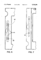
- FIG. 7 is another near-actual size top view illustration of the top housing of the pen computer showing the portion of the top surface including the receptacle wherein one of the snap-in retention devices has been removed to better illustrated the cutout.
- a pen computer 100 includes a display screen 110 and a receptacle 120 for holding a pen-type device.
- Receptacle 120 is parallel and proximate to the edge of pen computer 100, and includes an access notch 130 extending from the side of pen computer 100 sized to allow a user to grasp and remove a pen from the recession by placing a finger in access notch 130.
- Two retention devices 140 and 150 located near the ends of receptacle 120 resiliently retain a pen pressed into receptacle 120.
- FIG. 2 is a perspective drawing of a pen 200 for use with pen computer 100.
- Pen 200 is slightly shorter and narrower than receptacle 120 so that it fits easily into receptacle 120 without protruding significantly above the top surface of pen computer 100. This ensures that pen 200 is not inadvertently knocked loose from receptacle 120.
- FIG. 3 is a near-actual size top view illustration of the top housing of pen computer 100 showing the portion of the top surface including receptacle 120.
- receptacle 120 is parallel and proximate to the rounded edge 300 of pen computer 100, and includes an access notch 130 which extends from the side of pen computer 100 to recession 120.
- Access notch 130 is of the same depth as receptacle 120 and is sized to allow a user to easily grasp pen 200 from receptacle 120 by placing a finger in the cutout.
- Two snap-in retention devices 140 and 150 located near the ends of receptacle 120 resiliently retain pen 200 when pressed into receptacle 120.
- FIGS. 4 and 5 are various perspective views of resilient snap-in retention devices 140 (or the identical 150).
- Each snap-in retention device 140 (or 150) includes two hemispherical bumps 310 on the outside of the device and near the opposite ends for engagement with the housing of pen computer 100.
- Each snap-in retention device also includes two half-cylindrical bumps 320 on the inside of the device and above the centerline of receptacle 120. These bumps are resilient and shaped to firmly yet releaseably engage pen 200.
- FIG. 6 is a view of the inside (back) of the top housing of pen computer 100 illustrating the sides of receptacle 120, which protrudes into the interior of pen computer 100.
- Four alignment structures 410 are molded into the top housing of pen computer 100 and are aligned with two cutouts on the inside of receptacle 120 and include slots 420 adapted to receive hemispherical bumps 310 to align and help secure snap-in retention devices 140 and 150.
- FIG. 7 is another near-actual size top view illustration of the top housing of pen computer 100 showing the portion of the top surface including receptacle 120 wherein one of the snap-in retention devices has been removed to better illustrate a cutout 710.
- Cutout 710 has the same depth and general shape as a snap-in retention device and is positioned slightly below the top edge of pen computer 100.
- Snap-in retention device 140 is resilient. Thus, when pressed into cutout 710, snap-in retention devices 140 springs back to take the shape of cutout 710, snaps into place, and aligns with the edges of cutout 71 0 and slot 420.
- the top edges of snap-in retention devices 140 engage opposite facing surfaces in the top housing formed by cutout 71 0 and are firmly secured. (They can be removed by pressing the retention devices inward from the back through slots 420.)
- thermoplastic rubber is a suitable material for snap-in retention devices 140 and 150. The thermoplastic rubber compresses temporarily as pen device 200 is pressed into receptacle 120, then resiliently decompresses so as to releaseably retain pen device 200.
Abstract
A pen computer includes a recession in the top surface adapted to releaseably retain a pen device. The pen is visible from the top, yet securely retained for storage and transport. The recession is proximate and parallel to one edge of the computer and includes an access notch exteding rom the edge of the computer to the recession which is sized so that a user can grasp and remove the pen device from the recession by placing a finger in the access notch. Retention is by provided by two resilient retention devices near either end of the recession.
Description
1. Field
The present invention relates to the field of retention mechanisms for pen devices in pen computers.
2. Art Background
Portable pen computers characteristically include a large active screen area that is responsive to a pen or stylus device. Often, this pen or stylus device is especially adapted to cooperate with electronics within the screen so as to determine the position of the pen relative to the screen. This allows the user to effectively "write" data into the computer. Accordingly, it is important that the pen device be readily available to the user, as the pen computer may be inoperative without the corresponding specialized pen device. U.S. Pat. No. 4,927,986 issued to John J. Daly describes a pen computer having a tethered pen which is stored in a channel or groove located in the side of the computer. However, the pen is not readily visible from the top of the computer and the cord tether is undesirably cumbersome. Accordingly, a user cannot immediately determine whether the pen is present, and a novice may not be able to locate the pen at all.
Accordingly, it is desirable to provide a pen retention mechanism that makes the pen readily visible to the user while stored, securely retained during storage and transport, and readily accessible. Further, it is preferable that there be no cumbersome tether or cord.
A pen computer in accordance with the preferred embodiment of the present invention includes a recess in the top surface adapted to resiliently retain a pen device. The pen is visible from the top, yet securely retained for storage and transport. The recession is proximate and parallel to one edge of the computer and includes an access notch which extends from the edge of the computer to the recession. The access notch is located near the center of the recession and is sized so that a user can grasp the pen and remove it from the resession by placing a finger in the access notch. Retention is provided by two resilient retention devices located near either end of the recession, which engage the pen above the centerline of the pen.
This provides for retention of the pen in a secure position with little if any of the pen device protruding from the surface of the computer. The pen is readily visible and available, yet secure for storage and transport. Further, no cumbersome tether or cord is required. These and other advantages and features of the invention will become readily apparent to those skilled in the art after reading the following detailed description of the preferred embodiment of the present invention and studying the accompanying drawings.
FIG. 1 is a perspective drawing of a pen computer which incorporates the preferred embodiment of the pen gripping mechanism.
FIG. 2 is a perspective drawing of a pen for use with the pen computer of FIG. 1.
FIG. 3 is a near-actual size top view illustration of the top housing of pen computer 100 showing the portion of the top surface including receptacle 120.
FIGS. 4 and 5 are two various perspective views of snap-in retention devices.
FIG. 6 is a view of the inside (back) of the top housing of the pen computer illustrating the sides of the receptacle, which protrudes into the interior of the pen computer.
FIG. 7 is another near-actual size top view illustration of the top housing of the pen computer showing the portion of the top surface including the receptacle wherein one of the snap-in retention devices has been removed to better illustrated the cutout.
The preferred embodiment of the present invention is a pen gripping mechanism for a pen computer as illustrated in FIG. 1. As illustrated, a pen computer 100 includes a display screen 110 and a receptacle 120 for holding a pen-type device. Receptacle 120 is parallel and proximate to the edge of pen computer 100, and includes an access notch 130 extending from the side of pen computer 100 sized to allow a user to grasp and remove a pen from the recession by placing a finger in access notch 130. Two retention devices 140 and 150 located near the ends of receptacle 120 resiliently retain a pen pressed into receptacle 120.
FIG. 2 is a perspective drawing of a pen 200 for use with pen computer 100. Pen 200 is slightly shorter and narrower than receptacle 120 so that it fits easily into receptacle 120 without protruding significantly above the top surface of pen computer 100. This ensures that pen 200 is not inadvertently knocked loose from receptacle 120.
FIG. 3 is a near-actual size top view illustration of the top housing of pen computer 100 showing the portion of the top surface including receptacle 120. As illustrated, receptacle 120 is parallel and proximate to the rounded edge 300 of pen computer 100, and includes an access notch 130 which extends from the side of pen computer 100 to recession 120. Access notch 130 is of the same depth as receptacle 120 and is sized to allow a user to easily grasp pen 200 from receptacle 120 by placing a finger in the cutout. Two snap-in retention devices 140 and 150 located near the ends of receptacle 120 resiliently retain pen 200 when pressed into receptacle 120.
FIGS. 4 and 5 are various perspective views of resilient snap-in retention devices 140 (or the identical 150). Each snap-in retention device 140 (or 150) includes two hemispherical bumps 310 on the outside of the device and near the opposite ends for engagement with the housing of pen computer 100. Each snap-in retention device also includes two half-cylindrical bumps 320 on the inside of the device and above the centerline of receptacle 120. These bumps are resilient and shaped to firmly yet releaseably engage pen 200.
FIG. 6 is a view of the inside (back) of the top housing of pen computer 100 illustrating the sides of receptacle 120, which protrudes into the interior of pen computer 100. Four alignment structures 410 are molded into the top housing of pen computer 100 and are aligned with two cutouts on the inside of receptacle 120 and include slots 420 adapted to receive hemispherical bumps 310 to align and help secure snap-in retention devices 140 and 150.
FIG. 7 is another near-actual size top view illustration of the top housing of pen computer 100 showing the portion of the top surface including receptacle 120 wherein one of the snap-in retention devices has been removed to better illustrate a cutout 710. Cutout 710 has the same depth and general shape as a snap-in retention device and is positioned slightly below the top edge of pen computer 100. Snap-in retention device 140 is resilient. Thus, when pressed into cutout 710, snap-in retention devices 140 springs back to take the shape of cutout 710, snaps into place, and aligns with the edges of cutout 71 0 and slot 420. The top edges of snap-in retention devices 140 engage opposite facing surfaces in the top housing formed by cutout 71 0 and are firmly secured. (They can be removed by pressing the retention devices inward from the back through slots 420.)
Resilient snap-in retention devices 140 and 150 must snap into position and also releaseably engage pen device 200. We have found that thermoplastic rubber is a suitable material for snap-in retention devices 140 and 150. The thermoplastic rubber compresses temporarily as pen device 200 is pressed into receptacle 120, then resiliently decompresses so as to releaseably retain pen device 200.
While the invention has been particularly taught and described with reference to the preferred embodiment, those versed in the art will appreciate that minor modifications in form and details may be made without departing from the spirit and scope of the invention. For example, the description of the preferred embodiment describes a untethered pen device, but a tethered pen device could be accommodated by adapting the recession to appropriately accommodate the tether. Accordingly, all such modifications are embodied within the scope of this patent as properly come within my contribution to the art and are particularly pointed out by the following claims.
Claims (2)
1. A pen computer for use with a pen device, the pen computer having a receptacle in the top surface having a generally half-circular cross section and adapted to receive the pen device in a location visible from the top, the receptacle proximate and parallel to one edge of the computer and including an access notch extending from the near edge of the computer to the receptacle sized so that a user can grasp and remove the pen device from the receptacle by placing a finger in the access notch, the receptacle further including two cutouts, disposed towards opposite ends of the receptacle, and two pairs of vertical slots, two of the slots centered on each cutout, one slot on either side of the receptacle, and further including two resilient snap-in retention devices generally in the shape of sections of half-cylinders, the retention devices having the same depth and general shape as the cutouts such that the top edges of the retention devices snap-in and engage corresponding downward facing surfaces of the cutouts, the retention devices each further including two hemispherical bumps centered on their outer surface near opposite ends for engagement with the slots in the receptacle, the retention devices each further including two horizontal half-cylindrical bumps on the inside surface positioned to be above the centerline of the receptacle when the retention device is inserted into the cutout, such that a pen may be firmly yet releaseably engaged by the half-cylindrical bumps when the retention devices are inserted into the cutouts.
2. A pen computer as in claim 1 wherein the receptacle cutouts are positioned slightly below the top edge of the receptacle, such that when a retention device is pressed into a cutout, the top edges of the retention device engage opposite downward facing surfaces of the slot and the two hemispherical bumps on the outside of the retention device align with the slots so as to align the retention device with the receptacle.
Priority Applications (1)
| Application Number | Priority Date | Filing Date | Title |
|---|---|---|---|
| US07/963,822 US5530208A (en) | 1992-10-20 | 1992-10-20 | Pen computer pen gripping mechanism |
Applications Claiming Priority (1)
| Application Number | Priority Date | Filing Date | Title |
|---|---|---|---|
| US07/963,822 US5530208A (en) | 1992-10-20 | 1992-10-20 | Pen computer pen gripping mechanism |
Publications (1)
| Publication Number | Publication Date |
|---|---|
| US5530208A true US5530208A (en) | 1996-06-25 |
Family
ID=25507764
Family Applications (1)
| Application Number | Title | Priority Date | Filing Date |
|---|---|---|---|
| US07/963,822 Expired - Fee Related US5530208A (en) | 1992-10-20 | 1992-10-20 | Pen computer pen gripping mechanism |
Country Status (1)
| Country | Link |
|---|---|
| US (1) | US5530208A (en) |
Cited By (11)
| Publication number | Priority date | Publication date | Assignee | Title |
|---|---|---|---|---|
| US5703626A (en) * | 1995-05-15 | 1997-12-30 | Ricoh Company, Ltd. | Portable electric apparatus using a pen member for inputting information |
| US5898427A (en) * | 1994-03-18 | 1999-04-27 | Sharp Kabushiki Kaisha | Pen, used for input to electronic apparatus, including a weighted member disposed in the pen to create a radially eccentric center of gravity within the pen |
| USD426236S (en) * | 1998-09-21 | 2000-06-06 | Ideo Product Development, Inc. | Detachable case |
| US6239968B1 (en) | 1998-12-21 | 2001-05-29 | Ideo Product Development Inc. | Detachable case for an electronic organizer |
| US6392639B1 (en) | 1998-03-31 | 2002-05-21 | Samsung Electronics, Co., Ltd. | Palm-sized computer with a stylus holding arrangement |
| US6532148B2 (en) * | 1999-11-30 | 2003-03-11 | Palm, Inc. | Mechanism for attaching accessory devices to handheld computers |
| US20050219233A1 (en) * | 2004-03-31 | 2005-10-06 | Homer Steven S | Computer input pen apparatus |
| US20060232571A1 (en) * | 2005-04-15 | 2006-10-19 | High Tech Computer, Corp. | Stylus retaining mechanism |
| US9354724B2 (en) | 2010-10-18 | 2016-05-31 | Nintendo Co., Ltd. | Computing device with stylus having a deformable elastic fixing device |
| US10135480B1 (en) * | 2015-12-04 | 2018-11-20 | Jzm Technologies, Inc. | Coupling mechanisms for enhancing the functionality of smart phones and tablet computers |
| US20220029656A1 (en) * | 2016-05-24 | 2022-01-27 | Stm Management Pty Ltd | Case for a tablet shaped device, a method for removing a stylus therefrom and a method for making a case for a tablet shaped device |
Citations (3)
| Publication number | Priority date | Publication date | Assignee | Title |
|---|---|---|---|---|
| US4132311A (en) * | 1977-09-29 | 1979-01-02 | Shorewood Packaging Corp. | Tape cartridge/cassette receptacle |
| US4948172A (en) * | 1989-01-17 | 1990-08-14 | Chang Shih Ho | Combined clip board and pen holder |
| US5200913A (en) * | 1990-05-04 | 1993-04-06 | Grid Systems, Inc. | Combination laptop and pad computer |
-
1992
- 1992-10-20 US US07/963,822 patent/US5530208A/en not_active Expired - Fee Related
Patent Citations (3)
| Publication number | Priority date | Publication date | Assignee | Title |
|---|---|---|---|---|
| US4132311A (en) * | 1977-09-29 | 1979-01-02 | Shorewood Packaging Corp. | Tape cartridge/cassette receptacle |
| US4948172A (en) * | 1989-01-17 | 1990-08-14 | Chang Shih Ho | Combined clip board and pen holder |
| US5200913A (en) * | 1990-05-04 | 1993-04-06 | Grid Systems, Inc. | Combination laptop and pad computer |
Cited By (15)
| Publication number | Priority date | Publication date | Assignee | Title |
|---|---|---|---|---|
| US5898427A (en) * | 1994-03-18 | 1999-04-27 | Sharp Kabushiki Kaisha | Pen, used for input to electronic apparatus, including a weighted member disposed in the pen to create a radially eccentric center of gravity within the pen |
| US5703626A (en) * | 1995-05-15 | 1997-12-30 | Ricoh Company, Ltd. | Portable electric apparatus using a pen member for inputting information |
| US6392639B1 (en) | 1998-03-31 | 2002-05-21 | Samsung Electronics, Co., Ltd. | Palm-sized computer with a stylus holding arrangement |
| USD426236S (en) * | 1998-09-21 | 2000-06-06 | Ideo Product Development, Inc. | Detachable case |
| US6239968B1 (en) | 1998-12-21 | 2001-05-29 | Ideo Product Development Inc. | Detachable case for an electronic organizer |
| US6532148B2 (en) * | 1999-11-30 | 2003-03-11 | Palm, Inc. | Mechanism for attaching accessory devices to handheld computers |
| US20050219233A1 (en) * | 2004-03-31 | 2005-10-06 | Homer Steven S | Computer input pen apparatus |
| US7928966B2 (en) | 2004-03-31 | 2011-04-19 | Hewlett-Packard Development Company, L.P. | Computer input pen apparatus |
| US20060232571A1 (en) * | 2005-04-15 | 2006-10-19 | High Tech Computer, Corp. | Stylus retaining mechanism |
| US9354724B2 (en) | 2010-10-18 | 2016-05-31 | Nintendo Co., Ltd. | Computing device with stylus having a deformable elastic fixing device |
| US10135480B1 (en) * | 2015-12-04 | 2018-11-20 | Jzm Technologies, Inc. | Coupling mechanisms for enhancing the functionality of smart phones and tablet computers |
| US10305528B2 (en) * | 2015-12-04 | 2019-05-28 | Joseph A. Zaloom | Inconspicuous coupling system for propping smart phones and tablet computers to various angles and orientations |
| US20200091951A1 (en) * | 2015-12-04 | 2020-03-19 | Joseph A. Zaloom | Inconspicuous support system for propping and suspending mobile computing devices to multiple angles and orientations with respect to a resting surface or base |
| US10700728B2 (en) * | 2015-12-04 | 2020-06-30 | Joseph A. Zaloom | Inconspicuous support system for propping and suspending mobile computing devices to multiple angles and orientations with respect to a resting surface or base |
| US20220029656A1 (en) * | 2016-05-24 | 2022-01-27 | Stm Management Pty Ltd | Case for a tablet shaped device, a method for removing a stylus therefrom and a method for making a case for a tablet shaped device |
Similar Documents
| Publication | Publication Date | Title |
|---|---|---|
| US5530208A (en) | Pen computer pen gripping mechanism | |
| CA2074632C (en) | Digitizer tablet with internally stored wireless stylus | |
| US5506749A (en) | Portable data-processing system having a removable battery pack replaceable with a second larger battery pack having a cylindrical member usable as a hand grip | |
| US5476387A (en) | Memory card frame and cover kit | |
| JP3323693B2 (en) | Pen input information device | |
| US6739452B2 (en) | Memory device protective container | |
| US7337257B2 (en) | Adapter unit for a personal digital assistant having automatically configurable application buttons | |
| US5870280A (en) | Base for liquid crystal display having receptacle for accessories | |
| US6820813B2 (en) | Adapter unit having an ergonomic grip for a personal digital assistant | |
| US5184375A (en) | Score card holder | |
| US20040233629A1 (en) | Memory stick, pen-base memory stick | |
| US4964510A (en) | Laser disk retaining case | |
| US5297675A (en) | Storage tray for audio/video cassette and game cartridges | |
| JPS59132469A (en) | Cassette storage apparatus | |
| US5270540A (en) | Monitor calibrator housing and mounting bracket | |
| US6188032B1 (en) | Stacking, self-cleaning CD holder | |
| US5944182A (en) | Case for packaging and storing a magnetic disk cartridge | |
| US4988836A (en) | Digitizer tablet with integral storage | |
| EP0181994A1 (en) | Book-type case for storing microfloppy disks | |
| US6011217A (en) | Card carriage bracket | |
| US3145253A (en) | Collapsible plastic stereoscopic viewer | |
| US5306166A (en) | Chip storage insertion guide | |
| US5676400A (en) | Marking board for attachment to golf trolley | |
| US5558219A (en) | Diskette transporter with side cap surface steps | |
| CN216353369U (en) | Block chain data storage device based on Internet of things |
Legal Events
| Date | Code | Title | Description |
|---|---|---|---|
| FPAY | Fee payment |
Year of fee payment: 4 |
|
| REMI | Maintenance fee reminder mailed | ||
| LAPS | Lapse for failure to pay maintenance fees | ||
| FP | Lapsed due to failure to pay maintenance fee |
Effective date: 20040625 |
|
| STCH | Information on status: patent discontinuation |
Free format text: PATENT EXPIRED DUE TO NONPAYMENT OF MAINTENANCE FEES UNDER 37 CFR 1.362 |