US5543805A - Phased array beam controller using integrated electro-optic circuits - Google Patents
Phased array beam controller using integrated electro-optic circuits Download PDFInfo
- Publication number
- US5543805A US5543805A US08/322,897 US32289794A US5543805A US 5543805 A US5543805 A US 5543805A US 32289794 A US32289794 A US 32289794A US 5543805 A US5543805 A US 5543805A
- Authority
- US
- United States
- Prior art keywords
- waveguides
- signals
- electrodes
- phase
- substrate
- Prior art date
- Legal status (The legal status is an assumption and is not a legal conclusion. Google has not performed a legal analysis and makes no representation as to the accuracy of the status listed.)
- Expired - Lifetime
Links
Images


Classifications
-
- H—ELECTRICITY
- H01—ELECTRIC ELEMENTS
- H01Q—ANTENNAS, i.e. RADIO AERIALS
- H01Q3/00—Arrangements for changing or varying the orientation or the shape of the directional pattern of the waves radiated from an antenna or antenna system
- H01Q3/26—Arrangements for changing or varying the orientation or the shape of the directional pattern of the waves radiated from an antenna or antenna system varying the relative phase or relative amplitude of energisation between two or more active radiating elements; varying the distribution of energy across a radiating aperture
- H01Q3/2676—Optically controlled phased array
Definitions
- This invention relates to beam steering for phased array antennas, and to integrated electro-optic circuits.
- Advanced microwave phased array antenna systems will play an increasingly important role in communications and surveillance.
- Phased array systems require fast, accurate control of the phases and amplitudes of multiple antenna elements for beam forming and steering.
- electronic techniques for controlling the phase of individual elements of the phased array require complex signal distribution and control networks to link up and control each individual antenna element using microwave electronic circuits at each antenna element which are relatively bandwidth limited.
- FIG. 1 is a schematic diagram of a typical phased array antenna with prior art electronic beam steering circuits.
- Each antenna element 2 has associated with it an electronics module 3 which includes a microwave phase shifter 4. Since a typical phased array can have as many as 1000 antenna elements, this necessitates as many as 1000 individual phase shifters.
- the typical microwave phase shifter 4 at each antenna element 2 is based on a stepped microwave delay-line circuit. This circuit consists of several electronic switches and interconnecting microwave transmission lines. Several control signals (one for each bit) are required to set all the switches for each antenna element. This phase shifting scheme results in limited phase resolution, high loss, limited bandwidth and a complex controlling network.
- the invention is a photonic device for controlling phased array beam direction using optical heterodyning techniques, polarization mixing, and integrated optical circuits to perform high-speed, continuous beam steering of a phased array antenna.
- it includes an electro-optic substrate; a plurality of waveguides formed in the substrate, each of which is capable of simultaneously propagating light signals with orthogonal polarizations; an input waveguide for inputting into each one of the plurality of waveguides a pair of co-propagating polarized light signals having orthogonal polarizations and offset frequencies; a plurality of electrodes on the substrate configured to differentially phase shift the signals on each polarization traveling through each waveguide by a different amount in response to a common applied voltage, thereby creating a differential phase shift between the two polarized signals; and means for combining the phase shifted polarized signals within each one of the waveguides. Each of these combined signals are then propogated to an antenna element.
- photonics technology can be used to control both phase and amplitude of the microwave radiation in the optical domain to achieve compact, broadband operation.
- the basic operating principle of the invention is based on the differential phase shift between optical waves of orthogonal polarizations traveling in an electro-optic optical waveguide. This differential phase shift is directly proportional to the voltage applied to a control electrode and to the length of that electrode.
- the outputs from the waveguide are passed through a polarizer oriented at an angle (such as 45 degrees) to the orthogonal polarizations, so as to effectively combine components from each signal.
- the optical signals at different frequencies are, in effect, coherently combined and detected by an array of high speed optical detectors, thereby generating a set of microwave outputs.
- heterodyne beat signals have a beat frequency when photodetected equal to the difference in the optical laser frequencies and phase equal to the optical differential phase shift.
- An array of such phase shifters in a single integrated electro-optic circuit forms the basis for the photonic beam controller of the invention.
- optical fiber offers low loss, low dispersion, small size, low weight, and EMI immunity. These properties allow the separation of array functions in ways that previously were impossible.
- all of the individual electronic phase-shifter circuits located at each antenna element of a typical prior art system can be replaced by a single photonic phase shifter circuit integrated on a single substrate.
- This photonic circuit can be remotely located and connected to the antenna elements through fiber optics. Thus, control functions can be moved off the array and processing can be located wherever convenient.
- phase shifting accomplished by the present invention is linear and continuous with applied voltage, high speed, high resolution phase adjustment is possible. This is an important advantage over electronic phase shifters which provide only discrete phase shifting resolution due to their use of discrete switching between different delay line paths.
- the phase shifters of the invention is frequency independent and can be used as a common phase-shifter for any microwave frequency from dc to beyond 100 GHz.
- the integrated electro-optic phase shifter of the invention can introduce any phase shift amount without any associated amplitude variation.
- phase shifting for an entire phased array can be controlled with a single voltage, rather than with the thousands of control signals needed for a phased array with individual electronic phase shifters at each antenna element.
- the computer needed with a prior art system to compute the many control signals needed to, for example, track a moving target is unnecessary and can be replaced by a simple analog feedback circuit.
- FIG. 1 is a schematic diagram of a phased array antenna with prior art phase shifters.
- FIG. 2 is a schematic diagram showing the basic operating principle of the claims invention.
- FIG. 3 is a schematic diagram of an preferred embodiment of the invention adapted for beam steering a linear antenna array.
- FIG. 4 is a schematic diagram of an embodiment of the invention adapted for beam steering a two dimensional antenna array.
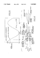
- FIG. 5 shows the transfer function of a Mach-Zender interferometer, used as an attenuator.
- FIG. 6 is a schematic diagram showing an embodiment of the invention for independently steering multiple beams from a phased antenna array.
- phase shifter For clarity of understanding, the concept underlying the claimed invention will first be explained in reference to a single channel phase shifter, and then to phase shifters for linear and two dimensional antenna arrays.
- signals from two phase locked optical sources at frequencies f 1 and f 2 are launched into an optical waveguide 10 in a substrate 12 as orthogonal TE and TM waves.
- this technique employs a pair of single-frequency lasers, such as Nd:YAG lasers, that are phase locked with a frequency offset.
- Frequency offset is controlled using standard phase-lock loop circuitry well-known in the art.
- Lasers that can easily generate a difference frequency from near DC to greater than 100 GHz. are commercially available with over 100 mW of CW output power coupled into an optical fiber. This permits reasonable signal levels after losses due to coupling, splitting, and distribution to multiple phased-array elements are taken into account.
- optical sources such as for example, phase-locked diode-pumped solid-state (DPSS) lasers or semiconductor lasers.
- DPSS phase-locked diode-pumped solid-state
- the particular optical sources used in the invention can be chosen according to the requirements desired for a particular application taking into account such factors as, for example, cost, tunability, size, acceptable noise levels, line width, etc.
- DPSS lasers can thus be phase locked with relatively simple electronic circuitry. These lasers are commonly furnished with a piezoelectric transducer (PZT) incorporated into the laser cavity by the manufacturer for frequency tuning and phase-locking applications. An applied voltage causes an incremental change is the cavity length, which shifts the laser oscillation frequency. The transfer function closely approximates that of an ideal voltage-controlled oscillator.
- PZT piezoelectric transducer
- the TE and TM waves which have been launched into the waveguide 10 are differentially phase shifted (i.e., the signal with one polarization is phase shifted by a different amount than the signal with the other polarization) by applying a DC voltage to the electrodes 32, 34 straddling the waveguide 10.
- the magnitude of the differential phase shift ⁇ is proportional to the amplitude of the applied voltage, the length of the electrodes, and the difference in the electro-optic coefficients of the waveguide for the two polarization states.
- a polarizer 36 such as, for example, a polarizing beam splitter, with its polarization axis oriented at an angle with respect to the two polarization states of the signals, sums the components of the two optical beams in that polarization axis.
- a polarizer having its polarization axis at 45 degrees to the two orthogonal polarization states will give good results. But, the exact angle of this polarization axis is not crucial and can be chosen as desired for a particular application, as long as the output from the polarizer includes components from both of the polarized signals.
- the light output from the polarizer 36 is sent through optical fiber to a photodiode 38 in a phased-array antenna module.
- a highly preferred material for the substrate 12 on which the integrated electro-optic circuit is fabricated is lithium niobate (LiNbO 3 ).
- LiNbO 3 lithium niobate
- High-quality waveguides can be easily formed in this material by titanium diffusion.
- LiNbO 3 has several other important attributes for this applications. Its large electro-optic coefficient allows for very efficient phase shifting over a full 2 ⁇ range with low applied voltage (less than 10 V). Substrates in sizes that allow complex, multi-stage optical circuits to be fabricated monolithically are readily available.
- the basic phase shifting technique discussed above can be used to form a multi-channel integrated electro-optic phase control circuit for steering a linear array.
- a 4-channel version of such a module is illustrated in FIG. 3. Although four channels are shown for purposes of illustration, it will be readily understood that any desired number of channels can be provided.
- the first section of the circuit 40 contains an input waveguide 41 which propagates the incoming signals in the TE and TM modes to waveguides forming a 1 ⁇ 4 beam divider 42 to split the input optical beams among the four phase-shift channels.
- a first electrode stage 44 has four separate electrodes, one for each channel, that provide for individually adjusting or tuning the initial phase state for each channel to be at a desired value, such as, for example, the same for all channels.
- This tuning electrode stage 44 could be placed before or after the phase shift electrodes, or omitted, as desired.
- the second electrode stage 46 has four electrodes that are connected to a common control voltage.
- the differential phase for any channel i is ⁇ i and is proportional to the electrode length L i and the applied voltage V.
- a linear taper of the electrode lengths is used so that application of a single control voltage produces a differential phase shift that varies linearly between channels.
- polarizing optical fiber 48 is used as a polarizer, although it will be understood that in this and all other embodiments, a polarizing beam splitter or other polarizing element could likewise be used.
- the optical outputs from the four channels are conveyed by polarizing optical fiber 48 to four high-speed photodiodes 50.
- the polarizing fiber 48 has its polarization axis at an angle such as 45 degrees to the input polarization states to effectively force the two original signals at orthogonal polarizations to mix at the detectors 50.
- Coherent detection in these photodiodes 50 produces a microwave beat signal that is amplified and radiated by the antenna elements 52. Any phase shift in the optical domain maps one-for-one into the microwave domain.
- the microwave beat frequency in the various channels have the same linear phase shift between them as is imposed on the optical carriers.
- the phase gradient between the channels determines the pointing direction of the radiated beam.
- the polarizing fibers 48 sum the frequency-offset laser beams which exit the second electrode stage 46 in a common polarization state (such as 45 degrees to the orthogonal polarizations of the beams).
- a common polarization state such as 45 degrees to the orthogonal polarizations of the beams.
- An important feature of the illustrated embodiment is that as they travel through the beam-control substrate 40, the orthogonal laser beams share a short, common optical path. After exiting this substrate and traveling through the polarizing fibers 48, the beams have the same polarization state and the signals for each channel travel through a common fiber. Temperature fluctuations or vibrations thus have negligible effect on the beat signal stability.
- FIG. 4 shows an embodiment of the invention adapted for controlling the two-axis positioning of a beam from a two-dimensional phased array.
- a circuit suitable for control of a 4 ⁇ 4 square array with sixteen antenna elements is shown.
- the same basic beam control strategy can be adapted for other geometries and sizes.
- the frequency-offset TE and TM modes are launched into a single-mode, polarization-maintaining fiber 54.
- These co-propagating beams are split by a fiber coupler among four fibers 55 that are coupled to the four input channel waveguides 60 of the monolithic integrated electro-optic control circuit 62.
- these four waveguides are four electrodes 64 with a linear length taper that phase shifts signals in response to a commonly applied control voltage, produces elevation beam steering in concert among all the antenna columns (it will be understood that reference to rows and columns are interchangeable and not intended to limit the invention to a particular orientation).
- This stage is followed by a 1 ⁇ 4 split of each input channel, resulting in sixteen channels in four sets of four.
- Astride these sixteen channels 66 are four identical sets of four electrodes with a linear length taper within each set.
- a single control voltage is sent to all sixteen electrodes.
- These electrodes 68 produce beam steering in azimuth among the array rows.
- the circuit would preferably have N input waveguide channels that are then split into (N ⁇ M) waveguides, in N sets of M channels.
- N ⁇ M the orthogonality of the beam steering axes permits the effective addition of cumulative differential phase shifts.
- controlling only two voltages produces the desired two-dimensional beam steering.
- Final phase bias electrodes 70 remove any channel-to-channel phase errors or apply any non-linear phase shifts that may be desired with, individual electrodes controlling the phase of each channel.
- the resulting sixteen calibrated outputs of the illustrated embodiment then pass to an array 72 of sixteen attenuators 74.
- Each of these attenuators can be a Mach-Zender interferometer.
- FIG. 5 plots the transfer function for a Mach-Zender integrated optical interferometer. An applied voltage shifts the phase of the optical signal in one of the two arms of the interferometer. At an applied voltage V o , the optical output drops to T o .
- the applied voltage is near DC and serves only to adjust the optical output for apodization.
- the attenuators make adjustments to apodize the phased array antenna aperture for sidelobe suppression, if desired, and to compensate for signal imbalances caused by optical loss, electrode efficiency, or electronic gain variations.
- the two polarizations will be mixed in polarizing fibers 75 with their polarization axes placed at 45 degrees with respect to both input polarizations.
- a silicon substrate 76 with V grooves properly aligned and oriented to the end face of the fibers couples the signals into the fibers.
- the sixteen output fibers carry the frequency-offset, phase -shifted optical beams to the photodiodes that preferably are located at the antenna array. Because the two optical beams in a channel co-propagate through the entire optical path from the first 1 ⁇ 4 split onward to the photodiodes, any environmental factors introducing spurious, or time-varying, phase-shifts in a channel affect both optical signals the same. Therefore, the differential phase-shift remains as set by the control voltages independent of environmental effects.
- variable time delay device can be combined with the invention to provide broadband steering of the single beam.
- An example of a suitable variable time delay device is shown in the inventor's copending U.S. patent application, Ser. No. Aug. 08/290,201 filed Aug. 15, 1994 for "Programmable Signal Time Delay Device Using Electro-Optic and Passive Waveguide Circuits on Planar Substrates," which is incorporated herein by reference.
- phase-shift function removes the phase-shift function from the antenna modules, it makes possible an operating mode not otherwise possible in phased array operation: simultaneous formation of independent beams at different frequencies.
- Optical-domain phase shifting with the present invention allows two or more phase shifters to operate in parallel outside the antenna modules on signals of different frequency. These signals can then be optically combined prior to delivery to the antenna. This approach avoids phase shift anomalies that would otherwise result from attempting to set the phase at two frequencies with a single device.
- FIG. 6 shows an example of an architecture for controlling two transmit frequencies for a single array 78.
- This architecture could utilize, for example, two lasers operating in parallel phase lock loops which share a common reference laser, or any other arrangement which results in two pairs of mutually orthogonal optical signals.
- the pairs of orthogonally polarized light signals are input into two integrated optic phase shift circuits 87, 88 constructed as described above, which operate independently in parallel. These two phase shift circuits 87, 88 can be fabricated on a single substrate. Outputs from each phase shift circuit are transmitted to high-speed photodetectors.
- a pair of microwave beat signals, one originating from each beam controller circuit, is transmitted to each antenna element.
Abstract
Description
Claims (9)
Priority Applications (2)
| Application Number | Priority Date | Filing Date | Title |
|---|---|---|---|
| US08/322,897 US5543805A (en) | 1994-10-13 | 1994-10-13 | Phased array beam controller using integrated electro-optic circuits |
| US08/655,333 US5751248A (en) | 1994-10-13 | 1996-05-24 | Phased array beam controller using integrated electro-optic circuits |
Applications Claiming Priority (1)
| Application Number | Priority Date | Filing Date | Title |
|---|---|---|---|
| US08/322,897 US5543805A (en) | 1994-10-13 | 1994-10-13 | Phased array beam controller using integrated electro-optic circuits |
Related Child Applications (1)
| Application Number | Title | Priority Date | Filing Date |
|---|---|---|---|
| US08/655,333 Continuation-In-Part US5751248A (en) | 1994-10-13 | 1996-05-24 | Phased array beam controller using integrated electro-optic circuits |
Publications (1)
| Publication Number | Publication Date |
|---|---|
| US5543805A true US5543805A (en) | 1996-08-06 |
Family
ID=23256918
Family Applications (1)
| Application Number | Title | Priority Date | Filing Date |
|---|---|---|---|
| US08/322,897 Expired - Lifetime US5543805A (en) | 1994-10-13 | 1994-10-13 | Phased array beam controller using integrated electro-optic circuits |
Country Status (1)
| Country | Link |
|---|---|
| US (1) | US5543805A (en) |
Cited By (94)
| Publication number | Priority date | Publication date | Assignee | Title |
|---|---|---|---|---|
| US5677697A (en) * | 1996-02-28 | 1997-10-14 | Hughes Electronics | Millimeter wave arrays using Rotman lens and optical heterodyne |
| US5751248A (en) * | 1994-10-13 | 1998-05-12 | The Boeing Company | Phased array beam controller using integrated electro-optic circuits |
| US5933001A (en) * | 1994-09-26 | 1999-08-03 | The Boeing Company | Method for using a wideband, high linear dynamic range sensor |
| US6128421A (en) * | 1999-02-22 | 2000-10-03 | Roberts; Rodger Allen | Electro-optical phased array beam modulator |
| US6252557B1 (en) * | 1999-09-30 | 2001-06-26 | Lockheed Martin Corporation | Photonics sensor array for wideband reception and processing of electromagnetic signals |
| US20020128045A1 (en) * | 2001-01-19 | 2002-09-12 | Chang Donald C. D. | Stratospheric platforms communication system using adaptive antennas |
| US6529162B2 (en) * | 2001-05-17 | 2003-03-04 | Irwin L. Newberg | Phased array antenna system with virtual time delay beam steering |
| US6563966B1 (en) | 1999-03-04 | 2003-05-13 | Finisar Corporation, Inc. | Method, systems and apparatus for providing true time delayed signals using optical inputs |
| US6606056B2 (en) | 2001-11-19 | 2003-08-12 | The Boeing Company | Beam steering controller for a curved surface phased array antenna |
| US6621468B2 (en) * | 2000-09-22 | 2003-09-16 | Sarnoff Corporation | Low loss RF power distribution network |
| US6703974B2 (en) | 2002-03-20 | 2004-03-09 | The Boeing Company | Antenna system having active polarization correlation and associated method |
| US6760512B2 (en) * | 2001-06-08 | 2004-07-06 | Hrl Laboratories, Llc | Electro-optical programmable true-time delay generator |
| US20060008393A1 (en) * | 2004-07-06 | 2006-01-12 | Diesel & Combustion Technologies Llc | Pollutant reduction system with adjustable angle injector for injecting pollutant reduction substance |
| US20060109194A1 (en) * | 2003-08-08 | 2006-05-25 | Picard Thomas G | Electromagnetic interference protection for radomes |
| US20070035442A1 (en) * | 2005-08-11 | 2007-02-15 | Waveband Corporation | Beam-forming antenna with amplitude-controlled antenna elements |
| US7187949B2 (en) | 2001-01-19 | 2007-03-06 | The Directv Group, Inc. | Multiple basestation communication system having adaptive antennas |
| KR100703629B1 (en) | 2005-11-30 | 2007-04-06 | 광주과학기술원 | Optical differential phase shift keying de-modulator |
| US7724994B1 (en) | 2008-02-04 | 2010-05-25 | Hrl Laboratories, Llc | Digitally controlled optical tapped time delay modules and arrays |
| US7729572B1 (en) | 2008-07-08 | 2010-06-01 | Hrl Laboratories, Llc | Optical tapped time delay modules and arrays |
| US7898464B1 (en) * | 2006-04-11 | 2011-03-01 | Lockheed Martin Corporation | System and method for transmitting signals via photonic excitation of a transmitter array |
| US7921442B2 (en) | 2000-08-16 | 2011-04-05 | The Boeing Company | Method and apparatus for simultaneous live television and data services using single beam antennas |
| US20110140965A1 (en) * | 2005-08-11 | 2011-06-16 | Manasson Vladimir A | Beam-forming antenna with amplitude-controlled antenna elements |
| US8326282B2 (en) | 2007-09-24 | 2012-12-04 | Panasonic Avionics Corporation | System and method for receiving broadcast content on a mobile platform during travel |
| US8390922B1 (en) * | 2008-07-29 | 2013-03-05 | University Of Washington | Phase matching for difference frequency generation and nonlinear optical conversion for planar waveguides via vertical coupling |
| US8402268B2 (en) | 2009-06-11 | 2013-03-19 | Panasonic Avionics Corporation | System and method for providing security aboard a moving platform |
| US8504217B2 (en) | 2009-12-14 | 2013-08-06 | Panasonic Avionics Corporation | System and method for providing dynamic power management |
| US8509990B2 (en) | 2008-12-15 | 2013-08-13 | Panasonic Avionics Corporation | System and method for performing real-time data analysis |
| US8704960B2 (en) | 2010-04-27 | 2014-04-22 | Panasonic Avionics Corporation | Deployment system and method for user interface devices |
| US8798406B1 (en) | 2008-03-05 | 2014-08-05 | University Of Washington Through Its Center For Commercialization | All optical modulation and switching with patterned optically absorbing polymers |
| US20140231627A1 (en) * | 2011-09-22 | 2014-08-21 | Ntt Electronics Corporation | Opto-electronic integrated circuit, array antenna transmitter, array antenna receiver, and transmitter |
| US8818141B1 (en) | 2010-06-25 | 2014-08-26 | University Of Washington | Transmission line driven slot waveguide mach-zehnder interferometers |
| US8909003B1 (en) | 2009-01-16 | 2014-12-09 | University Of Washington Through Its Center For Commercialization | Low-noise and high bandwidth electric field sensing with silicon-polymer integrated photonics and low drive voltage modulator fiber-based antenna link |
| US20150180122A1 (en) * | 2013-12-24 | 2015-06-25 | The Boeing Company | Integral rf-optical phased array module |
| CN104797930A (en) * | 2012-09-19 | 2015-07-22 | 原子能和替代能源委员会 | Thermal flow sensor, gas sensor comprising at least one such sensor and pirani gauge comprising at least one such sensor |
| US9108733B2 (en) | 2010-09-10 | 2015-08-18 | Panasonic Avionics Corporation | Integrated user interface system and method |
| US20150295327A1 (en) * | 2012-12-03 | 2015-10-15 | Telefonaktiebolaget L M Ericsson (Publ) | Wireless communication node with 4tx/4rx triple band antenna arrangement |
| US9252986B2 (en) | 2014-04-04 | 2016-02-02 | Nxgen Partners Ip, Llc | System and method for communication using orbital angular momentum with multiple layer overlay modulation |
| US9267877B2 (en) | 2014-03-12 | 2016-02-23 | Nxgen Partners Ip, Llc | System and method for making concentration measurements within a sample material using orbital angular momentum |
| US9307297B2 (en) | 2013-03-15 | 2016-04-05 | Panasonic Avionics Corporation | System and method for providing multi-mode wireless data distribution |
| US20160161600A1 (en) * | 2013-08-19 | 2016-06-09 | Quanergy Systems, Inc. | Optical phased array lidar system and method of using same |
| US9413448B2 (en) * | 2014-08-08 | 2016-08-09 | Nxgen Partners Ip, Llc | Systems and methods for focusing beams with mode division multiplexing |
| US9500586B2 (en) | 2014-07-24 | 2016-11-22 | Nxgen Partners Ip, Llc | System and method using OAM spectroscopy leveraging fractional orbital angular momentum as signature to detect materials |
| US9537575B2 (en) | 2014-08-08 | 2017-01-03 | Nxgen Partners Ip, Llc | Modulation and multiple access technique using orbital angular momentum |
| US9575001B2 (en) | 2014-07-24 | 2017-02-21 | Nxgen Partners Ip, Llc | System and method for detection of materials using orbital angular momentum signatures |
| US9595766B2 (en) | 2015-06-19 | 2017-03-14 | Nxgen Partners Ip, Llc | Patch antenna array for transmission of hermite-gaussian and laguerre gaussian beams |
| KR101720434B1 (en) * | 2015-11-10 | 2017-03-28 | 한국과학기술원 | Photonic phased array antenna |
| US9662019B2 (en) | 2014-04-09 | 2017-05-30 | Nxgen Partners Ip, Llc | Orbital angular momentum and fluorescence-based microendoscope spectroscopy for cancer diagnosis |
| US9753351B2 (en) | 2014-06-30 | 2017-09-05 | Quanergy Systems, Inc. | Planar beam forming and steering optical phased array chip and method of using same |
| US9784724B2 (en) | 2014-07-24 | 2017-10-10 | Nxgen Partners Ip, Llc | System and method for early detection of alzheimers by detecting amyloid-beta using orbital angular momentum |
| US9869753B2 (en) | 2014-08-15 | 2018-01-16 | Quanergy Systems, Inc. | Three-dimensional-mapping two-dimensional-scanning lidar based on one-dimensional-steering optical phased arrays and method of using same |
| US9998763B2 (en) | 2015-03-31 | 2018-06-12 | Nxgen Partners Ip, Llc | Compression of signals, images and video for multimedia, communications and other applications |
| US9998187B2 (en) | 2014-10-13 | 2018-06-12 | Nxgen Partners Ip, Llc | System and method for combining MIMO and mode-division multiplexing |
| US10006859B2 (en) | 2014-07-24 | 2018-06-26 | Nxgen Partners Ip, Llc | System and method for multi-parameter spectroscopy |
| US10014948B2 (en) | 2014-04-04 | 2018-07-03 | Nxgen Partners Ip, Llc | Re-generation and re-transmission of millimeter waves for building penetration |
| US10033082B1 (en) * | 2015-08-05 | 2018-07-24 | Waymo Llc | PCB integrated waveguide terminations and load |
| US10073417B2 (en) | 2014-08-08 | 2018-09-11 | Nxgen Partners Ip, Llc | System and method for applying orthogonal limitations to light beams using microelectromechanical systems |
| US10084541B2 (en) | 2014-04-04 | 2018-09-25 | Nxgen Partners Ip, Llc | Shorter wavelength transmission of OAM beams in conventional single mode fiber |
| CN108693504A (en) * | 2017-06-09 | 2018-10-23 | 深圳市涵光半导体有限公司 | Phased-array laser transmitter unit and control method, laser radar |
| US10132928B2 (en) | 2013-05-09 | 2018-11-20 | Quanergy Systems, Inc. | Solid state optical phased array lidar and method of using same |
| US10148360B2 (en) | 2016-06-17 | 2018-12-04 | Nxgen Partners Ip, Llc | System and method for communication using prolate spheroidal wave functions |
| US10161870B2 (en) | 2015-10-05 | 2018-12-25 | Nxgen Partners Ip, Llc | System and method for multi-parameter spectroscopy |
| US10168501B2 (en) | 2016-05-27 | 2019-01-01 | Nxgen Partners Ip, Llc | System and method for transmissions using eliptical core fibers |
| CN109301435A (en) * | 2017-07-25 | 2019-02-01 | 上海汇珏网络通信设备有限公司 | Array antenna |
| US10209192B2 (en) | 2015-10-05 | 2019-02-19 | Nxgen Partners Ip, Llc | Spectroscopy with correlation matrices, ratios and glycation |
| US10261244B2 (en) | 2016-02-15 | 2019-04-16 | Nxgen Partners Ip, Llc | System and method for producing vortex fiber |
| US10326526B2 (en) | 2016-09-08 | 2019-06-18 | Nxgen Partners Ip, Llc | Method for muxing orthogonal modes using modal correlation matrices |
| KR20190070041A (en) * | 2017-12-12 | 2019-06-20 | 한국과학기술원 | Method and apparatus for determining applied voltage in optical phased array antenna |
| US10374710B2 (en) | 2014-04-04 | 2019-08-06 | Nxgen Partners Ip, Llc | Re-generation and re-transmission of millimeter waves for building penetration |
| US10439287B2 (en) | 2017-12-21 | 2019-10-08 | Nxgen Partners Ip, Llc | Full duplex using OAM |
| US10451902B2 (en) | 2014-08-08 | 2019-10-22 | Nxgen Partners Ip, Llc | Suppression of electron-hole recombination using orbital angular momentum semiconductor devices |
| US10491303B2 (en) | 2017-03-22 | 2019-11-26 | Nxgen Partners Ip, Llc | Re-generation and re-transmission of millimeter waves for building penetration using dongle transceivers |
| US10516486B2 (en) | 2014-08-08 | 2019-12-24 | Nxgen Partners Ip, Llc | Modulation and multiple access technique using orbital angular momentum |
| US20190391243A1 (en) * | 2017-03-01 | 2019-12-26 | Pointcloud Inc. | Modular three-dimensional optical sensing system |
| WO2020040854A3 (en) * | 2018-06-19 | 2020-04-02 | The Regents Of The University Of California | Beam-steering system based on a mems-actuated vertical-coupler array |
| US10613410B2 (en) * | 2016-10-14 | 2020-04-07 | Analog Photonics LLC | Large scale optical phased array |
| US10613201B2 (en) | 2014-10-20 | 2020-04-07 | Quanergy Systems, Inc. | Three-dimensional lidar sensor based on two-dimensional scanning of one-dimensional optical emitter and method of using same |
| US10641876B2 (en) | 2017-04-06 | 2020-05-05 | Quanergy Systems, Inc. | Apparatus and method for mitigating LiDAR interference through pulse coding and frequency shifting |
| CN111146588A (en) * | 2018-11-06 | 2020-05-12 | 艾尔康系统有限责任公司 | Phased array antenna |
| US20200183086A1 (en) * | 2018-12-06 | 2020-06-11 | Optical Engines, Inc. | Photonic antenna array with tapered fiber ends |
| US10708046B1 (en) | 2018-11-08 | 2020-07-07 | Nxgen Partners Ip, Llc | Quantum resistant blockchain with multi-dimensional quantum key distribution |
| US10726353B2 (en) | 2015-08-03 | 2020-07-28 | Nxgen Partners Ip, Llc | Quantum mechanical framework for interaction of OAM with matter and applications in solid states, biosciences and quantum computing |
| US20200259256A1 (en) * | 2017-09-28 | 2020-08-13 | Gwangju Institute Of Science And Technology | Optical phased array antenna and lidar including same |
| RU2745979C1 (en) * | 2020-06-16 | 2021-04-05 | Федеральное государственное бюджетное образовательное учреждение высшего образования «Московский государственный университет имени М.В.Ломоносова» (МГУ) | Error-resistant multichannel polarizing converter of electromagnetic signals |
| US10992053B2 (en) * | 2016-07-11 | 2021-04-27 | Waymo Llc | Radar antenna array with parasitic elements excited by surface waves |
| US11088755B2 (en) | 2017-03-22 | 2021-08-10 | Nxgen Partners Ip, Llc | Re-generation and re-transmission of millimeter waves using roof mounted CPE unit |
| US11152991B2 (en) | 2020-01-23 | 2021-10-19 | Nxgen Partners Ip, Llc | Hybrid digital-analog mmwave repeater/relay with full duplex |
| US11202335B2 (en) | 2019-02-22 | 2021-12-14 | Nxgen Partners Ip, Llc | Combined tunneling and network management system |
| US11245486B2 (en) | 2014-10-13 | 2022-02-08 | Nxgen Partners Ip, Llc | Application of orbital angular momentum to Fiber, FSO and RF |
| US11267590B2 (en) | 2019-06-27 | 2022-03-08 | Nxgen Partners Ip, Llc | Radar system and method for detecting and identifying targets using orbital angular momentum correlation matrix |
| WO2023048785A1 (en) * | 2021-09-21 | 2023-03-30 | X Development Llc | Optical tracking module chip for wireless optical communication terminal |
| WO2023048876A1 (en) * | 2021-09-21 | 2023-03-30 | X Development Llc | Integrated on-chip wireless optical communication terminal |
| WO2023048910A1 (en) * | 2021-09-21 | 2023-03-30 | X Development Llc | Optical phased array architecture for wavefront sensing |
| US11754683B2 (en) | 2021-05-10 | 2023-09-12 | nEYE Systems, Inc. | Pseudo monostatic LiDAR with two-dimensional silicon photonic mems switch array |
| US11888530B2 (en) | 2021-09-21 | 2024-01-30 | X Development Llc | Optical tracking module chip for wireless optical communication terminal |
Citations (16)
| Publication number | Priority date | Publication date | Assignee | Title |
|---|---|---|---|---|
| US3331651A (en) * | 1963-06-24 | 1967-07-18 | Rca Corp | Phased array light deflecting system |
| US3964819A (en) * | 1974-05-09 | 1976-06-22 | Siemens Aktiengesellschaft | Integrated optical modulator |
| US4360921A (en) * | 1980-09-17 | 1982-11-23 | Xerox Corporation | Monolithic laser scanning device |
| US4396246A (en) * | 1980-10-02 | 1983-08-02 | Xerox Corporation | Integrated electro-optic wave guide modulator |
| US4607916A (en) * | 1984-03-19 | 1986-08-26 | Gte Laboratories Incorporated | Apparatus for controlling the rotation of the plane of linear polarization of linearly polarized radiant energy traversing an element of chromium chalcogenide spinel magnetic semiconductor with elliptically polarized radiant energy |
| US4739334A (en) * | 1986-09-30 | 1988-04-19 | The United States Of America As Represented By The Secretary Of The Air Force | Electro-optical beamforming network for phased array antennas |
| US4764738A (en) * | 1987-03-26 | 1988-08-16 | D. L. Fried Associates, Inc. | Agile beam control of optical phased array |
| US4767170A (en) * | 1985-11-20 | 1988-08-30 | Brother Kogyo Kabushiki Kaisha | Optical deflector device |
| US4814773A (en) * | 1983-05-11 | 1989-03-21 | Hughes Aircraft Company | Fiber optic feed network for radar |
| US4856094A (en) * | 1986-09-18 | 1989-08-08 | Siemens Aktiengesellschaft | Arrangement for polarization control, such as for an optical heterodyne or homodyne receiver |
| US4878724A (en) * | 1987-07-30 | 1989-11-07 | Trw Inc. | Electrooptically tunable phase-locked laser array |
| US4885589A (en) * | 1988-09-14 | 1989-12-05 | General Electric Company | Optical distribution of transmitter signals and antenna returns in a phased array radar system |
| JPH0336529A (en) * | 1989-07-03 | 1991-02-18 | Sharp Corp | Optical deflecting device |
| US5111517A (en) * | 1990-02-14 | 1992-05-05 | France Telecom Etablissment Autonome De Droit Public (Centre National D'etudes Des Telecommunications | Polarization beam splitter for guided light |
| US5333000A (en) * | 1992-04-03 | 1994-07-26 | The United States Of America As Represented By The United States Department Of Energy | Coherent optical monolithic phased-array antenna steering system |
| US5367305A (en) * | 1991-03-20 | 1994-11-22 | Dornier Gmbh | Method and apparatus for controlling an active antenna |
-
1994
- 1994-10-13 US US08/322,897 patent/US5543805A/en not_active Expired - Lifetime
Patent Citations (16)
| Publication number | Priority date | Publication date | Assignee | Title |
|---|---|---|---|---|
| US3331651A (en) * | 1963-06-24 | 1967-07-18 | Rca Corp | Phased array light deflecting system |
| US3964819A (en) * | 1974-05-09 | 1976-06-22 | Siemens Aktiengesellschaft | Integrated optical modulator |
| US4360921A (en) * | 1980-09-17 | 1982-11-23 | Xerox Corporation | Monolithic laser scanning device |
| US4396246A (en) * | 1980-10-02 | 1983-08-02 | Xerox Corporation | Integrated electro-optic wave guide modulator |
| US4814773A (en) * | 1983-05-11 | 1989-03-21 | Hughes Aircraft Company | Fiber optic feed network for radar |
| US4607916A (en) * | 1984-03-19 | 1986-08-26 | Gte Laboratories Incorporated | Apparatus for controlling the rotation of the plane of linear polarization of linearly polarized radiant energy traversing an element of chromium chalcogenide spinel magnetic semiconductor with elliptically polarized radiant energy |
| US4767170A (en) * | 1985-11-20 | 1988-08-30 | Brother Kogyo Kabushiki Kaisha | Optical deflector device |
| US4856094A (en) * | 1986-09-18 | 1989-08-08 | Siemens Aktiengesellschaft | Arrangement for polarization control, such as for an optical heterodyne or homodyne receiver |
| US4739334A (en) * | 1986-09-30 | 1988-04-19 | The United States Of America As Represented By The Secretary Of The Air Force | Electro-optical beamforming network for phased array antennas |
| US4764738A (en) * | 1987-03-26 | 1988-08-16 | D. L. Fried Associates, Inc. | Agile beam control of optical phased array |
| US4878724A (en) * | 1987-07-30 | 1989-11-07 | Trw Inc. | Electrooptically tunable phase-locked laser array |
| US4885589A (en) * | 1988-09-14 | 1989-12-05 | General Electric Company | Optical distribution of transmitter signals and antenna returns in a phased array radar system |
| JPH0336529A (en) * | 1989-07-03 | 1991-02-18 | Sharp Corp | Optical deflecting device |
| US5111517A (en) * | 1990-02-14 | 1992-05-05 | France Telecom Etablissment Autonome De Droit Public (Centre National D'etudes Des Telecommunications | Polarization beam splitter for guided light |
| US5367305A (en) * | 1991-03-20 | 1994-11-22 | Dornier Gmbh | Method and apparatus for controlling an active antenna |
| US5333000A (en) * | 1992-04-03 | 1994-07-26 | The United States Of America As Represented By The United States Department Of Energy | Coherent optical monolithic phased-array antenna steering system |
Non-Patent Citations (2)
| Title |
|---|
| V. Ramaswamy, M. D. Divino, R. D. Standley, Balanced Bridge Modulator Switch Using Ti diffused LiNbO 3 Strip Waveguides , Appl. Phys. Lett. 32(10), 15 May 1978. * |
| V. Ramaswamy, M. D. Divino, R. D. Standley, Balanced Bridge Modulator Switch Using Ti-diffused LiNbO3 Strip Waveguides, Appl. Phys. Lett. 32(10), 15 May 1978. |
Cited By (167)
| Publication number | Priority date | Publication date | Assignee | Title |
|---|---|---|---|---|
| US5933001A (en) * | 1994-09-26 | 1999-08-03 | The Boeing Company | Method for using a wideband, high linear dynamic range sensor |
| US5751248A (en) * | 1994-10-13 | 1998-05-12 | The Boeing Company | Phased array beam controller using integrated electro-optic circuits |
| US5677697A (en) * | 1996-02-28 | 1997-10-14 | Hughes Electronics | Millimeter wave arrays using Rotman lens and optical heterodyne |
| US6128421A (en) * | 1999-02-22 | 2000-10-03 | Roberts; Rodger Allen | Electro-optical phased array beam modulator |
| US6563966B1 (en) | 1999-03-04 | 2003-05-13 | Finisar Corporation, Inc. | Method, systems and apparatus for providing true time delayed signals using optical inputs |
| US6252557B1 (en) * | 1999-09-30 | 2001-06-26 | Lockheed Martin Corporation | Photonics sensor array for wideband reception and processing of electromagnetic signals |
| US7921442B2 (en) | 2000-08-16 | 2011-04-05 | The Boeing Company | Method and apparatus for simultaneous live television and data services using single beam antennas |
| US6621468B2 (en) * | 2000-09-22 | 2003-09-16 | Sarnoff Corporation | Low loss RF power distribution network |
| US7809403B2 (en) * | 2001-01-19 | 2010-10-05 | The Directv Group, Inc. | Stratospheric platforms communication system using adaptive antennas |
| US20020128045A1 (en) * | 2001-01-19 | 2002-09-12 | Chang Donald C. D. | Stratospheric platforms communication system using adaptive antennas |
| US7929984B2 (en) | 2001-01-19 | 2011-04-19 | The Directv Group, Inc. | Multiple basestation communication system having adaptive antennas |
| US7187949B2 (en) | 2001-01-19 | 2007-03-06 | The Directv Group, Inc. | Multiple basestation communication system having adaptive antennas |
| US6529162B2 (en) * | 2001-05-17 | 2003-03-04 | Irwin L. Newberg | Phased array antenna system with virtual time delay beam steering |
| US6760512B2 (en) * | 2001-06-08 | 2004-07-06 | Hrl Laboratories, Llc | Electro-optical programmable true-time delay generator |
| US6606056B2 (en) | 2001-11-19 | 2003-08-12 | The Boeing Company | Beam steering controller for a curved surface phased array antenna |
| US6703974B2 (en) | 2002-03-20 | 2004-03-09 | The Boeing Company | Antenna system having active polarization correlation and associated method |
| US20070024523A1 (en) * | 2003-08-08 | 2007-02-01 | Lockheed Martin Corporation | Electromagnetic Interference Protection for Radomes |
| US7161552B2 (en) * | 2003-08-08 | 2007-01-09 | Lockheed Martin Corporation | Electromagnetic interference protection for radomes |
| WO2005018050A3 (en) * | 2003-08-08 | 2006-05-26 | Lockheed Corp | Electromagnetic interference protection for radomes |
| US20060109194A1 (en) * | 2003-08-08 | 2006-05-25 | Picard Thomas G | Electromagnetic interference protection for radomes |
| US7557769B2 (en) | 2003-08-08 | 2009-07-07 | Lockheed Martin Corporation | Electromagnetic interference protection for radomes |
| US20060008393A1 (en) * | 2004-07-06 | 2006-01-12 | Diesel & Combustion Technologies Llc | Pollutant reduction system with adjustable angle injector for injecting pollutant reduction substance |
| US7456787B2 (en) * | 2005-08-11 | 2008-11-25 | Sierra Nevada Corporation | Beam-forming antenna with amplitude-controlled antenna elements |
| US8456360B2 (en) | 2005-08-11 | 2013-06-04 | Sierra Nevada Corporation | Beam-forming antenna with amplitude-controlled antenna elements |
| US20090167606A1 (en) * | 2005-08-11 | 2009-07-02 | Manasson Vladimir A | Beam-forming antenna with amplitude-controlled antenna elements |
| US7864112B2 (en) | 2005-08-11 | 2011-01-04 | Sierra Nevada Corporation | Beam-forming antenna with amplitude-controlled antenna elements |
| US8976066B2 (en) | 2005-08-11 | 2015-03-10 | Sierra Nevada Corporation | Beam-forming antenna with amplitude-controlled antenna elements |
| US20110140965A1 (en) * | 2005-08-11 | 2011-06-16 | Manasson Vladimir A | Beam-forming antenna with amplitude-controlled antenna elements |
| US20070035442A1 (en) * | 2005-08-11 | 2007-02-15 | Waveband Corporation | Beam-forming antenna with amplitude-controlled antenna elements |
| KR100703629B1 (en) | 2005-11-30 | 2007-04-06 | 광주과학기술원 | Optical differential phase shift keying de-modulator |
| US7898464B1 (en) * | 2006-04-11 | 2011-03-01 | Lockheed Martin Corporation | System and method for transmitting signals via photonic excitation of a transmitter array |
| US9185433B2 (en) | 2007-09-24 | 2015-11-10 | Panasonic Avionics Corporation | System and method for receiving broadcast content on a mobile platform during travel |
| US8326282B2 (en) | 2007-09-24 | 2012-12-04 | Panasonic Avionics Corporation | System and method for receiving broadcast content on a mobile platform during travel |
| US7724994B1 (en) | 2008-02-04 | 2010-05-25 | Hrl Laboratories, Llc | Digitally controlled optical tapped time delay modules and arrays |
| US8798406B1 (en) | 2008-03-05 | 2014-08-05 | University Of Washington Through Its Center For Commercialization | All optical modulation and switching with patterned optically absorbing polymers |
| US7729572B1 (en) | 2008-07-08 | 2010-06-01 | Hrl Laboratories, Llc | Optical tapped time delay modules and arrays |
| US8390922B1 (en) * | 2008-07-29 | 2013-03-05 | University Of Washington | Phase matching for difference frequency generation and nonlinear optical conversion for planar waveguides via vertical coupling |
| US8509990B2 (en) | 2008-12-15 | 2013-08-13 | Panasonic Avionics Corporation | System and method for performing real-time data analysis |
| US8909003B1 (en) | 2009-01-16 | 2014-12-09 | University Of Washington Through Its Center For Commercialization | Low-noise and high bandwidth electric field sensing with silicon-polymer integrated photonics and low drive voltage modulator fiber-based antenna link |
| US8402268B2 (en) | 2009-06-11 | 2013-03-19 | Panasonic Avionics Corporation | System and method for providing security aboard a moving platform |
| US8504217B2 (en) | 2009-12-14 | 2013-08-06 | Panasonic Avionics Corporation | System and method for providing dynamic power management |
| US8897924B2 (en) | 2009-12-14 | 2014-11-25 | Panasonic Avionics Corporation | System and method for providing dynamic power management |
| US8704960B2 (en) | 2010-04-27 | 2014-04-22 | Panasonic Avionics Corporation | Deployment system and method for user interface devices |
| US8818141B1 (en) | 2010-06-25 | 2014-08-26 | University Of Washington | Transmission line driven slot waveguide mach-zehnder interferometers |
| US9108733B2 (en) | 2010-09-10 | 2015-08-18 | Panasonic Avionics Corporation | Integrated user interface system and method |
| US9857217B2 (en) * | 2011-09-22 | 2018-01-02 | Nippon Telegraph And Telephone Corporation | Opto-electronic integrated circuit, array antenna transmitter, array antenna receiver, and transmitter |
| US20140231627A1 (en) * | 2011-09-22 | 2014-08-21 | Ntt Electronics Corporation | Opto-electronic integrated circuit, array antenna transmitter, array antenna receiver, and transmitter |
| CN104797930A (en) * | 2012-09-19 | 2015-07-22 | 原子能和替代能源委员会 | Thermal flow sensor, gas sensor comprising at least one such sensor and pirani gauge comprising at least one such sensor |
| US20150247828A1 (en) * | 2012-09-19 | 2015-09-03 | Commissariat A L'energie Atomique Et Aux Energies Alternatives | Thermal flow sensor, gas sensor comprising at least one such sensor and pirani gauge comprising at least one such sensor |
| US9709536B2 (en) * | 2012-09-19 | 2017-07-18 | Commissariat à l'énergie atomique et aux énergies alternatives | Thermal flow sensor, gas sensor comprising at least one such sensor and Pirani gauge comprising at least one such sensor |
| US20150295327A1 (en) * | 2012-12-03 | 2015-10-15 | Telefonaktiebolaget L M Ericsson (Publ) | Wireless communication node with 4tx/4rx triple band antenna arrangement |
| US9774098B2 (en) * | 2012-12-03 | 2017-09-26 | Telefonaktiebolaget Lm Ericsson (Publ) | Wireless communication node with 4TX/4RX triple band antenna arrangement |
| US9307297B2 (en) | 2013-03-15 | 2016-04-05 | Panasonic Avionics Corporation | System and method for providing multi-mode wireless data distribution |
| US11209546B1 (en) | 2013-05-09 | 2021-12-28 | Quanergy Systems, Inc. | Solid state optical phased array lidar and method of using same |
| US10132928B2 (en) | 2013-05-09 | 2018-11-20 | Quanergy Systems, Inc. | Solid state optical phased array lidar and method of using same |
| US20160161600A1 (en) * | 2013-08-19 | 2016-06-09 | Quanergy Systems, Inc. | Optical phased array lidar system and method of using same |
| US10126412B2 (en) * | 2013-08-19 | 2018-11-13 | Quanergy Systems, Inc. | Optical phased array lidar system and method of using same |
| US20150180122A1 (en) * | 2013-12-24 | 2015-06-25 | The Boeing Company | Integral rf-optical phased array module |
| US9595757B2 (en) * | 2013-12-24 | 2017-03-14 | The Boeing Company | Integral RF-optical phased array module |
| US10197554B2 (en) | 2014-03-12 | 2019-02-05 | NxGen Partners IP, LLP | System and method for early detection of Alzheimers by detecting amyloid-beta using orbital angular momentum |
| US10132750B2 (en) | 2014-03-12 | 2018-11-20 | Nxgen Partners Ip, Llc | System and method using OAM spectroscopy leveraging fractional orbital angular momentum as signature to detect materials |
| US9267877B2 (en) | 2014-03-12 | 2016-02-23 | Nxgen Partners Ip, Llc | System and method for making concentration measurements within a sample material using orbital angular momentum |
| US9714902B2 (en) | 2014-03-12 | 2017-07-25 | Nxgen Partners Ip, Llc | System and method for making concentration measurements within a sample material using orbital angular momentum |
| US10082463B2 (en) | 2014-03-12 | 2018-09-25 | Nxgen Partners Ip, Llc | System and method for making concentration measurements within a sample material using orbital angular momentum |
| US9331875B2 (en) | 2014-04-04 | 2016-05-03 | Nxgen Partners Ip, Llc | System and method for communication using orbital angular momentum with multiple layer overlay modulation |
| US10887013B2 (en) | 2014-04-04 | 2021-01-05 | Nxgen Partners Ip, Llc | System and method for communication using orbital angular momentum with multiple layer overlay modulation |
| US10014948B2 (en) | 2014-04-04 | 2018-07-03 | Nxgen Partners Ip, Llc | Re-generation and re-transmission of millimeter waves for building penetration |
| US10411804B2 (en) | 2014-04-04 | 2019-09-10 | Nxgen Partners Ip, Llc | System and method for communicating using orbital angular momentum with multiple layer overlay modulation |
| US9712238B2 (en) | 2014-04-04 | 2017-07-18 | Nxgen Partners Ip, Llc | System and method for communication using orbital angular momentum with multiple layer overlay modulation |
| US10778332B2 (en) | 2014-04-04 | 2020-09-15 | Nxgen Partners Ip, Llc | Patch antenna for wave agility |
| US9252986B2 (en) | 2014-04-04 | 2016-02-02 | Nxgen Partners Ip, Llc | System and method for communication using orbital angular momentum with multiple layer overlay modulation |
| US10784962B2 (en) | 2014-04-04 | 2020-09-22 | Nxgen Partners Ip, Llc | System for millimeter wave building penetration using beam forming and beam steering |
| US10153845B2 (en) | 2014-04-04 | 2018-12-11 | Nxgen Partners Ip, Llc | Re-generation and re-transmission of millimeter waves for building penetration |
| US10374710B2 (en) | 2014-04-04 | 2019-08-06 | Nxgen Partners Ip, Llc | Re-generation and re-transmission of millimeter waves for building penetration |
| US9503258B2 (en) | 2014-04-04 | 2016-11-22 | Nxgen Partners Ip, Llc | System and method for communication using orbital angular momentum with multiple layer overlay modulation |
| US11283522B2 (en) | 2014-04-04 | 2022-03-22 | Nxgen Partners Ip, Llc | System and method for powering re-generation and re-transmission of millimeter waves for building penetration |
| US9859981B2 (en) | 2014-04-04 | 2018-01-02 | Nxgen Partners Ip, Llc | System and method for communication using orbital angular momentum with multiple layer overlay modulation |
| US11901943B2 (en) | 2014-04-04 | 2024-02-13 | Nxgen Partners Ip, Llc | System and method for powering re-generation and re-transmission of millimeter waves for building penetration |
| US10084541B2 (en) | 2014-04-04 | 2018-09-25 | Nxgen Partners Ip, Llc | Shorter wavelength transmission of OAM beams in conventional single mode fiber |
| US10105058B2 (en) | 2014-04-09 | 2018-10-23 | Nxgen Partners Ip, Llc | Orbital angular momentum and fluorescence- based microendoscope spectroscopy for cancer diagnosis |
| US9662019B2 (en) | 2014-04-09 | 2017-05-30 | Nxgen Partners Ip, Llc | Orbital angular momentum and fluorescence-based microendoscope spectroscopy for cancer diagnosis |
| US9964833B2 (en) | 2014-06-30 | 2018-05-08 | Quanergy Systems, Inc. | Planar beam forming and steering optical phased array chip and method of using same |
| US9753351B2 (en) | 2014-06-30 | 2017-09-05 | Quanergy Systems, Inc. | Planar beam forming and steering optical phased array chip and method of using same |
| US10006859B2 (en) | 2014-07-24 | 2018-06-26 | Nxgen Partners Ip, Llc | System and method for multi-parameter spectroscopy |
| US9645083B2 (en) | 2014-07-24 | 2017-05-09 | Nxgen Partners Ip, Llc | System and method using OAM spectroscopy leveraging fractional orbital angular momentum as signature to detect materials |
| US9784724B2 (en) | 2014-07-24 | 2017-10-10 | Nxgen Partners Ip, Llc | System and method for early detection of alzheimers by detecting amyloid-beta using orbital angular momentum |
| US10048202B2 (en) | 2014-07-24 | 2018-08-14 | Nxgen Partners Ip, Llc | System and method for detection of materials using orbital angular momentum signatures |
| US9575001B2 (en) | 2014-07-24 | 2017-02-21 | Nxgen Partners Ip, Llc | System and method for detection of materials using orbital angular momentum signatures |
| US9810628B2 (en) | 2014-07-24 | 2017-11-07 | Nxgen Partners Ip, Llc | System and method for detection of materials using orbital angular momentum signatures |
| US9500586B2 (en) | 2014-07-24 | 2016-11-22 | Nxgen Partners Ip, Llc | System and method using OAM spectroscopy leveraging fractional orbital angular momentum as signature to detect materials |
| US9413448B2 (en) * | 2014-08-08 | 2016-08-09 | Nxgen Partners Ip, Llc | Systems and methods for focusing beams with mode division multiplexing |
| US20160359539A1 (en) * | 2014-08-08 | 2016-12-08 | Nxgen Partners Ip, Llc | Systems and methods for focusing beams with mode division multiplexing |
| US9537575B2 (en) | 2014-08-08 | 2017-01-03 | Nxgen Partners Ip, Llc | Modulation and multiple access technique using orbital angular momentum |
| US10707945B2 (en) | 2014-08-08 | 2020-07-07 | Nxgen Partners Ip, Llc | Systems and methods for focusing beams with mode division multiplexing |
| US10451902B2 (en) | 2014-08-08 | 2019-10-22 | Nxgen Partners Ip, Llc | Suppression of electron-hole recombination using orbital angular momentum semiconductor devices |
| US10073417B2 (en) | 2014-08-08 | 2018-09-11 | Nxgen Partners Ip, Llc | System and method for applying orthogonal limitations to light beams using microelectromechanical systems |
| US10193611B2 (en) * | 2014-08-08 | 2019-01-29 | Nxgen Ip Partners, Llc | Systems and methods for focusing beams with mode division multiplexing |
| US10516486B2 (en) | 2014-08-08 | 2019-12-24 | Nxgen Partners Ip, Llc | Modulation and multiple access technique using orbital angular momentum |
| US10921753B2 (en) | 2014-08-08 | 2021-02-16 | Nxgen Partners Ip, Llc | System and method for applying orthogonal limitations to light beams using microelectromechanical systems |
| US10180493B2 (en) | 2014-08-15 | 2019-01-15 | Quanergy Systems, Inc. | Three-dimensional-mapping two-dimensional-scanning LIDAR based on one-dimensional-steering optical phased arrays and method of using same |
| US9869753B2 (en) | 2014-08-15 | 2018-01-16 | Quanergy Systems, Inc. | Three-dimensional-mapping two-dimensional-scanning lidar based on one-dimensional-steering optical phased arrays and method of using same |
| US9816923B2 (en) | 2014-09-03 | 2017-11-14 | Nxgen Partners Ip, Llc | System and method using OAM spectroscopy leveraging fractional orbital angular momentum as signature to detect materials |
| US10530435B2 (en) | 2014-10-13 | 2020-01-07 | Nxgen Partners Ip, Llc | System and method for combining MIMO and mode-division multiplexing |
| US11245486B2 (en) | 2014-10-13 | 2022-02-08 | Nxgen Partners Ip, Llc | Application of orbital angular momentum to Fiber, FSO and RF |
| US11362706B2 (en) | 2014-10-13 | 2022-06-14 | Nxgen Partners Ip, Llc | System and method for combining MIMO and mode-division multiplexing |
| US9998187B2 (en) | 2014-10-13 | 2018-06-12 | Nxgen Partners Ip, Llc | System and method for combining MIMO and mode-division multiplexing |
| US10613201B2 (en) | 2014-10-20 | 2020-04-07 | Quanergy Systems, Inc. | Three-dimensional lidar sensor based on two-dimensional scanning of one-dimensional optical emitter and method of using same |
| US9998763B2 (en) | 2015-03-31 | 2018-06-12 | Nxgen Partners Ip, Llc | Compression of signals, images and video for multimedia, communications and other applications |
| US9793615B2 (en) | 2015-06-19 | 2017-10-17 | Nxgen Partners Ip, Llc | Patch antenna array for transmission of Hermite-Gaussian and Laguerre Gaussian beams |
| US9595766B2 (en) | 2015-06-19 | 2017-03-14 | Nxgen Partners Ip, Llc | Patch antenna array for transmission of hermite-gaussian and laguerre gaussian beams |
| US10608768B2 (en) | 2015-06-19 | 2020-03-31 | Nxgen Partners Ip, Llc | Patch antenna array for transmission of hermite-gaussian and laguerre gaussian beams |
| US10027434B2 (en) | 2015-06-19 | 2018-07-17 | Nxgen Partners Ip, Llc | Patch antenna array for transmission of hermite-gaussian and laguerre gaussian beams |
| US10726353B2 (en) | 2015-08-03 | 2020-07-28 | Nxgen Partners Ip, Llc | Quantum mechanical framework for interaction of OAM with matter and applications in solid states, biosciences and quantum computing |
| US11164104B2 (en) | 2015-08-03 | 2021-11-02 | Nxgen Partners Ip, Llc | Quantum mechanical framework for interaction of OAM with matter and applications in solid states, biosciences and quantum computing |
| US20180323488A1 (en) * | 2015-08-05 | 2018-11-08 | Waymo Llc | PCB Integrated Waveguide Terminations and Load |
| US10498002B2 (en) * | 2015-08-05 | 2019-12-03 | Waymo Llc | PCB integrated waveguide terminations and load |
| US10033082B1 (en) * | 2015-08-05 | 2018-07-24 | Waymo Llc | PCB integrated waveguide terminations and load |
| US20200067167A1 (en) * | 2015-08-05 | 2020-02-27 | Waymo Llc | PCB Integrated Waveguide Terminations and Load |
| US10938083B2 (en) * | 2015-08-05 | 2021-03-02 | Waymo Llc | PCB integrated waveguide terminations and load |
| US10161870B2 (en) | 2015-10-05 | 2018-12-25 | Nxgen Partners Ip, Llc | System and method for multi-parameter spectroscopy |
| US11002677B2 (en) | 2015-10-05 | 2021-05-11 | Nxgen Partners Ip, Llc | System and method for multi-parameter spectroscopy |
| US10209192B2 (en) | 2015-10-05 | 2019-02-19 | Nxgen Partners Ip, Llc | Spectroscopy with correlation matrices, ratios and glycation |
| US10444148B2 (en) | 2015-10-05 | 2019-10-15 | Nxgen Partners Ip, Llc | System and method for multi-parameter spectroscopy |
| KR101720434B1 (en) * | 2015-11-10 | 2017-03-28 | 한국과학기술원 | Photonic phased array antenna |
| WO2017082440A1 (en) * | 2015-11-10 | 2017-05-18 | 한국과학기술원 | Optical phased array antenna |
| US10261244B2 (en) | 2016-02-15 | 2019-04-16 | Nxgen Partners Ip, Llc | System and method for producing vortex fiber |
| US11249247B2 (en) | 2016-02-15 | 2022-02-15 | Nxgen Partners Ip, Llc | Preform for producing vortex fiber |
| US10168501B2 (en) | 2016-05-27 | 2019-01-01 | Nxgen Partners Ip, Llc | System and method for transmissions using eliptical core fibers |
| US10148360B2 (en) | 2016-06-17 | 2018-12-04 | Nxgen Partners Ip, Llc | System and method for communication using prolate spheroidal wave functions |
| US10992053B2 (en) * | 2016-07-11 | 2021-04-27 | Waymo Llc | Radar antenna array with parasitic elements excited by surface waves |
| US10326526B2 (en) | 2016-09-08 | 2019-06-18 | Nxgen Partners Ip, Llc | Method for muxing orthogonal modes using modal correlation matrices |
| US10613410B2 (en) * | 2016-10-14 | 2020-04-07 | Analog Photonics LLC | Large scale optical phased array |
| US20190391243A1 (en) * | 2017-03-01 | 2019-12-26 | Pointcloud Inc. | Modular three-dimensional optical sensing system |
| US11585899B2 (en) * | 2017-03-01 | 2023-02-21 | Pointcloud Inc. | Modular three-dimensional optical sensing system |
| US11088755B2 (en) | 2017-03-22 | 2021-08-10 | Nxgen Partners Ip, Llc | Re-generation and re-transmission of millimeter waves using roof mounted CPE unit |
| US10491303B2 (en) | 2017-03-22 | 2019-11-26 | Nxgen Partners Ip, Llc | Re-generation and re-transmission of millimeter waves for building penetration using dongle transceivers |
| US10903906B2 (en) | 2017-03-22 | 2021-01-26 | Nxgen Partners Ip, Llc | Re-generation and re-transmission of millimeter waves for building penetration using dongle transceivers |
| US10641876B2 (en) | 2017-04-06 | 2020-05-05 | Quanergy Systems, Inc. | Apparatus and method for mitigating LiDAR interference through pulse coding and frequency shifting |
| CN108693504A (en) * | 2017-06-09 | 2018-10-23 | 深圳市涵光半导体有限公司 | Phased-array laser transmitter unit and control method, laser radar |
| CN109301435A (en) * | 2017-07-25 | 2019-02-01 | 上海汇珏网络通信设备有限公司 | Array antenna |
| US20200259256A1 (en) * | 2017-09-28 | 2020-08-13 | Gwangju Institute Of Science And Technology | Optical phased array antenna and lidar including same |
| US11575199B2 (en) * | 2017-09-28 | 2023-02-07 | Gwangju Institute Of Science And Technology | Optical phased array antenna and LiDAR including same |
| KR102010409B1 (en) | 2017-12-12 | 2019-10-21 | 한국과학기술원 | Method and apparatus for determining applied voltage in optical phased array antenna |
| KR20190070041A (en) * | 2017-12-12 | 2019-06-20 | 한국과학기술원 | Method and apparatus for determining applied voltage in optical phased array antenna |
| US10439287B2 (en) | 2017-12-21 | 2019-10-08 | Nxgen Partners Ip, Llc | Full duplex using OAM |
| US11081796B2 (en) | 2017-12-21 | 2021-08-03 | Nxgen Partners Ip, Llc | Full duplex using OAM |
| CN112740063A (en) * | 2018-06-19 | 2021-04-30 | 加利福尼亚大学董事会 | Beam steering system based on MEMS actuated vertical coupler array |
| US11781379B2 (en) | 2018-06-19 | 2023-10-10 | The Regents Of The University Of California | Beam-steering system based on a MEMS-actuated vertical-coupler array |
| US11441353B2 (en) | 2018-06-19 | 2022-09-13 | The Regents Of The University Of California | Beam-steering system based on a MEMS-actuated vertical-coupler array |
| WO2020040854A3 (en) * | 2018-06-19 | 2020-04-02 | The Regents Of The University Of California | Beam-steering system based on a mems-actuated vertical-coupler array |
| CN111146588A (en) * | 2018-11-06 | 2020-05-12 | 艾尔康系统有限责任公司 | Phased array antenna |
| CN111146588B (en) * | 2018-11-06 | 2022-04-29 | 艾尔康系统有限责任公司 | Phased array antenna |
| US11621836B2 (en) | 2018-11-08 | 2023-04-04 | Nxgen Partners Ip, Llc | Quantum resistant blockchain with multi-dimensional quantum key distribution |
| US10708046B1 (en) | 2018-11-08 | 2020-07-07 | Nxgen Partners Ip, Llc | Quantum resistant blockchain with multi-dimensional quantum key distribution |
| US11579366B2 (en) * | 2018-12-06 | 2023-02-14 | Optical Engines, Inc. | Photonic antenna array with tapered fiber ends |
| US20200183086A1 (en) * | 2018-12-06 | 2020-06-11 | Optical Engines, Inc. | Photonic antenna array with tapered fiber ends |
| US11202335B2 (en) | 2019-02-22 | 2021-12-14 | Nxgen Partners Ip, Llc | Combined tunneling and network management system |
| US11267590B2 (en) | 2019-06-27 | 2022-03-08 | Nxgen Partners Ip, Llc | Radar system and method for detecting and identifying targets using orbital angular momentum correlation matrix |
| US11489573B2 (en) | 2020-01-23 | 2022-11-01 | Nxgen Partners Ip, Llc | Hybrid digital-analog mmwave repeater/relay with full duplex |
| US11791877B1 (en) | 2020-01-23 | 2023-10-17 | Nxgen Partners Ip, Llc | Hybrid digital-analog MMWAVE repeater/relay with full duplex |
| US11152991B2 (en) | 2020-01-23 | 2021-10-19 | Nxgen Partners Ip, Llc | Hybrid digital-analog mmwave repeater/relay with full duplex |
| RU2745979C1 (en) * | 2020-06-16 | 2021-04-05 | Федеральное государственное бюджетное образовательное учреждение высшего образования «Московский государственный университет имени М.В.Ломоносова» (МГУ) | Error-resistant multichannel polarizing converter of electromagnetic signals |
| US11754683B2 (en) | 2021-05-10 | 2023-09-12 | nEYE Systems, Inc. | Pseudo monostatic LiDAR with two-dimensional silicon photonic mems switch array |
| WO2023048785A1 (en) * | 2021-09-21 | 2023-03-30 | X Development Llc | Optical tracking module chip for wireless optical communication terminal |
| WO2023048876A1 (en) * | 2021-09-21 | 2023-03-30 | X Development Llc | Integrated on-chip wireless optical communication terminal |
| WO2023048910A1 (en) * | 2021-09-21 | 2023-03-30 | X Development Llc | Optical phased array architecture for wavefront sensing |
| US11888530B2 (en) | 2021-09-21 | 2024-01-30 | X Development Llc | Optical tracking module chip for wireless optical communication terminal |
Similar Documents
| Publication | Publication Date | Title |
|---|---|---|
| US5543805A (en) | Phased array beam controller using integrated electro-optic circuits | |
| US5751248A (en) | Phased array beam controller using integrated electro-optic circuits | |
| US4739334A (en) | Electro-optical beamforming network for phased array antennas | |
| US9689968B2 (en) | Wholly optically controlled phased array radar transmitter | |
| USRE38809E1 (en) | Photonic variable delay devices based on optical birefringence | |
| US6337660B1 (en) | Fiber optic true time-delay array antenna feed system | |
| US5761351A (en) | Wavelength-addressable optical time-delay network and phased array antenna incorporating the same | |
| US4671605A (en) | Length dependent, optical time delay/filter device for electrical signals | |
| US6348890B1 (en) | Phased array antenna beamformer | |
| US8779977B2 (en) | Electro optical scanning phased array antenna for pulsed operation | |
| US20090067772A1 (en) | Microwave photonic delay line with separate tuning of optical carrier | |
| Cheng et al. | An integrated optical beamforming network for two-dimensional phased array radar | |
| Horikawa et al. | Photonic switched true time delay beam forming network integrated on silica waveguide circuits | |
| US11183770B2 (en) | Dual polarization RF antenna feed module and photonic integrated circuit (PIC) | |
| Seeds | Optical technologies for phased array antennas | |
| Horikawa et al. | Self-heterodyning optical waveguide beam forming and steering network integrated on Lithium Niobate substrate | |
| HORIKAWA et al. | Photonic integrated beam forming and steering network using switched true-time-delay silica-based waveguide circuits | |
| Jez et al. | Optical waveguide components for beam forming in phased‐array antennas | |
| JP2013070210A (en) | Photo mixer and optoelectronic integrated circuit | |
| Gallo et al. | Experimental demonstration of optical guided-wave butler matrices | |
| US5467414A (en) | Device for generating feedback signals to regulate optical monitoring circuits (PLL) | |
| Liu et al. | Millimeter wave beamsteering with true time delayed integrated optical beamforming network | |
| Serafino et al. | Photonic integrated circuits for beamforming in 5G wireless communications | |
| Madrid et al. | A novel 2N beams heterodyne optical beamforming architecture based on N/spl times/N optical Butler matrices | |
| Liu et al. | True Time Delay Millimeter Wave Beam Steering with Integrated Optical Beamforming Network |
Legal Events
| Date | Code | Title | Description |
|---|---|---|---|
| AS | Assignment |
Owner name: BOEING COMPANY, THE, WASHINGTON Free format text: ASSIGNMENT OF ASSIGNORS INTEREST;ASSIGNOR:THANIYAVARN, SUWAT;REEL/FRAME:007883/0633 Effective date: 19960405 |
|
| AS | Assignment |
Owner name: BOEING COMPANY, THE, WASHINGTON Free format text: ASSIGNMENT OF ASSIGNORS INTEREST;ASSIGNOR:THANIYAVARN, SUWAT;REEL/FRAME:008025/0768 Effective date: 19960521 |
|
| STCF | Information on status: patent grant |
Free format text: PATENTED CASE |
|
| FEPP | Fee payment procedure |
Free format text: PAYOR NUMBER ASSIGNED (ORIGINAL EVENT CODE: ASPN); ENTITY STATUS OF PATENT OWNER: LARGE ENTITY |
|
| FPAY | Fee payment |
Year of fee payment: 4 |
|
| FPAY | Fee payment |
Year of fee payment: 8 |
|
| FPAY | Fee payment |
Year of fee payment: 12 |
|
| REMI | Maintenance fee reminder mailed |