US5549537A - Apparatus for the shaping treatment of blanks, especially for hinge-lid packs - Google Patents
Apparatus for the shaping treatment of blanks, especially for hinge-lid packs Download PDFInfo
- Publication number
- US5549537A US5549537A US08/386,627 US38662795A US5549537A US 5549537 A US5549537 A US 5549537A US 38662795 A US38662795 A US 38662795A US 5549537 A US5549537 A US 5549537A
- Authority
- US
- United States
- Prior art keywords
- shaping
- blank
- rollers
- plate
- blanks
- Prior art date
- Legal status (The legal status is an assumption and is not a legal conclusion. Google has not performed a legal analysis and makes no representation as to the accuracy of the status listed.)
- Expired - Lifetime
Links
Images


Classifications
-
- B—PERFORMING OPERATIONS; TRANSPORTING
- B31—MAKING ARTICLES OF PAPER, CARDBOARD OR MATERIAL WORKED IN A MANNER ANALOGOUS TO PAPER; WORKING PAPER, CARDBOARD OR MATERIAL WORKED IN A MANNER ANALOGOUS TO PAPER
- B31B—MAKING CONTAINERS OF PAPER, CARDBOARD OR MATERIAL WORKED IN A MANNER ANALOGOUS TO PAPER
- B31B50/00—Making rigid or semi-rigid containers, e.g. boxes or cartons
- B31B50/59—Shaping sheet material under pressure
-
- B—PERFORMING OPERATIONS; TRANSPORTING
- B31—MAKING ARTICLES OF PAPER, CARDBOARD OR MATERIAL WORKED IN A MANNER ANALOGOUS TO PAPER; WORKING PAPER, CARDBOARD OR MATERIAL WORKED IN A MANNER ANALOGOUS TO PAPER
- B31B—MAKING CONTAINERS OF PAPER, CARDBOARD OR MATERIAL WORKED IN A MANNER ANALOGOUS TO PAPER
- B31B50/00—Making rigid or semi-rigid containers, e.g. boxes or cartons
- B31B50/26—Folding sheets, blanks or webs
- B31B50/44—Folding sheets, blanks or webs by plungers moving through folding dies
Definitions
- the invention relates to an apparatus for shaping or pre-shaping blanks for packs, especially hinge-lid packs with rounded or polygonal longitudinal edges, wherein the blanks can be fed to a shaping station having at least one shaping device comprised of a shaping plate with shaping longitudinal margins and movable shaping tools, especially shaping rollers, the movable shaping tools being movable along marginal regions of the shaping plate, especially from the bottom side of the shaping plate to the top side, thereby deforming the blank.
- Hinge-lid packs are a widespread pack type for cigarettes. Recently, hinge-lid packs for cigarettes whose longitudinal edges have a rounded, beveled or polygonal design have been increasingly used. The production of such packs requires a preparatory treatment of the blanks, specifically a deformation of the same in the region of longitudinal edges.
- An example for an apparatus for shaping or pre-shaping blanks for hinge-lid packs is shown and described in U.S. Pat. No. 4,708,704 Focke et al (assigned to the assignee of the present application).
- the present invention relates to a development or improvement of the apparatus according to U.S. Pat. No. 4,708,704, or similar shaping apparatuses for blanks.
- the invention is based on the object to design an apparatus of the foregoing type in such a manner that a higher performance is attained when shaping or pre-shaping the blanks.
- the apparatus according to the invention is characterized in that the movable shaping tools, especially shaping rollers, after carrying out a forming motion cycle, can be laterally lifted off the shaping plate and moved back into the starting position along a path of movement extending at a distance from the shaping plate.
- the shaping tools specifically the shaping rollers
- the shaping tools carry out an up and down movement in the region of the laterally rounded or trapezoidal shaping margins
- the shaping tools are moved out of the region of the shaping plate after completion of a forming working cycle, and moved back into the (lower) starting position at a significant distance from the shaping plate. Thereby, plenty of time is saved.
- the shaping rollers are lifted off from the shaping plate in the upper position, the blank which has been processed by pre-shaping can already be discharged, and a following, unprocessed blank can be moved into the starting position.
- the advantage is in a significantly reduced cycle time of the shaping station.
- a mechanical gearing comprised of a toggle lever for the shaping rollers, which is mounted pivotably and so as to be movable up and down, and two actuating drives, which take effect in a manner adapted to one another, are provided.
- FIG. 1 shows a diagrammatic representation of a portion of a packaging machine for hinge-lid packs
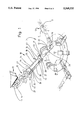
- FIG. 2 shows a shaping station as a part of the apparatus according to FIG. 1, on an enlarged scale, also in a perspective view,
- FIG. 3 shows a cross-sectional view of FIG. 2 with an actuating gear for shaping tools.
- the exemplary embodiment shown in the drawings relates to the production of hinge-lid packs 10 whose forward and/or rearward longitudinal edges 11, 12 are rounded. Thereby, a hinge-lid pack with the design according to U.S. Pat. No. 4,753,383 is formed.
- the folding turret 17 may be designed in the manner described in U.S. Pat. No. 4,084,393.
- a shaping station 18 is arranged upstream of the folding turret 17 in the region of the blank track 16.
- the longitudinal edges 11, 12, in the region of the otherwise flat, unfolded blank are pre-shaped in the manner of a chamfer.
- the pre-shaped blank is then fed to the folding turret 17 on the blank track 16 and further processed in the usual manner.
- the shaping station 18 is provided with at least one shaping device 19.
- This shaping device 19 is comprised of one stationary shaping tool, specifically a shaping plate 20, and two movable shaping tools, specifically shaping rollers 21 and 22.
- the shaping plate 20 is designed with shaping margins 23, 24 extending in the lateral direction which correspond to the contour of the longitudinal edge 11, 12 to be produced. In the present case, the shaping margins 23, 24 are thus round.
- the shaping plate 20 is adapted to the dimensions of the blank 14. Lateral regions of the same laterally project from the shaping plate 20 in the starting position. These lateral regions are side tabs 25, 26 which are conventional in a blank 14 for hinge-lid packs 10. These side tabs are pressed against the shaping margins 23, 24 when pro-shaping the blank so that, in the region between the side tabs 25 and 26, on the one hand, and a central region of the blank 14, the rounded edges 11 are formed.
- the blank 14 is transported into the shaping station 18 on the blank track 16 by means of transport rollers 27, specifically in such a manner that the blank 14 rests below the shaping station 20.
- the blank is pressed against the bottom side of the shaping plate 20 by means of appropriate holding members, especially suction bores (not shown). The blank 14 thereby assumes the position shown in FIGS. 2 and 3.
- conveying discs 43 are assigned to the shaping plate 20. In the present case these are arranged on the shaping plate 20 itself.
- the conveying disc 43 with a lower region, enters into a longitudinal slot 43 at the end of the shaping plate 20.
- the conveying disc 43 interacts with an additional conveying disc (not shown) arranged below the shaping plate 20.
- One of the conveying discs 43 is arranged within close proximity of the transport rollers 27.
- shaping rollers 21, 22 take effect. These shaping rollers are located in a starting position below the blank 14.
- the shaping rollers 21, 22 are now moved along a first circular path of movement 28 along the contour of the shaping margins 23, thereby taking along the projecting parts of the blank 14, up to an upper position shown in dot-dash lines in FIG. 3. Thereby, the regions of the longitudinal edges 11, 12 are adjoined to the shaping margins 23, 24 under pressure.
- the shaping rollers 21, 22 return to their starting position, specifically below the shaping plate 20. Thereby, the shaping rollers are moved along a path of movement 29. This is chosen such that the shaping rollers 21, 22 are moved sideways from an upper final position, and then downwards, and finally back into the starting position. As a result of the lateral movement of the shaping rollers 21, 22, they are entirely moved out of the region of the shaping plate 20 or the blank 14. Immediately after completion of the forming working cycle, the deformed blank 14 can thus be discharged, and a new, flat blank 14 can be supplied. This blank can already be located in the working position according to FIG. 2 when the shaping rollers 21, 22 reach the starting position (continuous lines in FIG. 3).
- the movement of the shaping rollers 21, 22 along the differently designed paths of movement 28, 29 is achieved by means of a special gearing.
- the shaping rollers 21, 22 are arranged on the upper, free end of an upright leg 31.
- a lifting drive 33 takes effect on a leg 32, which is horizontally directed in a starting position.
- This lifting drive 33 in the present case, is comprised of a linkage 34 which is essentially movable up and down and which is hingedly connected to the free end of the leg 32, on the one hand, and to the actuating lever 35, on the other. The latter is moved up and down in a pivoting manner in the vertical plane.
- the complex, superposed movement of the shaping rollers 21, 22 along a path of movement 28, 29 is achieved by the method of operation of another gearing which in this case is designed as a crank 36 with a crank arm 37.
- the crank 36 in the representation according to FIG. 3, is concealed behind toggle lever 30.
- This toggle lever 30 is connected to the crank arm 37 in the region of the pivot bearing 38, the pivot bearing 38 being located in the region of the juncture of the two legs 31, 32.
- a stationary crankshaft 39 is located above.
- the gearing formed by the crank 36 is in the first line responsible for the lateral movements of the shaping rollers 21, 22. This movement is superposed by the upward movement of the linkage 34.
- the crank arm 37 carries out a to and fro movement in the vertical plane, which is marked by an arrow of movement 40.
Abstract
In the production of hinge-lid packs with especially rounded longitudinally edges (11, 12) a blank (14) is pre-shaped in the region of a shaping station (18). To this end, the regions of the longitudinal edges (11, 12) of the blank (14) are pressed against shaping margins (23, 24) of a shaping plate (20) by shaping rollers (21, 22). To increase the performance of the shaping station (18), the shaping rollers (21, 22) are moved back into the starting position along a path of movement (29) which is located at a distance from the shaping plate (20). During this movement back into the starting position, the pre-shaped blank (14) can be discharged and a following blank can be moved into position.
Description
The invention relates to an apparatus for shaping or pre-shaping blanks for packs, especially hinge-lid packs with rounded or polygonal longitudinal edges, wherein the blanks can be fed to a shaping station having at least one shaping device comprised of a shaping plate with shaping longitudinal margins and movable shaping tools, especially shaping rollers, the movable shaping tools being movable along marginal regions of the shaping plate, especially from the bottom side of the shaping plate to the top side, thereby deforming the blank.
Hinge-lid packs are a widespread pack type for cigarettes. Recently, hinge-lid packs for cigarettes whose longitudinal edges have a rounded, beveled or polygonal design have been increasingly used. The production of such packs requires a preparatory treatment of the blanks, specifically a deformation of the same in the region of longitudinal edges. An example for an apparatus for shaping or pre-shaping blanks for hinge-lid packs is shown and described in U.S. Pat. No. 4,708,704 Focke et al (assigned to the assignee of the present application).
The present invention relates to a development or improvement of the apparatus according to U.S. Pat. No. 4,708,704, or similar shaping apparatuses for blanks.
The invention is based on the object to design an apparatus of the foregoing type in such a manner that a higher performance is attained when shaping or pre-shaping the blanks.
To attain this object, the apparatus according to the invention is characterized in that the movable shaping tools, especially shaping rollers, after carrying out a forming motion cycle, can be laterally lifted off the shaping plate and moved back into the starting position along a path of movement extending at a distance from the shaping plate.
Whereas in the state of the art according to U.S. Pat. No. 4,708,704, the shaping tools, specifically the shaping rollers, carry out an up and down movement in the region of the laterally rounded or trapezoidal shaping margins, the shaping tools, according to the invention, are moved out of the region of the shaping plate after completion of a forming working cycle, and moved back into the (lower) starting position at a significant distance from the shaping plate. Thereby, plenty of time is saved. When the shaping rollers are lifted off from the shaping plate in the upper position, the blank which has been processed by pre-shaping can already be discharged, and a following, unprocessed blank can be moved into the starting position. The advantage is in a significantly reduced cycle time of the shaping station.
For actuating the shaping rollers, a mechanical gearing comprised of a toggle lever for the shaping rollers, which is mounted pivotably and so as to be movable up and down, and two actuating drives, which take effect in a manner adapted to one another, are provided. This results in different paths of movement of the shaping tools during the working cycle, which preferably extends from the bottom to the top, on the one hand, and during the return into the starting position, on the other.
Further details of the apparatus according to the invention are explained hereinbelow with reference to the drawings, in which
FIG. 1 shows a diagrammatic representation of a portion of a packaging machine for hinge-lid packs,
FIG. 2 shows a shaping station as a part of the apparatus according to FIG. 1, on an enlarged scale, also in a perspective view,
FIG. 3 shows a cross-sectional view of FIG. 2 with an actuating gear for shaping tools.
The exemplary embodiment shown in the drawings relates to the production of hinge-lid packs 10 whose forward and/or rearward longitudinal edges 11, 12 are rounded. Thereby, a hinge-lid pack with the design according to U.S. Pat. No. 4,753,383 is formed.
For the production of such hinge-lid packs 10, unfolded blanks 14 are successively withdrawn from the bottom side of a conventional blank magazine 13. In the present embodiment, a roll-off device 15, which is conventional in practice, is active for this purpose.
After leaving the blank magazine 13, the blanks 14 are moved into a blank track 16. This blank track 16 leads to a folding turret 17, in the region of which the hinge-lid packs are largely completed and filled. The folding turret 17 may be designed in the manner described in U.S. Pat. No. 4,084,393.
A shaping station 18 is arranged upstream of the folding turret 17 in the region of the blank track 16. In the region of the shaping station 18, the longitudinal edges 11, 12, in the region of the otherwise flat, unfolded blank, are pre-shaped in the manner of a chamfer. The pre-shaped blank is then fed to the folding turret 17 on the blank track 16 and further processed in the usual manner.
The shaping station 18 is provided with at least one shaping device 19. This shaping device 19 is comprised of one stationary shaping tool, specifically a shaping plate 20, and two movable shaping tools, specifically shaping rollers 21 and 22. The shaping plate 20 is designed with shaping margins 23, 24 extending in the lateral direction which correspond to the contour of the longitudinal edge 11, 12 to be produced. In the present case, the shaping margins 23, 24 are thus round. The shaping plate 20 is adapted to the dimensions of the blank 14. Lateral regions of the same laterally project from the shaping plate 20 in the starting position. These lateral regions are side tabs 25, 26 which are conventional in a blank 14 for hinge-lid packs 10. These side tabs are pressed against the shaping margins 23, 24 when pro-shaping the blank so that, in the region between the side tabs 25 and 26, on the one hand, and a central region of the blank 14, the rounded edges 11 are formed.
In the present exemplary embodiment, the blank 14 is transported into the shaping station 18 on the blank track 16 by means of transport rollers 27, specifically in such a manner that the blank 14 rests below the shaping station 20. The blank is pressed against the bottom side of the shaping plate 20 by means of appropriate holding members, especially suction bores (not shown). The blank 14 thereby assumes the position shown in FIGS. 2 and 3.
In order to ensure an accurate positioning of the blank during the transfer to the shaping plate 20, conveying discs 43 are assigned to the shaping plate 20. In the present case these are arranged on the shaping plate 20 itself. The conveying disc 43, with a lower region, enters into a longitudinal slot 43 at the end of the shaping plate 20. The conveying disc 43 interacts with an additional conveying disc (not shown) arranged below the shaping plate 20. One of the conveying discs 43 is arranged within close proximity of the transport rollers 27. Thus, for the transfer of the blank 14 to the shaping plate 20, the blank is guided by a plurality of members.
Now the shaping rollers 21, 22 take effect. These shaping rollers are located in a starting position below the blank 14. The shaping rollers 21, 22 are now moved along a first circular path of movement 28 along the contour of the shaping margins 23, thereby taking along the projecting parts of the blank 14, up to an upper position shown in dot-dash lines in FIG. 3. Thereby, the regions of the longitudinal edges 11, 12 are adjoined to the shaping margins 23, 24 under pressure.
After this forming working cycle, the shaping rollers 21, 22 return to their starting position, specifically below the shaping plate 20. Thereby, the shaping rollers are moved along a path of movement 29. This is chosen such that the shaping rollers 21, 22 are moved sideways from an upper final position, and then downwards, and finally back into the starting position. As a result of the lateral movement of the shaping rollers 21, 22, they are entirely moved out of the region of the shaping plate 20 or the blank 14. Immediately after completion of the forming working cycle, the deformed blank 14 can thus be discharged, and a new, flat blank 14 can be supplied. This blank can already be located in the working position according to FIG. 2 when the shaping rollers 21, 22 reach the starting position (continuous lines in FIG. 3).
The movement of the shaping rollers 21, 22 along the differently designed paths of movement 28, 29 is achieved by means of a special gearing. According to the exemplary embodiment of FIG. 3, the shaping rollers 21, 22 are arranged on the upper, free end of an upright leg 31. A lifting drive 33 takes effect on a leg 32, which is horizontally directed in a starting position. This lifting drive 33, in the present case, is comprised of a linkage 34 which is essentially movable up and down and which is hingedly connected to the free end of the leg 32, on the one hand, and to the actuating lever 35, on the other. The latter is moved up and down in a pivoting manner in the vertical plane.
The complex, superposed movement of the shaping rollers 21, 22 along a path of movement 28, 29 is achieved by the method of operation of another gearing which in this case is designed as a crank 36 with a crank arm 37. The crank 36, in the representation according to FIG. 3, is concealed behind toggle lever 30. This toggle lever 30 is connected to the crank arm 37 in the region of the pivot bearing 38, the pivot bearing 38 being located in the region of the juncture of the two legs 31, 32. A stationary crankshaft 39 is located above.
The gearing formed by the crank 36 is in the first line responsible for the lateral movements of the shaping rollers 21, 22. This movement is superposed by the upward movement of the linkage 34. The crank arm 37 carries out a to and fro movement in the vertical plane, which is marked by an arrow of movement 40. The juncture between the linkage 34 and the leg 32, specifically a pivot bearing 41, thereby moves along a complex path of movement 42 which has approximately the shape of an "8".
Further constructive details of the shaping station may be designed according to U.S. Pat No. 4,708,704. This especially applies to the conveying members for the discharge of the blanks. The movement of the shaping tools, specifically of the shaping rollers 21, 22, may also be effected in the opposite direction. In this case, the blank 14 is positioned on the upper side of the shaping plate.
Claims (3)
1. An apparatus for shaping or pre-shaping blanks (14) for enclosed boxes with rounded or polygonal longitudinal edges (11, 12), said apparatus comprising:
a) a shaping station having at least one shaping device (19); and
b) means for feeding the blanks (14) along a track (16) in a conveying direction into said shaping station (18) so that the longitudinal edges (11, 12) of the blank extend in the conveying direction of the blank (14) and are shaped by said shaping device (19);
c) wherein said shaping device (19) comprises: a stationary shaping plate (20) and two movable longitudinally extending shaping rollers (21, 22), the shaping plate (20) having shaping longitudinal margins (23, 24) with a contour corresponding to the shape of the longitudinal edges (11, 12) of each blank, the shaping rollers being parallel to the longitudinal margins (23, 24); and means for moving the shaping rollers from one position, which is beneath the blank (14) and in which the shaping rollers are pressed against the blank along the longitudinal margins (23, 24), to an upper side of the shaping plate (20) and then back to a starting position; and
d) means for moving the shaping rollers (21, 22), after a shaping cycle has been carried out, from an end position above the shaping plate (20) along an arcuate path of motion (29), then laterally, and then for returning the shaping rollers (21, 22) to the starting position located beneath the shaping plate (20), so that the path of motion (29) along which the shaping rollers (21, 22) are returned runs outside of an area of the unshaped, flat blank (14).
2. The apparatus according to claim 1, comprising:
a lifting drive (33) for moving each shaping roller (21, 22); and
at least one two-armed angled toggle-lever (30) to which each shaping roller (21, 22) is attached;
wherein the angled lever (30) has a free shank (32) connected to the lifting drive (33);
wherein said lifting drive comprises an actuating lever (35), pivotally mounted for up and down movement in a vertical plane, and a linkage (34) which is connected to one side of the actuating lever (35) and on another side to one (32) of two legs (31, 32) of the angled lever (30);
wherein the angled lever (30) is pivotally mounted to a pivot bearing (38) located at a juncture of the two legs (31, 32) of the angled lever; and
wherein the angled lever (30), along with its pivot bearing (38), is connected to a free end of a crank arm (37) of a fixedly positioned crank (36), said crank arm rotating around a stationary crank shaft bearing (39).
3. An apparatus according to claim 1, further comprising conveying discs (43), wherein the blanks (14) are conveyed out of the shaping station (18) in the conveying direction, after shaping by the shaping rollers (21, 22), and during the return to the lower starting position, by said conveying discs (43) which are located in longitudinal slots (44) of the shaping plate and act in rearward and forward end regions of the shaping plate (20), relative to the conveying direction, and which grip the blank (14) in a central area thereof in a perpendicular direction and discharge the blank.
Applications Claiming Priority (2)
| Application Number | Priority Date | Filing Date | Title |
|---|---|---|---|
| DE4404289.2 | 1994-02-11 | ||
| DE4404289A DE4404289A1 (en) | 1994-02-11 | 1994-02-11 | Device for the shaping treatment of blanks, in particular for hinged boxes |
Publications (1)
| Publication Number | Publication Date |
|---|---|
| US5549537A true US5549537A (en) | 1996-08-27 |
Family
ID=6509991
Family Applications (1)
| Application Number | Title | Priority Date | Filing Date |
|---|---|---|---|
| US08/386,627 Expired - Lifetime US5549537A (en) | 1994-02-11 | 1995-02-10 | Apparatus for the shaping treatment of blanks, especially for hinge-lid packs |
Country Status (5)
| Country | Link |
|---|---|
| US (1) | US5549537A (en) |
| EP (1) | EP0667230B1 (en) |
| JP (1) | JP3165345B2 (en) |
| CN (1) | CN1079729C (en) |
| DE (2) | DE4404289A1 (en) |
Cited By (16)
| Publication number | Priority date | Publication date | Assignee | Title |
|---|---|---|---|---|
| US6206815B1 (en) * | 1997-06-20 | 2001-03-27 | Focke & Co. (Gmbh & Co.) | Method and device for manufacturing hinge-lid packets |
| US20020033001A1 (en) * | 2000-09-15 | 2002-03-21 | Karsten Meinke | Device and method for transferring foldable blanks from a transfer station to a processing station |
| US20030168614A1 (en) * | 2002-03-09 | 2003-09-11 | Kimberly-Clark Worldwide, Inc. | Apparatus and method for inspecting pre-fastened articles |
| US20030169433A1 (en) * | 2002-03-09 | 2003-09-11 | Kimberly-Clark Worldwide, Inc. | Process for the detection of marked components of a composite article using infrared blockers |
| US20040022426A1 (en) * | 2002-07-31 | 2004-02-05 | Kimberly-Clark Worldwide, Inc. | Apparatus and method for inspecting articles |
| EP1396430A2 (en) | 2002-09-06 | 2004-03-10 | Focke & Co. (GmbH & Co.) | Procedure for the production of hinged lid boxes |
| US6885451B2 (en) | 2002-03-09 | 2005-04-26 | Kimberly-Clark Worldwide, Inc. | Infrared detection of composite article components |
| US20050096203A1 (en) * | 2003-10-08 | 2005-05-05 | G.D Societa' Per Azioni | Method and unit for flexing a flat blank for producing a rigid package |
| US6900450B2 (en) | 2002-03-09 | 2005-05-31 | Kimberly-Clark Worldwide, Inc. | Method and apparatus for inferring item position based on multiple data |
| US20050126120A1 (en) * | 2003-11-13 | 2005-06-16 | G.D Societa' Per Azioni | Packing machine |
| US6919965B2 (en) | 2002-03-09 | 2005-07-19 | Kimberly-Clark Worldwide, Inc. | Apparatus and method for making and inspecting pre-fastened articles |
| US20050164858A1 (en) * | 2001-03-28 | 2005-07-28 | Heinz Focke | Packaging machine for cigarettes |
| US20060094580A1 (en) * | 2004-11-01 | 2006-05-04 | Hudson-Sharp Machine Co. | Apparatus for sealing bag bottom |
| US20100056352A1 (en) * | 2006-07-20 | 2010-03-04 | Uwe Stroinski | Method and device for producing a highly precise box |
| US20110092350A1 (en) * | 2009-10-21 | 2011-04-21 | Wilkinson Richard W | Systems and methods for folding |
| SE2151508A1 (en) * | 2021-12-10 | 2023-06-11 | Stora Enso Oyj | Method and apparatus for manufacturing folded packaging products |
Families Citing this family (2)
| Publication number | Priority date | Publication date | Assignee | Title |
|---|---|---|---|---|
| DE102004024431A1 (en) * | 2004-05-14 | 2005-12-08 | Focke & Co.(Gmbh & Co. Kg) | Apparatus for producing cigarette packs |
| DE102010050528A1 (en) | 2010-11-10 | 2012-05-10 | Focke & Co. (Gmbh & Co. Kg) | Device for handling blanks in packaging machines |
Citations (8)
| Publication number | Priority date | Publication date | Assignee | Title |
|---|---|---|---|---|
| US2609736A (en) * | 1948-06-03 | 1952-09-09 | Hugh E Montgomery | Machine for folding paper box blanks on a stack thereof |
| US3514097A (en) * | 1967-11-13 | 1970-05-26 | Gen Binding Corp Canada Ltd | Folding apparatus for paper and the like |
| GB1381847A (en) * | 1972-08-25 | 1975-01-29 | Tetra Pak Dev | Method of and means for forming a container blank into a tubular body |
| US4469542A (en) * | 1982-09-07 | 1984-09-04 | Tetra Pak Developpement | Method of making a piece of tube from a flat web of flexible material, and apparatus for carrying out the method |
| DE3515775A1 (en) * | 1985-05-02 | 1986-11-06 | Focke & Co (GmbH & Co), 2810 Verden | METHOD AND DEVICE FOR PRODUCING PACKS WITH ROUNDED OR BEVELED EDGES |
| DE3805050A1 (en) * | 1987-04-02 | 1988-10-13 | Nagema Veb K | Device for pre-folding the bag closure in packing machines |
| US5184998A (en) * | 1991-04-08 | 1993-02-09 | Volk Packaging Corporation | Corrugated cardboard or chipboard carton forming machine |
| DE4209141A1 (en) * | 1992-03-20 | 1993-09-23 | Kettner Verpackungsmaschf | Packaging carton erection machine from blank - has prefolding die set above mouth of blank magazine, with pref. two folders in front of main folding die |
-
1994
- 1994-02-11 DE DE4404289A patent/DE4404289A1/en not_active Withdrawn
-
1995
- 1995-02-01 EP EP95101320A patent/EP0667230B1/en not_active Expired - Lifetime
- 1995-02-01 DE DE59500293T patent/DE59500293D1/en not_active Expired - Lifetime
- 1995-02-10 US US08/386,627 patent/US5549537A/en not_active Expired - Lifetime
- 1995-02-11 CN CN95101508A patent/CN1079729C/en not_active Expired - Fee Related
- 1995-02-13 JP JP02421295A patent/JP3165345B2/en not_active Expired - Lifetime
Patent Citations (9)
| Publication number | Priority date | Publication date | Assignee | Title |
|---|---|---|---|---|
| US2609736A (en) * | 1948-06-03 | 1952-09-09 | Hugh E Montgomery | Machine for folding paper box blanks on a stack thereof |
| US3514097A (en) * | 1967-11-13 | 1970-05-26 | Gen Binding Corp Canada Ltd | Folding apparatus for paper and the like |
| GB1381847A (en) * | 1972-08-25 | 1975-01-29 | Tetra Pak Dev | Method of and means for forming a container blank into a tubular body |
| US4469542A (en) * | 1982-09-07 | 1984-09-04 | Tetra Pak Developpement | Method of making a piece of tube from a flat web of flexible material, and apparatus for carrying out the method |
| DE3515775A1 (en) * | 1985-05-02 | 1986-11-06 | Focke & Co (GmbH & Co), 2810 Verden | METHOD AND DEVICE FOR PRODUCING PACKS WITH ROUNDED OR BEVELED EDGES |
| US4708704A (en) * | 1985-05-02 | 1987-11-24 | Focke & Co. (Gmbh & Co.) | Process for producing packs with rounded or bevelled edges |
| DE3805050A1 (en) * | 1987-04-02 | 1988-10-13 | Nagema Veb K | Device for pre-folding the bag closure in packing machines |
| US5184998A (en) * | 1991-04-08 | 1993-02-09 | Volk Packaging Corporation | Corrugated cardboard or chipboard carton forming machine |
| DE4209141A1 (en) * | 1992-03-20 | 1993-09-23 | Kettner Verpackungsmaschf | Packaging carton erection machine from blank - has prefolding die set above mouth of blank magazine, with pref. two folders in front of main folding die |
Cited By (32)
| Publication number | Priority date | Publication date | Assignee | Title |
|---|---|---|---|---|
| US6206815B1 (en) * | 1997-06-20 | 2001-03-27 | Focke & Co. (Gmbh & Co.) | Method and device for manufacturing hinge-lid packets |
| US20020033001A1 (en) * | 2000-09-15 | 2002-03-21 | Karsten Meinke | Device and method for transferring foldable blanks from a transfer station to a processing station |
| US7146777B2 (en) * | 2001-03-28 | 2006-12-12 | Focke & Co. (Gmbh & Co.) | Packaging machine for cigarettes |
| EP1372945B1 (en) * | 2001-03-28 | 2005-09-14 | Focke & Co. (GmbH & Co. KG) | Packaging machine for cigarettes |
| US20050164858A1 (en) * | 2001-03-28 | 2005-07-28 | Heinz Focke | Packaging machine for cigarettes |
| US6919965B2 (en) | 2002-03-09 | 2005-07-19 | Kimberly-Clark Worldwide, Inc. | Apparatus and method for making and inspecting pre-fastened articles |
| US20030169433A1 (en) * | 2002-03-09 | 2003-09-11 | Kimberly-Clark Worldwide, Inc. | Process for the detection of marked components of a composite article using infrared blockers |
| US6888143B2 (en) | 2002-03-09 | 2005-05-03 | Kimberly-Clark Worldwide, Inc. | Apparatus and method for inspecting pre-fastened articles |
| US20030168614A1 (en) * | 2002-03-09 | 2003-09-11 | Kimberly-Clark Worldwide, Inc. | Apparatus and method for inspecting pre-fastened articles |
| US6900450B2 (en) | 2002-03-09 | 2005-05-31 | Kimberly-Clark Worldwide, Inc. | Method and apparatus for inferring item position based on multiple data |
| US20050122531A1 (en) * | 2002-03-09 | 2005-06-09 | Kimberly-Clark Worldwide, Inc. | Process for the detection of marked components of a composite article using infrared blockers |
| US7935296B2 (en) | 2002-03-09 | 2011-05-03 | Kimberly-Clark Worldwide, Inc. | Process for the detection of marked components of a composite article using infrared blockers |
| US6885451B2 (en) | 2002-03-09 | 2005-04-26 | Kimberly-Clark Worldwide, Inc. | Infrared detection of composite article components |
| US6927857B2 (en) | 2002-03-09 | 2005-08-09 | Kimberly-Clark Worldwide, Inc. | Process for the detection of marked components of a composite article using infrared blockers |
| US20040022426A1 (en) * | 2002-07-31 | 2004-02-05 | Kimberly-Clark Worldwide, Inc. | Apparatus and method for inspecting articles |
| US7123765B2 (en) | 2002-07-31 | 2006-10-17 | Kimberly-Clark Worldwide, Inc. | Apparatus and method for inspecting articles |
| EP1396430A3 (en) * | 2002-09-06 | 2005-09-21 | Focke & Co. (GmbH & Co. KG) | Procedure for the production of hinged lid boxes |
| US7001320B1 (en) * | 2002-09-06 | 2006-02-21 | Focke & Co., (Gmbh & Co) | Process for producing hinge-lid boxes |
| EP1396430A2 (en) | 2002-09-06 | 2004-03-10 | Focke & Co. (GmbH & Co.) | Procedure for the production of hinged lid boxes |
| US20050096203A1 (en) * | 2003-10-08 | 2005-05-05 | G.D Societa' Per Azioni | Method and unit for flexing a flat blank for producing a rigid package |
| US7104943B2 (en) * | 2003-10-08 | 2006-09-12 | G.D Societa' Per Azionivia | Method and unit for flexing a flat blank for producing a rigid package |
| US7062890B2 (en) * | 2003-11-13 | 2006-06-20 | G.D Societa' Per Azioni | Packing machine |
| US20050126120A1 (en) * | 2003-11-13 | 2005-06-16 | G.D Societa' Per Azioni | Packing machine |
| US20060094580A1 (en) * | 2004-11-01 | 2006-05-04 | Hudson-Sharp Machine Co. | Apparatus for sealing bag bottom |
| US7172546B2 (en) * | 2004-11-01 | 2007-02-06 | Hudson-Sharp Machine Co. | Apparatus for sealing bag bottom |
| US20100056352A1 (en) * | 2006-07-20 | 2010-03-04 | Uwe Stroinski | Method and device for producing a highly precise box |
| US8343023B2 (en) * | 2006-07-20 | 2013-01-01 | Robert Bosch Gmbh | Method and device for producing a highly precise box |
| US20110092350A1 (en) * | 2009-10-21 | 2011-04-21 | Wilkinson Richard W | Systems and methods for folding |
| US8246527B2 (en) * | 2009-10-21 | 2012-08-21 | J&L Group International, Llc | Systems and methods for folding |
| SE2151508A1 (en) * | 2021-12-10 | 2023-06-11 | Stora Enso Oyj | Method and apparatus for manufacturing folded packaging products |
| WO2023105311A1 (en) * | 2021-12-10 | 2023-06-15 | Stora Enso Oyj | Method and apparatus for manufacturing folded packaging products |
| SE545816C2 (en) * | 2021-12-10 | 2024-02-13 | Stora Enso Oyj | Method and apparatus for manufacturing folded packaging products |
Also Published As
| Publication number | Publication date |
|---|---|
| EP0667230A1 (en) | 1995-08-16 |
| CN1115282A (en) | 1996-01-24 |
| DE59500293D1 (en) | 1997-07-17 |
| JPH0811203A (en) | 1996-01-16 |
| CN1079729C (en) | 2002-02-27 |
| DE4404289A1 (en) | 1995-08-17 |
| JP3165345B2 (en) | 2001-05-14 |
| EP0667230B1 (en) | 1997-06-11 |
Similar Documents
| Publication | Publication Date | Title |
|---|---|---|
| US5549537A (en) | Apparatus for the shaping treatment of blanks, especially for hinge-lid packs | |
| US3633470A (en) | Package feeder apparatus | |
| JP2010506762A (en) | Machine to form cardboard box blank | |
| US4917663A (en) | Packaging machine with direct blank setup | |
| US4100842A (en) | Apparatus for forming a container | |
| US7001320B1 (en) | Process for producing hinge-lid boxes | |
| US3776109A (en) | Folder for large box blanks | |
| JPH0116217B2 (en) | ||
| US4693051A (en) | Machine for boxing items in groups | |
| US5050855A (en) | Apparatus for extracting (pack) blanks from a blank magazine | |
| US3733980A (en) | Carton gluing machine and method | |
| JPH0787232B2 (en) | Press machine | |
| US3038387A (en) | Carton setting up machine | |
| JPH0516903A (en) | Wraparound packaging apparatus | |
| US3001506A (en) | Machine for applying sealing compound to bottle caps | |
| KR100453192B1 (en) | Packaging manufacturing apparatus | |
| WO1988009291A1 (en) | Packaging machine with direct blank setup | |
| EP0123398B1 (en) | Method of and apparatus for transporting workpieces into and out of a press or other workstation | |
| US2970527A (en) | Flange bending machine for unstayed set-up box manufacture | |
| CN111331926A (en) | Box pasting machine for three-dimensional plug bush without book wall | |
| US3386349A (en) | Box making machine | |
| EP0154911B1 (en) | A feeding apparatus for wrapping machines | |
| JPS6010821B2 (en) | Automatic feeding device of press machine | |
| JPS5931369Y2 (en) | roof tile forming machine | |
| US2704918A (en) | Packaging apparatus |
Legal Events
| Date | Code | Title | Description |
|---|---|---|---|
| FEPP | Fee payment procedure |
Free format text: PAYOR NUMBER ASSIGNED (ORIGINAL EVENT CODE: ASPN); ENTITY STATUS OF PATENT OWNER: LARGE ENTITY |
|
| AS | Assignment |
Owner name: FOCKE & CO. (GMBH & CO.), GERMANY Free format text: ASSIGNMENT OF ASSIGNORS INTEREST;ASSIGNORS:FOCKE, HEINZ;GRANZ, HELMUT;REEL/FRAME:007985/0603 Effective date: 19950130 |
|
| STCF | Information on status: patent grant |
Free format text: PATENTED CASE |
|
| FPAY | Fee payment |
Year of fee payment: 4 |
|
| FPAY | Fee payment |
Year of fee payment: 8 |
|
| FPAY | Fee payment |
Year of fee payment: 12 |