US5600953A - Compressed air control apparatus - Google Patents

Compressed air control apparatus Download PDF

Info

Publication number
US5600953A
US5600953A US08/533,746 US53374695A US5600953A US 5600953 A US5600953 A US 5600953A US 53374695 A US53374695 A US 53374695A US 5600953 A US5600953 A US 5600953A
Authority
US
United States
Prior art keywords
valve
housing
compressed air
dry
control apparatus
Prior art date
Legal status (The legal status is an assumption and is not a legal conclusion. Google has not performed a legal analysis and makes no representation as to the accuracy of the status listed.)
Expired - Lifetime
Application number
US08/533,746
Inventor
Morito Oshita
Masakazu Ozawa
Masayoshi Hattori
Current Assignee (The listed assignees may be inaccurate. Google has not performed a legal analysis and makes no representation or warranty as to the accuracy of the list.)
Aisin Corp
Original Assignee
Aisin Seiki Co Ltd
Priority date (The priority date is an assumption and is not a legal conclusion. Google has not performed a legal analysis and makes no representation as to the accuracy of the date listed.)
Filing date
Publication date
Priority claimed from JP23386794A external-priority patent/JPH0893647A/en
Priority claimed from JP20245995A external-priority patent/JPH08151978A/en
Application filed by Aisin Seiki Co Ltd filed Critical Aisin Seiki Co Ltd
Assigned to AISIN SEIKI KABUSHIKI KAISHA reassignment AISIN SEIKI KABUSHIKI KAISHA ASSIGNMENT OF ASSIGNORS INTEREST (SEE DOCUMENT FOR DETAILS). Assignors: HATTORI, MASAYOSHI, OSHITA, MORITO, OZAWA, MASAKAZU
Application granted granted Critical
Publication of US5600953A publication Critical patent/US5600953A/en
Anticipated expiration legal-status Critical
Expired - Lifetime legal-status Critical Current

Links

Images

Classifications

    • BPERFORMING OPERATIONS; TRANSPORTING
    • B60VEHICLES IN GENERAL
    • B60GVEHICLE SUSPENSION ARRANGEMENTS
    • B60G17/00Resilient suspensions having means for adjusting the spring or vibration-damper characteristics, for regulating the distance between a supporting surface and a sprung part of vehicle or for locking suspension during use to meet varying vehicular or surface conditions, e.g. due to speed or load
    • B60G17/02Spring characteristics, e.g. mechanical springs and mechanical adjusting means
    • B60G17/04Spring characteristics, e.g. mechanical springs and mechanical adjusting means fluid spring characteristics
    • B60G17/052Pneumatic spring characteristics
    • B60G17/0523Regulating distributors or valves for pneumatic springs
    • FMECHANICAL ENGINEERING; LIGHTING; HEATING; WEAPONS; BLASTING
    • F04POSITIVE - DISPLACEMENT MACHINES FOR LIQUIDS; PUMPS FOR LIQUIDS OR ELASTIC FLUIDS
    • F04BPOSITIVE-DISPLACEMENT MACHINES FOR LIQUIDS; PUMPS
    • F04B39/00Component parts, details, or accessories, of pumps or pumping systems specially adapted for elastic fluids, not otherwise provided for in, or of interest apart from, groups F04B25/00 - F04B37/00
    • F04B39/12Casings; Cylinders; Cylinder heads; Fluid connections
    • F04B39/125Cylinder heads
    • FMECHANICAL ENGINEERING; LIGHTING; HEATING; WEAPONS; BLASTING
    • F04POSITIVE - DISPLACEMENT MACHINES FOR LIQUIDS; PUMPS FOR LIQUIDS OR ELASTIC FLUIDS
    • F04BPOSITIVE-DISPLACEMENT MACHINES FOR LIQUIDS; PUMPS
    • F04B39/00Component parts, details, or accessories, of pumps or pumping systems specially adapted for elastic fluids, not otherwise provided for in, or of interest apart from, groups F04B25/00 - F04B37/00
    • F04B39/16Filtration; Moisture separation
    • FMECHANICAL ENGINEERING; LIGHTING; HEATING; WEAPONS; BLASTING
    • F15FLUID-PRESSURE ACTUATORS; HYDRAULICS OR PNEUMATICS IN GENERAL
    • F15BSYSTEMS ACTING BY MEANS OF FLUIDS IN GENERAL; FLUID-PRESSURE ACTUATORS, e.g. SERVOMOTORS; DETAILS OF FLUID-PRESSURE SYSTEMS, NOT OTHERWISE PROVIDED FOR
    • F15B21/00Common features of fluid actuator systems; Fluid-pressure actuator systems or details thereof, not covered by any other group of this subclass
    • F15B21/04Special measures taken in connection with the properties of the fluid
    • F15B21/041Removal or measurement of solid or liquid contamination, e.g. filtering
    • BPERFORMING OPERATIONS; TRANSPORTING
    • B60VEHICLES IN GENERAL
    • B60GVEHICLE SUSPENSION ARRANGEMENTS
    • B60G2500/00Indexing codes relating to the regulated action or device
    • B60G2500/20Spring action or springs
    • B60G2500/201Air spring system type
    • B60G2500/2012Open systems
    • BPERFORMING OPERATIONS; TRANSPORTING
    • B60VEHICLES IN GENERAL
    • B60GVEHICLE SUSPENSION ARRANGEMENTS
    • B60G2500/00Indexing codes relating to the regulated action or device
    • B60G2500/20Spring action or springs
    • B60G2500/205Air-compressor operation
    • FMECHANICAL ENGINEERING; LIGHTING; HEATING; WEAPONS; BLASTING
    • F05INDEXING SCHEMES RELATING TO ENGINES OR PUMPS IN VARIOUS SUBCLASSES OF CLASSES F01-F04
    • F05CINDEXING SCHEME RELATING TO MATERIALS, MATERIAL PROPERTIES OR MATERIAL CHARACTERISTICS FOR MACHINES, ENGINES OR PUMPS OTHER THAN NON-POSITIVE-DISPLACEMENT MACHINES OR ENGINES
    • F05C2225/00Synthetic polymers, e.g. plastics; Rubber

Landscapes

  • Engineering & Computer Science (AREA)
  • Mechanical Engineering (AREA)
  • General Engineering & Computer Science (AREA)
  • Chemical & Material Sciences (AREA)
  • Analytical Chemistry (AREA)
  • Physics & Mathematics (AREA)
  • Fluid Mechanics (AREA)
  • Vehicle Body Suspensions (AREA)
  • Compressor (AREA)

Abstract

The invention is directed to a compressed air control apparatus for supplying compressed air to a pneumatic actuator, which includes a compressor having a head member with a pressure chamber defined therein for generating compressed air, an intake valve for introducing air into the pressure chamber, and a discharge valve for discharging the compressed air. A dryer is disposed in a dry housing to dry the compressed air discharged from the compressor. A supply solenoid valve is disposed in a supply valve housing to control the compressed air supplied to the pneumatic actuator. An exhaust solenoid valve is disposed in an exhaust valve housing to control the compressed air discharged from the pneumatic actuator. The head member, dry housing, supply valve housing and exhaust valve housing are integrally formed by synthetic resin to provide an integral housing.

Description

BACKGROUND OF THE INVENTION
1. Field of the Invention
The present invention relates to a compressed air control apparatus, more particularly to the apparatus having an integrally molded housing for use in a vehicle height control system which is provided with a pneumatic suspension unit.
2. Description of the Prior Arts
Various pneumatic suspension units for vehicles have been known heretofore. Among them, such an apparatus having its components assembled together has been employed in a vehicle as disclosed in a service manual of "LEGACY" (Trademark of Fuji Heavy Industries Ltd.) which was issued in October, 1993, for example, pages 4-34 to 4-40 and page 4-51. The apparatus includes a compressor having a cylinder head which is made of aluminium alloy and in which an intake valve and a discharge valve are assembled, and having a motor which is connected to the compressor to drive the same for discharging compressed air to a pneumatic suspension unit. The apparatus further includes an exhaust solenoid valve which is mounted on the compressor for controlling the compressed air discharged from the pneumatic suspension unit. Also assembled to the compressor is an air dryer with a housing made of synthetic resin for drying the compressed air to be supplied to the pneumatic suspension unit. Thus, the compressor, the exhaust solenoid valve and the air dryer are assembled as one body. With respect to a supply solenoid valve for controlling the compressed air to be supplied to the pneumatic suspension unit, however, it is arranged independently, or positioned separately from the compressor and other components.
According to the prior apparatus as described above, the cylinder head of the compressor and the housing of the air dryer are formed separately and then connected with each other, so that it is necessary to apply a sealing member to the connected portion so as to provide an air tight sealing. As a result, the prior apparatus is high in cost. Furthermore, the compressor includes the intake valve and the discharge valve, both of which have components generally made of metals different from the aluminium alloy, such as a spring or the like. If moisture was introduced into the cylinder head by accident, therefore, galvanic corrosion or electrolytic corrosion might be caused thereby to deteriorate the operation of the valves.
Also disclosed in Japanese Utility-model Publication No.2-33866, is an air dryer which is disposed between a compressed air source and a pneumatic machine, such as a vehicle height control apparatus. The air dryer includes a residual valve member and a check valve which are integrally formed as a sheet-like valve. According to this air dryer, however, the dryer is formed separately from an air compressor and a valve body for supplying the atmospheric air into the compressor and discharging the compressed air, so that sealing members are needed for the respective connected portions. With respect to the air intake valve, Japanese Utility model Laid-open Publication No. 62-69673 discloses a reed valve which includes a valve plate and a bent back plate, which are overlapped with each other and secured by a bolt or the like. According to this reed valve, however, it is difficult to install it in the cylinder head of the compressor.
SUMMARY OF THE INVENTION
Accordingly, it is an object of the present invention to provide a compressed air control apparatus with a relatively small number of components and relatively low in cost.
It is another object of the present invention to provide the compressed air control apparatus having a housing integrally formed with a plurality of housing members of components.
In accomplishing these and other objects, a compressed air control apparatus for supplying compressed air to a pneumatic actuator includes a compressor which defines in a head member a pressure chamber for generating the compressed air. An intake valve is provided for introducing air into the pressure chamber, and a discharge valve is provided for discharging the compressed air. A dryer is disposed in a dry housing for drying the compressed air discharged from the compressor. A supply solenoid valve is disposed in a supply valve housing for controlling the compressed air to be supplied to the pneumatic actuator. An exhaust solenoid valve is disposed in an exhaust valve housing for controlling the compressed air to be discharged from the pneumatic actuator. With respect to the housing members, the head member, dry housing, supply valve housing and exhaust valve housing are integrally formed by synthetic resin to provide an integral housing.
Preferably, the apparatus may further include a cap member which is connected to the dry housing to define therein a dry chamber, and which is formed with a passage, one end of which is communicated with the dry chamber, and the other end of which is communicated with the pneumatic actuator.
The integral housing preferably forms therein an intake passage which communicates the intake valve of the compressor with the atmosphere, and an exhaust passage which communicates the discharge valve of the compressor with both of the dry chamber and the exhaust solenoid valve. The supply solenoid valve and the exhaust solenoid valve may be assembled next to each other so as to form a single solenoid valve unit.
Preferably, a metallic mounting member is integrally molded to the integral housing in the vicinity of the intake valve of the compressor. The intake valve may include a reed valve, one end portion of which is secured to the metallic mounting member. The compressor includes a metallic cylinder having an opening end, on which a recess is formed so as to be engaged with the other end portion of the reed valve, so that the recess allows the reed valve to move within a predetermined opening angle.
BRIEF DESCRIPTION OF THE DRAWINGS
The above stated objects and following description will become readily apparent with reference to the accompanying drawings, wherein like reference numerals denote like elements, and in which:
FIG. 1 is a general block diagram illustrating a compressed air control apparatus according to the present invention;
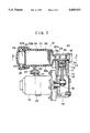
FIG. 2 is a sectional view of a compressed air control apparatus according to an embodiment of the present invention;
FIG. 3 is a sectional view taken along the line 3--3 in FIG. 2;
FIG. 4 is a sectional view taken along the line 4--4 in FIG. 3;
FIG. 5 is an enlarged sectional view of an intake valve of a compressor in an embodiment of the present invention; and
FIG. 6 is a sectional view of the intake valve in FIG. 5 as viewed from the downward.
DESCRIPTION OF THE PREFERRED EMBODIMENT
Referring to FIG. 1, there is shown an arrangement of components for a compressed air control apparatus, according to an embodiment of the present invention. A compressor 10 is operatively connected to an electric motor 15 which drives the compressor 10 to suck thereinto air from the atmosphere through a filter element 46 and an intake valve 25, and then compress the air. As arranged in FIG. 1, the air which is compressed by the compressor 10 is discharged from a discharge valve 26 and supplied into each of pneumatic suspension units AS, AS, which are provided for rear road wheels of a vehicle (not shown), through a filter element 33a, a dry room 34, a filter element 33b, a valve member 37 (i.e., a check valve 37a thereof), a filter element 47, a normally closed supply solenoid valve 38 and a filter element 49. Also, it is so arranged that the compressed air in each pneumatic suspension unit AS is exhausted to the atmosphere through the filter element 49, supply solenoid valve 38, filter element 47, valve member 37 (i.e., an orifice 37b thereof), filter element 33b, dry room 34, filter element 33a, filter element 45, normally closed exhaust solenoid valve 44 and filter element 46. Between the filter element 47 and the supply solenoid valve 38, there is disposed a relief valve 48.
As shown in FIG. 2, the compressor 10 includes a cylinder block 14 which is made of metal to define a cylindrical bore 13, and a piston 11 which is slidably received in the cylindrical bore 13. A circular groove 11a is formed around the periphery of the piston 11, and a piston ring 12 is fitted into the circular groove 11a. The piston 11 is connected to one end of a connecting rod 16 by a connecting pin 17, and slidably received in the cylindrical bore 13 with the piston ring 12 mounted around the piston 11. The other end of the connecting rod 16 is operatively connected to the motor 15, so that the piston 11 is driven by the motor 15 to reciprocate in the cylindrical bore 13. A cylinder head 20 is secured to an opening end of the cylinder block 14 to form a pressure chamber 50 between the piston 11 and the cylinder head 20 within the cylinder block 14. This cylinder head 20 is formed as a part of an integral housing 19, which further includes a dry housing 21, a supply valve housing 38a and an exhaust valve housing 44a, as shown in FIGS. 2 to 4. The integral housing 19 is made of synthetic resin having a good heat resistance property, such as PPS (polyphenylene sulfide) or the like, to integrate the cylinder head 20, dry housing 21, supply valve housing 38a and exhaust valve housing 44a, as shown in FIGS. 2 to 4. The dry housing 21 is integrally formed with a bracket 40 at its outer surface, as shown in FIG. 2. On the motor 15 is slidably mounted a belt 42 which integrates a bracket 41. The brackets 40 and 41 are bolted together by a bolt 43, so that the dry housing 21 is secured to the motor 15, which is secured to the cylinder block 14.
In a section of the integral housing 19 to provide the cylinder head 20, an intake passage 23 is formed to intake the air from the atmosphere, and a discharge passage 24 is formed to discharge the compressed air which is produced in the pressure chamber 50. In the intake passage 23, there is disposed the intake valve 25 which opens when the pressure in the pressure chamber 50 becomes less than a predetermined value. In the discharge passage 24, there is disposed the discharge valve 26 which opens when the pressure in the pressure chamber 50 becomes equal to or greater than a predetermined value, and which will be described later in detail referring to FIGS. 5 and 6.
As shown in FIGS. 2 and 3, the dry housing 21 is formed as a section of the integral housing 19 to provide a cylinder with its one end closed and the other end opened. In the closed end of the dry housing 21, a passage 28 is formed to communicate with the discharge passage 24, whereas the open end of the dry housing 21 is covered by a cap member 31 with an O-ring 30 disposed therebetween to provide an air tight seal. At both ends within the dry housing 21, there are disposed plates having a plurality of holes defined therein (hereinafter, referred to as perforated plates) 32a, 32b, which abut filter elements 33a, 33b, respectively. Therefore, the perforated plates 32a, 32b define the dry room 34 therebetween, in which a moisture absorbent 35 such as silica gel or the like is filled. A spring 36 is disposed between the perforated plate 32b and an end portion 31a of the cap member 31 for biasing the moisture absorbent 35 in the axial direction, so that elements of the moisture absorbent 35 tightly contact with each other, and the pressure in the dry housing 21 will not be affected by introducing thereinto the compressed air.
In parallel with the dry housing 21 as shown in FIG. 3, is formed an air passage 22, at one end of which the valve member 37 is disposed together with a filter element 47, and at the other one end of which the supply solenoid valve 38 is disposed as described later in detail. The air passage 22 is communicated with the dry housing 21 at the end portion 31a, through a passage 39 and the valve member 37, so that the compressed air which is dried in the dry room 34 can be introduced into the air passage 22. The valve member 37 includes the check valve 37a as shown in FIG. 1, which opens when the compressed and dried air is supplied to the pneumatic suspension unit AS, and includes the orifice 37b as shown in FIG. 1, through which the compressed air is discharged into the dry room 34.
The supply solenoid valve 38 is disposed at the other one end of the air passage 22 as shown in FIG. 4 to communicate with the air passage 22 and control the compressed air supplied to the pneumatic suspension unit AS. The supply solenoid valve 38 includes the supply valve housing 38a which is integrally formed with the integral housing 19, and next to which the exhaust valve housing 44a of the exhaust solenoid valve 44 is integrally formed. The exhaust solenoid valve 44 is provided for controlling the compressed air exhausted from the pneumatic suspension unit AS. Opposite to the supply solenoid valve 38, the relief valve 48 is disposed to communicate with the air passage 22, and it is so arranged that the relief valve 48 opens to the atomosphere, when the pressure in the air passage 22 exceeds a predetermined pressure thereby to decrease the pressure in the air passage 22. With the end portion of the air passage 22 and the exhaust port 27 formed nearby, the supply solenoid valve 38 and the exhaust solenoid valve 44 may be formed integrally to provide a dual-type solenoid valve, which serves as a single solenoid valve unit. The compressed air in the discharge passage 24 may be discharged to the atmosphere from the exhaust port 27 through the filter element 45, with the exhaust solenoid valve 44 opened.
As shown in FIGS. 5 and 6, the cylinder head 20 forms the intake passage 23, the sectional plan view of which is shown in FIG. 3, and an intake aperture 23a which communicates the intake passage 23 with the pressure chamber 50. A metal bush 52 is integrally molded to the cylinder head 20, and arranged to receive on its central axis a rivet 53, which caulks one end of a reed type intake valve 25. The other end of the intake valve 25 is arranged to open or close the intake aperture 23a. The pressure chamber 50 is defined between the piston 11 and the cylinder head 20 within the cylinder block 14, and can be communicated with the atmosphere, through the intake passage 23 which is formed in the cylinder head 20, the intake aperture 23a and the intake valve 25, and also can be communicated with the pneumatic suspension unit AS as shown in FIG. 1, through the discharge valve 26 and the discharge passage 24.
The intake valve 25 is biased to abut the periphery of one opening of the intake aperture 23a which is opened to the pressure chamber 50, so that the air is allowed to flow from the intake passage 23 into the pressure chamber 50, and the counter flow of the air is blocked. Between a head portion 57 of the rivet 53 and the intake valve 25, there is disposed a spacer 56 which protects the intake valve 25 from being deteriorated by caulking. A projection 54 is integrally formed on the cylinder head 20 to prevent the intake valve 25 from being rotated about the rivet 53. At an opening end 52 of the cylinder block 14, there is formed a recess 59 which receives a free end 58 of the intake valve 25 and blocks the movement of the free end 58 thereby to allow the intake valve 25 to move within a predetermined opening angle of the intake valve 25.
In operation, when the height of the vehicle is to be raised, for example, the exhaust solenoid valve 44 is held to be closed so as to shut off the exhaust port 27, while the supply solenoid valve 38 is energized to open the air passage 22. At the same time, the compressor 10 is operated to move the piston 11 downward within the cylindrical bore 13 as shown in FIG. 2, so that the pressure in the pressure chamber 50 is decreased. When the pressure in the pressure chamber 50 becomes less than the predetermined pressure, the intake valve 25 is opened to suck the air from the intake passage 23. On the contrary, when the piston 11 moves upward within the cylindrical bore 13, the air in the pressure chamber 50 is compressed. Consequently, when the pressure in the pressure chamber 50 becomes greater than the predetermined pressure, the discharge valve 26 is opened to discharge the compressed air into the discharge passage 24, so that the compressed air flows into the dry housing 21 via the passage 28. Then, the compressed air flows into the dry room 34 through the filter element 33a via the apertures of the perforated plate 32a. In the dry room 34, any moisture content in the compressed air is absorbed by the moisture absorbent 35 to dry the compressed air, which further flows to reach the end portion 31a of the cap member 31 through the filter element 33b and the perforated plate 32b. Then, the compressed air flows toward the valve member 37, which is disposed in the air passage 22, through the passage 39, and opens the check valve 37a to flow into the air passage 22 then to the supply solenoid valve 38. Because the supply solenoid valve 38 has been energized to open the air passage 22, the compressed air is supplied to the pneumatic suspension unit AS thereby to raise the height of the vehicle in accordance with the conventional manner. When the height of the vehicle reaches a desired height, the motor 15 is stopped and the supply solenoid valve 38 is de-energized to close the air passage 22.
In the case where the height of the vehicle is to be reduced, the supply solenoid valve 38 and the exhaust solenoid valve 44 are energized to open the air passage 22 and the exhaust port 27, so that the compressed dry air in the pneumatic suspension unit AS is discharged to the air passage 22, and further to the passage 39 and then the end portion 31a of the cap member 31 through the orifice 37b of the valve member 37, by which the pressure of the compressed air is decreased. Thus, the dry air, the pressure of which is decreased, is flown into the dry room 34, and discharged to the discharge passage 24. Because the pressure in the dry room 34 is decreased to reach nearly the atmospheric pressure, the dry air flown into the dry room 34 absorbs the moisture which has been absorbed by the moisture absorbent 35 and the filter elements 33a, 33b, so that the moisture absorbent 35 and the filter elements 33a, 33b are refreshed. Consequently, the air is discharged to the atmosphere through the energized exhaust solenoid valve 44 and the exhaust port 27, without leaking into the pressure chamber 50 because the discharge valve 26 has been closed.
According to the present embodiment as described above, only a single supply solenoid valve 38 is disposed for supplying the compressed air to the pneumatic suspension unit AS. This is because the supply solenoid valve 38 is provided for controlling simultaneously both of the pneumatic suspension units AS, AS, which are mounted on the rear wheels in such a pneumatic height control apparatus that requires no height control for either of the front absorbers. In order that the height control is also made with respect to the front wheels, however, another solenoid valve may be installed on the apparatus when needed, or integrally formed with the apparatus. According to the present embodiment, the integral housing 19 is made of synthetic resin, so that its heat resistance property is inferior to that of the apparatus using a metallic cylinder head. Therefore, the compression ratio of the compressor is reduced so as to decrease the temperature of the compressed air. The defect resulted from the decrease of the compression ratio can be recovered by increasing the rotational speed of the motor 15, whereby the influence upon the resin caused by the heat of the compressed air can be prevented effectively.
It should be apparent to one skilled in the art that the above-described embodiment is merely illustrative of but a few of the many possible specific embodiments of the present invention. Numerous and various other arrangements can be readily devised by those skilled in the art without departing from the spirit and scope of the invention as defined in the following claims.

Claims (13)

What is claimed is:
1. A compressed air control apparatus for supplying compressed air to a pneumatic actuator, comprising:
a compressor that includes a cylinder with an open end, a head member secured to the open end of said cylinder, a piston slidably positioned in said cylinder to form a pressure chamber within said cylinder between the head member and the piston for generating compressed air, an intake valve for introducing air into said pressure chamber, and a discharge valve for discharging compressed air from the pressure chamber;
dry means disposed in a dry housing for drying the compressed air discharged from said compressor;
supply valve means disposed in a supply valve housing for controlling the compressed air to be supplied to said pneumatic actuator;
exhaust valve means disposed in an exhaust valve housing for controlling the compressed air to be discharged from said pneumatic actuator,
said drying housing, supply valve housing and exhaust valve housing being disposed in the vicinity of the head member, said head member, dry housing, supply valve housing and exhaust valve housing being integrally formed of synthetic resin to define a single piece integral housing.
2. The compressed air control apparatus as claimed in claim 1, wherein said dry housing has a hollow interior and an open end, and including a cap member connected to said open end of the dry housing with a dry chamber being defined in the hollow interior of the dry housing, said cap member having a passage, one end of which is communicated with said dry chamber, and the other end of which is to be communicated with said pneumatic actuator.
3. The compressed air control apparatus as claimed in claim 2, wherein said integral housing forms therein an intake passage for communicating said intake valve of said compressor with the atmosphere, and an exhaust passage for communicating said discharge valve of said compressor with both of said dry chamber and said exhaust valve means.
4. The compressed air control apparatus as claimed in claim 1, wherein said supply valve means and said exhaust valve means comprise a supply solenoid valve and an exhaust solenoid valve, respectively, which are assembled together to form a single solenoid valve unit, the supply solenoid valve and the exhaust solenoid valve each having an axis, the axis of the supply solenoid valve being parallel to the axis of the exhaust solenoid valve.
5. The compressed air control apparatus as claimed in claim 1, wherein a metallic mounting member is integrally molded to said integral housing in the vicinity of said intake valve, and wherein said intake valve includes a reed valve, one end portion of which is secured to said metallic mounting member.
6. The compressed air control apparatus as claimed in claim 5, wherein said metallic mounting member comprises a bush which is molded integrally to said integral housing, and wherein said reed valve is secured to said bush by a securing member.
7. The compressed air control apparatus as claimed in claim 5, wherein said compressor includes a metallic cylinder having an opening end thereof formed with a recess engageable with the other end portion of said reed valve, said recess allowing the other end portion of said reed valve to move within a predetermined opening angle of said reed valve.
8. The compressed air control apparatus as claimed in claim 5, wherein said integral housing has an engaging portion formed integrally therewith for restraining said reed valve from rotating around said securing member.
9. The compressed air control apparatus as claimed in claim 8, wherein said engaging portion comprises a projection which is integrally formed on said integral housing and engaged with said reed valve.
10. A compressed air control apparatus for supplying compressed air to a pneumatic actuator, comprising:
a compressor that includes a cylinder which is open at one end, a piston slidably disposed in the cylinder to define a pressure chamber within the cylinder between the piston and the one end of the cylinder with movement of the piston generating compressed air, an intake valve for introducing air into the pressure chamber, and a discharge valve for discharging compressed air from the pressure chamber;
a dry housing in communication with the pressure chamber, said dry housing being made of synthetic resin and containing drying means for drying air discharged from the pressure chamber, an integral portion of the dry housing that is formed in one piece with the dry housing forming a cylinder head that covers the open end of the cylinder, an integral portion of the dry housing that is formed in one piece with the dry housing forming a supply valve housing, an integral portion of the dry housing that is formed in one piece with the dry housing forming an exhaust valve housing;
a supply valve positioned in the supply valve housing for controlling compressed air supplied to the pneumatic actuator; and
an exhaust valve positioned in the exhaust valve housing for controlling compressed air discharged from the pneumatic actuator.
11. A compressed air control apparatus according to claim 10, including an intake passage formed in a portion of the dry housing that is integral with and formed in one piece with the dry housing, said intake valve being positioned in said intake passage and said intake passage being in communication with the atmosphere.
12. A compressed air control apparatus according to claim 10, including a discharge passage formed in a portion of the dry housing that is integral with and formed on one piece with the dry housing, said discharge valve being positioned in the discharge passage.
13. The compressed air control apparatus as claimed in claim 10, wherein said supply valve and said exhaust valve are assembled together to form a single solenoid valve unit, the supply valve and the exhaust valve each having an axis, the axis of the supply valve being parallel to the axis of the exhaust valve.
US08/533,746 1994-09-28 1995-09-26 Compressed air control apparatus Expired - Lifetime US5600953A (en)

Applications Claiming Priority (6)

Application Number Priority Date Filing Date Title
JP6-233867 1994-09-28
JP23386794A JPH0893647A (en) 1994-09-28 1994-09-28 Inlet valve of air compressor
JP23528994 1994-09-29
JP6-235289 1994-09-29
JP20245995A JPH08151978A (en) 1994-09-29 1995-08-08 Compressed air supply/discharge device
JP7-202459 1995-08-08

Publications (1)

Publication Number Publication Date
US5600953A true US5600953A (en) 1997-02-11

Family

ID=27328098

Family Applications (1)

Application Number Title Priority Date Filing Date
US08/533,746 Expired - Lifetime US5600953A (en) 1994-09-28 1995-09-26 Compressed air control apparatus

Country Status (2)

Country Link
US (1) US5600953A (en)
DE (1) DE19535972C2 (en)

Cited By (48)

* Cited by examiner, † Cited by third party
Publication number Priority date Publication date Assignee Title
US5775103A (en) * 1993-05-25 1998-07-07 Ingvast; Hakan Apparatus for purifying a fluid by vacuum treatment
US6074177A (en) * 1998-03-18 2000-06-13 Tokico Ltd. Air compressor with air drier having a bypass passage disposed in the air drier
US6266590B1 (en) * 1998-03-27 2001-07-24 Daimlerchrysler Ag Pneumatic suspension leveling system for vehicles
US6360535B1 (en) 2000-10-11 2002-03-26 Ingersoll-Rand Company System and method for recovering energy from an air compressor
EP1233183A1 (en) * 2001-02-13 2002-08-21 Arnold Müller GmbH & Co. KG Compressed air control system
US6449948B2 (en) * 2000-05-22 2002-09-17 Toyota Jidosha Kabushiki Kaisha Hydraulic circuit cleaning apparatus and method
US6514051B2 (en) * 2001-03-16 2003-02-04 Bendix Commercial Vehicle Systems, Llc. Oil filter used in combination with a heat generating element
US20030206816A1 (en) * 2002-05-06 2003-11-06 Chih-Ming Chen Structure for an air pump
US6648612B2 (en) * 2002-03-25 2003-11-18 I-Min Hsiao Oil-free air compressor
EP1411244A2 (en) * 2002-10-16 2004-04-21 WABCO GmbH & CO. OHG Noise damping device for an air compressor unit
WO2004042231A1 (en) * 2002-11-07 2004-05-21 Luk Fahrzeug-Hydraulik Gmbh & Co. Kg Compressor
US20040228743A1 (en) * 2003-01-31 2004-11-18 Aisin Seiki Kabushiki Kaisha Vehicle air compressor device
US20080289900A1 (en) * 2004-07-24 2008-11-27 Bernd Christoffers Noise Damper for a Compressed Air Device
US20090127103A1 (en) * 2005-02-04 2009-05-21 Richard Sigrist Electrolytic Acting Torch for the Surface Working of Metals
US20090282822A1 (en) * 2008-04-09 2009-11-19 Mcbride Troy O Systems and Methods for Energy Storage and Recovery Using Compressed Gas
US7802426B2 (en) 2008-06-09 2010-09-28 Sustainx, Inc. System and method for rapid isothermal gas expansion and compression for energy storage
US20100307156A1 (en) * 2009-06-04 2010-12-09 Bollinger Benjamin R Systems and Methods for Improving Drivetrain Efficiency for Compressed Gas Energy Storage and Recovery Systems
DE102009023757A1 (en) * 2009-06-04 2010-12-09 Robert Bosch Gmbh Arrangement for carrying out form-technical joining process, comprises a tool holder with a tool suited for joining process, and two pneumatic compensating drives, by which the tool is changeable in its position relative to a workpiece
US20110056368A1 (en) * 2009-09-11 2011-03-10 Mcbride Troy O Energy storage and generation systems and methods using coupled cylinder assemblies
US20110079010A1 (en) * 2009-01-20 2011-04-07 Mcbride Troy O Systems and methods for combined thermal and compressed gas energy conversion systems
US7963110B2 (en) 2009-03-12 2011-06-21 Sustainx, Inc. Systems and methods for improving drivetrain efficiency for compressed gas energy storage
US20110168481A1 (en) * 2008-06-20 2011-07-14 Hendrik Harting Sound Damper for Compressed Air Systems of Vehicles
US20110219763A1 (en) * 2008-04-09 2011-09-15 Mcbride Troy O Systems and methods for efficient pumping of high-pressure fluids for energy storage and recovery
US8104274B2 (en) 2009-06-04 2012-01-31 Sustainx, Inc. Increased power in compressed-gas energy storage and recovery
US8117842B2 (en) 2009-11-03 2012-02-21 Sustainx, Inc. Systems and methods for compressed-gas energy storage using coupled cylinder assemblies
US8171728B2 (en) 2010-04-08 2012-05-08 Sustainx, Inc. High-efficiency liquid heat exchange in compressed-gas energy storage systems
US8191362B2 (en) 2010-04-08 2012-06-05 Sustainx, Inc. Systems and methods for reducing dead volume in compressed-gas energy storage systems
US8225606B2 (en) 2008-04-09 2012-07-24 Sustainx, Inc. Systems and methods for energy storage and recovery using rapid isothermal gas expansion and compression
US8234863B2 (en) 2010-05-14 2012-08-07 Sustainx, Inc. Forming liquid sprays in compressed-gas energy storage systems for effective heat exchange
US8240140B2 (en) 2008-04-09 2012-08-14 Sustainx, Inc. High-efficiency energy-conversion based on fluid expansion and compression
US8250863B2 (en) 2008-04-09 2012-08-28 Sustainx, Inc. Heat exchange with compressed gas in energy-storage systems
US8448433B2 (en) 2008-04-09 2013-05-28 Sustainx, Inc. Systems and methods for energy storage and recovery using gas expansion and compression
US8474255B2 (en) 2008-04-09 2013-07-02 Sustainx, Inc. Forming liquid sprays in compressed-gas energy storage systems for effective heat exchange
US8479505B2 (en) 2008-04-09 2013-07-09 Sustainx, Inc. Systems and methods for reducing dead volume in compressed-gas energy storage systems
US8495872B2 (en) 2010-08-20 2013-07-30 Sustainx, Inc. Energy storage and recovery utilizing low-pressure thermal conditioning for heat exchange with high-pressure gas
US20130195682A1 (en) * 2012-01-31 2013-08-01 Wabco Gmbh Compressed Air Supply Assembly and Control Method
US20130192681A1 (en) * 2012-01-31 2013-08-01 Wabco Gmbh Compressed air supply system and control method
US8539763B2 (en) 2011-05-17 2013-09-24 Sustainx, Inc. Systems and methods for efficient two-phase heat transfer in compressed-air energy storage systems
US8578708B2 (en) 2010-11-30 2013-11-12 Sustainx, Inc. Fluid-flow control in energy storage and recovery systems
US20130318954A1 (en) * 2010-12-16 2013-12-05 Wabco Gmbh Compressed Air Supply Installation, Pneumatic System and Method
US20130320639A1 (en) * 2010-12-16 2013-12-05 Wabco Gmbh Compressed air supply installation and pneumatic system
US8667792B2 (en) 2011-10-14 2014-03-11 Sustainx, Inc. Dead-volume management in compressed-gas energy storage and recovery systems
US8677744B2 (en) 2008-04-09 2014-03-25 SustaioX, Inc. Fluid circulation in energy storage and recovery systems
CN107002719A (en) * 2014-12-19 2017-08-01 克诺尔商用车制动系统有限公司 Include the compressed air feedway of at least one plastic casing for vehicle compressed air equipment
CN107407302A (en) * 2015-02-25 2017-11-28 克诺尔商用车制动系统有限公司 Pressure medium device with the flowing connection variable based on formation of sealing component
US10391830B2 (en) * 2014-04-17 2019-08-27 Continental Teves Ag & Co. Ohg Integrated air-supply unit
US10875602B2 (en) 2015-04-29 2020-12-29 Bayerische Motoren Werke Aktiengesellschaft Transmission shifting assistance device and shifting device for a motorcycle
US11264884B2 (en) * 2016-05-26 2022-03-01 Hitachi Astemo, Ltd. Vehicle linear motor

Families Citing this family (10)

* Cited by examiner, † Cited by third party
Publication number Priority date Publication date Assignee Title
KR100211597B1 (en) * 1996-10-09 1999-08-02 오상수 Muffler in bus air-conditioner
DE20002181U1 (en) * 2000-02-08 2000-04-13 Luette Hans Stop valve
BE1013389A3 (en) * 2000-04-13 2001-12-04 Atlas Copco Airpower Nv Compressor installation with a dry device.
DE10120220A1 (en) * 2001-04-25 2002-10-31 Bayerische Motoren Werke Ag Air supply system for vehicle's pneumatic spring system has facility whereby for ventilating of system air is directed from regenerative desiccator to atmosphere or via casing of compressor without any deflection
DE10351372A1 (en) * 2003-11-04 2005-06-16 Zexel Valeo Compressor Europe Gmbh Compressor, especially for air conditioning unit of motor vehicle, has housing with holder constructed as separate component after fashion of hose clamp or clamping collar
DE102010036742B4 (en) 2010-07-29 2022-03-24 Continental Teves Ag & Co. Ohg Air dryer of an air supply system
DE102010054702A1 (en) * 2010-12-16 2012-06-21 Wabco Gmbh Pneumatic air dryer
DE102011012031B4 (en) * 2011-02-22 2012-12-06 Knorr-Bremse Systeme für Nutzfahrzeuge GmbH Compressed air treatment plant and method for producing a compressed air treatment plant
DE102011109002A1 (en) 2011-07-29 2013-01-31 Wabco Gmbh Sealing ring for sealing between cylinder head housing of motor vehicle air compressor and air dryer housing, has hollow cylindrical extension attached outside of base body, where angle extension is provided at distal ends of base body
DE102014209918B4 (en) * 2014-05-23 2021-10-28 Continental Teves Ag & Co. Ohg Compressor with dryer

Citations (10)

* Cited by examiner, † Cited by third party
Publication number Priority date Publication date Assignee Title
GB173338A (en) * 1920-10-05 1922-01-05 Harry Ralph Ricardo Improvements in or relating to the transmission of power
US3633341A (en) * 1970-06-03 1972-01-11 American Standard Inc Oil mist eliminator for a fluid drive
US4083187A (en) * 1975-12-09 1978-04-11 Tokico Ltd. Actuator for emergency operation
US4540382A (en) * 1983-10-28 1985-09-10 Allied Corporation Noise reduction coupling device for an electric motor pump
US4651525A (en) * 1984-11-07 1987-03-24 Cestero Luis G Piston reciprocating compressed air engine
JPS6269673A (en) * 1985-09-24 1987-03-30 Seiko Epson Corp Solid-state image pickup device
US4836755A (en) * 1988-03-22 1989-06-06 Durr Dental Gmbh & Co Kg Compressor with balanced flywheel
JPH0233866A (en) * 1988-07-22 1990-02-05 Mitsubishi Electric Corp Operation discontinuing method for fuel cell
US5088902A (en) * 1989-11-17 1992-02-18 Askoll S.P.A. Piston type metering pump
US5467595A (en) * 1991-09-13 1995-11-21 Dunlop Limited Valve means

Family Cites Families (2)

* Cited by examiner, † Cited by third party
Publication number Priority date Publication date Assignee Title
FR637011A (en) * 1927-07-05 1928-04-21 Freins Jourdain Monneret Improvements in piston machines with valve distribution
DE3504884A1 (en) * 1985-01-16 1986-07-17 Robert Bosch Gmbh, 7000 Stuttgart Compressed air treatment apparatus

Patent Citations (10)

* Cited by examiner, † Cited by third party
Publication number Priority date Publication date Assignee Title
GB173338A (en) * 1920-10-05 1922-01-05 Harry Ralph Ricardo Improvements in or relating to the transmission of power
US3633341A (en) * 1970-06-03 1972-01-11 American Standard Inc Oil mist eliminator for a fluid drive
US4083187A (en) * 1975-12-09 1978-04-11 Tokico Ltd. Actuator for emergency operation
US4540382A (en) * 1983-10-28 1985-09-10 Allied Corporation Noise reduction coupling device for an electric motor pump
US4651525A (en) * 1984-11-07 1987-03-24 Cestero Luis G Piston reciprocating compressed air engine
JPS6269673A (en) * 1985-09-24 1987-03-30 Seiko Epson Corp Solid-state image pickup device
US4836755A (en) * 1988-03-22 1989-06-06 Durr Dental Gmbh & Co Kg Compressor with balanced flywheel
JPH0233866A (en) * 1988-07-22 1990-02-05 Mitsubishi Electric Corp Operation discontinuing method for fuel cell
US5088902A (en) * 1989-11-17 1992-02-18 Askoll S.P.A. Piston type metering pump
US5467595A (en) * 1991-09-13 1995-11-21 Dunlop Limited Valve means

Non-Patent Citations (2)

* Cited by examiner, † Cited by third party
Title
"Legacy", Service Manual of Fuji Heavy Industries Ltd., Oct. 1993, pp. 4-34 to 4-40 and 4-51.
Legacy , Service Manual of Fuji Heavy Industries Ltd., Oct. 1993, pp. 4 34 to 4 40 and 4 51. *

Cited By (89)

* Cited by examiner, † Cited by third party
Publication number Priority date Publication date Assignee Title
US5775103A (en) * 1993-05-25 1998-07-07 Ingvast; Hakan Apparatus for purifying a fluid by vacuum treatment
US6074177A (en) * 1998-03-18 2000-06-13 Tokico Ltd. Air compressor with air drier having a bypass passage disposed in the air drier
US6266590B1 (en) * 1998-03-27 2001-07-24 Daimlerchrysler Ag Pneumatic suspension leveling system for vehicles
US6449948B2 (en) * 2000-05-22 2002-09-17 Toyota Jidosha Kabushiki Kaisha Hydraulic circuit cleaning apparatus and method
US6360535B1 (en) 2000-10-11 2002-03-26 Ingersoll-Rand Company System and method for recovering energy from an air compressor
EP1233183A1 (en) * 2001-02-13 2002-08-21 Arnold Müller GmbH & Co. KG Compressed air control system
US6514051B2 (en) * 2001-03-16 2003-02-04 Bendix Commercial Vehicle Systems, Llc. Oil filter used in combination with a heat generating element
US6648612B2 (en) * 2002-03-25 2003-11-18 I-Min Hsiao Oil-free air compressor
US20030206816A1 (en) * 2002-05-06 2003-11-06 Chih-Ming Chen Structure for an air pump
US6716003B2 (en) * 2002-05-06 2004-04-06 Chih-Ming Chen Structure for an air pump
EP1411244A2 (en) * 2002-10-16 2004-04-21 WABCO GmbH & CO. OHG Noise damping device for an air compressor unit
US20040126247A1 (en) * 2002-10-16 2004-07-01 Dietmar Broser Muffler for air compressor
EP1411244A3 (en) * 2002-10-16 2005-12-07 WABCO GmbH & CO. OHG Noise damping device for an air compressor unit
EP1411244B1 (en) 2002-10-16 2015-09-09 WABCO GmbH Noise damping device for an air compressor unit
WO2004042231A1 (en) * 2002-11-07 2004-05-21 Luk Fahrzeug-Hydraulik Gmbh & Co. Kg Compressor
US20040228743A1 (en) * 2003-01-31 2004-11-18 Aisin Seiki Kabushiki Kaisha Vehicle air compressor device
US7100372B2 (en) 2003-01-31 2006-09-05 Aisin Seiki Kabushiki Kaisha Vehicle air compressor device
US20080289900A1 (en) * 2004-07-24 2008-11-27 Bernd Christoffers Noise Damper for a Compressed Air Device
US8006801B2 (en) 2004-07-24 2011-08-30 Wabco Gmbh Noise damper for a compressed air device
US20090127103A1 (en) * 2005-02-04 2009-05-21 Richard Sigrist Electrolytic Acting Torch for the Surface Working of Metals
US8343320B2 (en) * 2005-02-04 2013-01-01 Edk S.R.L. Electrolytic acting torch for the surface working of metals
US8479505B2 (en) 2008-04-09 2013-07-09 Sustainx, Inc. Systems and methods for reducing dead volume in compressed-gas energy storage systems
US20110219763A1 (en) * 2008-04-09 2011-09-15 Mcbride Troy O Systems and methods for efficient pumping of high-pressure fluids for energy storage and recovery
US7900444B1 (en) 2008-04-09 2011-03-08 Sustainx, Inc. Systems and methods for energy storage and recovery using compressed gas
US8763390B2 (en) 2008-04-09 2014-07-01 Sustainx, Inc. Heat exchange with compressed gas in energy-storage systems
US20110056193A1 (en) * 2008-04-09 2011-03-10 Mcbride Troy O Systems and methods for energy storage and recovery using compressed gas
US8250863B2 (en) 2008-04-09 2012-08-28 Sustainx, Inc. Heat exchange with compressed gas in energy-storage systems
US8359856B2 (en) 2008-04-09 2013-01-29 Sustainx Inc. Systems and methods for efficient pumping of high-pressure fluids for energy storage and recovery
US8474255B2 (en) 2008-04-09 2013-07-02 Sustainx, Inc. Forming liquid sprays in compressed-gas energy storage systems for effective heat exchange
US8240140B2 (en) 2008-04-09 2012-08-14 Sustainx, Inc. High-efficiency energy-conversion based on fluid expansion and compression
US8448433B2 (en) 2008-04-09 2013-05-28 Sustainx, Inc. Systems and methods for energy storage and recovery using gas expansion and compression
US20090282822A1 (en) * 2008-04-09 2009-11-19 Mcbride Troy O Systems and Methods for Energy Storage and Recovery Using Compressed Gas
US8209974B2 (en) 2008-04-09 2012-07-03 Sustainx, Inc. Systems and methods for energy storage and recovery using compressed gas
US8225606B2 (en) 2008-04-09 2012-07-24 Sustainx, Inc. Systems and methods for energy storage and recovery using rapid isothermal gas expansion and compression
US8733095B2 (en) 2008-04-09 2014-05-27 Sustainx, Inc. Systems and methods for efficient pumping of high-pressure fluids for energy
US8733094B2 (en) 2008-04-09 2014-05-27 Sustainx, Inc. Systems and methods for energy storage and recovery using rapid isothermal gas expansion and compression
US8713929B2 (en) 2008-04-09 2014-05-06 Sustainx, Inc. Systems and methods for energy storage and recovery using compressed gas
US8677744B2 (en) 2008-04-09 2014-03-25 SustaioX, Inc. Fluid circulation in energy storage and recovery systems
US8627658B2 (en) 2008-04-09 2014-01-14 Sustainx, Inc. Systems and methods for energy storage and recovery using rapid isothermal gas expansion and compression
US7832207B2 (en) 2008-04-09 2010-11-16 Sustainx, Inc. Systems and methods for energy storage and recovery using compressed gas
US7802426B2 (en) 2008-06-09 2010-09-28 Sustainx, Inc. System and method for rapid isothermal gas expansion and compression for energy storage
US8240146B1 (en) 2008-06-09 2012-08-14 Sustainx, Inc. System and method for rapid isothermal gas expansion and compression for energy storage
US8215448B2 (en) 2008-06-20 2012-07-10 Wabco Gmbh Sound damper for vehicle compressed air systems
US20110168481A1 (en) * 2008-06-20 2011-07-14 Hendrik Harting Sound Damper for Compressed Air Systems of Vehicles
US8122718B2 (en) 2009-01-20 2012-02-28 Sustainx, Inc. Systems and methods for combined thermal and compressed gas energy conversion systems
US20110232281A1 (en) * 2009-01-20 2011-09-29 Mcbride Troy O Systems and methods for combined thermal and compressed gas energy conversion systems
US8234862B2 (en) 2009-01-20 2012-08-07 Sustainx, Inc. Systems and methods for combined thermal and compressed gas energy conversion systems
US7958731B2 (en) 2009-01-20 2011-06-14 Sustainx, Inc. Systems and methods for combined thermal and compressed gas energy conversion systems
US20110083438A1 (en) * 2009-01-20 2011-04-14 Mcbride Troy O Systems and methods for combined thermal and compressed gas energy conversion systems
US20110079010A1 (en) * 2009-01-20 2011-04-07 Mcbride Troy O Systems and methods for combined thermal and compressed gas energy conversion systems
US8234868B2 (en) 2009-03-12 2012-08-07 Sustainx, Inc. Systems and methods for improving drivetrain efficiency for compressed gas energy storage
US7963110B2 (en) 2009-03-12 2011-06-21 Sustainx, Inc. Systems and methods for improving drivetrain efficiency for compressed gas energy storage
US20100307156A1 (en) * 2009-06-04 2010-12-09 Bollinger Benjamin R Systems and Methods for Improving Drivetrain Efficiency for Compressed Gas Energy Storage and Recovery Systems
DE102009023757A1 (en) * 2009-06-04 2010-12-09 Robert Bosch Gmbh Arrangement for carrying out form-technical joining process, comprises a tool holder with a tool suited for joining process, and two pneumatic compensating drives, by which the tool is changeable in its position relative to a workpiece
US8046990B2 (en) 2009-06-04 2011-11-01 Sustainx, Inc. Systems and methods for improving drivetrain efficiency for compressed gas energy storage and recovery systems
US8104274B2 (en) 2009-06-04 2012-01-31 Sustainx, Inc. Increased power in compressed-gas energy storage and recovery
US8479502B2 (en) 2009-06-04 2013-07-09 Sustainx, Inc. Increased power in compressed-gas energy storage and recovery
US8109085B2 (en) 2009-09-11 2012-02-07 Sustainx, Inc. Energy storage and generation systems and methods using coupled cylinder assemblies
US20110056368A1 (en) * 2009-09-11 2011-03-10 Mcbride Troy O Energy storage and generation systems and methods using coupled cylinder assemblies
US8037678B2 (en) 2009-09-11 2011-10-18 Sustainx, Inc. Energy storage and generation systems and methods using coupled cylinder assemblies
US8468815B2 (en) 2009-09-11 2013-06-25 Sustainx, Inc. Energy storage and generation systems and methods using coupled cylinder assemblies
US8117842B2 (en) 2009-11-03 2012-02-21 Sustainx, Inc. Systems and methods for compressed-gas energy storage using coupled cylinder assemblies
US8191362B2 (en) 2010-04-08 2012-06-05 Sustainx, Inc. Systems and methods for reducing dead volume in compressed-gas energy storage systems
US8171728B2 (en) 2010-04-08 2012-05-08 Sustainx, Inc. High-efficiency liquid heat exchange in compressed-gas energy storage systems
US8245508B2 (en) 2010-04-08 2012-08-21 Sustainx, Inc. Improving efficiency of liquid heat exchange in compressed-gas energy storage systems
US8661808B2 (en) 2010-04-08 2014-03-04 Sustainx, Inc. High-efficiency heat exchange in compressed-gas energy storage systems
US8234863B2 (en) 2010-05-14 2012-08-07 Sustainx, Inc. Forming liquid sprays in compressed-gas energy storage systems for effective heat exchange
US8495872B2 (en) 2010-08-20 2013-07-30 Sustainx, Inc. Energy storage and recovery utilizing low-pressure thermal conditioning for heat exchange with high-pressure gas
US8578708B2 (en) 2010-11-30 2013-11-12 Sustainx, Inc. Fluid-flow control in energy storage and recovery systems
US9579943B2 (en) 2010-12-16 2017-02-28 Wabco Gmbh Compressed air supply installation and pneumatic system
US8899598B2 (en) * 2010-12-16 2014-12-02 Wabco Gmbh Compressed air supply installation and pneumatic system
US20130320639A1 (en) * 2010-12-16 2013-12-05 Wabco Gmbh Compressed air supply installation and pneumatic system
US20130318954A1 (en) * 2010-12-16 2013-12-05 Wabco Gmbh Compressed Air Supply Installation, Pneumatic System and Method
US9926994B2 (en) * 2010-12-16 2018-03-27 Wabco Gmbh Compressed air supply installation, pneumatic system and method
US8539763B2 (en) 2011-05-17 2013-09-24 Sustainx, Inc. Systems and methods for efficient two-phase heat transfer in compressed-air energy storage systems
US8806866B2 (en) 2011-05-17 2014-08-19 Sustainx, Inc. Systems and methods for efficient two-phase heat transfer in compressed-air energy storage systems
US8667792B2 (en) 2011-10-14 2014-03-11 Sustainx, Inc. Dead-volume management in compressed-gas energy storage and recovery systems
US8814190B2 (en) * 2012-01-31 2014-08-26 Wabco Gmbh Compressed air supply assembly and control method
US8777246B2 (en) * 2012-01-31 2014-07-15 Wabco Gmbh Compressed air supply system and control method
US20130192681A1 (en) * 2012-01-31 2013-08-01 Wabco Gmbh Compressed air supply system and control method
US20130195682A1 (en) * 2012-01-31 2013-08-01 Wabco Gmbh Compressed Air Supply Assembly and Control Method
US10391830B2 (en) * 2014-04-17 2019-08-27 Continental Teves Ag & Co. Ohg Integrated air-supply unit
CN107002719A (en) * 2014-12-19 2017-08-01 克诺尔商用车制动系统有限公司 Include the compressed air feedway of at least one plastic casing for vehicle compressed air equipment
CN107002719B (en) * 2014-12-19 2020-06-05 克诺尔商用车制动系统有限公司 Compressed air supply device for compressed air system of vehicle
CN107407302A (en) * 2015-02-25 2017-11-28 克诺尔商用车制动系统有限公司 Pressure medium device with the flowing connection variable based on formation of sealing component
CN107407302B (en) * 2015-02-25 2019-08-20 克诺尔商用车制动系统有限公司 Pressure medium device with the flowing connection variable based on formation of sealing component
US10337534B2 (en) 2015-02-25 2019-07-02 Knorr-Bremse Systeme Fuer Nutzfahrzeuge Gmbh Pressure medium device comprising fluidic connections which are variable on the basis of molded seals
US10875602B2 (en) 2015-04-29 2020-12-29 Bayerische Motoren Werke Aktiengesellschaft Transmission shifting assistance device and shifting device for a motorcycle
US11264884B2 (en) * 2016-05-26 2022-03-01 Hitachi Astemo, Ltd. Vehicle linear motor

Also Published As

Publication number Publication date
DE19535972C2 (en) 1997-12-11
DE19535972A1 (en) 1996-04-11

Similar Documents

Publication Publication Date Title
US5600953A (en) Compressed air control apparatus
US9579943B2 (en) Compressed air supply installation and pneumatic system
US6074177A (en) Air compressor with air drier having a bypass passage disposed in the air drier
US5678900A (en) Unloader for a source of air under pressure on vehicles
US5334230A (en) Sealed air dryer with turbosaver valve
US20060013717A1 (en) Suspension system for motor vehicles
US6352752B1 (en) Resin component
US5575541A (en) Air supply system and method with enhanced purge capacity
CA2306066A1 (en) Air desiccant canister
US5010923A (en) Structure of an electromagnetic valve for opening and closing a fluid flow passage
DE50208672D1 (en) Pneumatic control system
US4570972A (en) Pressure control valving for pneumatic leveling systems
US5669418A (en) Air check valve for an air spring
CN111469619A (en) Air supply equipment for automobile air suspension
KR100957507B1 (en) Pneumatic valve for braking systems
EP4140840B1 (en) Purge valve for an air-drying device and air-drying device and pressurized air-based system and commercial vehicle
EP1134469A2 (en) Multiway valve with cap element fixing means
US6050651A (en) Vent valve and method of operation thereof
US2906526A (en) Air suspension levelling device
US3871679A (en) Vehicle leveling system
US4738454A (en) Air suspension with remote air inlet and inlet duct purge system
US3857580A (en) Vehicle leveling system
EP4166785A2 (en) Integrated air supply unit
US20230122679A1 (en) Integrated air supply unit
JP4112057B2 (en) Air supply device

Legal Events

Date Code Title Description
AS Assignment

Owner name: AISIN SEIKI KABUSHIKI KAISHA, JAPAN

Free format text: ASSIGNMENT OF ASSIGNORS INTEREST;ASSIGNORS:OSHITA, MORITO;OZAWA, MASAKAZU;HATTORI, MASAYOSHI;REEL/FRAME:007684/0891

Effective date: 19950921

FEPP Fee payment procedure

Free format text: PAYOR NUMBER ASSIGNED (ORIGINAL EVENT CODE: ASPN); ENTITY STATUS OF PATENT OWNER: LARGE ENTITY

STCF Information on status: patent grant

Free format text: PATENTED CASE

FPAY Fee payment

Year of fee payment: 4

FPAY Fee payment

Year of fee payment: 8

FPAY Fee payment

Year of fee payment: 12