US5601089A - Method and apparatus for boosting the amplitude of ECG signals within a predetermined frequency range - Google Patents
Method and apparatus for boosting the amplitude of ECG signals within a predetermined frequency range Download PDFInfo
- Publication number
- US5601089A US5601089A US08/379,046 US37904695A US5601089A US 5601089 A US5601089 A US 5601089A US 37904695 A US37904695 A US 37904695A US 5601089 A US5601089 A US 5601089A
- Authority
- US
- United States
- Prior art keywords
- ecg
- signals
- recorder
- output
- recording
- Prior art date
- Legal status (The legal status is an assumption and is not a legal conclusion. Google has not performed a legal analysis and makes no representation as to the accuracy of the status listed.)
- Expired - Fee Related
Links
Images


Classifications
-
- A—HUMAN NECESSITIES
- A61—MEDICAL OR VETERINARY SCIENCE; HYGIENE
- A61B—DIAGNOSIS; SURGERY; IDENTIFICATION
- A61B5/00—Measuring for diagnostic purposes; Identification of persons
- A61B5/24—Detecting, measuring or recording bioelectric or biomagnetic signals of the body or parts thereof
- A61B5/316—Modalities, i.e. specific diagnostic methods
- A61B5/318—Heart-related electrical modalities, e.g. electrocardiography [ECG]
- A61B5/333—Recording apparatus specially adapted therefor
- A61B5/336—Magnetic recording apparatus
-
- A—HUMAN NECESSITIES
- A61—MEDICAL OR VETERINARY SCIENCE; HYGIENE
- A61B—DIAGNOSIS; SURGERY; IDENTIFICATION
- A61B5/00—Measuring for diagnostic purposes; Identification of persons
- A61B5/24—Detecting, measuring or recording bioelectric or biomagnetic signals of the body or parts thereof
- A61B5/316—Modalities, i.e. specific diagnostic methods
- A61B5/318—Heart-related electrical modalities, e.g. electrocardiography [ECG]
- A61B5/346—Analysis of electrocardiograms
- A61B5/349—Detecting specific parameters of the electrocardiograph cycle
-
- A—HUMAN NECESSITIES
- A61—MEDICAL OR VETERINARY SCIENCE; HYGIENE
- A61B—DIAGNOSIS; SURGERY; IDENTIFICATION
- A61B5/00—Measuring for diagnostic purposes; Identification of persons
- A61B5/72—Signal processing specially adapted for physiological signals or for diagnostic purposes
- A61B5/7203—Signal processing specially adapted for physiological signals or for diagnostic purposes for noise prevention, reduction or removal
-
- A—HUMAN NECESSITIES
- A61—MEDICAL OR VETERINARY SCIENCE; HYGIENE
- A61B—DIAGNOSIS; SURGERY; IDENTIFICATION
- A61B5/00—Measuring for diagnostic purposes; Identification of persons
- A61B5/72—Signal processing specially adapted for physiological signals or for diagnostic purposes
- A61B5/7225—Details of analog processing, e.g. isolation amplifier, gain or sensitivity adjustment, filtering, baseline or drift compensation
-
- A—HUMAN NECESSITIES
- A61—MEDICAL OR VETERINARY SCIENCE; HYGIENE
- A61B—DIAGNOSIS; SURGERY; IDENTIFICATION
- A61B5/00—Measuring for diagnostic purposes; Identification of persons
- A61B5/72—Signal processing specially adapted for physiological signals or for diagnostic purposes
- A61B5/7235—Details of waveform analysis
- A61B5/7239—Details of waveform analysis using differentiation including higher order derivatives
-
- A—HUMAN NECESSITIES
- A61—MEDICAL OR VETERINARY SCIENCE; HYGIENE
- A61B—DIAGNOSIS; SURGERY; IDENTIFICATION
- A61B5/00—Measuring for diagnostic purposes; Identification of persons
- A61B5/72—Signal processing specially adapted for physiological signals or for diagnostic purposes
- A61B5/7235—Details of waveform analysis
- A61B5/7253—Details of waveform analysis characterised by using transforms
- A61B5/7257—Details of waveform analysis characterised by using transforms using Fourier transforms
Definitions
- the present invention relates to methods and apparatus for recording and playing back ECG signals and more particularly to such methods and apparatus in which the ECG signals are processed to remove phase and magnitude distortion occurring during the recording and playback process.
- Prior art systems known as Holter recorders, record ECG signals which are provided from a patient via electrodes to a small recorder carried by the patient.
- the ECG signals are continuously recorded on an analog tape typically over a 24 hour period.
- Several prior art systems use a conventional C60 analog cassette tape of the type typically used to record audio information. In order to do so, the tape must be slowed down approximately 50 times from normal audio speeds.
- three channels of ECG data are recorded plus a fourth channel which includes a timing signal that is generated by the recorder.
- the tape After recording, the tape is played back on a device which runs the tape at high speed and processes the analog signals derived from the tape.
- processing typically includes analog filters which are intended to compensate for dropoff at both the low and high frequencies and for phase distortion which results from the magnetic recording and playback process.
- the filtered signals are digitized and further processed into a report for analysis by a physician.
- magnitude response refers to the manner in which a system for recording and playing back an ECG signal affects the magnitude of a signal as the signal frequency varies.
- phase response refers to the manner in which such a system affects the phase of a signal as the signal frequency varies. Magnitude response and phase response are referred to herein collectively as frequency response.
- An ideal system for recording and playing back ECG signals would have a substantially flat magnitude response and a linear phase response.
- Analog tape recording technology of the type described above suffers from several limitations which adversely affect both the magnitude and the phase response of prior art systems for recording and playing back ECG signals.
- the playback head on a device for scanning (i.e., playing back) recorded ECG signals detects only the rate of change of tape flux, there is no magnitude response at DC.
- the playback head in essence differentiates signals on the tape. This differentiation has the effect of phase shifting signals positive 90 degrees and attenuating low frequency signals.
- the playback unit must integrate the output signal from the playback head. This integration process compensates for the differentiation by providing negative 90 degrees phase shift and amplification of low frequencies. In prior art systems, the integration process results in phase distortion and excessive amplification of low frequency noise (baseline wander).
- High frequency magnitude response of the playback signal tends to drop off due to the physical limits of the playback head, recording head inductance, tape coating effects and also as a result of the slow rate of tape transport during recording. This effect may be compensated for by boosting the played back signal in the high frequencies. This has the effect of increasing both signal and noise in this range. Recent research indicates that there is clinically important information which can be obtained from an ECG signal above 40 Hz; increased noise in this range is therefore undesirable.
- prior art systems filter the signal derived from a tape playback head during scanning of the recorded tape in an effort to compensate for phase and magnitude distortion.
- Such systems suffer from several disadvantages.
- analog filters are not as accurately implemented as a digital filter due to variations in component tolerance.
- analog filters are subject to drift.
- prior art analog filters are relatively fixed in the manner in which they compensate. In other words, a fixed phase and magnitude distortion is assumed in the system for recording and playing back the signal.
- An analog filter is designed which compensates for the assumed distortion.
- phase and magnitude distortion produced by a system for recording and playing back ECG signals varies over time. It can vary as a result of wear on the heads for recording and playing back the signal.
- Prior art techniques for calibrating the ECG recorder include recording a series of rectangular calibration pulses of known amplitude on each of three channels used for recording ECG signals. Pulses are played back through a playback deck and passed through analog compensation filters to restore the pulse's original phase and frequency content. The playback unit is calibrated by measuring the amplitude of the calibration pulses and thereafter generating a data scaler which is applied to the ECG data.
- phase and magnitude distortion can vary from channel to channel.
- generating a data scaler does not compensate phase and magnitude over frequency.
- Another problem results from a phenomenon called tape dropout. Tape dropout is an apparent reduced recording level on a tape caused by variations in the recording medium. When such areas are encountered during the calibration process, accuracy of calibration is adversely affected.
- the present invention provides a method and apparatus for processing ECG data which is collected by a system for recording and playing back the data.
- a system frequency response is measured.
- a correction filter response is derived from the system frequency response and a predetermined desired frequency response.
- ECG data is recorded and played back using the system.
- the played-back ECG data is filtered with the correction filter response.
- the filtering is done using digital signal processing techniques on a substantially real-time basis by digitizing the data, dividing the digitized data into predetermined block sizes and thereafter forward and reverse filtering each block of data.
- high frequency components of the ECG signal are boosted prior to recording the same on an analog tape.
- This pre-emphasis scheme compensates for the losses of the recording and playback processes without requiring increased gain in amplifiers for the played-back signal which also amplify noise inherent in the playback amplifiers and magnetic tape.
- calibration pulses are statistically selected and averaged in order to reduce the effects of noise and tape dropout on the calibration process.
- cardiac pacer pulses are detected prior to filtering the recorded ECG signals to compensate for magnitude and phase distortion.
- the accuracy and ease of pacer pulse detection is improved when done on differentiated data prior to filtering.
- a characteristic such as frequency response or time base error, is measured.
- An acceptable range for the measurement is defined and a system operator is alerted when the measurement falls outside of the range.
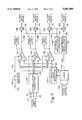
- FIG. 1 is block diagram of a Holter recorder and playback unit.
- FIG. 2 is a block diagram of data formatter 46 shown in FIG. 1 implemented as an integrated circuit.
- FIG. 3 is a detailed block diagram of the Holter recorder shown in FIG. 1.
- FIG. 4 is a detailed schematic of an individual pre-emphasis amplifier contained in the recorder of FIG. 1.
- a Holter recorder and playback unit is shown generally at 10.
- the system comprises a portable Holter recorder 12 for recording ECG patient signals received over patient monitor lines 14, 16, and 18, which are typically connected to patch-type electrodes affixed to the patient's skin. A different ECG signal is provided on each of the three lines.
- Recorder 12 is desirably a miniature recorder worn on the patient's belt in order to collect data over an extended period of time.
- the portable Holter recorder 12 also includes means for generating and recording a repetitive characterization signal (not shown in FIG. 1 and explained in greater detail below).
- the ECG patient signals and characterization signal are processed within recorder 12 to produce recorder signals 20 capable of being stored on a standard magnetic cassette tape 22 held in the recorder 12.
- Each of the three ECG signals is recorded onto separate tracks of the magnetic cassette tape 22, e.g., tracks 1, 2 and 4.
- a characterization signal may also be recorded on the tape tracks prior to recording the ECG signals.
- a timing signal is recorded onto yet another separate, track 3.
- the timing signal is a constant frequency signal which creates timing information on tape 22.
- a patient activated signal created by depressing a switch, can be captured on the timing track.
- EGG signals are recorded on tape 22, it is removed from recorder 12 and installed in a playback transport system 25.
- Each of the four recorded tracks are played back by playback unit 25 which includes a playback transport and post processing circuitry, as well as computer control interface and testing outputs.
- a playback head 26 converts the information stored on each of the four tracks on magnetic tape 22 into four separate analog playback signals which are applied to analog track lines 28. Each track line corresponds to one of four separate tracks on the tape 22.
- the circuitry contained in each of blocks 30, 34, 38, and 42, described below, is replicated for each track although separate blocks for each channel are not shown in FIG. 1 to simplify the drawing. Although the preferred embodiment shown in FIG. 1 uses a four track tape, any reasonable number of tracks and patient inputs can be used.
- the analog track lines 28 are connected to playback amplifiers 30.
- the playback amplifiers 30 amplify the analog recorded signals on analog track lines 28 to produce amplified analog signals on amplifier output lines 32.
- the amplifier output lines 32 are connected to anti-alias filters 34 which act essentially as low pass filters having a corner frequency of about 200 kHz.
- the anti-alias filters 34 are implemented using conventional R-C networks.
- the filtered analog signals produced by the anti-alias filters 34 are coupled to analog-to-digital converters ("ADCs") 38 over filter output lines 36 connected between the anti-alias filters 34 and ADCs 38.
- Analog-to-digital converters 38 also have anti-alias filters with a comer frequency of about 50 kHz.
- the analog signals received by ADCs 38 are converted into a digital representation for subsequent digital processing by digital signal processors ("DSP") 42.
- DSP digital signal processors
- each of the analog-to-digital converters is a 56ADC16 manufactured by Motorola of Phoenix, Ariz.
- the ADCs 38 produce digital outputs on busses 40 which are connected to digital signal processors 42.
- Each of the digital outputs is a 16-bit sample value which is applied to bus 40 at a rate of 100,000 samples/second.
- the digital signal processors 42 includes a separate signal processor dedicated to each track.
- Each of the digital signal processors in the preferred embodiment, is a 56002 DSP also manufactured by Motorola.
- the digital signal processors perform the necessary digital processing, as is hereinafter explained, of the digital output, as required by the invention, to produce processed digital data on DSP bi-directional output busses 44.
- Data formatter 46 is coupled between DSP 42 and digital-to-analog-converters ("DACs") 49.
- the DSP bidirectional output busses 44 of the DSP 42 are connected to data formatter 46.
- Data formatter 46 is connected to DACs 49 through two serial data lines 48. Two of the processed digital outputs 44 are multiplexed onto each of the serial data lines 48 by data formatter 46.
- the serial data lines 48 are coupled to DACs 49 which produce analog outputs 50, 52, 54, and 56.
- the analog outputs 50, 52, 54, and 56 can be used as test points or for other purposes.
- DACs 49 are multiplexing "dual DACs", C54328 manufactured by Crystal Semiconductor of Austin, Tex.
- the data formatter 46 also operates as a gateway between a SCSI (small computer systems interface) port 62 and DSP 42.
- Data formatter 46 operates under the control of an I/O processor 70.
- the data formatter 46 is connected to the I/O processor 70 through an I/O bus 60.
- I/O processor 70 is further connected to a SCSI port 62 through SCSI control bus 68 and to capstan motor control 74 through capstan control bus 72.
- I/O processor 70 configures data formatter 46 in response to commands sent or received through SCSI port 62.
- the commands comply with the industry standard SCSI protocol, which governs transfers across SCSI data bus 64 connected between SCSI port 62 and PC controller 66.
- the commands specify the transfer attributes including: the type of transfer, i.e., read or write; the source and destination addresses; and the corresponding number of bytes.
- the I/O processor 70 configures data formatter 46, by writing to registers within data formatter 46, in order to accomplish the transfer specified by the command.
- SCSI port 62 is coupled to PC controller 66 across SCSI bus 64.
- PC controller 66 is able to receive processed digital data from DSP 42 across SCSI bus 64 as well as send configuration information to DSP 42 across SCSI bus 64.
- the PC controller 66 can perform further processing, if necessary, on the processed digital data and display, print or store the resulting output.
- the PC controller 66 also receives the characterization signal.
- the characterization signal received in the processed digital data is examined by the PC controller to determine the compensation required by DSP 42.
- the PC controller 66 transmits filter coefficients via SCSI bus 64 to DSP 42 in order to accomplish the required compensation, as is described in greater detail below.
- Digital signal processing can be allocated between DSP 42 and the PC controller 66.
- formatter 46 is implemented as an integrated circuit ("IC") gate array.
- Processed digital outputs 44 are comprised of four separate bidirectional busses 76, 78, 80, and 82, one for each digital signal processor.
- the bidirectional busses 76, 78, 80, and 82 connect to a corresponding set of DSP interface registers 84, one set connected to each bidirectional bus.
- each DSP 42 in FIG. 1, interfaces with a set of read/write registers used to transfer data to and from a buffer ram 126, the other three DSP's and a DAC formatter 92. Additionally, some registers are used for control functions.
- Each register set is connected to DAC formatter 92 through a corresponding DAC interface bus 84, 86, 88, and 90.
- the DAC interface busses pass the processed digital data from the respective digital signal processor to the DAC formatter 92.
- the DAC formatter 92 interleaves and serializes the processed digital data received from two DAC interface busses onto a single serial data line, either 94 or 96, with the other two DAC interface busses being output in a similar manner on the remaining serial data line.
- the DAC formatter 92 receives a clock signal 108 from DAC clock generator 104, which clocks out serial data output on the serial data lines 94 and 96.
- I/O processor (IOP) interface 122 interfaces the data formatter to the I/O processor (not shown in FIG. 2) through IOP bus 60.
- the IOP interface 122 directs the data present on IOP bus 60 to the appropriate destination.
- the IOP interface 122 can direct the data on IOP bus 60 to DAC clock generator 104 over bus 100, or to ADC clock generator 106 over bus 102.
- I/O processor 70 in FIG. 1 can write data to DAC clock generator 104 to establish the necessary clock frequency on DAC clock 108 and, similarly, can write data to ADC clock generator 106 to establish the necessary clock frequency on ADC clock 110.
- IOP interface 122 also interfaces to a buffer RAM controller 116 over bidirectional buffer RAM controller bus 118. IOP interface 122 can send or receive data from the buffer RAM controller 116 over bidirectional buffer RAM controller bus 118.
- 10P interface 122 also provides reset line 120 connected to ADC/DAC reset controller 112, which, in turn, produces reset output 114.
- Buffer RAM controller 116 is connected to all four sets of buffer RAM registers in DSP interface registers 84 via bus 98. Buffer RAM controller 116 is also connected to buffer RAM 126 through RAM controller bus 125. Communication between the DSP interface registers 84 and buffer RAM 126 and between the IOP interface 122 and buffer RAM 126 is controlled by buffer RAM controller 116. The buffer RAM controller 116 is responsible for sequentially polling the DSP and IOP interface registers and transferring any data found thereby to RAM buffer 126. Also, the buffer RAM controller 116 receives data from the buffer RAM 126 and transfers the data to the appropriate DSP interface register. In addition, the buffer RAM controller coordinates transfers of data to and from IOP interface 122. Buffer RAM 126 is connected directly to SCSI port through RAM bus 58.
- buffer RAM 126 is a 32K ⁇ 16 dual ported bidirectional first-in-first-out (FIFO) RAM, which can be included as part of the data formatter 46 IC or as a stand-alone IC such as ⁇ PD42532 manufactured by NEC of Mountain View, Calif.
- FIFO first-in-first-out
- FIG. 3 recorder 12 of FIG. 1 is shown in greater detail.
- the patient signals 14, 16, and 18, which are each differential inputs, are received by a defibrillator protection network 134, which provides protection for both the recorder and the patient in the event of a patient being defibrillated while connected to the recorder.
- the outputs 136 consist of three differential signal pairs from network 134.
- Each pre-emphasis amplifier 138, 140, and 142 receives a gain setting signal on line 132 from ECG gain switch 130.
- the gain switch 130 allows the gain of each amplifier to be individually set to one of two present values.
- Pre-emphasis amplifiers 138, 140, and 142 also receive calibration and characterization signals over output lines 145 from a calibration pulse generator 144.
- the calibration pulse generator is connected to a logic circuit 146 through input lines 148. Control signals are transmitted on input lines 148 during a characterization/calibration period.
- Calibration pulse generator 144 transmits characterization and calibration signals on output lines 145 for approximately the first 8 1/2 minutes after the recorder power is turned on.
- Patient event button 150 is connected to logic circuit 146. Event button 150 is pressed by the patient during a physical event that the patient wishes to note. When event button 150 is pressed, logic circuit 146 amplitude-modulates timing track oscillator 154 with control signal 152. The amplitude modulation of oscillator 154 is used to indicate a patient event on the timing track.
- Pre-emphasis amplifiers 138, 140, and 142 have single-ended outputs 178, 180, and 182, respectively, which are connected to summers 164, 166, and 168, respectively, as well as being supplied as output test channels.
- the single-ended outputs 178, 180, and 182 are combined with an AC-bias signal on bias line 160 produced by an AC-bias oscillator 158.
- the AC-bias signal is required in head output lines 172, 174, and 176 in order for the head output signals to be properly recorded by the tape head.
- oscillator output 156 is combined with AC-bias signal 160 by summer 162 to produce head output line 170.
- Summers 162, 164, 166, and 168 are implemented with passive networks, described in detail below.
- the pre-emphasis amplifier is comprised of three separate stages: a differential amplifier 192 having a predetermined high frequency rolloff, a differential input (VIN+ and VIN-) and a differential output (198 and 200); a differential-to-single-ended converter 194 having a differential input coupled to the output of the differential amplifier and an output 202; and an output amplifier 196 having a predetermined high frequency boost, an input coupled to the output of the differential-to-single-ended converter, and an output for providing a single-ended boosted voltage.
- the differential amplifier stage 192 receives a differential input signal consisting of a positive input VIN+ and a negative input VIN-.
- the differential amplifier stage 192 has a first operational amplifier (“op-amp") 184 and a second operational amplifier 186 coupled to the negative input VIN+ and the positive input VIN+, respectively.
- the negative input VIN- is connected to the positive input of the first op-amp 184.
- Coupled between the negative input and the output of the first op-amp 184 is a first feedback network, consisting of a parallel combination of resistor R3 and capacitor C1.
- the positive input of the second op-amp 186 is connected to the positive input VIN+.
- Coupled between the negative input and the output of the second operational amplifier 186 is a second feedback network, consisting of the parallel combination of resistor R4 and capacitor C2.
- resistors R3 and R4 are about 4.64 K ⁇ and capacitors C1 and C2 are about 0.1 ⁇ F to produce a rolloff frequency of about 300 hertz.
- the output 198 of the first op-amp 184 and the output of the second op-amp 186 form the differential output of differential output stage 192.
- Coupled between the negative inputs of the first and second op-amps 184 and 186 is a third network comprising a first resistor R2; a second resistor R 1; and a switch S1A for coupling either the first resistor, or the parallel combination of the first and second resistors, to the negative inputs of the first and second op-amps.
- first resistor R2 is about 2.15 K ⁇ and second resistor R1 is about 1.78 K ⁇ .
- switch S1A When switch S1A is open, the first resistor R2 is coupled between the negative inputs of first 184 and second 186 op-amps.
- the gain of the differential input stage 192 can be set to two distinct settings by opening or closing the switch S1A. In the preferred embodiment, using the values indicated above, the gain of the differential input stage is reduced by about one-half when switch S1A is open.
- the differential output 198, 200 of differential input stage 192 is coupled to a differential-to-single-ended converter 194.
- the differential-to-single-ended converter 194 includes an op-amp 188 and four gain-setting resistors.
- the first differential output 198 is coupled to the negative input of op-amp 188 through a first resistor R5.
- a second resistor R6 is coupled between the negative input and the output of op-amp 188.
- the second differential output 200 is coupled to the positive input of op-amp 188 through a third resistor R7.
- a fourth resistor R8 is coupled between the positive input of op-amp 188 and ground.
- the first, second, third, and fourth resistors are about 10K ⁇ , and the overall gain of converter 194 is unity.
- the single-ended output 202 is AC-coupled to output amplifier 196 through high-pass resistor-capacitor network including resistor R9 and capacitor C3.
- Coupling capacitor C3 is coupled between single-ended output 202 and output amplifier 196 input 204.
- Resistor R9 is coupled between the input of output amplifier 196 and ground.
- coupling capacitor C3 is comprised of four parallel 1 ⁇ F capacitors, and resistor R9 is about 825 K ⁇ .
- Output amplifier 196 is comprised of an operational amplifier 190 having a positive input forming the input to the output amplifier, a negative input, and an output forming the output of the output amplifier V OUT .
- a capacitor C10 and a resistor R10 are coupled to the negative input of op-amp 190 and to a node 206.
- the parallel combination of resistor R13 and a capacitor C7 is coupled between the output of op-amp 190 and node 206.
- Coupled between node 206 and node 208 is resistor R11, and coupled between node 208 and ground is the parallel combination of resistor R12 and R14 in a first leg, capacitance C8 in a second leg, and capacitance C9 in a third leg.
- resistor R12 is about 9.09 K ⁇
- R14 is about 422 ⁇
- capacitance C8 is about 0.68 ⁇ F
- capacitance C9 is about 0.47 ⁇ F producing a rolloff frequency of about 30 hertz. This results in a greater gain at the higher frequencies than the lower frequencies, referred to herein as pre-emphasis.
- a pole is introduced by the parallel combination of resistor R13 and capacitance C7, leveling out the frequency response at the corresponding rolloff frequency.
- resistor R13 is about equal to 196 K ⁇ and capacitance C7 is about 4700 pF, producing a rolloff frequency of about 170 Hz.
- the overall gain of the amplifier increases gradually above 10 hertz to a peak of about 10 dB of gain at about 150 hertz. If pre-emphasis is not desired, capacitors C8 and C9 can be removed from the circuit.
Abstract
Description
Claims (5)
Priority Applications (1)
| Application Number | Priority Date | Filing Date | Title |
|---|---|---|---|
| US08/379,046 US5601089A (en) | 1993-03-12 | 1995-01-26 | Method and apparatus for boosting the amplitude of ECG signals within a predetermined frequency range |
Applications Claiming Priority (2)
| Application Number | Priority Date | Filing Date | Title |
|---|---|---|---|
| US08/031,437 US5406955A (en) | 1993-03-12 | 1993-03-12 | ECG recorder and playback unit |
| US08/379,046 US5601089A (en) | 1993-03-12 | 1995-01-26 | Method and apparatus for boosting the amplitude of ECG signals within a predetermined frequency range |
Related Parent Applications (1)
| Application Number | Title | Priority Date | Filing Date |
|---|---|---|---|
| US08/031,437 Division US5406955A (en) | 1993-03-12 | 1993-03-12 | ECG recorder and playback unit |
Publications (1)
| Publication Number | Publication Date |
|---|---|
| US5601089A true US5601089A (en) | 1997-02-11 |
Family
ID=21859454
Family Applications (3)
| Application Number | Title | Priority Date | Filing Date |
|---|---|---|---|
| US08/031,437 Expired - Fee Related US5406955A (en) | 1993-03-12 | 1993-03-12 | ECG recorder and playback unit |
| US08/378,338 Expired - Fee Related US5553623A (en) | 1993-03-12 | 1995-01-26 | Method for calibrating a system for recording and playing back ECG signals |
| US08/379,046 Expired - Fee Related US5601089A (en) | 1993-03-12 | 1995-01-26 | Method and apparatus for boosting the amplitude of ECG signals within a predetermined frequency range |
Family Applications Before (2)
| Application Number | Title | Priority Date | Filing Date |
|---|---|---|---|
| US08/031,437 Expired - Fee Related US5406955A (en) | 1993-03-12 | 1993-03-12 | ECG recorder and playback unit |
| US08/378,338 Expired - Fee Related US5553623A (en) | 1993-03-12 | 1995-01-26 | Method for calibrating a system for recording and playing back ECG signals |
Country Status (1)
| Country | Link |
|---|---|
| US (3) | US5406955A (en) |
Cited By (43)
| Publication number | Priority date | Publication date | Assignee | Title |
|---|---|---|---|---|
| US6249696B1 (en) | 1999-01-15 | 2001-06-19 | Medtronic Physio-Control Manufacturing Corp. | Method and apparatus for increasing the low frequency dynamic range of a digital ECG measuring system |
| US6280391B1 (en) | 1999-02-08 | 2001-08-28 | Physio-Control Manufacturing Corporation | Method and apparatus for removing baseline wander from an egg signal |
| US20060015033A1 (en) * | 2004-07-19 | 2006-01-19 | Blakley Daniel R | ECG electrode characterization and compensation |
| WO2016044477A1 (en) * | 2014-09-16 | 2016-03-24 | Bardy Diagnostics, Inc. | Ambulatory electrocardiography monitor recorder |
| US9364155B2 (en) | 2013-09-25 | 2016-06-14 | Bardy Diagnostics, Inc. | Self-contained personal air flow sensing monitor |
| US9408545B2 (en) | 2013-09-25 | 2016-08-09 | Bardy Diagnostics, Inc. | Method for efficiently encoding and compressing ECG data optimized for use in an ambulatory ECG monitor |
| US9408551B2 (en) | 2013-11-14 | 2016-08-09 | Bardy Diagnostics, Inc. | System and method for facilitating diagnosis of cardiac rhythm disorders with the aid of a digital computer |
| US9433380B1 (en) | 2013-09-25 | 2016-09-06 | Bardy Diagnostics, Inc. | Extended wear electrocardiography patch |
| US9433367B2 (en) | 2013-09-25 | 2016-09-06 | Bardy Diagnostics, Inc. | Remote interfacing of extended wear electrocardiography and physiological sensor monitor |
| US9504423B1 (en) | 2015-10-05 | 2016-11-29 | Bardy Diagnostics, Inc. | Method for addressing medical conditions through a wearable health monitor with the aid of a digital computer |
| US9545204B2 (en) | 2013-09-25 | 2017-01-17 | Bardy Diagnostics, Inc. | Extended wear electrocardiography patch |
| US9554715B2 (en) | 2013-09-25 | 2017-01-31 | Bardy Diagnostics, Inc. | System and method for electrocardiographic data signal gain determination with the aid of a digital computer |
| US9619660B1 (en) | 2013-09-25 | 2017-04-11 | Bardy Diagnostics, Inc. | Computer-implemented system for secure physiological data collection and processing |
| US9615763B2 (en) | 2013-09-25 | 2017-04-11 | Bardy Diagnostics, Inc. | Ambulatory electrocardiography monitor recorder optimized for capturing low amplitude cardiac action potential propagation |
| US9655537B2 (en) | 2013-09-25 | 2017-05-23 | Bardy Diagnostics, Inc. | Wearable electrocardiography and physiology monitoring ensemble |
| US9655538B2 (en) | 2013-09-25 | 2017-05-23 | Bardy Diagnostics, Inc. | Self-authenticating electrocardiography monitoring circuit |
| US9700227B2 (en) | 2013-09-25 | 2017-07-11 | Bardy Diagnostics, Inc. | Ambulatory electrocardiography monitoring patch optimized for capturing low amplitude cardiac action potential propagation |
| US9717432B2 (en) | 2013-09-25 | 2017-08-01 | Bardy Diagnostics, Inc. | Extended wear electrocardiography patch using interlaced wire electrodes |
| US9717433B2 (en) | 2013-09-25 | 2017-08-01 | Bardy Diagnostics, Inc. | Ambulatory electrocardiography monitoring patch optimized for capturing low amplitude cardiac action potential propagation |
| US9737224B2 (en) | 2013-09-25 | 2017-08-22 | Bardy Diagnostics, Inc. | Event alerting through actigraphy embedded within electrocardiographic data |
| US9775536B2 (en) | 2013-09-25 | 2017-10-03 | Bardy Diagnostics, Inc. | Method for constructing a stress-pliant physiological electrode assembly |
| CN108135519A (en) * | 2015-08-18 | 2018-06-08 | 路易斯维尔大学研究基金会公司 | Lock-out pulse detector |
| US10165946B2 (en) | 2013-09-25 | 2019-01-01 | Bardy Diagnostics, Inc. | Computer-implemented system and method for providing a personal mobile device-triggered medical intervention |
| US10251576B2 (en) | 2013-09-25 | 2019-04-09 | Bardy Diagnostics, Inc. | System and method for ECG data classification for use in facilitating diagnosis of cardiac rhythm disorders with the aid of a digital computer |
| US10433751B2 (en) | 2013-09-25 | 2019-10-08 | Bardy Diagnostics, Inc. | System and method for facilitating a cardiac rhythm disorder diagnosis based on subcutaneous cardiac monitoring data |
| US10433748B2 (en) | 2013-09-25 | 2019-10-08 | Bardy Diagnostics, Inc. | Extended wear electrocardiography and physiological sensor monitor |
| US10463269B2 (en) | 2013-09-25 | 2019-11-05 | Bardy Diagnostics, Inc. | System and method for machine-learning-based atrial fibrillation detection |
| US10624551B2 (en) | 2013-09-25 | 2020-04-21 | Bardy Diagnostics, Inc. | Insertable cardiac monitor for use in performing long term electrocardiographic monitoring |
| US10667711B1 (en) | 2013-09-25 | 2020-06-02 | Bardy Diagnostics, Inc. | Contact-activated extended wear electrocardiography and physiological sensor monitor recorder |
| RU2728869C1 (en) * | 2019-08-30 | 2020-07-31 | Закрытое Акционерное Общество "Ес-Лизинг" | Computerized method for non-invasive detection of carbohydrate metabolism disorders by electrocardiogram |
| US10736529B2 (en) | 2013-09-25 | 2020-08-11 | Bardy Diagnostics, Inc. | Subcutaneous insertable electrocardiography monitor |
| US10736531B2 (en) | 2013-09-25 | 2020-08-11 | Bardy Diagnostics, Inc. | Subcutaneous insertable cardiac monitor optimized for long term, low amplitude electrocardiographic data collection |
| US10799137B2 (en) | 2013-09-25 | 2020-10-13 | Bardy Diagnostics, Inc. | System and method for facilitating a cardiac rhythm disorder diagnosis with the aid of a digital computer |
| US10806360B2 (en) | 2013-09-25 | 2020-10-20 | Bardy Diagnostics, Inc. | Extended wear ambulatory electrocardiography and physiological sensor monitor |
| US10820801B2 (en) | 2013-09-25 | 2020-11-03 | Bardy Diagnostics, Inc. | Electrocardiography monitor configured for self-optimizing ECG data compression |
| US10888239B2 (en) | 2013-09-25 | 2021-01-12 | Bardy Diagnostics, Inc. | Remote interfacing electrocardiography patch |
| US11096579B2 (en) | 2019-07-03 | 2021-08-24 | Bardy Diagnostics, Inc. | System and method for remote ECG data streaming in real-time |
| US11116451B2 (en) | 2019-07-03 | 2021-09-14 | Bardy Diagnostics, Inc. | Subcutaneous P-wave centric insertable cardiac monitor with energy harvesting capabilities |
| US11213237B2 (en) | 2013-09-25 | 2022-01-04 | Bardy Diagnostics, Inc. | System and method for secure cloud-based physiological data processing and delivery |
| US11324441B2 (en) | 2013-09-25 | 2022-05-10 | Bardy Diagnostics, Inc. | Electrocardiography and respiratory monitor |
| US11678830B2 (en) | 2017-12-05 | 2023-06-20 | Bardy Diagnostics, Inc. | Noise-separating cardiac monitor |
| US11696681B2 (en) | 2019-07-03 | 2023-07-11 | Bardy Diagnostics Inc. | Configurable hardware platform for physiological monitoring of a living body |
| US11723575B2 (en) | 2013-09-25 | 2023-08-15 | Bardy Diagnostics, Inc. | Electrocardiography patch |
Families Citing this family (29)
| Publication number | Priority date | Publication date | Assignee | Title |
|---|---|---|---|---|
| SE9302432D0 (en) * | 1993-07-16 | 1993-07-16 | Siemens-Elema Ab | DEVICE FOR FILTERING ECG SIGNALS |
| US5627859A (en) * | 1994-07-11 | 1997-05-06 | Huges Electronics | Time-reversed infinite impulse response digital filtering |
| US5467774A (en) * | 1994-06-15 | 1995-11-21 | Hewlett-Packard Corporation | Method and system for precise time based presentation of recorded medical data |
| US5685316A (en) * | 1996-04-08 | 1997-11-11 | Rheo-Graphic Pte Ltd. | Non-invasive monitoring of hemodynamic parameters using impedance cardiography |
| US6002952A (en) | 1997-04-14 | 1999-12-14 | Masimo Corporation | Signal processing apparatus and method |
| EP0957635B1 (en) * | 1998-05-15 | 2009-10-07 | Nxp B.V. | Filtering circuit |
| US8438038B2 (en) * | 1999-04-16 | 2013-05-07 | Cardiocom, Llc | Weight loss or weight management system |
| US7945451B2 (en) * | 1999-04-16 | 2011-05-17 | Cardiocom, Llc | Remote monitoring system for ambulatory patients |
| US8419650B2 (en) * | 1999-04-16 | 2013-04-16 | Cariocom, LLC | Downloadable datasets for a patient monitoring system |
| US7577475B2 (en) * | 1999-04-16 | 2009-08-18 | Cardiocom | System, method, and apparatus for combining information from an implanted device with information from a patient monitoring apparatus |
| US20070021979A1 (en) * | 1999-04-16 | 2007-01-25 | Cosentino Daniel L | Multiuser wellness parameter monitoring system |
| US20060030890A1 (en) * | 1999-04-16 | 2006-02-09 | Cosentino Daniel L | System, method, and apparatus for automated interactive verification of an alert generated by a patient monitoring device |
| US6290646B1 (en) | 1999-04-16 | 2001-09-18 | Cardiocom | Apparatus and method for monitoring and communicating wellness parameters of ambulatory patients |
| US6370432B1 (en) * | 1999-08-20 | 2002-04-09 | Cardiac Pacemakers, Inc. | Pacemaker passive measurement testing system and method |
| US6454705B1 (en) | 1999-09-21 | 2002-09-24 | Cardiocom | Medical wellness parameters management system, apparatus and method |
| SE515642C2 (en) * | 2000-01-19 | 2001-09-17 | Saab Dynamics Ab | Method and apparatus for signal processing by means of a Discrete Fourier transform with limited word length |
| US20040193033A1 (en) * | 2002-10-04 | 2004-09-30 | Badehi Avner Pierre | Noninvasive methods and apparatuses for measuring the intraocular pressure of a mammal eye |
| US7177108B2 (en) * | 2003-06-03 | 2007-02-13 | Quantum Corporation | Emulation of auxiliary memory |
| US7277246B2 (en) * | 2003-07-18 | 2007-10-02 | Quantum Corporation | Methods and systems for providing predictive maintenance, preventative maintenance, and/or failure isolation in a tape storage subsystem |
| US20050192487A1 (en) * | 2004-02-27 | 2005-09-01 | Cosentino Louis C. | System for collection, manipulation, and analysis of data from remote health care devices |
| US7443927B2 (en) * | 2004-03-15 | 2008-10-28 | Asia Optical Co., Inc. | Signal detector |
| US20070073590A1 (en) * | 2005-08-22 | 2007-03-29 | Cosentino Louis C | Remote monitor for physiological parameters and durable medical supplies |
| US20070136517A1 (en) * | 2005-11-29 | 2007-06-14 | Quantum Corporation | Use of directory revision number to validate directory |
| US9591981B2 (en) * | 2012-12-04 | 2017-03-14 | Biosense Webster (Isreal) Ltd. | Multi-channel ECG measurement |
| US9395234B2 (en) | 2012-12-05 | 2016-07-19 | Cardiocom, Llc | Stabilizing base for scale |
| CN107296599B (en) * | 2017-05-16 | 2024-01-26 | 武汉思创电子有限公司 | Multi-lead ECG signal conditioning and data acquisition circuit |
| DE102019216780A1 (en) * | 2019-10-30 | 2021-05-06 | Neuroloop GmbH | Device and method for the detection of a medical active implant located within an individual |
| RU2723222C1 (en) * | 2019-11-18 | 2020-06-09 | Евгений Владимирович Круглов | Electric cardiosignal processing unit with analogue-digital filtration |
| CN114469125B (en) * | 2022-02-17 | 2024-04-05 | 浙江荣泰健康电器有限公司 | Electrocardiogram calibration system, method, equipment and storage medium |
Citations (20)
| Publication number | Priority date | Publication date | Assignee | Title |
|---|---|---|---|---|
| US3721230A (en) * | 1970-11-23 | 1973-03-20 | Overton M Iii | High-gain monitor to determine electro-cerebral silence |
| US3871363A (en) * | 1973-12-19 | 1975-03-18 | American Optical Corp | Pacer diagnostic instrument |
| US4098267A (en) * | 1977-07-05 | 1978-07-04 | Clinical Data, Inc. | System for display and analysis of physiological signals such as electrocardiographic (ECG) signals |
| US4291703A (en) * | 1978-11-01 | 1981-09-29 | Del Mar Avionics | Pacemaker monitoring recorder |
| US4333475A (en) * | 1979-12-06 | 1982-06-08 | Medical Concepts, Inc. | Ambulatory cardiac monitoring system |
| US4422459A (en) * | 1980-11-18 | 1983-12-27 | University Patents, Inc. | Electrocardiographic means and method for detecting potential ventricular tachycardia |
| US4457315A (en) * | 1978-09-18 | 1984-07-03 | Arvin Bennish | Cardiac arrhythmia detection and recording |
| US4494551A (en) * | 1982-11-12 | 1985-01-22 | Medicomp, Inc. | Alterable frequency response electrocardiographic amplifier |
| US4532934A (en) * | 1978-11-01 | 1985-08-06 | Del Mar Avionics | Pacemaker monitoring recorder and malfunction analyzer |
| US4580576A (en) * | 1983-01-20 | 1986-04-08 | Chiltern International Limited | ECG recorder |
| US4585201A (en) * | 1984-07-23 | 1986-04-29 | Pursell Richard A | Christmas tree stand |
| US4624263A (en) * | 1983-08-25 | 1986-11-25 | Advanced Medical Electronics Developments Limited Partnership | Portable electrocardiograph with digitally-printing waveform display |
| US4630204A (en) * | 1984-02-21 | 1986-12-16 | Mortara Instrument Inc. | High resolution ECG waveform processor |
| US4680708A (en) * | 1984-03-20 | 1987-07-14 | Washington University | Method and apparatus for analyzing electrocardiographic signals |
| US4696306A (en) * | 1985-11-20 | 1987-09-29 | Akai Electric Co., Ltd. | Electrocardiogram playback system and method |
| US4721114A (en) * | 1986-02-21 | 1988-01-26 | Cardiac Pacemakers, Inc. | Method of detecting P-waves in ECG recordings |
| US4883065A (en) * | 1988-11-15 | 1989-11-28 | Del Mar Avionics | Micropotential analyzer--a Holter system with comprehensive analysis capability for very low amplitude electrocardiographic signals and method |
| US4961428A (en) * | 1988-05-02 | 1990-10-09 | Northeastern University | Non-invasive method and apparatus for describing the electrical activity of the surface of an interior organ |
| US5030911A (en) * | 1980-10-19 | 1991-07-09 | Baker Hughes Incorporated | Method and apparatus for displaying defects in tubular members on a two-dimensional map in a variety of display modes |
| US5050021A (en) * | 1990-03-16 | 1991-09-17 | Del Mar Avionics | Expanded micro cassette player-recorder |
Family Cites Families (1)
| Publication number | Priority date | Publication date | Assignee | Title |
|---|---|---|---|---|
| IL67660A (en) * | 1983-01-11 | 1987-07-31 | Fidelity Medical Ltd | Signal processing apparatus and high resolution electrocardiograph equipment including same |
-
1993
- 1993-03-12 US US08/031,437 patent/US5406955A/en not_active Expired - Fee Related
-
1995
- 1995-01-26 US US08/378,338 patent/US5553623A/en not_active Expired - Fee Related
- 1995-01-26 US US08/379,046 patent/US5601089A/en not_active Expired - Fee Related
Patent Citations (20)
| Publication number | Priority date | Publication date | Assignee | Title |
|---|---|---|---|---|
| US3721230A (en) * | 1970-11-23 | 1973-03-20 | Overton M Iii | High-gain monitor to determine electro-cerebral silence |
| US3871363A (en) * | 1973-12-19 | 1975-03-18 | American Optical Corp | Pacer diagnostic instrument |
| US4098267A (en) * | 1977-07-05 | 1978-07-04 | Clinical Data, Inc. | System for display and analysis of physiological signals such as electrocardiographic (ECG) signals |
| US4457315A (en) * | 1978-09-18 | 1984-07-03 | Arvin Bennish | Cardiac arrhythmia detection and recording |
| US4291703A (en) * | 1978-11-01 | 1981-09-29 | Del Mar Avionics | Pacemaker monitoring recorder |
| US4532934A (en) * | 1978-11-01 | 1985-08-06 | Del Mar Avionics | Pacemaker monitoring recorder and malfunction analyzer |
| US4333475A (en) * | 1979-12-06 | 1982-06-08 | Medical Concepts, Inc. | Ambulatory cardiac monitoring system |
| US5030911A (en) * | 1980-10-19 | 1991-07-09 | Baker Hughes Incorporated | Method and apparatus for displaying defects in tubular members on a two-dimensional map in a variety of display modes |
| US4422459A (en) * | 1980-11-18 | 1983-12-27 | University Patents, Inc. | Electrocardiographic means and method for detecting potential ventricular tachycardia |
| US4494551A (en) * | 1982-11-12 | 1985-01-22 | Medicomp, Inc. | Alterable frequency response electrocardiographic amplifier |
| US4580576A (en) * | 1983-01-20 | 1986-04-08 | Chiltern International Limited | ECG recorder |
| US4624263A (en) * | 1983-08-25 | 1986-11-25 | Advanced Medical Electronics Developments Limited Partnership | Portable electrocardiograph with digitally-printing waveform display |
| US4630204A (en) * | 1984-02-21 | 1986-12-16 | Mortara Instrument Inc. | High resolution ECG waveform processor |
| US4680708A (en) * | 1984-03-20 | 1987-07-14 | Washington University | Method and apparatus for analyzing electrocardiographic signals |
| US4585201A (en) * | 1984-07-23 | 1986-04-29 | Pursell Richard A | Christmas tree stand |
| US4696306A (en) * | 1985-11-20 | 1987-09-29 | Akai Electric Co., Ltd. | Electrocardiogram playback system and method |
| US4721114A (en) * | 1986-02-21 | 1988-01-26 | Cardiac Pacemakers, Inc. | Method of detecting P-waves in ECG recordings |
| US4961428A (en) * | 1988-05-02 | 1990-10-09 | Northeastern University | Non-invasive method and apparatus for describing the electrical activity of the surface of an interior organ |
| US4883065A (en) * | 1988-11-15 | 1989-11-28 | Del Mar Avionics | Micropotential analyzer--a Holter system with comprehensive analysis capability for very low amplitude electrocardiographic signals and method |
| US5050021A (en) * | 1990-03-16 | 1991-09-17 | Del Mar Avionics | Expanded micro cassette player-recorder |
Non-Patent Citations (10)
| Title |
|---|
| "The Recording Studio Handbook", John M. Woram, Sagamore Publishing Company, Inc., Apr., 1980, pp. 327-331. |
| Jorgensen, The Complete Handbook of Magnetic Recording (3rd Edition) 1998, pp. 492 497. * |
| Jorgensen, The Complete Handbook of Magnetic Recording (3rd Edition) 1998, pp. 492-497. |
| Mazade et al, "Medical & Biological Engineering & Computing" vol. 17, 1979, pp. 683-687, copy in 128/711. |
| Mazade et al, Medical & Biological Engineering & Computing vol. 17, 1979, pp. 683 687, copy in 128/711. * |
| Oppenheim, Digital Signal Processing, 1975, p. 19. * |
| Service Manual For Holter Acquisition Module, "Preliminary", Marquette Electronics Inc., Jun. 15, 1993, pp. 9-11. |
| Service Manual For Holter Acquisition Module, Preliminary , Marquette Electronics Inc., Jun. 15, 1993, pp. 9 11. * |
| The Recording Studio Handbook , John M. Woram, Sagamore Publishing Company, Inc., Apr., 1980, pp. 327 331. * |
| Woram, The Recording Studio Handbook, 1980, p. 279. * |
Cited By (125)
| Publication number | Priority date | Publication date | Assignee | Title |
|---|---|---|---|---|
| US6249696B1 (en) | 1999-01-15 | 2001-06-19 | Medtronic Physio-Control Manufacturing Corp. | Method and apparatus for increasing the low frequency dynamic range of a digital ECG measuring system |
| US6280391B1 (en) | 1999-02-08 | 2001-08-28 | Physio-Control Manufacturing Corporation | Method and apparatus for removing baseline wander from an egg signal |
| US20060015033A1 (en) * | 2004-07-19 | 2006-01-19 | Blakley Daniel R | ECG electrode characterization and compensation |
| US7245961B2 (en) | 2004-07-19 | 2007-07-17 | Hewlett-Packard Development Company, L.P. | ECG electrode characterization and compensation |
| US10561328B2 (en) | 2013-09-25 | 2020-02-18 | Bardy Diagnostics, Inc. | Multipart electrocardiography monitor optimized for capturing low amplitude cardiac action potential propagation |
| US10413205B2 (en) | 2013-09-25 | 2019-09-17 | Bardy Diagnostics, Inc. | Electrocardiography and actigraphy monitoring system |
| US9408545B2 (en) | 2013-09-25 | 2016-08-09 | Bardy Diagnostics, Inc. | Method for efficiently encoding and compressing ECG data optimized for use in an ambulatory ECG monitor |
| US11918364B2 (en) | 2013-09-25 | 2024-03-05 | Bardy Diagnostics, Inc. | Extended wear ambulatory electrocardiography and physiological sensor monitor |
| US9433380B1 (en) | 2013-09-25 | 2016-09-06 | Bardy Diagnostics, Inc. | Extended wear electrocardiography patch |
| US9433367B2 (en) | 2013-09-25 | 2016-09-06 | Bardy Diagnostics, Inc. | Remote interfacing of extended wear electrocardiography and physiological sensor monitor |
| US11826151B2 (en) | 2013-09-25 | 2023-11-28 | Bardy Diagnostics, Inc. | System and method for physiological data classification for use in facilitating diagnosis |
| US9545228B2 (en) | 2013-09-25 | 2017-01-17 | Bardy Diagnostics, Inc. | Extended wear electrocardiography and respiration-monitoring patch |
| US9545204B2 (en) | 2013-09-25 | 2017-01-17 | Bardy Diagnostics, Inc. | Extended wear electrocardiography patch |
| US9554715B2 (en) | 2013-09-25 | 2017-01-31 | Bardy Diagnostics, Inc. | System and method for electrocardiographic data signal gain determination with the aid of a digital computer |
| US9619660B1 (en) | 2013-09-25 | 2017-04-11 | Bardy Diagnostics, Inc. | Computer-implemented system for secure physiological data collection and processing |
| US10631748B2 (en) | 2013-09-25 | 2020-04-28 | Bardy Diagnostics, Inc. | Extended wear electrocardiography patch with wire interconnects |
| US9642537B2 (en) | 2013-09-25 | 2017-05-09 | Bardy Diagnostics, Inc. | Ambulatory extended-wear electrocardiography and syncope sensor monitor |
| US9655537B2 (en) | 2013-09-25 | 2017-05-23 | Bardy Diagnostics, Inc. | Wearable electrocardiography and physiology monitoring ensemble |
| US9655538B2 (en) | 2013-09-25 | 2017-05-23 | Bardy Diagnostics, Inc. | Self-authenticating electrocardiography monitoring circuit |
| US9700227B2 (en) | 2013-09-25 | 2017-07-11 | Bardy Diagnostics, Inc. | Ambulatory electrocardiography monitoring patch optimized for capturing low amplitude cardiac action potential propagation |
| US9717432B2 (en) | 2013-09-25 | 2017-08-01 | Bardy Diagnostics, Inc. | Extended wear electrocardiography patch using interlaced wire electrodes |
| US9717433B2 (en) | 2013-09-25 | 2017-08-01 | Bardy Diagnostics, Inc. | Ambulatory electrocardiography monitoring patch optimized for capturing low amplitude cardiac action potential propagation |
| US9730593B2 (en) | 2013-09-25 | 2017-08-15 | Bardy Diagnostics, Inc. | Extended wear ambulatory electrocardiography and physiological sensor monitor |
| US9730641B2 (en) | 2013-09-25 | 2017-08-15 | Bardy Diagnostics, Inc. | Monitor recorder-implemented method for electrocardiography value encoding and compression |
| US9737224B2 (en) | 2013-09-25 | 2017-08-22 | Bardy Diagnostics, Inc. | Event alerting through actigraphy embedded within electrocardiographic data |
| US9737211B2 (en) | 2013-09-25 | 2017-08-22 | Bardy Diagnostics, Inc. | Ambulatory rescalable encoding monitor recorder |
| US9775536B2 (en) | 2013-09-25 | 2017-10-03 | Bardy Diagnostics, Inc. | Method for constructing a stress-pliant physiological electrode assembly |
| US11793441B2 (en) | 2013-09-25 | 2023-10-24 | Bardy Diagnostics, Inc. | Electrocardiography patch |
| US9820665B2 (en) | 2013-09-25 | 2017-11-21 | Bardy Diagnostics, Inc. | Remote interfacing of extended wear electrocardiography and physiological sensor monitor |
| US9901274B2 (en) | 2013-09-25 | 2018-02-27 | Bardy Diagnostics, Inc. | Electrocardiography patch |
| US11786159B2 (en) | 2013-09-25 | 2023-10-17 | Bardy Diagnostics, Inc. | Self-authenticating electrocardiography and physiological sensor monitor |
| US9955911B2 (en) | 2013-09-25 | 2018-05-01 | Bardy Diagnostics, Inc. | Electrocardiography and respiratory monitor recorder |
| US9955885B2 (en) | 2013-09-25 | 2018-05-01 | Bardy Diagnostics, Inc. | System and method for physiological data processing and delivery |
| US9955888B2 (en) | 2013-09-25 | 2018-05-01 | Bardy Diagnostics, Inc. | Ambulatory electrocardiography monitor recorder optimized for internal signal processing |
| US11744513B2 (en) | 2013-09-25 | 2023-09-05 | Bardy Diagnostics, Inc. | Electrocardiography and respiratory monitor |
| US10004415B2 (en) | 2013-09-25 | 2018-06-26 | Bardy Diagnostics, Inc. | Extended wear electrocardiography patch |
| US10624551B2 (en) | 2013-09-25 | 2020-04-21 | Bardy Diagnostics, Inc. | Insertable cardiac monitor for use in performing long term electrocardiographic monitoring |
| US10052022B2 (en) | 2013-09-25 | 2018-08-21 | Bardy Diagnostics, Inc. | System and method for providing dynamic gain over non-noise electrocardiographic data with the aid of a digital computer |
| US10111601B2 (en) | 2013-09-25 | 2018-10-30 | Bardy Diagnostics, Inc. | Extended wear electrocardiography monitor optimized for capturing low amplitude cardiac action potential propagation |
| US11723575B2 (en) | 2013-09-25 | 2023-08-15 | Bardy Diagnostics, Inc. | Electrocardiography patch |
| US10154793B2 (en) | 2013-09-25 | 2018-12-18 | Bardy Diagnostics, Inc. | Extended wear electrocardiography patch with wire contact surfaces |
| US10165946B2 (en) | 2013-09-25 | 2019-01-01 | Bardy Diagnostics, Inc. | Computer-implemented system and method for providing a personal mobile device-triggered medical intervention |
| US10172534B2 (en) | 2013-09-25 | 2019-01-08 | Bardy Diagnostics, Inc. | Remote interfacing electrocardiography patch |
| US10251575B2 (en) | 2013-09-25 | 2019-04-09 | Bardy Diagnostics, Inc. | Wearable electrocardiography and physiology monitoring ensemble |
| US10251576B2 (en) | 2013-09-25 | 2019-04-09 | Bardy Diagnostics, Inc. | System and method for ECG data classification for use in facilitating diagnosis of cardiac rhythm disorders with the aid of a digital computer |
| US10265015B2 (en) | 2013-09-25 | 2019-04-23 | Bardy Diagnostics, Inc. | Monitor recorder optimized for electrocardiography and respiratory data acquisition and processing |
| US10264992B2 (en) | 2013-09-25 | 2019-04-23 | Bardy Diagnostics, Inc. | Extended wear sewn electrode electrocardiography monitor |
| US10271756B2 (en) | 2013-09-25 | 2019-04-30 | Bardy Diagnostics, Inc. | Monitor recorder optimized for electrocardiographic signal processing |
| US10271755B2 (en) | 2013-09-25 | 2019-04-30 | Bardy Diagnostics, Inc. | Method for constructing physiological electrode assembly with sewn wire interconnects |
| US10278603B2 (en) | 2013-09-25 | 2019-05-07 | Bardy Diagnostics, Inc. | System and method for secure physiological data acquisition and storage |
| US10278606B2 (en) | 2013-09-25 | 2019-05-07 | Bardy Diagnostics, Inc. | Ambulatory electrocardiography monitor optimized for capturing low amplitude cardiac action potential propagation |
| US11701044B2 (en) | 2013-09-25 | 2023-07-18 | Bardy Diagnostics, Inc. | Electrocardiography patch |
| US10398334B2 (en) | 2013-09-25 | 2019-09-03 | Bardy Diagnostics, Inc. | Self-authenticating electrocardiography monitoring circuit |
| US11701045B2 (en) | 2013-09-25 | 2023-07-18 | Bardy Diagnostics, Inc. | Expended wear ambulatory electrocardiography monitor |
| US10624552B2 (en) | 2013-09-25 | 2020-04-21 | Bardy Diagnostics, Inc. | Method for constructing physiological electrode assembly with integrated flexile wire components |
| US10433751B2 (en) | 2013-09-25 | 2019-10-08 | Bardy Diagnostics, Inc. | System and method for facilitating a cardiac rhythm disorder diagnosis based on subcutaneous cardiac monitoring data |
| US10433748B2 (en) | 2013-09-25 | 2019-10-08 | Bardy Diagnostics, Inc. | Extended wear electrocardiography and physiological sensor monitor |
| US10433743B1 (en) | 2013-09-25 | 2019-10-08 | Bardy Diagnostics, Inc. | Method for secure physiological data acquisition and storage |
| US10463269B2 (en) | 2013-09-25 | 2019-11-05 | Bardy Diagnostics, Inc. | System and method for machine-learning-based atrial fibrillation detection |
| US10478083B2 (en) | 2013-09-25 | 2019-11-19 | Bardy Diagnostics, Inc. | Extended wear ambulatory electrocardiography and physiological sensor monitor |
| US10499812B2 (en) | 2013-09-25 | 2019-12-10 | Bardy Diagnostics, Inc. | System and method for applying a uniform dynamic gain over cardiac data with the aid of a digital computer |
| US10561326B2 (en) | 2013-09-25 | 2020-02-18 | Bardy Diagnostics, Inc. | Monitor recorder optimized for electrocardiographic potential processing |
| US11678832B2 (en) | 2013-09-25 | 2023-06-20 | Bardy Diagnostics, Inc. | System and method for atrial fibrillation detection in non-noise ECG data with the aid of a digital computer |
| US10602977B2 (en) | 2013-09-25 | 2020-03-31 | Bardy Diagnostics, Inc. | Electrocardiography and respiratory monitor |
| US10045709B2 (en) | 2013-09-25 | 2018-08-14 | Bardy Diagnostics, Inc. | System and method for facilitating a cardiac rhythm disorder diagnosis with the aid of a digital computer |
| US9364155B2 (en) | 2013-09-25 | 2016-06-14 | Bardy Diagnostics, Inc. | Self-contained personal air flow sensing monitor |
| US9615763B2 (en) | 2013-09-25 | 2017-04-11 | Bardy Diagnostics, Inc. | Ambulatory electrocardiography monitor recorder optimized for capturing low amplitude cardiac action potential propagation |
| US10667711B1 (en) | 2013-09-25 | 2020-06-02 | Bardy Diagnostics, Inc. | Contact-activated extended wear electrocardiography and physiological sensor monitor recorder |
| US10716516B2 (en) | 2013-09-25 | 2020-07-21 | Bardy Diagnostics, Inc. | Monitor recorder-implemented method for electrocardiography data compression |
| US11678799B2 (en) | 2013-09-25 | 2023-06-20 | Bardy Diagnostics, Inc. | Subcutaneous electrocardiography monitor configured for test-based data compression |
| US10736529B2 (en) | 2013-09-25 | 2020-08-11 | Bardy Diagnostics, Inc. | Subcutaneous insertable electrocardiography monitor |
| US10736531B2 (en) | 2013-09-25 | 2020-08-11 | Bardy Diagnostics, Inc. | Subcutaneous insertable cardiac monitor optimized for long term, low amplitude electrocardiographic data collection |
| US10736532B2 (en) | 2013-09-25 | 2020-08-11 | Bardy Diagnotics, Inc. | System and method for facilitating a cardiac rhythm disorder diagnosis with the aid of a digital computer |
| US10799137B2 (en) | 2013-09-25 | 2020-10-13 | Bardy Diagnostics, Inc. | System and method for facilitating a cardiac rhythm disorder diagnosis with the aid of a digital computer |
| US10806360B2 (en) | 2013-09-25 | 2020-10-20 | Bardy Diagnostics, Inc. | Extended wear ambulatory electrocardiography and physiological sensor monitor |
| US10813568B2 (en) | 2013-09-25 | 2020-10-27 | Bardy Diagnostics, Inc. | System and method for classifier-based atrial fibrillation detection with the aid of a digital computer |
| US10813567B2 (en) | 2013-09-25 | 2020-10-27 | Bardy Diagnostics, Inc. | System and method for composite display of subcutaneous cardiac monitoring data |
| US10820801B2 (en) | 2013-09-25 | 2020-11-03 | Bardy Diagnostics, Inc. | Electrocardiography monitor configured for self-optimizing ECG data compression |
| US10849523B2 (en) | 2013-09-25 | 2020-12-01 | Bardy Diagnostics, Inc. | System and method for ECG data classification for use in facilitating diagnosis of cardiac rhythm disorders |
| US11660037B2 (en) | 2013-09-25 | 2023-05-30 | Bardy Diagnostics, Inc. | System for electrocardiographic signal acquisition and processing |
| US10888239B2 (en) | 2013-09-25 | 2021-01-12 | Bardy Diagnostics, Inc. | Remote interfacing electrocardiography patch |
| US10939841B2 (en) | 2013-09-25 | 2021-03-09 | Bardy Diagnostics, Inc. | Wearable electrocardiography and physiology monitoring ensemble |
| US11006883B2 (en) | 2013-09-25 | 2021-05-18 | Bardy Diagnostics, Inc. | Extended wear electrocardiography and physiological sensor monitor |
| US11013446B2 (en) | 2013-09-25 | 2021-05-25 | Bardy Diagnostics, Inc. | System for secure physiological data acquisition and delivery |
| US11051743B2 (en) | 2013-09-25 | 2021-07-06 | Bardy Diagnostics, Inc. | Electrocardiography patch |
| US11051754B2 (en) | 2013-09-25 | 2021-07-06 | Bardy Diagnostics, Inc. | Electrocardiography and respiratory monitor |
| US11660035B2 (en) | 2013-09-25 | 2023-05-30 | Bardy Diagnostics, Inc. | Insertable cardiac monitor |
| US11103173B2 (en) | 2013-09-25 | 2021-08-31 | Bardy Diagnostics, Inc. | Electrocardiography patch |
| US11653868B2 (en) | 2013-09-25 | 2023-05-23 | Bardy Diagnostics, Inc. | Subcutaneous insertable cardiac monitor optimized for electrocardiographic (ECG) signal acquisition |
| US11179087B2 (en) | 2013-09-25 | 2021-11-23 | Bardy Diagnostics, Inc. | System for facilitating a cardiac rhythm disorder diagnosis with the aid of a digital computer |
| US11213237B2 (en) | 2013-09-25 | 2022-01-04 | Bardy Diagnostics, Inc. | System and method for secure cloud-based physiological data processing and delivery |
| US11272872B2 (en) | 2013-09-25 | 2022-03-15 | Bardy Diagnostics, Inc. | Expended wear ambulatory electrocardiography and physiological sensor monitor |
| US11324441B2 (en) | 2013-09-25 | 2022-05-10 | Bardy Diagnostics, Inc. | Electrocardiography and respiratory monitor |
| US11445961B2 (en) | 2013-09-25 | 2022-09-20 | Bardy Diagnostics, Inc. | Self-authenticating electrocardiography and physiological sensor monitor |
| US11445969B2 (en) | 2013-09-25 | 2022-09-20 | Bardy Diagnostics, Inc. | System and method for event-centered display of subcutaneous cardiac monitoring data |
| US11445964B2 (en) | 2013-09-25 | 2022-09-20 | Bardy Diagnostics, Inc. | System for electrocardiographic potentials processing and acquisition |
| US11445962B2 (en) | 2013-09-25 | 2022-09-20 | Bardy Diagnostics, Inc. | Ambulatory electrocardiography monitor |
| US11445970B2 (en) | 2013-09-25 | 2022-09-20 | Bardy Diagnostics, Inc. | System and method for neural-network-based atrial fibrillation detection with the aid of a digital computer |
| US11445908B2 (en) | 2013-09-25 | 2022-09-20 | Bardy Diagnostics, Inc. | Subcutaneous electrocardiography monitor configured for self-optimizing ECG data compression |
| US11445967B2 (en) | 2013-09-25 | 2022-09-20 | Bardy Diagnostics, Inc. | Electrocardiography patch |
| US11445966B2 (en) | 2013-09-25 | 2022-09-20 | Bardy Diagnostics, Inc. | Extended wear electrocardiography and physiological sensor monitor |
| US11445907B2 (en) | 2013-09-25 | 2022-09-20 | Bardy Diagnostics, Inc. | Ambulatory encoding monitor recorder optimized for rescalable encoding and method of use |
| US11445965B2 (en) | 2013-09-25 | 2022-09-20 | Bardy Diagnostics, Inc. | Subcutaneous insertable cardiac monitor optimized for long-term electrocardiographic monitoring |
| US11457852B2 (en) | 2013-09-25 | 2022-10-04 | Bardy Diagnostics, Inc. | Multipart electrocardiography monitor |
| US11647941B2 (en) | 2013-09-25 | 2023-05-16 | Bardy Diagnostics, Inc. | System and method for facilitating a cardiac rhythm disorder diagnosis with the aid of a digital computer |
| US11647939B2 (en) | 2013-09-25 | 2023-05-16 | Bardy Diagnostics, Inc. | System and method for facilitating a cardiac rhythm disorder diagnosis with the aid of a digital computer |
| US11653869B2 (en) | 2013-09-25 | 2023-05-23 | Bardy Diagnostics, Inc. | Multicomponent electrocardiography monitor |
| US11653870B2 (en) | 2013-09-25 | 2023-05-23 | Bardy Diagnostics, Inc. | System and method for display of subcutaneous cardiac monitoring data |
| US9408551B2 (en) | 2013-11-14 | 2016-08-09 | Bardy Diagnostics, Inc. | System and method for facilitating diagnosis of cardiac rhythm disorders with the aid of a digital computer |
| WO2016044477A1 (en) * | 2014-09-16 | 2016-03-24 | Bardy Diagnostics, Inc. | Ambulatory electrocardiography monitor recorder |
| EP3536228A1 (en) | 2014-09-16 | 2019-09-11 | Bardy Diagnostics, Inc. | Ambulatory electrocardiography monitor recorder |
| CN108135519A (en) * | 2015-08-18 | 2018-06-08 | 路易斯维尔大学研究基金会公司 | Lock-out pulse detector |
| US10390700B2 (en) | 2015-10-05 | 2019-08-27 | Bardy Diagnostics, Inc. | Health monitoring apparatus for initiating a treatment of a patient based on physiological data with the aid of a digital computer |
| US10869601B2 (en) | 2015-10-05 | 2020-12-22 | Bardy Diagnostics, Inc. | System and method for patient medical care initiation based on physiological monitoring data with the aid of a digital computer |
| US9504423B1 (en) | 2015-10-05 | 2016-11-29 | Bardy Diagnostics, Inc. | Method for addressing medical conditions through a wearable health monitor with the aid of a digital computer |
| US9788722B2 (en) | 2015-10-05 | 2017-10-17 | Bardy Diagnostics, Inc. | Method for addressing medical conditions through a wearable health monitor with the aid of a digital computer |
| US9936875B2 (en) | 2015-10-05 | 2018-04-10 | Bardy Diagnostics, Inc. | Health monitoring apparatus for initiating a treatment of a patient with the aid of a digital computer |
| US10123703B2 (en) | 2015-10-05 | 2018-11-13 | Bardy Diagnostics, Inc. | Health monitoring apparatus with wireless capabilities for initiating a patient treatment with the aid of a digital computer |
| US11678830B2 (en) | 2017-12-05 | 2023-06-20 | Bardy Diagnostics, Inc. | Noise-separating cardiac monitor |
| US11096579B2 (en) | 2019-07-03 | 2021-08-24 | Bardy Diagnostics, Inc. | System and method for remote ECG data streaming in real-time |
| US11116451B2 (en) | 2019-07-03 | 2021-09-14 | Bardy Diagnostics, Inc. | Subcutaneous P-wave centric insertable cardiac monitor with energy harvesting capabilities |
| US11678798B2 (en) | 2019-07-03 | 2023-06-20 | Bardy Diagnostics Inc. | System and method for remote ECG data streaming in real-time |
| US11653880B2 (en) | 2019-07-03 | 2023-05-23 | Bardy Diagnostics, Inc. | System for cardiac monitoring with energy-harvesting-enhanced data transfer capabilities |
| US11696681B2 (en) | 2019-07-03 | 2023-07-11 | Bardy Diagnostics Inc. | Configurable hardware platform for physiological monitoring of a living body |
| RU2728869C1 (en) * | 2019-08-30 | 2020-07-31 | Закрытое Акционерное Общество "Ес-Лизинг" | Computerized method for non-invasive detection of carbohydrate metabolism disorders by electrocardiogram |
Also Published As
| Publication number | Publication date |
|---|---|
| US5553623A (en) | 1996-09-10 |
| US5406955A (en) | 1995-04-18 |
Similar Documents
| Publication | Publication Date | Title |
|---|---|---|
| US5601089A (en) | Method and apparatus for boosting the amplitude of ECG signals within a predetermined frequency range | |
| US5503159A (en) | Method for enhancement of late potentials measurements | |
| EP0030300B1 (en) | Magnetic data recorder circuit and method of operating magnetic data recorders | |
| GB2141827A (en) | Oesophageal function monitor | |
| KR20050089800A (en) | System and method for acquiring physiological signals of a patient | |
| US4528602A (en) | Electrical calibration arrangements | |
| US6222375B1 (en) | Synchronous calibration test circuit for use in recording systems | |
| US3991748A (en) | Circuit arrangement for the processing of physiological measuring signals | |
| JPH0614308Y2 (en) | Automatic tracking device for video recorder | |
| JPH0698201A (en) | Processing circuit of contour measurement | |
| JPS6022403B2 (en) | magnetic recording and reproducing device | |
| JPH07171119A (en) | Heart rate variable measuring method | |
| RU1811378C (en) | Device for diagnosing condition of peripheral hemodynamics | |
| JPH08126709A (en) | Electrocardiograph and electrocardiographic waveform analysis circuit of electrocardiogram analyzer | |
| SU1543453A1 (en) | Device for reducing noise level in transcribing phonograms | |
| JPS609925Y2 (en) | Booth recorder for language practice equipment | |
| JPS6161220A (en) | Magnetic record reproducing system | |
| JPS5843058Y2 (en) | Recording and playback inspection equipment | |
| SU1619336A1 (en) | Device for detecting pollution of working surfaces of magnetic head and magnetic tape | |
| JPH04319333A (en) | Electrocardiographic wave form recorder | |
| JP3018864U (en) | VHS (registered trademark) / S-VHS (registered trademark) discrimination device | |
| KR890002048Y1 (en) | Frequency selecting circuit | |
| JPS58177632A (en) | Electrocardiograph analyzing and recording apparatus | |
| JPS6325308B2 (en) | ||
| JPH05120765A (en) | Tracking control circuit for magnetic recording and reproducing device |
Legal Events
| Date | Code | Title | Description |
|---|---|---|---|
| FEPP | Fee payment procedure |
Free format text: PAYOR NUMBER ASSIGNED (ORIGINAL EVENT CODE: ASPN); ENTITY STATUS OF PATENT OWNER: LARGE ENTITY |
|
| AS | Assignment |
Owner name: HEWLETT-PACKARD COMPANY, A DELAWARE CORPORATION, C Free format text: MERGER;ASSIGNOR:HEWLETT-PACKARD COMPANY, A CALIFORNIA CORPORATION;REEL/FRAME:010841/0649 Effective date: 19980520 |
|
| AS | Assignment |
Owner name: AGILENT TECHNOLOGIES INC, CALIFORNIA Free format text: ASSIGNMENT OF ASSIGNORS INTEREST;ASSIGNOR:HEWLETT-PACKARD COMPANY;REEL/FRAME:010977/0540 Effective date: 19991101 |
|
| FPAY | Fee payment |
Year of fee payment: 4 |
|
| AS | Assignment |
Owner name: KONINKLIJKE PHILIPS ELECTRONICS N.V., NETHERLANDS Free format text: ASSIGNMENT OF ASSIGNORS INTEREST;ASSIGNOR:AGILENT TECHNOLOGIES, INC.;REEL/FRAME:014662/0179 Effective date: 20010801 |
|
| FPAY | Fee payment |
Year of fee payment: 8 |
|
| REMI | Maintenance fee reminder mailed | ||
| LAPS | Lapse for failure to pay maintenance fees | ||
| STCH | Information on status: patent discontinuation |
Free format text: PATENT EXPIRED DUE TO NONPAYMENT OF MAINTENANCE FEES UNDER 37 CFR 1.362 |
|
| FP | Lapsed due to failure to pay maintenance fee |
Effective date: 20090211 |
|
| AS | Assignment |
Owner name: KONINKLIJKE PHILIPS ELECTRONICS N V, NETHERLANDS Free format text: ASSIGNMENT OF ASSIGNORS INTEREST;ASSIGNOR:AGILENT TECHNOLOGIES, INC.;REEL/FRAME:022835/0572 Effective date: 20090610 |