US5601550A - Pelvic pin guide system for insertion of pins into iliac bone - Google Patents
Pelvic pin guide system for insertion of pins into iliac bone Download PDFInfo
- Publication number
- US5601550A US5601550A US08/329,068 US32906894A US5601550A US 5601550 A US5601550 A US 5601550A US 32906894 A US32906894 A US 32906894A US 5601550 A US5601550 A US 5601550A
- Authority
- US
- United States
- Prior art keywords
- barrel
- drill
- pelvis
- pointer
- patient
- Prior art date
- Legal status (The legal status is an assumption and is not a legal conclusion. Google has not performed a legal analysis and makes no representation as to the accuracy of the status listed.)
- Expired - Lifetime
Links
Images


Classifications
-
- A—HUMAN NECESSITIES
- A61—MEDICAL OR VETERINARY SCIENCE; HYGIENE
- A61B—DIAGNOSIS; SURGERY; IDENTIFICATION
- A61B17/00—Surgical instruments, devices or methods, e.g. tourniquets
- A61B17/16—Bone cutting, breaking or removal means other than saws, e.g. Osteoclasts; Drills or chisels for bones; Trepans
- A61B17/17—Guides or aligning means for drills, mills, pins or wires
- A61B17/1739—Guides or aligning means for drills, mills, pins or wires specially adapted for particular parts of the body
- A61B17/1742—Guides or aligning means for drills, mills, pins or wires specially adapted for particular parts of the body for the hip
-
- A—HUMAN NECESSITIES
- A61—MEDICAL OR VETERINARY SCIENCE; HYGIENE
- A61B—DIAGNOSIS; SURGERY; IDENTIFICATION
- A61B17/00—Surgical instruments, devices or methods, e.g. tourniquets
- A61B17/56—Surgical instruments or methods for treatment of bones or joints; Devices specially adapted therefor
- A61B17/58—Surgical instruments or methods for treatment of bones or joints; Devices specially adapted therefor for osteosynthesis, e.g. bone plates, screws, setting implements or the like
- A61B17/60—Surgical instruments or methods for treatment of bones or joints; Devices specially adapted therefor for osteosynthesis, e.g. bone plates, screws, setting implements or the like for external osteosynthesis, e.g. distractors, contractors
- A61B17/64—Devices extending alongside the bones to be positioned
- A61B17/6433—Devices extending alongside the bones to be positioned specially adapted for use on body parts other than limbs, e.g. trunk or head
Definitions
- the present invention relates to orthopedic surgical instruments, and more particularly to a guide system for insertion of pins into a patient's iliac bone when serious disruption of the pelvic ring occurs (eg. an automobile accident) requiring stabilization with an external fixation device in the early stages of treatment, and wherein the guide system facilitates the insertion of pins into the iliac bone and shortens the time for surgery, independently of the external fixation system used.
- the present invention provides a system for the insertion of pins into a patient's iliac bone after injury that creates disruption of the pelvic ring.
- the patient is placed in the supine position on an image intensification table.
- Image intensification may be used to confirm reduction and proper placement of fixator pins.
- the pelvis must be relatively reduced prior to incision to avoid undo tissue tension at the pin sites.
- a small incision (for example 2 centimeters) is made on either side of the pelvis, just proximal to the ASIS (Anterior Superior Iliac Spine) and exposing the iliac crest.
- the muscle is elevated medial to the iliac crest and the distal free tip portion of the guide apparatus of the present invention is inserted and pushed along the inner table of the pelvis.
- the guide instrument is then centered on the pelvic rim in such a manner that the pins can be inserted through the guide apparatus in an anteroposterior direction almost perpendicular to the plane of the operating room table.
- a drill guide is inserted into the instrument barrel bore.
- a pilot hole is drilled through the cortex of the iliac crest into the iliac bone.
- the guide prevents inadvertent penetration of either cortex from occurring.
- a fixation pin is manually inserted through the guide apparatus using a T-wrench for example.
- a second pilot hole is drilled in a similar fashion and a second fixation pin is inserted using a T-wrench for example. This similar procedure is performed on the contralateral ilium. In emergency applications, both sides can be done simultaneously by two surgeons, to expedite pin placement.
- an external fixation system can be mounted to the pins for stabilizing the patient's fractured pelvis.
- the present invention thus provides an improved guide system for insertion of pins into the iliac bone.
- the pelvic pin guide apparatus of the present invention includes an instrument body that has a handle for gripping and manipulating the instrument body during placement of surgically drilled holes and insertion of pins in the patient's pelvis.
- the instrument body includes a tubular barrel with a central longitudinal bore, preferably cylindrically shaped.
- a pointer extends from the proximate end of the barrel and along a line that is generally parallel and off-set from the central longitudinal axis of the bore of the tubular barrel. The pointer is provided for tracking the surface of the inner table of the pelvis prior to the placement of surgically drilled holes that will accept fixation pins.
- the pointer includes a distal tip portion that is off-set a few millimeters from the central longitudinal axis of the barrel and spaced away from the distal end of the barrel along a line that coincides with the central longitudinal axis of the barrel.
- the bore is sized and shaped to hold an elongated drill.
- the pointer is positioned adjacent to the outer surface of the drill when the drill is extended fully through the barrel to the pointer tip.
- the drill will track a path that is slightly offset from the pointer tip and thus under the pelvic table surface when the pointer is engaged with the table surface.
- the barrel can provide a first larger bore for receiving one of a set of sleeves of various sizes, namely providing different internal diameter bores.
- the sleeve can removably fit the bore of the barrel, the sleeve having a sleeve bore that conforms to the outer surface of the drill during use.
- the pointer is an elongated member that is affixed to the outer surface of the barrel.
- the handle includes a strut that affixes to the outer surface of the barrel and extends laterally away from the barrel.
- a distal end portion of the barrel is provided with teeth for gripping the patient's tissue at the pelvis when the surgeon is preparing to place surgically formed holes in the patient's pelvis.
- the gripping surface of the distal end of the barrel can comprise a pair of circumferentially spaced teeth at the distal end of the barrel.
- the handle and the pointer are spaced circumferentially about the barrel at opposed positions preferably about one hundred eighty degrees (180°) apart about the outer surface of the barrel.
- the method of the present invention provides an improved method for inserting pins into the iliac bone of a patient.
- the surgical steps include the first step of forming an incision on the side of the patient's pelvis just proximal to the ASIS, exposing the iliac crest. Muscle is then elevated medial to the iliac crest.
- the drill guide is used to track the drill into the patient's pelvis, through the cortex of the iliac crest and into the iliac bone along a path that prevents inadvertent penetration of either cortex.
- the method preferably includes the placement of a plurality of drilled openings on spaced apart locations.
- the drill preferably occupies a position within the bore of the drill guide and the pointer extends to the distal end of the drill guide at a position adjacent the drill outer surface when the drill is extended to the distal end of the drill guide.
- the surgeon places a plurality of pins respectively in the plurality of drilled openings and then mounts an external fixation system to the pins after placement in the surgically formed openings.
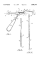
- FIG. 1 is a side view of a first embodiment of the drill guide apparatus of the present invention
- FIG. 2 is a side view of a drill for use with the drill guide apparatus of the present invention
- FIG. 3 is a side view of a fixation pin for use with the drill guide apparatus of the present invention and in the method of the present invention
- FIG. 4 is a perspective view illustrating the method of the present invention during placement of the drill guide at the patient's iliac crest and with the distal tip of the guide inserted and pushed along the inner table of the pelvis;
- FIG. 5 is a perspective view of the first embodiment of the apparatus of the present invention and illustrating the method step of the present invention that includes surgical placement of a drilled opening in the patient's pelvis;
- FIG. 6 is a partial perspective view of the first embodiment of the drill guide apparatus of the present invention.
- FIG. 7 is a partial perspective view of the guide apparatus of the present invention.
- FIG. 8 is an anterior view of the patient's pelvis illustrating placement of a plurality of fixation pins using the method of the present invention
- FIG. 9 is a top view of the patient's pelvis illustrating placement of fixation pins and convention external fixation system using the method and apparatus of the present invention.
- FIG. 10 is side view of the patient's pelvis illustrating the placement of a fixation pin using the method and apparatus of the present invention
- FIG. 11 is side view of a second embodiment of the apparatus of the present invention.
- FIG. 12 is a sectional view of the second embodiment of the apparatus of the present invention.
- FIG. 13 is a perspective view of a third embodiment of the apparatus of the present invention.
- FIG. 14 is a perspective view of the third embodiment of the apparatus of the present invention, showing the probe in unlocked position.
- FIGS. 15-16 are sectional fragmentary views of the third embodiment of the apparatus of the present invention illustrating the probe and locking collar.
- FIGS. 1-3 and 6-7 illustrate a first preferred embodiment of the apparatus of the present invention designated generally by the numeral 10.
- Pelvic drill guide 10 includes an instrument body 11 that includes a barrel 12, handle 20 and a probe 24.
- Barrel 12 includes a proximal end 13 and distal end 14.
- Barrel 12 has a generally cylindrically shaped longitudinally extending, open ended bore 15 for receiving a drill during use.
- Barrel 12 includes an enlarged central cylindrical portion 19 a smaller proximal cylindrical portion 16 and a smaller cylindrical portion 17 at distal end 14.
- Distal end 14 of barrel 12 carries a pair of teeth 18 that are circumferentially spaced about the smaller cylindrical portion 17 of barrel 12 as shown in FIG. 7.
- Teeth 18 project forward in a line that is generally parallel to the central longitudinal axis of bore 15. The teeth 18 are used to grip the patient's tissue at the pelvis as shown in FIG. 4.
- Barrel 12 includes enlarged section 19 to which is attached handle.
- the handle 20 includes a gripping surface 21 and arm 23 that extends between gripping surface 21 and enlarged portion 19 of barrel 12 at connection 22.
- Elongated probe 24 of pelvic drill guide 10 includes a straight section 26 that is attached by welding for example to the outer surface of enlarged section 19 of barrel 12.
- the probe or tip 24 also includes a bend 27, straight section 28, bend 29, straight section 30, bend 31, and straight section 32.
- the probe 24 carries a pointed distal tip 33.
- the surgeon inserts the probe 24 along the inner table of the pelvis P until the teeth 18 engage the pelvic rim.
- the distal tip 33 is engaging the inner table of the pelvis and the teeth 18 of the barrel 12 engage the iliac crest.
- the surgeon can place a drill 34 into the central longitudinally extending bore 15 of barrel 12 to form surgically drilled openings in the patient's pelvis P.
- the drill 34 as seen is FIG. 2, can be generally cylindrically shaped, having a larger cylindrical portion 35, a smaller cylindrically shaped cutting portion 37, and an annular shoulder 36 positioned between the section 35, 37.
- the drill 34 includes a cutting distal tip 38 and a proximal end that includes a plurality of flats 39 for forming a connection between the drill 34 and a drill chuck (not shown).
- FIG. 3 An acceptable pin 40 is shown in FIG. 3 that includes a cylindrical unthreaded section 41, a helically threaded section 43, and a distal tip 44 that can define a self tapping thread. Arrow 42 indicates the position between the threaded and non-threaded sections 43,41.
- FIGS. 4-5 and 8-10 the method of the present invention is illustrated more particularly.
- the surgeon has placed instrument body 10 in proper position before inserting drill 34 into the bore 15 of barrel 12.
- the surgeon has already formed a small incision (for example two (2) centimeters) on the side of the pelvis just proximal to ASIS and exposing the iliac crest 47.
- the muscle is elevated medial to the iliac crest and the free tip 33 of guide apparatus 10 is inserted and pushed along the inner table 45 of the pelvis P.
- the guide apparatus 10 is centered on the iliac crest 47 in such a manner that pins 40 will be inserted in an anteroposterior direction almost perpendicular to the plane of the operating table.
- Drill 34 is inserted into bore 15 of barrel 12 as shown in FIG. 5 and a pilot hole is drilled through the cortex of the iliac crest into the iliac bone.
- the guide apparatus 10 prevents inadvertent penetration of either cortex from occurring.
- a fixation pin 40 is manually inserted using a T-wrench, for example.
- a second surgically formed pilot hole is drilled in a similar fashion and a second pin 40 is inserted again by means of a T-wrench, for example.
- the surgically formed openings are indicated in phantom lines by the numeral 46. The surgeon can then mount a conventional external fixation system 75 to the pins 40, as shown in FIG. 9.
- the numeral 50 indicates the central longitudinal axis of the cylindrically shaped bore 15 that extends longitudinally through barrel 12.
- the pointed tip 33 is spaced a few millimeters (for example three (3) millimeters) from the central longitudinal axis 50. This places the pointer tip 33 adjacent the outer surface of drill 34 at cylindrically shaped cutting portion 37.
- the surgeon By placing the tip 33 on the patient's inner table 45 (as shown in FIG. 4), at the position indicated by arrow 48 in FIG. 4, the surgeon insures that the drill will track into the patient's pelvis but not break through the surface 45 or outcrop inadvertently. Rather, the tip 33 is placed tightly against the surface 45 and the drill tracks under the surface 45. This insurance is provided by the geometry of the central longitudinal axis 50 being off-set with respect to the pointer tip 33.
- the barrel 12 has a bore 15A that is sized and shaped to receive interchangeable sleeves 51, 53 each having an internal sleeve bore 52,54 respectively. This allows different diameter drills 34 to be used with the same instrument body 11.
- Each sleeve 51, 53 has a large cylindrical collar 52A, 54A respectively that acts as a stop (see FIG. 12) when sleeve 51, 53 occupies bore 15A of barrel 12.
- FIGS. 13-16 illustrate a third embodiment of the apparatus of the present invention designated generally by the numeral 57.
- Drill guide apparatus 57 provides an instrument body 58 having a distal end 59 and a proximal end 60.
- a longitudinally extending open ended bore is provided for receiving a drill during use.
- the method of the present invention is the same with the embodiment of FIGS. 13-16 as with the embodiments of FIGS. 1-12.
- a locking collar is provided for locking a probe in position wherein the probe pivots about the instrument body 58.
- Instrument body 58 includes a larger cylindrical section 62 and a smaller cylindrical section 63. Smaller cylindrical section 63 carries a pair of teeth 64 at distal end 59 of the apparatus 57.
- the apparatus 57 is supported using handle 65 that is connected with strut 66 to instrument body 58.
- Locking collar 67 is generally cylindrically shaped, and affixes to a smaller diameter cylindrically shaped section 68 of larger cylindrical section 62.
- Locking collar 67 is in the form of an elongated hollow cylinder having a longitudinal slot 69.
- the slot 69 can be aligned with probe 72 (see FIG. 15). In this position, the probe can pivot about pivot 71, allowing the probe to move away from the central longitudinal axis of bore 61 as shown in FIG. 14.
- Probe 72 has a configuration similar to the configuration of the probes of the embodiments shown in FIGS. 1-12.
- the locking collar 67 is a regular cylinder which rotates around instrument body 58 and more particularly around the larger cylindrical section 62 thereof. Locking is obtained by simply rotating the collar 67.
- the probe 72 is "buried" in the thickness of the drill sleeve, occupying a position in longitudinally extending recess 70. In locking position as in open position, the collar 67 does not protrude beyond instrument body 58 as shown in FIGS. 13-16.
- the hinged probe 72 pivots about pivot 71 when the guide 57 is removed from the patient.
- the hinged probe 72 prevents the tip 73 from catching the lip of the iliac crest when the guide apparatus 57 is removed from the patient.
Abstract
Description
______________________________________ PARTS LIST Part Number Description ______________________________________ 10 pelvic drill guide apparatus 11instrument body 12barrel 13proximal end 14distal end 15cylindrical bore 15A cylindrical bore 16cylindrical portion 17cylindrical portion 18teeth 19enlarged section 20 handle 21 grippingsurface 22connection 23arm 24probe 25connection 26straight section 27bend 28straight section 29bend 30straight section 31bend 32straight section 33 pointedtip 34drill 35 largercylindrical portion 36annular shoulder 37 smallercylindrical cutting portion 38 cutting tip 39tool flats 40 pin 41cylindrical unthreaded section 42arrow 43 threadedsection 44cutting tip 45 inner table 46pilot hole 47iliac crest 48arrow 49arrow 50axis 51 interchangeable sleeve -large bore 52 internal sleeve bore (large) 52A cylindrical collar -large bore 53 interchangeable sleeve bore -small bore 54 internal sleeve bore (small) 54A cylindrical collar - small bore 55enlarged diameter collar 57drill guide apparatus 58instrument body 59distal end 60proximal end 61 bore 62 largercylindrical section 63 smallercylindrical section 64teeth 65 handle 66strut 67locking collar 68smaller diameter section 69slot 70longitudinal recess 71pivot 72probe 73tip 75 conventional external fixation system ______________________________________
Claims (15)
Priority Applications (1)
| Application Number | Priority Date | Filing Date | Title |
|---|---|---|---|
| US08/329,068 US5601550A (en) | 1994-10-25 | 1994-10-25 | Pelvic pin guide system for insertion of pins into iliac bone |
Applications Claiming Priority (1)
| Application Number | Priority Date | Filing Date | Title |
|---|---|---|---|
| US08/329,068 US5601550A (en) | 1994-10-25 | 1994-10-25 | Pelvic pin guide system for insertion of pins into iliac bone |
Publications (1)
| Publication Number | Publication Date |
|---|---|
| US5601550A true US5601550A (en) | 1997-02-11 |
Family
ID=23283722
Family Applications (1)
| Application Number | Title | Priority Date | Filing Date |
|---|---|---|---|
| US08/329,068 Expired - Lifetime US5601550A (en) | 1994-10-25 | 1994-10-25 | Pelvic pin guide system for insertion of pins into iliac bone |
Country Status (1)
| Country | Link |
|---|---|
| US (1) | US5601550A (en) |
Cited By (126)
| Publication number | Priority date | Publication date | Assignee | Title |
|---|---|---|---|---|
| US5951561A (en) * | 1998-06-30 | 1999-09-14 | Smith & Nephew, Inc. | Minimally invasive intramedullary nail insertion instruments and method |
| USD420132S (en) * | 1997-11-03 | 2000-02-01 | Surgical Navigation Technologies | Drill guide |
| EP1074230A1 (en) * | 1999-08-05 | 2001-02-07 | Tornier Sa | Malleolar implant for a partial or total ankle prosthesis and ancillary equipment for fitting such an implant |
| WO2001019265A1 (en) * | 1999-09-15 | 2001-03-22 | Synthes Ag Chur | Repositioning device for bone fragments |
| US6287313B1 (en) | 1999-11-23 | 2001-09-11 | Sdgi Holdings, Inc. | Screw delivery system and method |
| US6342057B1 (en) | 2000-04-28 | 2002-01-29 | Synthes (Usa) | Remotely aligned surgical drill guide |
| US6379364B1 (en) | 2000-04-28 | 2002-04-30 | Synthes (Usa) | Dual drill guide for a locking bone plate |
| WO2002060330A1 (en) * | 2001-01-29 | 2002-08-08 | Stephen Ritland | Retractor and method for spinal pedicle screw placement |
| US20030083689A1 (en) * | 2001-10-30 | 2003-05-01 | Simonson Robert E. | Non cannulated dilators |
| US20030083688A1 (en) * | 2001-10-30 | 2003-05-01 | Simonson Robert E. | Configured and sized cannula |
| US20030093078A1 (en) * | 2001-09-28 | 2003-05-15 | Stephen Ritland | Connection rod for screw or hook polyaxial system and method of use |
| US20030171751A1 (en) * | 2002-02-20 | 2003-09-11 | Stephen Ritland | Pedicle screw connector apparatus and method |
| US20030181984A1 (en) * | 2002-02-14 | 2003-09-25 | Abendschein Walter F. | Method and instrumentation for patello-femoral joint replacement |
| US20030191470A1 (en) * | 2002-04-05 | 2003-10-09 | Stephen Ritland | Dynamic fixation device and method of use |
| US20030236447A1 (en) * | 2001-01-29 | 2003-12-25 | Stephen Ritland | Retractor and method for spinal pedicle screw placement |
| US6679888B2 (en) | 2001-05-29 | 2004-01-20 | Synthes | Femur lever |
| US20040015170A1 (en) * | 2000-05-01 | 2004-01-22 | Tallarida Steven J. | System and method for joint resurface repair |
| US6692503B2 (en) * | 1999-10-13 | 2004-02-17 | Sdgi Holdings, Inc | System and method for securing a plate to the spinal column |
| US6692434B2 (en) | 2000-09-29 | 2004-02-17 | Stephen Ritland | Method and device for retractor for microsurgical intermuscular lumbar arthrodesis |
| US20040106928A1 (en) * | 2002-12-03 | 2004-06-03 | Steven Ek | Tibial resurfacing system |
| US20040152955A1 (en) * | 2003-02-04 | 2004-08-05 | Mcginley Shawn E. | Guidance system for rotary surgical instrument |
| US20040172023A1 (en) * | 2000-06-30 | 2004-09-02 | Stephen Ritland | Polyaxial connection device and method |
| US20040171930A1 (en) * | 2003-02-04 | 2004-09-02 | Zimmer Technology, Inc. | Guidance system for rotary surgical instrument |
| US20040254428A1 (en) * | 2003-05-22 | 2004-12-16 | Stephen Ritland | Intermuscular guide for retractor insertion and method of use |
| EP1488746A1 (en) * | 2003-06-20 | 2004-12-22 | Stryker Trauma GmbH | Device for correctly inserting a guide wire for a drill in a bone |
| US20050015093A1 (en) * | 2003-07-16 | 2005-01-20 | Suh Sean S. | Plating system with compression drill guide |
| US20050027301A1 (en) * | 2003-08-01 | 2005-02-03 | Pascal Stihl | Drill guide assembly for a bone fixation device |
| US20050038444A1 (en) * | 2003-08-13 | 2005-02-17 | Binder Lawrence J. | Quick-release drill-guide assembly for bone-plate |
| US20050080418A1 (en) * | 2001-10-30 | 2005-04-14 | Simonson Robert E. | Instruments and methods for minimally invasive spine surgery |
| WO2005053548A1 (en) * | 2003-12-03 | 2005-06-16 | Synthes Ag Chur | Device for repositioning bone fractures |
| US20050154398A1 (en) * | 2002-12-03 | 2005-07-14 | Anthony Miniaci | Retrograde delivery of resurfacing devices |
| US20050203490A1 (en) * | 2002-03-29 | 2005-09-15 | Depuy Spine, Inc. | Apparatus and method for targeting for surgical procedures |
| US20050228233A1 (en) * | 2000-09-29 | 2005-10-13 | Stephen Ritland | Method and device for microsurgical intermuscular spinal surgery |
| US20050261698A1 (en) * | 2004-05-19 | 2005-11-24 | Sean Powell | Snap-lock for drill sleeve |
| US20060004401A1 (en) * | 2004-06-30 | 2006-01-05 | Abernathie Dennis L | Elongateable surgical port and dilator |
| US20060020343A1 (en) * | 2002-12-03 | 2006-01-26 | Ek Steven W | System for articular surface replacement |
| US20060063978A1 (en) * | 2004-09-20 | 2006-03-23 | Stephen Ritland | Opposing parallel bladed retractor and method of use |
| WO2006039483A2 (en) * | 2004-10-01 | 2006-04-13 | Implant Innovations, Inc. | Bone drill system with highly visible depth markings |
| US20060085006A1 (en) * | 2002-12-03 | 2006-04-20 | Ek Steven W | System and method for retrograde procedure |
| US20070005143A1 (en) * | 2004-11-22 | 2007-01-04 | Ek Steven W | Articular surface implant and delivery system |
| US20070016193A1 (en) * | 2002-05-08 | 2007-01-18 | Stephen Ritland | Dynamic fixation device and method of use |
| US20070043365A1 (en) * | 2005-07-19 | 2007-02-22 | Stephen Ritland | Rod extension for extending fusion construct |
| WO2007017097A3 (en) * | 2005-07-28 | 2007-04-19 | Mikai S P A | Apparatus for external fixation of the pelvic ring |
| US20070239153A1 (en) * | 2006-02-22 | 2007-10-11 | Hodorek Robert A | Computer assisted surgery system using alternative energy technology |
| US20080195113A1 (en) * | 2007-02-14 | 2008-08-14 | Arthrosurface Incorporated | Bone Cement Delivery Device |
| US20080200917A1 (en) * | 2007-02-15 | 2008-08-21 | Lin Shih-Wei | Targeting device for femur intertrochanteric fracture |
| US20080306487A1 (en) * | 2007-06-06 | 2008-12-11 | Rickey Hart | Drill Guide And Method For Placing A Fixation Device Hole |
| US20090048575A1 (en) * | 2004-10-13 | 2009-02-19 | Biocomposites Limited | Trocar with obturator having longitudinal through holes for guiding wires |
| US20090240256A1 (en) * | 2008-03-19 | 2009-09-24 | Biomet Manufacturing Corp. | Method And Apparatus For Implanting an Augment |
| US7604641B2 (en) | 2000-05-01 | 2009-10-20 | Arthrosurface Incorporated | System and method for joint resurface repair |
| US7618462B2 (en) | 2000-05-01 | 2009-11-17 | Arthrosurface Incorporated | System and method for joint resurface repair |
| US7655025B2 (en) | 2001-09-28 | 2010-02-02 | Stephen Ritland | Adjustable rod and connector device and method of use |
| US7678151B2 (en) | 2000-05-01 | 2010-03-16 | Ek Steven W | System and method for joint resurface repair |
| US7713305B2 (en) | 2000-05-01 | 2010-05-11 | Arthrosurface, Inc. | Articular surface implant |
| US20100121324A1 (en) * | 2008-06-24 | 2010-05-13 | Jeff Tyber | Fixation system, an intramedullary fixation assembly and method of use |
| US20100256639A1 (en) * | 2008-06-24 | 2010-10-07 | Jeff Tyber | Fixation system, an intramedullary fixation assembly and method of use |
| US20100256638A1 (en) * | 2008-06-24 | 2010-10-07 | Jeff Tyber | Intraosseous intramedullary fixation assembly and method of use |
| US20100324556A1 (en) * | 2008-06-24 | 2010-12-23 | Jeff Tyber | Fixation system, an intramedullary fixation assembly and method of use |
| US7896883B2 (en) | 2000-05-01 | 2011-03-01 | Arthrosurface, Inc. | Bone resurfacing system and method |
| US7914545B2 (en) | 2002-12-03 | 2011-03-29 | Arthrosurface, Inc | System and method for retrograde procedure |
| US20110118739A1 (en) * | 2008-06-24 | 2011-05-19 | Jeff Tyber | Intramedullary fixation assembly and method of use |
| US7951163B2 (en) | 2003-11-20 | 2011-05-31 | Arthrosurface, Inc. | Retrograde excision system and apparatus |
| US7959564B2 (en) | 2006-07-08 | 2011-06-14 | Stephen Ritland | Pedicle seeker and retractor, and methods of use |
| USRE42525E1 (en) | 1999-03-12 | 2011-07-05 | Depuy Spine, Inc. | Cannula and sizing insertion method |
| US20110190591A1 (en) * | 2010-01-29 | 2011-08-04 | Palmer Andrew K | Surgical retractor |
| US20110208194A1 (en) * | 2009-08-20 | 2011-08-25 | Howmedica Osteonics Corp. | Flexible acl instrumentation, kit and method |
| US20110213367A1 (en) * | 2008-06-24 | 2011-09-01 | Jeff Tyber | Intramedullary fixation screw, a fixation system, and method of fixation of the subtalar joint |
| US20110230884A1 (en) * | 2008-06-24 | 2011-09-22 | Adam Mantzaris | Hybrid intramedullary fixation assembly and method of use |
| US20120046526A1 (en) * | 2010-08-21 | 2012-02-23 | New York Society For The Ruptured And Crippled Maintaining The Hospital For Special Surgery | Instruments for use in femoroacetabular impingement procedures |
| WO2012061661A1 (en) * | 2010-11-04 | 2012-05-10 | Smith & Nephew ,Inc | Arthroscopic joint repair |
| WO2012061642A1 (en) * | 2010-11-03 | 2012-05-10 | Smith & Nephew, Inc | Drill guide |
| US8177841B2 (en) | 2000-05-01 | 2012-05-15 | Arthrosurface Inc. | System and method for joint resurface repair |
| US20120197254A1 (en) * | 2008-06-24 | 2012-08-02 | Scott Wolfe | Intramedullary Fixation Assembly and Method of Use |
| US20120265205A1 (en) * | 2011-04-13 | 2012-10-18 | Howmedica Osteonics Corp. | Flexible acl instrumentation, kit and method |
| US8388624B2 (en) | 2003-02-24 | 2013-03-05 | Arthrosurface Incorporated | Trochlear resurfacing system and method |
| WO2013071432A1 (en) * | 2011-11-14 | 2013-05-23 | The University Of British Columbia | Intramedullary fixation system for management of pelvic and acetabular fractures |
| US8617176B2 (en) | 2011-08-24 | 2013-12-31 | Depuy Mitek, Llc | Cross pinning guide devices and methods |
| US20140243838A1 (en) * | 2013-02-28 | 2014-08-28 | Robert Gorsline | Systems, methods, and apparatuses for reaming bone elements |
| WO2015006781A3 (en) * | 2013-07-12 | 2015-03-12 | Arthromeda, Inc. | Aligning a medical device with a pelvic axis |
| US9066716B2 (en) | 2011-03-30 | 2015-06-30 | Arthrosurface Incorporated | Suture coil and suture sheath for tissue repair |
| EP2907461A1 (en) | 2014-02-18 | 2015-08-19 | Clement Max Leonard Werner | Bone fastening system |
| CN104887301A (en) * | 2015-06-26 | 2015-09-09 | 陈伟 | Pelvic fracture microinvasive intramedullary fixation device |
| US9198676B2 (en) | 2011-07-26 | 2015-12-01 | Howmedica Osteonics Corp. | PCL guides for drilling tibial and femoral tunnels |
| US20150342659A1 (en) * | 2011-12-29 | 2015-12-03 | DePuy Synthes Products, Inc. | Suprapatellar insertion system, kit and method |
| US9216048B2 (en) | 2009-03-18 | 2015-12-22 | Integrated Spinal Concepts, Inc. | Image-guided minimal-step placement of screw into bone |
| WO2016035981A1 (en) * | 2014-09-04 | 2016-03-10 | 아이메디컴(주) | Medical device for holding wire pin |
| US9283076B2 (en) | 2009-04-17 | 2016-03-15 | Arthrosurface Incorporated | Glenoid resurfacing system and method |
| US9358029B2 (en) | 2006-12-11 | 2016-06-07 | Arthrosurface Incorporated | Retrograde resection apparatus and method |
| US9408646B2 (en) | 2003-09-03 | 2016-08-09 | DePuy Synthes Products, Inc. | Bone plate with captive clips |
| US9414870B2 (en) | 2003-09-03 | 2016-08-16 | DePuy Synthes Products, Inc. | Translatable carriage fixation system |
| US9468448B2 (en) | 2012-07-03 | 2016-10-18 | Arthrosurface Incorporated | System and method for joint resurfacing and repair |
| US9492200B2 (en) | 2013-04-16 | 2016-11-15 | Arthrosurface Incorporated | Suture system and method |
| US9566078B2 (en) | 2012-01-19 | 2017-02-14 | Stryker European Holdings I, Llc | Guide sleeve for suprapatellar surgery |
| EP2941208A4 (en) * | 2013-01-07 | 2017-03-01 | Pivot Medical, Inc. | Flexible drill bit and angled drill guide for use with the same |
| WO2016209947A3 (en) * | 2015-06-22 | 2017-05-04 | Smith & Nephew, Inc. | Internal pelvic fixator |
| US9662126B2 (en) | 2009-04-17 | 2017-05-30 | Arthrosurface Incorporated | Glenoid resurfacing system and method |
| CN106963470A (en) * | 2017-04-06 | 2017-07-21 | 陈同林 | A kind of minimally invasive replacement and fixation system of pelvis |
| US9826992B2 (en) | 2007-12-21 | 2017-11-28 | Smith & Nephew, Inc. | Multiple portal guide |
| US9848894B2 (en) | 2012-01-05 | 2017-12-26 | Pivot Medical, Inc. | Flexible drill bit and angled drill guide for use with the same |
| US9861492B2 (en) | 2014-03-07 | 2018-01-09 | Arthrosurface Incorporated | Anchor for an implant assembly |
| US9888936B2 (en) | 2010-09-27 | 2018-02-13 | Smith & Nephew, Inc. | Device and methods for use during arthroscopic surgery |
| US9913636B2 (en) | 2007-12-21 | 2018-03-13 | Smith & Nephew, Inc. | Multiple portal guide |
| US9937055B1 (en) | 2016-11-28 | 2018-04-10 | Spine Wave, Inc. | Scoring implant trial and implant inserter for spinal fusion system |
| US9962188B2 (en) | 2013-10-29 | 2018-05-08 | Cardinal Health 247. Inc. | External fixation system and methods of use |
| US9968464B2 (en) | 2014-01-17 | 2018-05-15 | Spine Wave, Inc. | Spinal fusion system |
| US9986992B2 (en) | 2014-10-28 | 2018-06-05 | Stryker Corporation | Suture anchor and associated methods of use |
| US10022131B1 (en) | 2012-01-05 | 2018-07-17 | Pivot Medical, Inc. | Flexible drill bit and angled drill guide for use with the same |
| US10258394B2 (en) | 2014-10-14 | 2019-04-16 | The University Of British Columbia | Systems and methods for intermedullary bone fixation |
| US10307188B2 (en) | 2014-03-06 | 2019-06-04 | The University Of British Columbia | Shape adaptable intramedullary fixation device |
| US10357314B2 (en) | 2015-07-08 | 2019-07-23 | Stryker European Holdings I, Llc | Instrumentation and method for repair of a bone fracture |
| US10448944B2 (en) | 2011-11-23 | 2019-10-22 | Howmedica Osteonics Corp. | Filamentary fixation device |
| US10582935B2 (en) | 2012-01-05 | 2020-03-10 | Stryker Puerto Rico Limited | Flexible drill bit |
| US10624748B2 (en) | 2014-03-07 | 2020-04-21 | Arthrosurface Incorporated | System and method for repairing articular surfaces |
| US10624752B2 (en) | 2006-07-17 | 2020-04-21 | Arthrosurface Incorporated | Tibial resurfacing system and method |
| US10888435B2 (en) | 2017-10-05 | 2021-01-12 | Spine Wave, Inc. | Modular inserter for anterior cervical cage |
| US10945743B2 (en) | 2009-04-17 | 2021-03-16 | Arthrosurface Incorporated | Glenoid repair system and methods of use thereof |
| US11058437B2 (en) | 2018-03-29 | 2021-07-13 | Zimmer Biomet Spine, Inc. | Systems and methods for pedicle screw implantation using flexible drill bit |
| US11160663B2 (en) | 2017-08-04 | 2021-11-02 | Arthrosurface Incorporated | Multicomponent articular surface implant |
| US11331094B2 (en) | 2013-04-22 | 2022-05-17 | Stryker Corporation | Method and apparatus for attaching tissue to bone |
| US11419645B2 (en) | 2016-10-05 | 2022-08-23 | University Of British Columbia | Intramedullary fixation device with shape locking interface |
| US11478358B2 (en) | 2019-03-12 | 2022-10-25 | Arthrosurface Incorporated | Humeral and glenoid articular surface implant systems and methods |
| US20220378442A1 (en) * | 2019-11-08 | 2022-12-01 | Johnson Yiu-Nam Lau | Devices and methods for orienting a surgical device |
| US11517330B2 (en) * | 2018-12-21 | 2022-12-06 | Tarek O. Souryal | Pregnant guide pin drill passer |
| US11607319B2 (en) | 2014-03-07 | 2023-03-21 | Arthrosurface Incorporated | System and method for repairing articular surfaces |
| US11712276B2 (en) | 2011-12-22 | 2023-08-01 | Arthrosurface Incorporated | System and method for bone fixation |
| US11832856B2 (en) | 2018-10-17 | 2023-12-05 | The University Of British Columbia | Bone-fixation device and system |
Citations (8)
| Publication number | Priority date | Publication date | Assignee | Title |
|---|---|---|---|---|
| DE681828C (en) * | 1938-03-29 | 1939-10-02 | Heinrich C Ulrich | Auxiliary device for nailing femoral neck fractures |
| DE681829C (en) * | 1938-10-19 | 1939-10-03 | Heinrich C Ulrich | Auxiliary device for nailing femoral neck fractures |
| SU839510A1 (en) * | 1979-03-26 | 1981-06-23 | Frantsen Yurij K | Device for guiding wire |
| US4292964A (en) * | 1979-01-19 | 1981-10-06 | Ulrich Max B | Method of and apparatus for pinning a fractured pelvis |
| US4570624A (en) * | 1983-08-10 | 1986-02-18 | Henry Ford Hospital | Universal guide for inserting parallel pins |
| US4708139A (en) * | 1986-02-24 | 1987-11-24 | Dunbar Iv William H | Arthroscopic drill guide |
| US4848327A (en) * | 1988-05-23 | 1989-07-18 | Perdue Kevin D | Apparatus and procedure for blind alignment of fasteners extended through transverse holes in an orthopedic locking nail |
| US5163940A (en) * | 1991-03-04 | 1992-11-17 | American Cyanamid Company | Surgical drill guide for tibia |
-
1994
- 1994-10-25 US US08/329,068 patent/US5601550A/en not_active Expired - Lifetime
Patent Citations (8)
| Publication number | Priority date | Publication date | Assignee | Title |
|---|---|---|---|---|
| DE681828C (en) * | 1938-03-29 | 1939-10-02 | Heinrich C Ulrich | Auxiliary device for nailing femoral neck fractures |
| DE681829C (en) * | 1938-10-19 | 1939-10-03 | Heinrich C Ulrich | Auxiliary device for nailing femoral neck fractures |
| US4292964A (en) * | 1979-01-19 | 1981-10-06 | Ulrich Max B | Method of and apparatus for pinning a fractured pelvis |
| SU839510A1 (en) * | 1979-03-26 | 1981-06-23 | Frantsen Yurij K | Device for guiding wire |
| US4570624A (en) * | 1983-08-10 | 1986-02-18 | Henry Ford Hospital | Universal guide for inserting parallel pins |
| US4708139A (en) * | 1986-02-24 | 1987-11-24 | Dunbar Iv William H | Arthroscopic drill guide |
| US4848327A (en) * | 1988-05-23 | 1989-07-18 | Perdue Kevin D | Apparatus and procedure for blind alignment of fasteners extended through transverse holes in an orthopedic locking nail |
| US5163940A (en) * | 1991-03-04 | 1992-11-17 | American Cyanamid Company | Surgical drill guide for tibia |
Cited By (301)
| Publication number | Priority date | Publication date | Assignee | Title |
|---|---|---|---|---|
| USD420132S (en) * | 1997-11-03 | 2000-02-01 | Surgical Navigation Technologies | Drill guide |
| US5951561A (en) * | 1998-06-30 | 1999-09-14 | Smith & Nephew, Inc. | Minimally invasive intramedullary nail insertion instruments and method |
| USRE39995E1 (en) * | 1998-06-30 | 2008-01-01 | Smith & Nephew, Inc. | Minimally invasive intramedullary nail insertion instruments and method |
| USRE45571E1 (en) | 1999-03-12 | 2015-06-23 | DePuy Synthes Products, Inc. | Cannula and sizing insertion method |
| USRE46978E1 (en) | 1999-03-12 | 2018-08-07 | DePuy Synthes Products, Inc. | Cannula and sizing insertion method |
| USRE42525E1 (en) | 1999-03-12 | 2011-07-05 | Depuy Spine, Inc. | Cannula and sizing insertion method |
| US7993346B2 (en) | 1999-08-05 | 2011-08-09 | Tornier Sas | Method for placing a malleolar implant |
| US20090048687A1 (en) * | 1999-08-05 | 2009-02-19 | Tornier Sas | Method for placing a malleolar implant for partial or total ankle prosthesis |
| EP1074230A1 (en) * | 1999-08-05 | 2001-02-07 | Tornier Sa | Malleolar implant for a partial or total ankle prosthesis and ancillary equipment for fitting such an implant |
| EP1398009A3 (en) * | 1999-08-05 | 2004-10-13 | Tornier | Ancillary equipment for inserting a malleolar implant for a partial or total ankle prosthesis and implant suitable for being inserted with this equipment |
| EP1398009A2 (en) * | 1999-08-05 | 2004-03-17 | Tornier | Ancillary equipment for inserting a malleolar implant for a partial or total ankle prosthesis and implant suitable for being inserted with this equipment |
| WO2001019265A1 (en) * | 1999-09-15 | 2001-03-22 | Synthes Ag Chur | Repositioning device for bone fragments |
| US6692503B2 (en) * | 1999-10-13 | 2004-02-17 | Sdgi Holdings, Inc | System and method for securing a plate to the spinal column |
| US6287313B1 (en) | 1999-11-23 | 2001-09-11 | Sdgi Holdings, Inc. | Screw delivery system and method |
| US6562046B2 (en) | 1999-11-23 | 2003-05-13 | Sdgi Holdings, Inc. | Screw delivery system and method |
| US6379364B1 (en) | 2000-04-28 | 2002-04-30 | Synthes (Usa) | Dual drill guide for a locking bone plate |
| US6342057B1 (en) | 2000-04-28 | 2002-01-29 | Synthes (Usa) | Remotely aligned surgical drill guide |
| US9357989B2 (en) | 2000-05-01 | 2016-06-07 | Arthrosurface Incorporated | System and method for joint resurface repair |
| US7618462B2 (en) | 2000-05-01 | 2009-11-17 | Arthrosurface Incorporated | System and method for joint resurface repair |
| US9204873B2 (en) | 2000-05-01 | 2015-12-08 | Arthrosurface Incorporated | System and method for joint resurface repair |
| US20110152869A1 (en) * | 2000-05-01 | 2011-06-23 | Arthrosurface, Inc. | Bone Resurfacing System and Method |
| US8864827B2 (en) | 2000-05-01 | 2014-10-21 | Arthrosurface Inc. | System and method for joint resurface repair |
| US8177841B2 (en) | 2000-05-01 | 2012-05-15 | Arthrosurface Inc. | System and method for joint resurface repair |
| US8540717B2 (en) | 2000-05-01 | 2013-09-24 | Arthrosurface Incorporated | System and method for joint resurface repair |
| US9055955B2 (en) | 2000-05-01 | 2015-06-16 | Arthrosurface Inc. | Bone resurfacing system and method |
| US7713305B2 (en) | 2000-05-01 | 2010-05-11 | Arthrosurface, Inc. | Articular surface implant |
| US20040015170A1 (en) * | 2000-05-01 | 2004-01-22 | Tallarida Steven J. | System and method for joint resurface repair |
| US7510558B2 (en) | 2000-05-01 | 2009-03-31 | Arthrosurface, Inc. | System and method for joint resurface repair |
| US8147559B2 (en) | 2000-05-01 | 2012-04-03 | Arthrosurface Incorporated | System and method for joint resurface repair |
| US20100070045A1 (en) * | 2000-05-01 | 2010-03-18 | Arthrosurface Incorparated | System and Method for Joint Resurface Repair |
| US7857817B2 (en) | 2000-05-01 | 2010-12-28 | Arthrosurface Inc. | System and method for joint resurface repair |
| US7678151B2 (en) | 2000-05-01 | 2010-03-16 | Ek Steven W | System and method for joint resurface repair |
| US7604641B2 (en) | 2000-05-01 | 2009-10-20 | Arthrosurface Incorporated | System and method for joint resurface repair |
| US7896883B2 (en) | 2000-05-01 | 2011-03-01 | Arthrosurface, Inc. | Bone resurfacing system and method |
| US20040172023A1 (en) * | 2000-06-30 | 2004-09-02 | Stephen Ritland | Polyaxial connection device and method |
| US7753939B2 (en) | 2000-06-30 | 2010-07-13 | Stephen Ritland | Polyaxial connection device and method |
| US6692434B2 (en) | 2000-09-29 | 2004-02-17 | Stephen Ritland | Method and device for retractor for microsurgical intermuscular lumbar arthrodesis |
| US7166073B2 (en) | 2000-09-29 | 2007-01-23 | Stephen Ritland | Method and device for microsurgical intermuscular spinal surgery |
| US20040138534A1 (en) * | 2000-09-29 | 2004-07-15 | Stephen Ritland | Method and device for retractor for microsurgical intermuscular lumbar arthrodesis |
| US7214186B2 (en) | 2000-09-29 | 2007-05-08 | Stephen Ritland | Method and device for retractor for microsurgical intermuscular lumbar arthrodesis |
| US20050228233A1 (en) * | 2000-09-29 | 2005-10-13 | Stephen Ritland | Method and device for microsurgical intermuscular spinal surgery |
| US20030236447A1 (en) * | 2001-01-29 | 2003-12-25 | Stephen Ritland | Retractor and method for spinal pedicle screw placement |
| US6951538B2 (en) | 2001-01-29 | 2005-10-04 | Depuy Spine, Inc. | Retractor and method for spinal pedicle screw placement |
| US6929606B2 (en) | 2001-01-29 | 2005-08-16 | Depuy Spine, Inc. | Retractor and method for spinal pedicle screw placement |
| WO2002060330A1 (en) * | 2001-01-29 | 2002-08-08 | Stephen Ritland | Retractor and method for spinal pedicle screw placement |
| US6679888B2 (en) | 2001-05-29 | 2004-01-20 | Synthes | Femur lever |
| US9622790B2 (en) | 2001-09-19 | 2017-04-18 | Warsaw Orthopedic, Inc. | Rod extension for extending fusion construct |
| US7985245B2 (en) | 2001-09-28 | 2011-07-26 | Stephen Ritland | Connection rod for screw or hook polyaxial system and method of use |
| US20030093078A1 (en) * | 2001-09-28 | 2003-05-15 | Stephen Ritland | Connection rod for screw or hook polyaxial system and method of use |
| US7207992B2 (en) | 2001-09-28 | 2007-04-24 | Stephen Ritland | Connection rod for screw or hook polyaxial system and method of use |
| US7695498B2 (en) | 2001-09-28 | 2010-04-13 | Stephen Ritland | Connection rod for screw or hook polyaxial system and method of use |
| US7655025B2 (en) | 2001-09-28 | 2010-02-02 | Stephen Ritland | Adjustable rod and connector device and method of use |
| US9028551B2 (en) | 2001-10-30 | 2015-05-12 | DePuy Synthes Products, Inc. | Configured and sized cannula |
| US7824410B2 (en) | 2001-10-30 | 2010-11-02 | Depuy Spine, Inc. | Instruments and methods for minimally invasive spine surgery |
| US20030083689A1 (en) * | 2001-10-30 | 2003-05-01 | Simonson Robert E. | Non cannulated dilators |
| US7008431B2 (en) | 2001-10-30 | 2006-03-07 | Depuy Spine, Inc. | Configured and sized cannula |
| US20030083688A1 (en) * | 2001-10-30 | 2003-05-01 | Simonson Robert E. | Configured and sized cannula |
| US8361151B2 (en) | 2001-10-30 | 2013-01-29 | Depuy Spine, Inc. | Configured and sized cannula |
| US8235999B2 (en) | 2001-10-30 | 2012-08-07 | Depuy Spine, Inc. | Configured and sized cannula |
| US20100222824A1 (en) * | 2001-10-30 | 2010-09-02 | Depuy Spine, Inc. | Configured and sized cannula |
| US20050004593A1 (en) * | 2001-10-30 | 2005-01-06 | Depuy Spine, Inc. | Non cannulated dilators |
| US10004488B2 (en) | 2001-10-30 | 2018-06-26 | DePuy Synthes Products, Inc. | Configured and sized cannula |
| US9226782B2 (en) | 2001-10-30 | 2016-01-05 | DePuy Synthes Products, Inc. | Instruments and methods for minimally invasive spine surgery |
| US9532774B2 (en) | 2001-10-30 | 2017-01-03 | DePuy Synthes Products, Inc. | Configured and sized cannula |
| US8444678B2 (en) | 2001-10-30 | 2013-05-21 | Depuy Spine, Inc. | Instruments and methods for minimally invasive spine surgery |
| US8852244B2 (en) | 2001-10-30 | 2014-10-07 | DePuy Synthes Products, LLC | Configured and sized cannula |
| US20050216002A1 (en) * | 2001-10-30 | 2005-09-29 | Depuy Spine, Inc. | Configured and sized cannula |
| US8556905B2 (en) | 2001-10-30 | 2013-10-15 | Depuy Spine, Inc. | Configured and sized cannula |
| US20050080418A1 (en) * | 2001-10-30 | 2005-04-14 | Simonson Robert E. | Instruments and methods for minimally invasive spine surgery |
| US8192437B2 (en) | 2001-10-30 | 2012-06-05 | Depuy Spine, Inc. | Configured and sized cannula |
| US8226726B2 (en) | 2002-02-14 | 2012-07-24 | Biomet Manufacturing Corp. | Method and instrumentation for patello-femoral joint replacement |
| WO2003068119A3 (en) * | 2002-02-14 | 2003-12-04 | Walter F Abendschein | Method and instrumentation for patello-femoral joint replacement |
| AU2003219773B2 (en) * | 2002-02-14 | 2007-02-01 | Biomet Spain Orthopaedics S.L. | Method and instrumentation for patello-femoral joint replacement |
| US20030181984A1 (en) * | 2002-02-14 | 2003-09-25 | Abendschein Walter F. | Method and instrumentation for patello-femoral joint replacement |
| US20090326660A1 (en) * | 2002-02-14 | 2009-12-31 | Biomet Manufacturing Corp. | Method and Instrumentation for Patello-Femoral Joint Replacement |
| US7763047B2 (en) | 2002-02-20 | 2010-07-27 | Stephen Ritland | Pedicle screw connector apparatus and method |
| US8221459B2 (en) | 2002-02-20 | 2012-07-17 | Stephen Ritland | Pedicle screw connector apparatus and method |
| US20110022094A1 (en) * | 2002-02-20 | 2011-01-27 | Stephen Ritland | Pedicle Screw Connector Apparatus and Method |
| US20030171751A1 (en) * | 2002-02-20 | 2003-09-11 | Stephen Ritland | Pedicle screw connector apparatus and method |
| US20050203490A1 (en) * | 2002-03-29 | 2005-09-15 | Depuy Spine, Inc. | Apparatus and method for targeting for surgical procedures |
| US6966910B2 (en) | 2002-04-05 | 2005-11-22 | Stephen Ritland | Dynamic fixation device and method of use |
| US20030191470A1 (en) * | 2002-04-05 | 2003-10-09 | Stephen Ritland | Dynamic fixation device and method of use |
| US8932334B2 (en) | 2002-04-05 | 2015-01-13 | Stephen Ritland | Dynamic fixation device and method of use |
| US8690922B2 (en) | 2002-05-08 | 2014-04-08 | Stephen Ritland | Dynamic fixation device and method of use |
| US8585739B2 (en) | 2002-05-08 | 2013-11-19 | Stephen Ritland | Dynamic fixation device and method of use |
| US20070016193A1 (en) * | 2002-05-08 | 2007-01-18 | Stephen Ritland | Dynamic fixation device and method of use |
| US9232967B2 (en) | 2002-05-08 | 2016-01-12 | Stephen Ritland | Dynamic fixation device and method of use |
| US7682375B2 (en) | 2002-05-08 | 2010-03-23 | Stephen Ritland | Dynamic fixation device and method of use |
| US8685062B2 (en) | 2002-05-08 | 2014-04-01 | Stephen Ritland | Dynamic fixation device and method of use |
| US9918744B2 (en) | 2002-05-08 | 2018-03-20 | Stephen Ritland | Dynamic fixation device and method of use |
| US8486111B2 (en) | 2002-05-08 | 2013-07-16 | Stephen Ritland | Dynamic fixation device and method of use |
| US8663230B2 (en) | 2002-12-03 | 2014-03-04 | Arthrosurface Incorporated | Retrograde delivery of resurfacing devices |
| US7896885B2 (en) | 2002-12-03 | 2011-03-01 | Arthrosurface Inc. | Retrograde delivery of resurfacing devices |
| US8523872B2 (en) | 2002-12-03 | 2013-09-03 | Arthrosurface Incorporated | Tibial resurfacing system |
| US8556902B2 (en) | 2002-12-03 | 2013-10-15 | Arthrosurface Incorporated | System and method for retrograde procedure |
| US20050154398A1 (en) * | 2002-12-03 | 2005-07-14 | Anthony Miniaci | Retrograde delivery of resurfacing devices |
| US9044343B2 (en) | 2002-12-03 | 2015-06-02 | Arthrosurface Incorporated | System for articular surface replacement |
| US20040106928A1 (en) * | 2002-12-03 | 2004-06-03 | Steven Ek | Tibial resurfacing system |
| US7163541B2 (en) | 2002-12-03 | 2007-01-16 | Arthrosurface Incorporated | Tibial resurfacing system |
| US20060085006A1 (en) * | 2002-12-03 | 2006-04-20 | Ek Steven W | System and method for retrograde procedure |
| US20110196434A1 (en) * | 2002-12-03 | 2011-08-11 | Arthrosurface Incorporated | System and method for retrograde procedure |
| US10076343B2 (en) | 2002-12-03 | 2018-09-18 | Arthrosurface Incorporated | System for articular surface replacement |
| US8926615B2 (en) | 2002-12-03 | 2015-01-06 | Arthrosurface, Inc. | System and method for retrograde procedure |
| US20060020343A1 (en) * | 2002-12-03 | 2006-01-26 | Ek Steven W | System for articular surface replacement |
| EP1426013A1 (en) * | 2002-12-03 | 2004-06-09 | ArthroSurface, Inc. | Tibial resurfacing system |
| US7901408B2 (en) | 2002-12-03 | 2011-03-08 | Arthrosurface, Inc. | System and method for retrograde procedure |
| US8361159B2 (en) | 2002-12-03 | 2013-01-29 | Arthrosurface, Inc. | System for articular surface replacement |
| US7914545B2 (en) | 2002-12-03 | 2011-03-29 | Arthrosurface, Inc | System and method for retrograde procedure |
| US20040171930A1 (en) * | 2003-02-04 | 2004-09-02 | Zimmer Technology, Inc. | Guidance system for rotary surgical instrument |
| US20040152955A1 (en) * | 2003-02-04 | 2004-08-05 | Mcginley Shawn E. | Guidance system for rotary surgical instrument |
| US9931211B2 (en) | 2003-02-24 | 2018-04-03 | Arthrosurface Incorporated | Trochlear resurfacing system and method |
| US8388624B2 (en) | 2003-02-24 | 2013-03-05 | Arthrosurface Incorporated | Trochlear resurfacing system and method |
| US9351745B2 (en) | 2003-02-24 | 2016-05-31 | Arthrosurface Incorporated | Trochlear resurfacing system and method |
| US11337819B2 (en) | 2003-02-24 | 2022-05-24 | Arthrosurface Incorporated | Trochlear resurfacing system and method |
| US10624749B2 (en) | 2003-02-24 | 2020-04-21 | Arthrosurface Incorporated | Trochlear resurfacing system and method |
| US8262571B2 (en) | 2003-05-22 | 2012-09-11 | Stephen Ritland | Intermuscular guide for retractor insertion and method of use |
| US20040254428A1 (en) * | 2003-05-22 | 2004-12-16 | Stephen Ritland | Intermuscular guide for retractor insertion and method of use |
| EP1488746A1 (en) * | 2003-06-20 | 2004-12-22 | Stryker Trauma GmbH | Device for correctly inserting a guide wire for a drill in a bone |
| US7422594B2 (en) * | 2003-06-20 | 2008-09-09 | Stryker Trauma Gmbh | Drilling tool guide wire alignment device |
| US7981114B2 (en) | 2003-06-20 | 2011-07-19 | Stryker Trauma Gmbh | Drilling tool guide wire alignment device |
| US20080086144A1 (en) * | 2003-06-20 | 2008-04-10 | Stryker Trauma Gmbh | Drilling tool guide wire alignment device |
| US20040260307A1 (en) * | 2003-06-20 | 2004-12-23 | Stryker Trauma Gmbh | Drilling tool guide wire alignment device |
| US20050015093A1 (en) * | 2003-07-16 | 2005-01-20 | Suh Sean S. | Plating system with compression drill guide |
| US7731721B2 (en) | 2003-07-16 | 2010-06-08 | Synthes Usa, Llc | Plating system with multiple function drill guide |
| US20050015092A1 (en) * | 2003-07-16 | 2005-01-20 | Rathbun David S. | Plating system with multiple function drill guide |
| US7081119B2 (en) | 2003-08-01 | 2006-07-25 | Hfsc Company | Drill guide assembly for a bone fixation device |
| US20050027301A1 (en) * | 2003-08-01 | 2005-02-03 | Pascal Stihl | Drill guide assembly for a bone fixation device |
| US7357804B2 (en) | 2003-08-13 | 2008-04-15 | Synthes (U.S.A.) | Quick-release drill-guide assembly for bone-plate |
| US20050038444A1 (en) * | 2003-08-13 | 2005-02-17 | Binder Lawrence J. | Quick-release drill-guide assembly for bone-plate |
| US10368927B2 (en) | 2003-09-03 | 2019-08-06 | DePuy Synthes Products, Inc. | Bone plate with captive clips |
| US9408646B2 (en) | 2003-09-03 | 2016-08-09 | DePuy Synthes Products, Inc. | Bone plate with captive clips |
| US9414870B2 (en) | 2003-09-03 | 2016-08-16 | DePuy Synthes Products, Inc. | Translatable carriage fixation system |
| US7951163B2 (en) | 2003-11-20 | 2011-05-31 | Arthrosurface, Inc. | Retrograde excision system and apparatus |
| WO2005053548A1 (en) * | 2003-12-03 | 2005-06-16 | Synthes Ag Chur | Device for repositioning bone fractures |
| US20050261698A1 (en) * | 2004-05-19 | 2005-11-24 | Sean Powell | Snap-lock for drill sleeve |
| US8974466B2 (en) | 2004-05-19 | 2015-03-10 | DePuy Synthes Products, Inc. | Snap-lock for drill sleeve |
| US7033363B2 (en) | 2004-05-19 | 2006-04-25 | Sean Powell | Snap-lock for drill sleeve |
| US9480488B2 (en) | 2004-05-19 | 2016-11-01 | DePuy Synthes Products, Inc. | Snap-lock for drill sleeve |
| US7909843B2 (en) | 2004-06-30 | 2011-03-22 | Thompson Surgical Instruments, Inc. | Elongateable surgical port and dilator |
| US20060004401A1 (en) * | 2004-06-30 | 2006-01-05 | Abernathie Dennis L | Elongateable surgical port and dilator |
| US20060063978A1 (en) * | 2004-09-20 | 2006-03-23 | Stephen Ritland | Opposing parallel bladed retractor and method of use |
| US7455639B2 (en) | 2004-09-20 | 2008-11-25 | Stephen Ritland | Opposing parallel bladed retractor and method of use |
| WO2006039483A2 (en) * | 2004-10-01 | 2006-04-13 | Implant Innovations, Inc. | Bone drill system with highly visible depth markings |
| WO2006039483A3 (en) * | 2004-10-01 | 2007-03-01 | Implant Innovations Inc | Bone drill system with highly visible depth markings |
| US20090048575A1 (en) * | 2004-10-13 | 2009-02-19 | Biocomposites Limited | Trocar with obturator having longitudinal through holes for guiding wires |
| US7828853B2 (en) | 2004-11-22 | 2010-11-09 | Arthrosurface, Inc. | Articular surface implant and delivery system |
| US8961614B2 (en) | 2004-11-22 | 2015-02-24 | Arthrosurface, Inc. | Articular surface implant and delivery system |
| US20070005143A1 (en) * | 2004-11-22 | 2007-01-04 | Ek Steven W | Articular surface implant and delivery system |
| US8845694B2 (en) | 2005-07-19 | 2014-09-30 | Warsaw Orthopedic, Inc. | Rod extension for extending fusion construct |
| US8021399B2 (en) | 2005-07-19 | 2011-09-20 | Stephen Ritland | Rod extension for extending fusion construct |
| US20070043365A1 (en) * | 2005-07-19 | 2007-02-22 | Stephen Ritland | Rod extension for extending fusion construct |
| WO2007017097A3 (en) * | 2005-07-28 | 2007-04-19 | Mikai S P A | Apparatus for external fixation of the pelvic ring |
| US20090264884A1 (en) * | 2005-07-28 | 2009-10-22 | Alessandro Masse | Apparatus for External Fixation of the Pelvic Ring |
| US20070239153A1 (en) * | 2006-02-22 | 2007-10-11 | Hodorek Robert A | Computer assisted surgery system using alternative energy technology |
| US7959564B2 (en) | 2006-07-08 | 2011-06-14 | Stephen Ritland | Pedicle seeker and retractor, and methods of use |
| US10624752B2 (en) | 2006-07-17 | 2020-04-21 | Arthrosurface Incorporated | Tibial resurfacing system and method |
| US11471289B2 (en) | 2006-07-17 | 2022-10-18 | Arthrosurface Incorporated | Tibial resurfacing system and method |
| US10045788B2 (en) | 2006-12-11 | 2018-08-14 | Arthrosurface Incorporated | Retrograde resection apparatus and method |
| US9358029B2 (en) | 2006-12-11 | 2016-06-07 | Arthrosurface Incorporated | Retrograde resection apparatus and method |
| US10959740B2 (en) | 2006-12-11 | 2021-03-30 | Arthrosurface Incorporated | Retrograde resection apparatus and method |
| US20080195113A1 (en) * | 2007-02-14 | 2008-08-14 | Arthrosurface Incorporated | Bone Cement Delivery Device |
| US20080200917A1 (en) * | 2007-02-15 | 2008-08-21 | Lin Shih-Wei | Targeting device for femur intertrochanteric fracture |
| US7815646B2 (en) * | 2007-06-06 | 2010-10-19 | Karl Storz Gmbh & Co. Kg | Drill guide and method for placing a fixation device hole |
| US20090287219A1 (en) * | 2007-06-06 | 2009-11-19 | Rickey Hart | Drill Guide And Method For Placing A Fixation Device Hole |
| JP2008302227A (en) * | 2007-06-06 | 2008-12-18 | Karl Storz Endovision Inc | Drill guide and method for placing fixation device hole |
| US20080306487A1 (en) * | 2007-06-06 | 2008-12-11 | Rickey Hart | Drill Guide And Method For Placing A Fixation Device Hole |
| US7927340B2 (en) | 2007-06-06 | 2011-04-19 | Karl Storz Gmbh & Co. Kg | Drill guide and method for placing a fixation device hole |
| US9826992B2 (en) | 2007-12-21 | 2017-11-28 | Smith & Nephew, Inc. | Multiple portal guide |
| US9913636B2 (en) | 2007-12-21 | 2018-03-13 | Smith & Nephew, Inc. | Multiple portal guide |
| US20090240256A1 (en) * | 2008-03-19 | 2009-09-24 | Biomet Manufacturing Corp. | Method And Apparatus For Implanting an Augment |
| US8328806B2 (en) * | 2008-06-24 | 2012-12-11 | Extremity Medical, Llc | Fixation system, an intramedullary fixation assembly and method of use |
| US20100256638A1 (en) * | 2008-06-24 | 2010-10-07 | Jeff Tyber | Intraosseous intramedullary fixation assembly and method of use |
| US9044282B2 (en) * | 2008-06-24 | 2015-06-02 | Extremity Medical Llc | Intraosseous intramedullary fixation assembly and method of use |
| US20110230884A1 (en) * | 2008-06-24 | 2011-09-22 | Adam Mantzaris | Hybrid intramedullary fixation assembly and method of use |
| US9017329B2 (en) * | 2008-06-24 | 2015-04-28 | Extremity Medical, Llc | Intramedullary fixation assembly and method of use |
| US8920476B2 (en) | 2008-06-24 | 2014-12-30 | Extremity Medical, Llc | Fixation system, an intramedullary fixation assembly and method of use |
| US20110118739A1 (en) * | 2008-06-24 | 2011-05-19 | Jeff Tyber | Intramedullary fixation assembly and method of use |
| US8920453B2 (en) | 2008-06-24 | 2014-12-30 | Extremity Medical, Llc | Fixation system, an intramedullary fixation assembly and method of use |
| US20100121324A1 (en) * | 2008-06-24 | 2010-05-13 | Jeff Tyber | Fixation system, an intramedullary fixation assembly and method of use |
| US20150133936A1 (en) * | 2008-06-24 | 2015-05-14 | Extremity Medical L.L.C. | Intraosseous intramedullary fixation assembly and method of use |
| US20110213367A1 (en) * | 2008-06-24 | 2011-09-01 | Jeff Tyber | Intramedullary fixation screw, a fixation system, and method of fixation of the subtalar joint |
| US8900274B2 (en) | 2008-06-24 | 2014-12-02 | Extremity Medical Llc | Fixation system, an intramedullary fixation assembly and method of use |
| US8303589B2 (en) * | 2008-06-24 | 2012-11-06 | Extremity Medical Llc | Fixation system, an intramedullary fixation assembly and method of use |
| US9364271B2 (en) * | 2008-06-24 | 2016-06-14 | Extremity Medical Llc | Intraosseous intramedullary fixation assembly and method of use |
| US8313487B2 (en) | 2008-06-24 | 2012-11-20 | Extremity Medical Llc | Fixation system, an intramedullary fixation assembly and method of use |
| US20100324556A1 (en) * | 2008-06-24 | 2010-12-23 | Jeff Tyber | Fixation system, an intramedullary fixation assembly and method of use |
| US9289220B2 (en) * | 2008-06-24 | 2016-03-22 | Extremity Medical Llc | Intramedullary fixation assembly and method of use |
| US20120197254A1 (en) * | 2008-06-24 | 2012-08-02 | Scott Wolfe | Intramedullary Fixation Assembly and Method of Use |
| US8343199B2 (en) | 2008-06-24 | 2013-01-01 | Extremity Medical, Llc | Intramedullary fixation screw, a fixation system, and method of fixation of the subtalar joint |
| US20100256639A1 (en) * | 2008-06-24 | 2010-10-07 | Jeff Tyber | Fixation system, an intramedullary fixation assembly and method of use |
| US9216048B2 (en) | 2009-03-18 | 2015-12-22 | Integrated Spinal Concepts, Inc. | Image-guided minimal-step placement of screw into bone |
| US11471220B2 (en) | 2009-03-18 | 2022-10-18 | Integrated Spinal Concepts, Inc. | Image-guided minimal-step placement of screw into bone |
| US10603116B2 (en) | 2009-03-18 | 2020-03-31 | Integrated Spinal Concepts, Inc. | Image-guided minimal-step placement of screw into bone |
| US11478259B2 (en) | 2009-04-17 | 2022-10-25 | Arthrosurface, Incorporated | Glenoid resurfacing system and method |
| US10478200B2 (en) | 2009-04-17 | 2019-11-19 | Arthrosurface Incorporated | Glenoid resurfacing system and method |
| US9283076B2 (en) | 2009-04-17 | 2016-03-15 | Arthrosurface Incorporated | Glenoid resurfacing system and method |
| US9662126B2 (en) | 2009-04-17 | 2017-05-30 | Arthrosurface Incorporated | Glenoid resurfacing system and method |
| US10945743B2 (en) | 2009-04-17 | 2021-03-16 | Arthrosurface Incorporated | Glenoid repair system and methods of use thereof |
| US9232954B2 (en) | 2009-08-20 | 2016-01-12 | Howmedica Osteonics Corp. | Flexible ACL instrumentation, kit and method |
| US20110208194A1 (en) * | 2009-08-20 | 2011-08-25 | Howmedica Osteonics Corp. | Flexible acl instrumentation, kit and method |
| US10238404B2 (en) | 2009-08-20 | 2019-03-26 | Howmedica Osteonics Corp. | Flexible ACL instrumentation, kit and method |
| US10231744B2 (en) * | 2009-08-20 | 2019-03-19 | Howmedica Osteonics Corp. | Flexible ACL instrumentation, kit and method |
| US11364041B2 (en) * | 2009-08-20 | 2022-06-21 | Howmedica Osteonics Corp. | Flexible ACL instrumentation, kit and method |
| US20150127012A1 (en) * | 2009-08-20 | 2015-05-07 | Howmedica Osteonics Corp. | Flexible acl instrumentation, kit and method |
| US20110190591A1 (en) * | 2010-01-29 | 2011-08-04 | Palmer Andrew K | Surgical retractor |
| US20120046526A1 (en) * | 2010-08-21 | 2012-02-23 | New York Society For The Ruptured And Crippled Maintaining The Hospital For Special Surgery | Instruments for use in femoroacetabular impingement procedures |
| US9750491B2 (en) | 2010-08-21 | 2017-09-05 | New York Society For The Ruptured And Crippled Maintaining The Hospital For Special Surgery | Instruments for use in femoroacetabular impingement procedures |
| US9119644B2 (en) * | 2010-08-21 | 2015-09-01 | New York Society For The Ruptured And Crippled Maintaining The Hospital For Special Surgery | Instruments for use in femoroacetabular impingement procedures |
| US9888936B2 (en) | 2010-09-27 | 2018-02-13 | Smith & Nephew, Inc. | Device and methods for use during arthroscopic surgery |
| WO2012061642A1 (en) * | 2010-11-03 | 2012-05-10 | Smith & Nephew, Inc | Drill guide |
| US10219812B2 (en) | 2010-11-03 | 2019-03-05 | Smith & Nephew, Inc. | Drill guide |
| WO2012061639A1 (en) * | 2010-11-03 | 2012-05-10 | Smith & Nephew, Inc. | Drill guide |
| WO2012061661A1 (en) * | 2010-11-04 | 2012-05-10 | Smith & Nephew ,Inc | Arthroscopic joint repair |
| US20160089165A1 (en) * | 2010-11-04 | 2016-03-31 | Smith & Nephew, Inc. | Anthroscopic joint repair |
| US9155547B2 (en) | 2010-11-04 | 2015-10-13 | Smith & Nephew, Inc. | Arthroscopic joint repair |
| US9066716B2 (en) | 2011-03-30 | 2015-06-30 | Arthrosurface Incorporated | Suture coil and suture sheath for tissue repair |
| US20120265205A1 (en) * | 2011-04-13 | 2012-10-18 | Howmedica Osteonics Corp. | Flexible acl instrumentation, kit and method |
| US9795398B2 (en) * | 2011-04-13 | 2017-10-24 | Howmedica Osteonics Corp. | Flexible ACL instrumentation, kit and method |
| US9198676B2 (en) | 2011-07-26 | 2015-12-01 | Howmedica Osteonics Corp. | PCL guides for drilling tibial and femoral tunnels |
| US10512475B2 (en) | 2011-08-24 | 2019-12-24 | Depuy Synthes Products, Inc | Cross pinning guide devices and methods |
| US8617176B2 (en) | 2011-08-24 | 2013-12-31 | Depuy Mitek, Llc | Cross pinning guide devices and methods |
| US9271745B2 (en) | 2011-08-24 | 2016-03-01 | Depuy Mitek, Llc | Cross pinning guide devices and methods |
| EP2779928A4 (en) * | 2011-11-14 | 2015-07-15 | Univ British Columbia | Intramedullary fixation system for management of pelvic and acetabular fractures |
| WO2013071432A1 (en) * | 2011-11-14 | 2013-05-23 | The University Of British Columbia | Intramedullary fixation system for management of pelvic and acetabular fractures |
| US9839435B2 (en) | 2011-11-14 | 2017-12-12 | The University Of British Columbia | Intramedullary fixation system for management of pelvic and acetabular fractures |
| CN104203132B (en) * | 2011-11-14 | 2017-08-01 | 不列颠哥伦比亚大学 | Medullary fixation system for the treatment of pelvis and fracture of acetabulum |
| CN104203132A (en) * | 2011-11-14 | 2014-12-10 | 不列颠哥伦比亚大学 | Intramedullary fixation system for management of pelvic and acetabular fractures |
| EP3326558A1 (en) * | 2011-11-14 | 2018-05-30 | The University of British Columbia | Intramedullary fixation system for management of pelvic and acetabular fractures |
| US11529148B2 (en) | 2011-11-14 | 2022-12-20 | The University Of British Columbia | Intramedullary fixation system for management of pelvic and acetabular fractures |
| US11844508B2 (en) | 2011-11-23 | 2023-12-19 | Howmedica Osteonics Corp. | Filamentary fixation device |
| US10448944B2 (en) | 2011-11-23 | 2019-10-22 | Howmedica Osteonics Corp. | Filamentary fixation device |
| US11712276B2 (en) | 2011-12-22 | 2023-08-01 | Arthrosurface Incorporated | System and method for bone fixation |
| US11253307B2 (en) | 2011-12-29 | 2022-02-22 | DePuy Synthes Products, Inc. | Suprapatellar insertion system, kit and method |
| US20150342659A1 (en) * | 2011-12-29 | 2015-12-03 | DePuy Synthes Products, Inc. | Suprapatellar insertion system, kit and method |
| US10117699B2 (en) * | 2011-12-29 | 2018-11-06 | DePuy Synthes Products, Inc. | Suprapatellar insertion system, kit and method |
| US10582935B2 (en) | 2012-01-05 | 2020-03-10 | Stryker Puerto Rico Limited | Flexible drill bit |
| US10022131B1 (en) | 2012-01-05 | 2018-07-17 | Pivot Medical, Inc. | Flexible drill bit and angled drill guide for use with the same |
| US11779349B1 (en) | 2012-01-05 | 2023-10-10 | Stryker Puerto Rico, LLC | Flexible drill bit and angled drill guide for use with the same |
| US10856889B1 (en) | 2012-01-05 | 2020-12-08 | Stryker Puerto Rico Limited | Flexible drill bit and angled drill guide for use with the same |
| US9848894B2 (en) | 2012-01-05 | 2017-12-26 | Pivot Medical, Inc. | Flexible drill bit and angled drill guide for use with the same |
| US10925621B2 (en) | 2012-01-05 | 2021-02-23 | Stryker Puerto Rico Limited | Flexible drill bit and angled drill guide for use with the same |
| US9999430B2 (en) | 2012-01-19 | 2018-06-19 | Stryker European Holdings I, Llc | Guide sleeve for suprapatellar surgery |
| US9566078B2 (en) | 2012-01-19 | 2017-02-14 | Stryker European Holdings I, Llc | Guide sleeve for suprapatellar surgery |
| US11191552B2 (en) | 2012-07-03 | 2021-12-07 | Arthrosurface, Incorporated | System and method for joint resurfacing and repair |
| US9468448B2 (en) | 2012-07-03 | 2016-10-18 | Arthrosurface Incorporated | System and method for joint resurfacing and repair |
| US10307172B2 (en) | 2012-07-03 | 2019-06-04 | Arthrosurface Incorporated | System and method for joint resurfacing and repair |
| EP2941208A4 (en) * | 2013-01-07 | 2017-03-01 | Pivot Medical, Inc. | Flexible drill bit and angled drill guide for use with the same |
| US20140243838A1 (en) * | 2013-02-28 | 2014-08-28 | Robert Gorsline | Systems, methods, and apparatuses for reaming bone elements |
| US9855063B2 (en) * | 2013-02-28 | 2018-01-02 | Jonathan Feibel | Systems, methods, and apparatuses for reaming bone elements |
| US9492200B2 (en) | 2013-04-16 | 2016-11-15 | Arthrosurface Incorporated | Suture system and method |
| US10695096B2 (en) | 2013-04-16 | 2020-06-30 | Arthrosurface Incorporated | Suture system and method |
| US11648036B2 (en) | 2013-04-16 | 2023-05-16 | Arthrosurface Incorporated | Suture system and method |
| US11331094B2 (en) | 2013-04-22 | 2022-05-17 | Stryker Corporation | Method and apparatus for attaching tissue to bone |
| US9622705B2 (en) | 2013-07-12 | 2017-04-18 | Arthromeda, Inc. | Systems and methods for aligning a medical device with a pelvic axis |
| WO2015006781A3 (en) * | 2013-07-12 | 2015-03-12 | Arthromeda, Inc. | Aligning a medical device with a pelvic axis |
| US9375178B2 (en) | 2013-07-12 | 2016-06-28 | Arthromeda, Inc. | Systems and methods for aligning a medical device with a pelvic axis |
| US9962188B2 (en) | 2013-10-29 | 2018-05-08 | Cardinal Health 247. Inc. | External fixation system and methods of use |
| US9968464B2 (en) | 2014-01-17 | 2018-05-15 | Spine Wave, Inc. | Spinal fusion system |
| US10219916B2 (en) | 2014-01-17 | 2019-03-05 | Spine Wave, Inc. | Method for fusing spinal vertebrae |
| US11051952B2 (en) | 2014-01-17 | 2021-07-06 | Spine Wave, Inc. | Spinal implant system |
| EP2907461A1 (en) | 2014-02-18 | 2015-08-19 | Clement Max Leonard Werner | Bone fastening system |
| WO2015125056A1 (en) | 2014-02-18 | 2015-08-27 | Werner Clément Max Leonard | Bone fastening system |
| US10363076B2 (en) | 2014-02-18 | 2019-07-30 | Clement Max Leonard WERNER | Bone fastening system |
| US11369421B2 (en) | 2014-03-06 | 2022-06-28 | The University of British Columbia and British Columbia Cancer Agency Branch | Shape adaptable intramedullary fixation device |
| US10307188B2 (en) | 2014-03-06 | 2019-06-04 | The University Of British Columbia | Shape adaptable intramedullary fixation device |
| US11766334B2 (en) | 2014-03-07 | 2023-09-26 | Arthrosurface Incorporated | System and method for repairing articular surfaces |
| US11083587B2 (en) | 2014-03-07 | 2021-08-10 | Arthrosurface Incorporated | Implant and anchor assembly |
| US9962265B2 (en) | 2014-03-07 | 2018-05-08 | Arthrosurface Incorporated | System and method for repairing articular surfaces |
| US10624754B2 (en) | 2014-03-07 | 2020-04-21 | Arthrosurface Incorporated | System and method for repairing articular surfaces |
| US10624748B2 (en) | 2014-03-07 | 2020-04-21 | Arthrosurface Incorporated | System and method for repairing articular surfaces |
| US9861492B2 (en) | 2014-03-07 | 2018-01-09 | Arthrosurface Incorporated | Anchor for an implant assembly |
| US10575957B2 (en) | 2014-03-07 | 2020-03-03 | Arthrosurface Incoporated | Anchor for an implant assembly |
| US11607319B2 (en) | 2014-03-07 | 2023-03-21 | Arthrosurface Incorporated | System and method for repairing articular surfaces |
| US9931219B2 (en) | 2014-03-07 | 2018-04-03 | Arthrosurface Incorporated | Implant and anchor assembly |
| WO2016035981A1 (en) * | 2014-09-04 | 2016-03-10 | 아이메디컴(주) | Medical device for holding wire pin |
| US10973559B2 (en) | 2014-10-14 | 2021-04-13 | University Of British Columbia | Systems and methods for intermedullary bone fixation |
| US10258394B2 (en) | 2014-10-14 | 2019-04-16 | The University Of British Columbia | Systems and methods for intermedullary bone fixation |
| US9986992B2 (en) | 2014-10-28 | 2018-06-05 | Stryker Corporation | Suture anchor and associated methods of use |
| US11006945B2 (en) | 2014-10-28 | 2021-05-18 | Stryker Corporation | Suture anchor and associated methods of use |
| US11490930B2 (en) * | 2015-06-22 | 2022-11-08 | Smith & Nephew, Inc. | Internal pelvic fixator |
| WO2016209947A3 (en) * | 2015-06-22 | 2017-05-04 | Smith & Nephew, Inc. | Internal pelvic fixator |
| US10575874B2 (en) * | 2015-06-22 | 2020-03-03 | Smith & Nephew, Inc. | Internal pelvic fixator |
| CN104887301B (en) * | 2015-06-26 | 2017-03-01 | 陈伟 | A kind of minimally invasive Medullary fixation device of fracture of pelvis |
| CN104887301A (en) * | 2015-06-26 | 2015-09-09 | 陈伟 | Pelvic fracture microinvasive intramedullary fixation device |
| US10357314B2 (en) | 2015-07-08 | 2019-07-23 | Stryker European Holdings I, Llc | Instrumentation and method for repair of a bone fracture |
| US11419645B2 (en) | 2016-10-05 | 2022-08-23 | University Of British Columbia | Intramedullary fixation device with shape locking interface |
| US9937055B1 (en) | 2016-11-28 | 2018-04-10 | Spine Wave, Inc. | Scoring implant trial and implant inserter for spinal fusion system |
| US10524925B2 (en) | 2016-11-28 | 2020-01-07 | Spine Wave, Inc. | Method for spinal fusion |
| US10603186B2 (en) | 2016-11-28 | 2020-03-31 | Spine Wave, Inc. | Spinal implant inserter assembly for use in spinal fusion |
| US10500060B2 (en) | 2016-11-28 | 2019-12-10 | Spine Wave, Inc. | Disc preparation instrument for use in spinal fusion |
| CN106963470A (en) * | 2017-04-06 | 2017-07-21 | 陈同林 | A kind of minimally invasive replacement and fixation system of pelvis |
| US11160663B2 (en) | 2017-08-04 | 2021-11-02 | Arthrosurface Incorporated | Multicomponent articular surface implant |
| US11813177B2 (en) | 2017-10-05 | 2023-11-14 | Spine Wave, Inc. | Spinal surgery kit comprising a plurality of modular inserter tips |
| US10888435B2 (en) | 2017-10-05 | 2021-01-12 | Spine Wave, Inc. | Modular inserter for anterior cervical cage |
| US10888434B2 (en) | 2017-10-05 | 2021-01-12 | Spine Wave, Inc. | Modular scoring trial for anterior cervical cage |
| US11819222B2 (en) | 2017-10-05 | 2023-11-21 | Spine Wave, Inc. | Depth stop instrument for use in spinal surgery |
| US11058437B2 (en) | 2018-03-29 | 2021-07-13 | Zimmer Biomet Spine, Inc. | Systems and methods for pedicle screw implantation using flexible drill bit |
| US11832856B2 (en) | 2018-10-17 | 2023-12-05 | The University Of British Columbia | Bone-fixation device and system |
| US11517330B2 (en) * | 2018-12-21 | 2022-12-06 | Tarek O. Souryal | Pregnant guide pin drill passer |
| US11478358B2 (en) | 2019-03-12 | 2022-10-25 | Arthrosurface Incorporated | Humeral and glenoid articular surface implant systems and methods |
| US20220378442A1 (en) * | 2019-11-08 | 2022-12-01 | Johnson Yiu-Nam Lau | Devices and methods for orienting a surgical device |
Similar Documents
| Publication | Publication Date | Title |
|---|---|---|
| US5601550A (en) | Pelvic pin guide system for insertion of pins into iliac bone | |
| EP0400062B1 (en) | Apparatus for reducing a fracture | |
| US7175631B2 (en) | Radiolucent aiming guide | |
| US5312412A (en) | Fixation alignment guide for surgical use | |
| USRE39995E1 (en) | Minimally invasive intramedullary nail insertion instruments and method | |
| US6149654A (en) | Intra-articular drill | |
| US6663562B2 (en) | Surgical retractor | |
| AU719525B2 (en) | Freely separable surgical drill guide and plate | |
| CN101014291B (en) | Implant assembly device | |
| US10034674B2 (en) | Universal anterior cruciate ligament repair and reconstruction system | |
| JP2598736B2 (en) | Surgical instruments for positioning osteosynthesis mounting elements, especially bone screws | |
| US7594917B2 (en) | Method and apparatus for fixing a graft in a bone tunnel | |
| US5403322A (en) | Drill guide and method for avoiding intramedullary nails in the placement of bone pins | |
| US5569262A (en) | Guide tool for surgical devices | |
| US7766825B2 (en) | Retractor with interchangeable retractor blades | |
| AU2007231608A1 (en) | Methods and devices for ligament repair | |
| AU2009222580A1 (en) | Method for replacing a ligament in a knee | |
| US20030018340A1 (en) | Method and apparatus for installing cannula | |
| CN109512556A (en) | For assembling the method and apparatus of orthopaedic prosthesis | |
| JP2023162360A (en) | Implantable glenoid components | |
| CN210811348U (en) | Marrow expanding guide pin positioning tube and femoral intertrochanteric fracture guide pin positioner | |
| WO1995035180A1 (en) | Drill guide apparatus and methods including selectable guides | |
| US8403943B2 (en) | Insertion system for implanting a medical device and surgical methods | |
| US20240024127A1 (en) | Intramedullary Prosthesis Removal Systems and Methods Thereof | |
| JP3311662B2 (en) | Target device capable of preventing head rotation |
Legal Events
| Date | Code | Title | Description |
|---|---|---|---|
| FEPP | Fee payment procedure |
Free format text: ENTITY STATUS SET TO SMALL (ORIGINAL EVENT CODE: SMAL); ENTITY STATUS OF PATENT OWNER: LARGE ENTITY |
|
| REMI | Maintenance fee reminder mailed | ||
| FEPP | Fee payment procedure |
Free format text: PETITION RELATED TO MAINTENANCE FEES FILED (ORIGINAL EVENT CODE: PMFP); ENTITY STATUS OF PATENT OWNER: LARGE ENTITY |
|
| FEPP | Fee payment procedure |
Free format text: PETITION RELATED TO MAINTENANCE FEES GRANTED (ORIGINAL EVENT CODE: PMFG); ENTITY STATUS OF PATENT OWNER: LARGE ENTITY |
|
| FP | Lapsed due to failure to pay maintenance fee |
Effective date: 20010211 |
|
| FPAY | Fee payment |
Year of fee payment: 4 |
|
| SULP | Surcharge for late payment | ||
| STCF | Information on status: patent grant |
Free format text: PATENTED CASE |
|
| PRDP | Patent reinstated due to the acceptance of a late maintenance fee |
Effective date: 20010608 |
|
| REFU | Refund |
Free format text: REFUND - SURCHARGE, PETITION TO ACCEPT PYMT AFTER EXP, UNINTENTIONAL (ORIGINAL EVENT CODE: R188); ENTITY STATUS OF PATENT OWNER: LARGE ENTITY |
|
| FEPP | Fee payment procedure |
Free format text: PAT HOLDER NO LONGER CLAIMS SMALL ENTITY STATUS, ENTITY STATUS SET TO UNDISCOUNTED (ORIGINAL EVENT CODE: STOL); ENTITY STATUS OF PATENT OWNER: LARGE ENTITY |
|
| REFU | Refund |
Free format text: REFUND - PAYMENT OF MAINTENANCE FEE, 8TH YR, SMALL ENTITY (ORIGINAL EVENT CODE: R2552); ENTITY STATUS OF PATENT OWNER: LARGE ENTITY |
|
| FPAY | Fee payment |
Year of fee payment: 8 |
|
| FPAY | Fee payment |
Year of fee payment: 12 |