US5605017A - Pultruded utility line support structure and method - Google Patents
Pultruded utility line support structure and method Download PDFInfo
- Publication number
- US5605017A US5605017A US08/180,651 US18065194A US5605017A US 5605017 A US5605017 A US 5605017A US 18065194 A US18065194 A US 18065194A US 5605017 A US5605017 A US 5605017A
- Authority
- US
- United States
- Prior art keywords
- support structure
- bushing
- line support
- utility line
- structure according
- Prior art date
- Legal status (The legal status is an assumption and is not a legal conclusion. Google has not performed a legal analysis and makes no representation as to the accuracy of the status listed.)
- Expired - Lifetime
Links
Images


Classifications
-
- H—ELECTRICITY
- H02—GENERATION; CONVERSION OR DISTRIBUTION OF ELECTRIC POWER
- H02G—INSTALLATION OF ELECTRIC CABLES OR LINES, OR OF COMBINED OPTICAL AND ELECTRIC CABLES OR LINES
- H02G7/00—Overhead installations of electric lines or cables
- H02G7/20—Spatial arrangements or dispositions of lines or cables on poles, posts or towers
-
- E—FIXED CONSTRUCTIONS
- E04—BUILDING
- E04C—STRUCTURAL ELEMENTS; BUILDING MATERIALS
- E04C3/00—Structural elongated elements designed for load-supporting
- E04C3/02—Joists; Girders, trusses, or trusslike structures, e.g. prefabricated; Lintels; Transoms; Braces
- E04C3/28—Joists; Girders, trusses, or trusslike structures, e.g. prefabricated; Lintels; Transoms; Braces of materials not covered by groups E04C3/04 - E04C3/20
-
- E—FIXED CONSTRUCTIONS
- E04—BUILDING
- E04H—BUILDINGS OR LIKE STRUCTURES FOR PARTICULAR PURPOSES; SWIMMING OR SPLASH BATHS OR POOLS; MASTS; FENCING; TENTS OR CANOPIES, IN GENERAL
- E04H12/00—Towers; Masts or poles; Chimney stacks; Water-towers; Methods of erecting such structures
- E04H12/24—Cross arms
Definitions
- This invention relates generally to utility line support beams, including tangent crossarms and deadends. More particularly, this invention relates to a hollow pultruded beam for use as a crossarm or deadend, and a method for adapting utility line support beams for use with standard hardware or tooling.
- Utility lines are generally supported by two types of crossarms - tangent crossarms (generally referred to as “crossarms”) and deadend crossarms (generally referred to as “deadends").
- Tangent crossarms are used to support a generally vertically downward load resulting from the weight of the utility lines.
- the utility line is supported by an insulator which in turn is vertically connected to the crossarm.
- Deadends are used to support a generally horizontal load to maintain tension in the utility line.
- the utility line is attached to an insulator which in turn is horizontally connected to the deadend.
- a single deadend may be employed at a terminal end, or two deadends may be employed adjacent one another on the same utility pole in order to maintain the line tension in both directions.
- "jumper lines” are typically used to interconnect the utility lines attached to the two deadends in order to provide a continuous transmission.
- Deadends are employed when it is necessary to make a for example 90 degree turn in the utility lines, and are also used periodically in straight sections for the purpose of maintaining utility line tension.
- Wood support beams suffer from several disadvantages.
- the main disadvantage is the weatherability of wood beams. Even when treated, wood beams will tend to rot over a period of time, thus requiring relatively frequent replacement. This is especially true in warmer and more humid climates such as the southern United States, where the service life of wood beams is a fraction of that in colder climates.
- rotting of wood beams tends to decrease the strength of the beam over its life, which could lead to premature failure.
- the frequency with which wood beams must be replaced as a result of premature weathering has a number of drawbacks, including increased labor costs, disposal costs, and the added risk of injury to linemen.
- wood beams are a relatively poor insulator, particularly when damp. This not only results in loss of electricity traveling through the beam and down the utility pole, but also poses a hazard for utility linemen. For example, if a lineman were to touch a "hot" electrical line and a wood beam, he could be electrocuted because the beam would provide a ground.
- Metal support beams suffer from similar disadvantages, such as weatherability problems due to corrosion and the fact that metal support beams are highly conductive.
- Pultruded fiberglass support beams solve many of the problems associated with wood or metal beams. They have a high strength to weight ratio and are very good insulators. When treated with an ultraviolet protective coating, fiberglass beams can last as much as five to ten times longer than their wood counterparts. The strength of pultruded beams also does not decrease substantially over their life span as do wood beams. Moreover, pultruded beams can be manufactured at a cost which is very competitive with, and possibly even less than, wood or metal beams.
- Prior art pultruded support beams suffer from certain disadvantages as well.
- One problem relates to moisture entering the beam and acting as a conductor, which can result in "arcing". Arcing is a concern both because of the potential for electricity loss and because of lineman safety considerations.
- Another problem associated with pultruded beams is that compression damage or "crushing" of the beam can occur when tightening mounting bolts or insulator bolts. This is especially a problem because linemen are accustomed to mounting wood beams, where there is no such concern.
- U.S. Pat. No. 3,715,460 represents another attempt to solve these problems.
- This patent discloses a deadend support beam comprising a fiberglass tube with metallic mounting members attached to opposite ends to be engaged with line insulators.
- the compression damage problem is solved through the tube having a very high wall thickness, but this is accomplished at the expense of significant added cost in terms of materials and manufacturing.
- the metallic mounting members do not appear to adequately prevent moisture from entering the beam due to the fact that they are also used to support the perpendicular load applied by the attached insulator. This creates the significant possibility that the seal between the mounting members and the tubular beam will be broken as a result of the perpendicular load, thus allowing moisture to enter the beam.
- the mounting bolts extending through transverse holes in the beam do not seal the holes and therefore do not appear to prevent moisture from entering the beam.
- a utility line support structure is provided.
- the structure of the present invention can be used as a tangent crossarm, deadend crossarm or any other beam used to support utility lines.
- Lines as used herein are also referred to in the industry as “conductors.”
- the utility line support structure comprises a hollow fiber reinforced beam having a transverse hole extending therethrough.
- a bushing is inserted into the transverse hole to support axial loads applied by, for example, a mounting bolt or an insulator bolt.
- "Bolt" is used in its broadest sense herein to include any shaft, rod or pin which can transmit an axial load to the bushing.
- the bushing comprises a hollow inner member for receiving the bolt and a pair of integral washers arranged on opposite ends of the inner member and against an outer surface of the beam. The hollow inner member and the integral washers of the bushing cooperate to support axial loads applied by the bolt.
- the utility line support structure comprises a hollow fiber reinforced beam and end caps extending over opposite ends of the beam to seal the beam so as to prevent moisture from entering the beam.
- the support structure also comprises structure for attaching a plurality of insulators intermediate the opposite ends of the beam and for mounting the beam to a utility pole.
- a method for adapting a non-standard-sized utility line support beam to be compatible with standard-sized tooling is provided.
- a utility pole beam such as a crossarm or deadend, having a width which is less than a standard width is provided.
- a generally U-shaped adaptor having two side walls which are of a total width approximately equal to the difference between a standard width and the width of the beam, the distance between the two side walls being approximately equal to the width of the beam.
- the adaptor is placed onto the utility pole beam so that the side walls of the adaptor extend adjacent to the beam, thereby adapting the utility pole beam for use with standard-sized tooling.
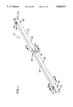
- FIG. 1 is a perspective view of a utility line support structure according to the present invention
- FIG. 2 is a cross-sectional view of FIG. 1 as viewed from section 2--2;
- FIG. 3 is a cross-sectional view of FIG. 1 as viewed from section 3--3;
- FIG. 4 is a cross-sectional view of a bushing assembly according to the present invention as viewed from section 4--4 of FIG. 2;
- FIG. 5 is an inside view of an end cap according to the present invention.
- FIG. 6 is a perspective view of a first embodiment of a tangent crossarm according to the present invention.
- FIG. 7 is a perspective view of a second embodiment of a tangent crossarm according to the present invention.
- FIG. 8 is a perspective view of a third embodiment of a tangent crossarm according to the present invention.
- FIG. 9 is a perspective view of a first embodiment of a deadend according to the present invention.
- FIG. 10 is a perspective view of a second embodiment of a deadend according to the present invention.
- FIG. 11 is a perspective view of a third embodiment of a deadend according to the present invention.
- FIG. 12 is a perspective view of an adaptor which can be used according to the method of the present invention.
- FIG. 13 is a perspective view of a utility line support pulley connected to a utility pole beam adapted according to the method of the present invention.
- FIG. 14 is a perspective view of an extension arm connected to a utility pole beam adapted according to the method of the present invention.
- FIGS. 1-3 a utility line support structure 10 is shown in FIGS. 1-3.
- Support structure 10 can be used as a tangent crossarm, deadend or any other beam used to support utility lines.
- Support structure 10 includes hollow pultruded beam 20 which has transverse holes 22 extending therethrough. Where beam 20 is of a polygonal cross-section, it is preferable to position holes 22 along the centerline of planar surfaces in order to optimize the stress distribution.
- Bushings 30 are inserted into transverse holes 22 and include hollow inner member 32 and a pair of integral washers 34 arranged on opposite ends of inner member 32 and against outer surface 24 of beam 20.
- Hollow inner member 32 and integral washers 34 cooperate to support an axial load.
- Axial load can be applied by (as shown, for example, in FIG. 6) mounting bolts 60, bolts (not shown) for attaching insulators 62 or other structure attached to a bushing 30 for supporting a utility line.
- the primary purpose for this bushing arrangement is to provide structural support to prevent compression damage to beam 20 as would otherwise occur when bolt 60 is tightly torqued.
- bushings 30 also provide resistance to shear loads.
- shear loads are experienced by mounting bolts 60 due to the weight of utility lines and beam 20 and by bolts attaching insulators 62 due to utility line side loads.
- a deadend configuration such as shown in FIG. 9, shear loads are experienced by mounting bolts 60 due to the horizontal line tension load and by bolts attaching insulators 62 due to utility line weight.
- bushings 30 are used both to mount beam 20 and to support insulators 62, bushings 30 could be used only for one purpose or the other.
- insulator 62 could be mounted to beam 20 with a bracket, or beam 20 could be attached to utility pole 64 with a different mounting mechanism which does not require the use of bushing 30.
- bushings 30 include first member 36 and second member 38, each of which has one of integral washers 34.
- Second member 38 includes smaller diameter hollow section 39 which is inserted into larger diameter hollow section 37 of first member 36. Stop 41 on second member 38 can abut end of larger diameter hollow section 37 of first member 36. However, it is preferable to leave a gap so that there is sufficient "play" to allow internal washers 34 to press against outer surface 24 of beam 20 for sealing purposes when first 36 and second 38 members are pushed together.
- An appropriate adhesive or solvent is preferably applied to the outer surface of smaller diameter hollow section 39 to create a bond between first 36 and second 38 members.
- bushing 30 could be constructed in a variety of other ways, such as using a constant cylindrical section to form inner member 32 and attaching integral washers 34 to opposite ends.
- Both first 36 and second 38 members include a plurality of nibs 40 (best shown in FIG. 4) to biasingly engage transverse hole 22 of beam 20, as shown in FIGS. 2 and 3.
- bushings 30 are plastic molded and protuberances 33 are provided to reduce the complexity and cost of manufacturing.
- Protuberances 33 extend radially inward from hollow inner member 32 to engage a bolt inserted therethrough.
- protuberances 33 on first 36 and second 38 members are of a different height in order to provide a constant diameter for engaging a bolt, and protuberances 33 on first 36 and second 38 members are preferably spaced apart at 45 degree intervals to evenly support the bolt radially.
- concentric hollow sleeve 42 abutting inner wall 26 of beam 20 is optionally provided to create additional axial strength. Addition of hollow sleeve 42 is especially appropriate for mounting bolt applications due to the associated high compression loads.
- Beam 20 is a pultruded part and is manufactured as is commonly known in the pultrusion art. Rovings and mats consisting of glass fibers are pulled through a liquid resin and then through a die having a desired cross-section to impregnate and shape the reinforcing fibers into a cured product having a uniform cross-section. In the preferred embodiment, approximately 320 rovings consisting of approximately 4000 glass fibers each and approximately 32 inches of 1.5 ounce per square foot continuous strand mat are used. A high-performance, unsaturated polyester thermoset resin is used in the preferred embodiment, although it will be understood that other types of resins including vinyl esters, epoxies, phenolics and a variety of thermoplastic resins could also be used.
- beam 20 is of a rectangular cross-section, although a number of other shapes could be employed, including annular, oval or various polygonal shapes.
- Beam 20 is approximately 4.0 inches by 2.0 inches in the preferred embodiment, with a wall thickness of approximately 0.2 inches.
- Inner 28 and outer 29 radiuses at the corners of beam 20 are approximately 0.20 and 0.05 inches respectively, and are designed to provide an efficient distribution of stresses.
- Outer surface 24 of beam 20 is preferably coated with a weather-protective coating to prevent surface degradation from ultraviolet rays.
- a high performance, acrylic-based coating such as is available under the tradename SUNGUARD II, is used. The coating can be applied by spraying or in-line coating techniques.
- Support structure 10 of the preferred embodiment includes bushings 30 both along short 25 and long 27 axes of rectangular cross-section beam 20, as shown in FIGS. 2 and 3.
- Short-axis bushings 74 are preferably used to mount the beam to utility pole 64 and long-axis bushings 75 are preferably used to support insulator 62.
- beam 20 is optimally arranged from a structural strength standpoint with long axis 27 parallel to the direction of the primary load.
- a tangent crossarm 70 as shown, for example, in FIG. 6
- the primary load is downward through insulators 62
- a deadend as shown, for example, in FIG. 9
- the primary load is in a horizontal direction through insulator 62.
- Integral washers 34 of bushings 30 could take on a variety of shapes. However, with a rectangular-shaped beam 20, they preferably extend to side edges 21 of beam 20, as best shown in FIGS. 2 and 3. This takes advantage of the added structural strength provided by sidewalls 23 of beam 20, thus reducing the possibility for a compression failure.
- Utility line support structure 10 can comprise either a tangent crossarm 70 with long axis 27 oriented vertically or a deadend 80 with long axis 27 oriented horizontally.
- FIGS. 6, 7 and 8 First, second and third preferred embodiments of the crossarm configuration are shown in FIGS. 6, 7 and 8 respectively.
- crossarm 70 is attached to utility pole 64 with a single mounting bolt 60 inserted through short-axis bushing 74 at the center of beam 20.
- a majority of the downward load is supported by mounting bolt 60 at center of crossarm 70, and support arms 72 are primarily intended to keep crossarm 70 level.
- An upper end of each support arm 72 is connected to a long-axis bushing 75 and a lower end of each support arm 72 is attached to utility pole 64.
- the configuration of the second preferred embodiment shown in FIG. 7 is substantially identical to that of FIG. 6, except that the upper end of each support arm 72 is connected to a short-axis bushing 74.
- the support arms 72 used in the preferred embodiments are commercially available because they are commonly used to support wood beams. However, it may be preferable to use a more flexible support arm than that typically used in order to avoid support arm failure proximate the crossarm connection due to the increased flexibility of the pultruded beam as compared to wood beams.
- crossarm 70 is mounted to utility pole 64 with two bolts 60 horizontally inserted into two spaced-apart short-axis bushings 74. It will be recognized that three or more mounting bolts 60 and bushings 74 could also be used.
- crossarm 70 is attached to bracket 90 which is in turn connected to utility pole 64.
- Bracket 90 includes vertical plate 92 with mounting bolts 60 extending therethrough and nuts (not shown) threaded onto opposite ends of bolts 60.
- Vertical plate 92 may be welded to bracket 90, but in the preferred embodiment bracket 90 and plate 92 are formed from a single stamping operation.
- FIGS. 9, 10 and 11 show first, second and third preferred embodiments of a deadend configuration.
- Bracket 90 has two horizontal plates 94.
- the plates 94 can be welded, but it may be preferable to attach a U-shaped channel to bracket 90 to form horizontal plates 94. All three configurations use the same bracket 90.
- FIGS. 9-11 depict a modular system for creating deadends 80 of varying strength using the same bracket 90 and an appropriate number of individual deadend beams 82 depending on the strength requirements of the particular application.
- beam 82 is inserted between horizontal plates 94 of bracket 90, and mounting bolts 60 are inserted through plates 94 and short-axis bushings 74.
- Insulators 62 are attached to eyelets 84, better shown in FIGS. 10 and 11.
- Eyelets 84 have a shaft which extends through long-axis bushing 75, and a nut is threaded onto its opposite end.
- FIG. 10 In the second preferred deadend configuration shown in FIG. 10, another individual deadend beam 82 is added on top of the top horizontal plate 94, and mounting bolts 60 extend through short-axis bushings 74 in both individual beams 82 and through both horizontal plates 94.
- Connecting brackets 86 on opposite sides of deadend 80 interconnect beams 82 and thus distribute horizontal loads.
- Bolts extend through connecting brackets 86 and long-axis bushings 75.
- Eyelets 84 are welded to bracket and are for attachment to insulators. It will be recognized that, in the most typical arrangement, insulators will be attached to connecting brackets 86 on only one side (the far side in the Figure) of deadend 80 and that eyelets 84 on opposite side will go unused. Alternatively, connecting brackets without an eyelet can be used on the opposite side in such situations.
- a third individual beam 82 is added below bottom horizontal plate 94.
- mounting bolts 60 extend through short-axis bushings 74 in all three individual beams 82 and through both horizontal plates 94.
- Connecting brackets 86 on opposite sides of deadend 80 interconnect beams 82 to distribute horizontal loads.
- Eyelets 84 for connection with insulators are welded to brackets 86, and in the preferred embodiment include a shaft (not shown) extending through brackets 86 and into bushings 75 of the center beam 82 to provide for alignment.
- a U- or V-shaped bolt which extends through beams 82 and provides an attachment for insulators, could be employed in conjunction with brackets on opposite sides of deadend 80.
- Metal washer 88 preferably is shaped substantially like integral washer 34 of bushing 30 so as to evenly distribute across integral washer 34 the applied load.
- end caps 50 extend over opposite ends of beam 20.
- End caps 50 are plastic molded in the preferred embodiment and an appropriate adhesive 52 (thickness is exaggerated in Figure) is applied to an inner side 54 of peripheral walls 56 of end caps 50 to sealingly secure end caps 50 to outer surface 24 of beam 20.
- a plurality of nibs 58 extending inward from peripheral walls 56 are provided to allow for even distribution of adhesive 52.
- Methacrylate is used as an adhesive in the preferred embodiment, but other appropriate adhesives could be used as well.
- bushings 30 are also designed to prevent moisture from entering beam 20.
- inner surface 35 of integral washers 34 are sealingly secured to outer surface 24 of beam 20.
- Adhesive 52 is preferably applied between inner surface 35 of integral washers 34 and outer surface 24 of beam 20.
- Inner surface 35 of integral washers 34 may include concentric rings 43 disposed to engage outer surface 24 of beam 20 to provide for improved sealing.
- a utility pole beam 100 such as a crossarm or deadend, and an adaptor 110 are provided, as shown in FIGS. 12-14.
- Width A of beam 100 is less than a standard dimension S.
- Adaptor 110 is generally U-shaped and includes two sidewalls 112 which have a total width (2 ⁇ B) which is approximately equal to, and preferably slightly less than, the difference between the standard dimension S and the width A of beam 100.
- the distance between sidewalls C is approximately equal to and preferably slightly greater than width A of beam 100.
- Adaptor 110 is placed onto beam 100 so that sidewalls 112 extend adjacent beam 100, as shown in FIGS. 13 and 14.
- Beam 100 is thereby adapted for use with tooling sized to be compatible with a standard dimension S. Also, when certain tooling is to be used on for example pultruded beams, such as is shown in FIG. 14, adaptor 110 reduces the potential for compression damage.
- A is approximately 2.0 inches
- C is slightly greater than 2.0 inches
- B is approximately 0.75 inches
- S is approximately 3.5 inches.
- the adaptor 110 used in the preferred method of the present invention includes top wall 115 interconnecting sidewalls 112 to give adaptor 110 a generally U-shape.
- Support surface 114 is made to rest on beam 100, but it will be recognized that adaptor 110 could also be placed on beam from the side.
- Adaptor 110 includes an outer metal layer 116 formed around an inner layer 118 preferably made of a soft material such as urethane in order to provide flexibility and slip resistance and to minimize damage to beam 100.
- Adaptor 110 includes indentations 119 on opposite sides of sidewalls 112 to prevent tooling, such as extension arm 120 shown in FIG. 14, from slipping when attached.
- Top surface 113 of adaptor 110 also provides a support for tooling and hardware such as utility line support pulley 130 shown in FIG. 13 and the rectangular support bracket of extension arm 120 as shown in FIG. 14.
Abstract
Description
Claims (26)
Priority Applications (3)
| Application Number | Priority Date | Filing Date | Title |
|---|---|---|---|
| US08/180,651 US5605017A (en) | 1994-01-13 | 1994-01-13 | Pultruded utility line support structure and method |
| PCT/US1995/000523 WO1995019479A1 (en) | 1994-01-13 | 1995-01-13 | Pultruded utility line support structure and method |
| AU15673/95A AU1567395A (en) | 1994-01-13 | 1995-01-13 | Pultruded utility line support structure and method |
Applications Claiming Priority (1)
| Application Number | Priority Date | Filing Date | Title |
|---|---|---|---|
| US08/180,651 US5605017A (en) | 1994-01-13 | 1994-01-13 | Pultruded utility line support structure and method |
Publications (1)
| Publication Number | Publication Date |
|---|---|
| US5605017A true US5605017A (en) | 1997-02-25 |
Family
ID=22661238
Family Applications (1)
| Application Number | Title | Priority Date | Filing Date |
|---|---|---|---|
| US08/180,651 Expired - Lifetime US5605017A (en) | 1994-01-13 | 1994-01-13 | Pultruded utility line support structure and method |
Country Status (3)
| Country | Link |
|---|---|
| US (1) | US5605017A (en) |
| AU (1) | AU1567395A (en) |
| WO (1) | WO1995019479A1 (en) |
Cited By (29)
| Publication number | Priority date | Publication date | Assignee | Title |
|---|---|---|---|---|
| US5775035A (en) * | 1996-12-09 | 1998-07-07 | Papin; Neal | Plastic power pole system |
| WO2000050709A1 (en) * | 1999-02-22 | 2000-08-31 | Rosenbaum James E | Cross arm for utility poles |
| US6229086B1 (en) * | 1999-03-12 | 2001-05-08 | Douglas Blanding | Adapter for mounting multiple circuits to utility poles with a pair of cross-arms using candlestick holders |
| US6347488B1 (en) * | 1999-06-29 | 2002-02-19 | Jeffrey T. Koye | Utility pole cross-arm |
| US6367226B1 (en) * | 1999-05-06 | 2002-04-09 | Petroflex N.A., Inc. | Utility pole crossarm, crossarm assembly, and method of manufacture |
| US6609345B2 (en) * | 1999-05-06 | 2003-08-26 | Petroflex, N.A., Inc. | Structural member and method of manufacturing same |
| US6626406B1 (en) | 2000-10-03 | 2003-09-30 | Ted Olson, Jr. | Utility pole with removable crossarm |
| US6834469B2 (en) | 2001-01-24 | 2004-12-28 | Geotek, Inc. | Utility line support member |
| US6862861B1 (en) * | 2002-09-30 | 2005-03-08 | Bethea Power Products | Utility bracket |
| US7007438B1 (en) * | 2002-09-24 | 2006-03-07 | Brooks Manufacturing Co. | Crossarm systems and methods |
| US20060180723A1 (en) * | 2005-02-01 | 2006-08-17 | The Southern Company | Temporary arm gain and saddle |
| US20080172952A1 (en) * | 2007-01-19 | 2008-07-24 | Thomas & Betts International, Inc. | Arm connection for a structural member |
| US20090126284A1 (en) * | 2007-01-19 | 2009-05-21 | Thomas & Betts International, Inc. | Arm connection for a structural member |
| US20090319235A1 (en) * | 2008-04-17 | 2009-12-24 | Maclean-Fogg Company | Fiberglass Cross Arm And Method Of Selecting Same |
| US20100229493A1 (en) * | 2007-01-19 | 2010-09-16 | Thomas & Betts International, Inc. | Arm connection for a structural member |
| WO2011003137A1 (en) * | 2009-07-06 | 2011-01-13 | Farallon Capital Pty Ltd | An electric line cross-arm |
| CN102061822A (en) * | 2010-11-18 | 2011-05-18 | 河南省电力公司南阳供电公司 | Temporary cross arm for replacing linear cement poles and application method thereof |
| US20140131525A1 (en) * | 2010-08-31 | 2014-05-15 | British Columbia Hydro And Power Authority | Transmission cross arm |
| US20150275504A1 (en) * | 2013-11-18 | 2015-10-01 | PLS Technologies, Inc. | Utility or meter pole top reinforcement method and apparatus |
| US20160208510A1 (en) * | 2014-06-18 | 2016-07-21 | Power Composites, Llc | Composite Structural Support Arm |
| US20170159319A1 (en) * | 2013-11-18 | 2017-06-08 | PLS Technologies, Inc. | Utility or meter pole top reinforcement method and apparatus |
| US9850677B2 (en) * | 2015-08-27 | 2017-12-26 | Austin Cary Bennett | Resilient cross arm assembly |
| WO2018129176A1 (en) * | 2017-01-06 | 2018-07-12 | Valmont Industries, Inc. | Improved cross arm support structure |
| WO2018213123A1 (en) * | 2017-05-15 | 2018-11-22 | Maclean Power, L.L.C. | L-shaped crossarm, related system, and method of assembly |
| US20180334293A1 (en) * | 2017-05-19 | 2018-11-22 | Maclean Power, L.L.C. | Endcap for a crossarm, related system, and method of assembly |
| US20190153742A1 (en) * | 2016-07-07 | 2019-05-23 | Comrod As | Overlying Cross Bar Fastener |
| US10968656B2 (en) * | 2016-10-12 | 2021-04-06 | Geotek, Llc | Support member for supporting electrical power lines |
| WO2023044559A1 (en) * | 2021-09-22 | 2023-03-30 | Rs Technologies Inc. | Brackets for crossarms |
| US11795983B2 (en) * | 2017-06-30 | 2023-10-24 | Zephyros, Inc. | Pultruded telescoping arm device |
Families Citing this family (1)
| Publication number | Priority date | Publication date | Assignee | Title |
|---|---|---|---|---|
| CN106972441B (en) * | 2017-04-25 | 2019-03-05 | 江苏神马电力股份有限公司 | A kind of wire fixing device and compound cross-arm |
Citations (30)
| Publication number | Priority date | Publication date | Assignee | Title |
|---|---|---|---|---|
| US839272A (en) * | 1906-09-24 | 1906-12-25 | Anderson G Crow | Cement pole. |
| US1815598A (en) * | 1929-04-19 | 1931-07-21 | Charles L Stroup | Insulating member for high tension construction |
| US1846682A (en) * | 1930-10-17 | 1932-02-23 | Victor F Hammel | Composite supporting structure |
| US2870793A (en) * | 1955-02-08 | 1959-01-27 | Gar Wood Ind Inc | Supporting members |
| US3268191A (en) * | 1965-09-20 | 1966-08-23 | Chance Co Ab | Clamp mounting structure for crossarms |
| US3509678A (en) * | 1968-12-10 | 1970-05-05 | Joslyn Mfg & Supply Co | Apparatus for supporting electrical components and method of making the same |
| US3555747A (en) * | 1969-06-12 | 1971-01-19 | Mif Ind Inc | Lightweight crossarm assemblies |
| US3603717A (en) * | 1970-01-07 | 1971-09-07 | Cp Corp | Crossarm assembly |
| US3649740A (en) * | 1967-11-09 | 1972-03-14 | John R Boyer | Pole-top structure for electric distribution lines |
| US3653622A (en) * | 1970-04-20 | 1972-04-04 | Aluma Form Inc | Nonlineal crossarm for bracketing electrical devices |
| US3715460A (en) * | 1971-06-11 | 1973-02-06 | Detroit Edison Co | Tubular deadend supports |
| US3813837A (en) * | 1972-10-16 | 1974-06-04 | Cascade Pole Co | Fiberglass pole and method and apparatus for fabricating same |
| US3884442A (en) * | 1974-09-30 | 1975-05-20 | Hopeman Brothers Inc | Two post insulator support for utility poles |
| US3911548A (en) * | 1974-10-02 | 1975-10-14 | Interpace Corp | Method for replacing existing utility pole without disturbing hardware mounted thereon |
| US4246732A (en) * | 1977-02-27 | 1981-01-27 | Roland Frehner | Pole, in particular for electric lines |
| US4262047A (en) * | 1979-10-30 | 1981-04-14 | Barnett George D | Fiberglass utility pole crossarm |
| US4312162A (en) * | 1979-08-15 | 1982-01-26 | Jonas Medney | Reinforced pole |
| US4435242A (en) * | 1981-11-26 | 1984-03-06 | Bristol Composite Materials Engineering Limited | Elongate structure |
| US4559262A (en) * | 1981-01-21 | 1985-12-17 | Imperial Chemical Industries, Plc | Fibre reinforced compositions and methods for producing such compositions |
| US4682747A (en) * | 1986-04-24 | 1987-07-28 | King Jr Halm C | Utility insulated cross-arm |
| US4728749A (en) * | 1984-09-03 | 1988-03-01 | R.F.D. Consultants Pty. Ltd. | Utility pole assembly |
| US4742661A (en) * | 1986-11-07 | 1988-05-10 | Joslyn Corporation | End fitting for crossarm brace |
| US4803819A (en) * | 1986-11-03 | 1989-02-14 | Frank Kelsey | Utility pole and attachments formed by pultrusion of dielectric insulating plastic, such as glass fiber reinforced resin |
| US4878984A (en) * | 1985-05-28 | 1989-11-07 | Manufacture D'appareillage Electrique De Cahors | Apparatus for forming a filament-wound structure on a cylindrical pole |
| US4939037A (en) * | 1988-03-02 | 1990-07-03 | John E. Freeman | Composite sign post |
| US4981735A (en) * | 1989-09-05 | 1991-01-01 | The United States Of America As Represented By The Secretary Of The Army | Two piece threaded mounting insert with adhesive for use with honeycomb composite |
| US5009734A (en) * | 1987-03-20 | 1991-04-23 | Manufacture D'appareillage Electrique De Cahors | Method of making an insulating support arm for an electric line pole |
| US5013512A (en) * | 1985-02-19 | 1991-05-07 | Malmstroem Sven E | Method of manufacturing an elongated structural member |
| US5093957A (en) * | 1991-07-08 | 1992-03-10 | Atr International, Inc. | Compression fitting for use in a two-sided honeycomb panel |
| US5247774A (en) * | 1990-06-21 | 1993-09-28 | Johnson David W | Tower constructed of pultruded composites |
-
1994
- 1994-01-13 US US08/180,651 patent/US5605017A/en not_active Expired - Lifetime
-
1995
- 1995-01-13 AU AU15673/95A patent/AU1567395A/en not_active Abandoned
- 1995-01-13 WO PCT/US1995/000523 patent/WO1995019479A1/en active Application Filing
Patent Citations (30)
| Publication number | Priority date | Publication date | Assignee | Title |
|---|---|---|---|---|
| US839272A (en) * | 1906-09-24 | 1906-12-25 | Anderson G Crow | Cement pole. |
| US1815598A (en) * | 1929-04-19 | 1931-07-21 | Charles L Stroup | Insulating member for high tension construction |
| US1846682A (en) * | 1930-10-17 | 1932-02-23 | Victor F Hammel | Composite supporting structure |
| US2870793A (en) * | 1955-02-08 | 1959-01-27 | Gar Wood Ind Inc | Supporting members |
| US3268191A (en) * | 1965-09-20 | 1966-08-23 | Chance Co Ab | Clamp mounting structure for crossarms |
| US3649740A (en) * | 1967-11-09 | 1972-03-14 | John R Boyer | Pole-top structure for electric distribution lines |
| US3509678A (en) * | 1968-12-10 | 1970-05-05 | Joslyn Mfg & Supply Co | Apparatus for supporting electrical components and method of making the same |
| US3555747A (en) * | 1969-06-12 | 1971-01-19 | Mif Ind Inc | Lightweight crossarm assemblies |
| US3603717A (en) * | 1970-01-07 | 1971-09-07 | Cp Corp | Crossarm assembly |
| US3653622A (en) * | 1970-04-20 | 1972-04-04 | Aluma Form Inc | Nonlineal crossarm for bracketing electrical devices |
| US3715460A (en) * | 1971-06-11 | 1973-02-06 | Detroit Edison Co | Tubular deadend supports |
| US3813837A (en) * | 1972-10-16 | 1974-06-04 | Cascade Pole Co | Fiberglass pole and method and apparatus for fabricating same |
| US3884442A (en) * | 1974-09-30 | 1975-05-20 | Hopeman Brothers Inc | Two post insulator support for utility poles |
| US3911548A (en) * | 1974-10-02 | 1975-10-14 | Interpace Corp | Method for replacing existing utility pole without disturbing hardware mounted thereon |
| US4246732A (en) * | 1977-02-27 | 1981-01-27 | Roland Frehner | Pole, in particular for electric lines |
| US4312162A (en) * | 1979-08-15 | 1982-01-26 | Jonas Medney | Reinforced pole |
| US4262047A (en) * | 1979-10-30 | 1981-04-14 | Barnett George D | Fiberglass utility pole crossarm |
| US4559262A (en) * | 1981-01-21 | 1985-12-17 | Imperial Chemical Industries, Plc | Fibre reinforced compositions and methods for producing such compositions |
| US4435242A (en) * | 1981-11-26 | 1984-03-06 | Bristol Composite Materials Engineering Limited | Elongate structure |
| US4728749A (en) * | 1984-09-03 | 1988-03-01 | R.F.D. Consultants Pty. Ltd. | Utility pole assembly |
| US5013512A (en) * | 1985-02-19 | 1991-05-07 | Malmstroem Sven E | Method of manufacturing an elongated structural member |
| US4878984A (en) * | 1985-05-28 | 1989-11-07 | Manufacture D'appareillage Electrique De Cahors | Apparatus for forming a filament-wound structure on a cylindrical pole |
| US4682747A (en) * | 1986-04-24 | 1987-07-28 | King Jr Halm C | Utility insulated cross-arm |
| US4803819A (en) * | 1986-11-03 | 1989-02-14 | Frank Kelsey | Utility pole and attachments formed by pultrusion of dielectric insulating plastic, such as glass fiber reinforced resin |
| US4742661A (en) * | 1986-11-07 | 1988-05-10 | Joslyn Corporation | End fitting for crossarm brace |
| US5009734A (en) * | 1987-03-20 | 1991-04-23 | Manufacture D'appareillage Electrique De Cahors | Method of making an insulating support arm for an electric line pole |
| US4939037A (en) * | 1988-03-02 | 1990-07-03 | John E. Freeman | Composite sign post |
| US4981735A (en) * | 1989-09-05 | 1991-01-01 | The United States Of America As Represented By The Secretary Of The Army | Two piece threaded mounting insert with adhesive for use with honeycomb composite |
| US5247774A (en) * | 1990-06-21 | 1993-09-28 | Johnson David W | Tower constructed of pultruded composites |
| US5093957A (en) * | 1991-07-08 | 1992-03-10 | Atr International, Inc. | Compression fitting for use in a two-sided honeycomb panel |
Non-Patent Citations (6)
| Title |
|---|
| Exhibit A: 1 picture of a foam filled pultruded beam which was in public use in Apr. 1993. * |
| Exhibit A: 1 picture of a foam-filled pultruded beam which was in public use in Apr. 1993. |
| Exhibit B: 1 picture of hollow pultruded beams and mounting brackets in public use in Apr. 1993. * |
| Exhibit C: 1 picture of mounting brackets in public use in Apr. 1993. * |
| Exhibit D: 4 pictures of a hollow pultruded beam having hollow inner support members for receiving a bolt, which was in public use prior to the filing of this application. * |
| Exhibit E: 2 pictures of an end cap for a hollow pultruded beam, which was in public use prior to the filing of this application. * |
Cited By (42)
| Publication number | Priority date | Publication date | Assignee | Title |
|---|---|---|---|---|
| US5775035A (en) * | 1996-12-09 | 1998-07-07 | Papin; Neal | Plastic power pole system |
| WO2000050709A1 (en) * | 1999-02-22 | 2000-08-31 | Rosenbaum James E | Cross arm for utility poles |
| US6229086B1 (en) * | 1999-03-12 | 2001-05-08 | Douglas Blanding | Adapter for mounting multiple circuits to utility poles with a pair of cross-arms using candlestick holders |
| US6367226B1 (en) * | 1999-05-06 | 2002-04-09 | Petroflex N.A., Inc. | Utility pole crossarm, crossarm assembly, and method of manufacture |
| US6609345B2 (en) * | 1999-05-06 | 2003-08-26 | Petroflex, N.A., Inc. | Structural member and method of manufacturing same |
| US6347488B1 (en) * | 1999-06-29 | 2002-02-19 | Jeffrey T. Koye | Utility pole cross-arm |
| US6626406B1 (en) | 2000-10-03 | 2003-09-30 | Ted Olson, Jr. | Utility pole with removable crossarm |
| US6834469B2 (en) | 2001-01-24 | 2004-12-28 | Geotek, Inc. | Utility line support member |
| US7007438B1 (en) * | 2002-09-24 | 2006-03-07 | Brooks Manufacturing Co. | Crossarm systems and methods |
| US6862861B1 (en) * | 2002-09-30 | 2005-03-08 | Bethea Power Products | Utility bracket |
| US20060180723A1 (en) * | 2005-02-01 | 2006-08-17 | The Southern Company | Temporary arm gain and saddle |
| US7578488B2 (en) * | 2005-02-01 | 2009-08-25 | The Southern Company | Temporary arm gain and saddle |
| US20090308021A1 (en) * | 2005-02-01 | 2009-12-17 | The Southern Company | Temporary Arm Gain and Saddle |
| US8171695B2 (en) | 2007-01-19 | 2012-05-08 | Thomas & Butts International, Inc. | Arm connection for a structural member |
| US20090126284A1 (en) * | 2007-01-19 | 2009-05-21 | Thomas & Betts International, Inc. | Arm connection for a structural member |
| US7685791B2 (en) | 2007-01-19 | 2010-03-30 | Thomas & Betts International, Inc. | Arm connection for a structural member |
| US20100229493A1 (en) * | 2007-01-19 | 2010-09-16 | Thomas & Betts International, Inc. | Arm connection for a structural member |
| US20080172952A1 (en) * | 2007-01-19 | 2008-07-24 | Thomas & Betts International, Inc. | Arm connection for a structural member |
| US20090319235A1 (en) * | 2008-04-17 | 2009-12-24 | Maclean-Fogg Company | Fiberglass Cross Arm And Method Of Selecting Same |
| WO2011003137A1 (en) * | 2009-07-06 | 2011-01-13 | Farallon Capital Pty Ltd | An electric line cross-arm |
| US20140131525A1 (en) * | 2010-08-31 | 2014-05-15 | British Columbia Hydro And Power Authority | Transmission cross arm |
| CN102061822A (en) * | 2010-11-18 | 2011-05-18 | 河南省电力公司南阳供电公司 | Temporary cross arm for replacing linear cement poles and application method thereof |
| CN102061822B (en) * | 2010-11-18 | 2014-12-03 | 国家电网公司 | Temporary cross arm for replacing linear cement poles and application method thereof |
| US20170159319A1 (en) * | 2013-11-18 | 2017-06-08 | PLS Technologies, Inc. | Utility or meter pole top reinforcement method and apparatus |
| US9869108B2 (en) * | 2013-11-18 | 2018-01-16 | PLS Technologies, Inc. | Utility or meter pole top reinforcement method and apparatus |
| US9394716B2 (en) * | 2013-11-18 | 2016-07-19 | PLS Technologies, Inc. | Utility or meter pole top reinforcement method and apparatus |
| US20150275504A1 (en) * | 2013-11-18 | 2015-10-01 | PLS Technologies, Inc. | Utility or meter pole top reinforcement method and apparatus |
| US20170096831A1 (en) * | 2014-06-18 | 2017-04-06 | Power Composites, Llc | Composite Structural Support Arm |
| US9546498B2 (en) * | 2014-06-18 | 2017-01-17 | Power Composites, Llc | Composite structural support arm |
| US9790704B2 (en) * | 2014-06-18 | 2017-10-17 | Power Composites, Llc | Composite structural support arm |
| US20160208510A1 (en) * | 2014-06-18 | 2016-07-21 | Power Composites, Llc | Composite Structural Support Arm |
| US9850677B2 (en) * | 2015-08-27 | 2017-12-26 | Austin Cary Bennett | Resilient cross arm assembly |
| US9859700B2 (en) * | 2015-08-27 | 2018-01-02 | Austin Cary Bennett | Resilient cross arm assembly |
| US20190153742A1 (en) * | 2016-07-07 | 2019-05-23 | Comrod As | Overlying Cross Bar Fastener |
| US10781600B2 (en) * | 2016-07-07 | 2020-09-22 | Comrod As | Overlying cross bar fastener |
| US10968656B2 (en) * | 2016-10-12 | 2021-04-06 | Geotek, Llc | Support member for supporting electrical power lines |
| WO2018129176A1 (en) * | 2017-01-06 | 2018-07-12 | Valmont Industries, Inc. | Improved cross arm support structure |
| WO2018213123A1 (en) * | 2017-05-15 | 2018-11-22 | Maclean Power, L.L.C. | L-shaped crossarm, related system, and method of assembly |
| US11047147B2 (en) | 2017-05-15 | 2021-06-29 | Maclean Power, Llc | L-shaped crossarm, related system, and method of assembly |
| US20180334293A1 (en) * | 2017-05-19 | 2018-11-22 | Maclean Power, L.L.C. | Endcap for a crossarm, related system, and method of assembly |
| US11795983B2 (en) * | 2017-06-30 | 2023-10-24 | Zephyros, Inc. | Pultruded telescoping arm device |
| WO2023044559A1 (en) * | 2021-09-22 | 2023-03-30 | Rs Technologies Inc. | Brackets for crossarms |
Also Published As
| Publication number | Publication date |
|---|---|
| AU1567395A (en) | 1995-08-01 |
| WO1995019479A1 (en) | 1995-07-20 |
Similar Documents
| Publication | Publication Date | Title |
|---|---|---|
| US5605017A (en) | Pultruded utility line support structure and method | |
| US6834469B2 (en) | Utility line support member | |
| JPH05195650A (en) | Electric pole | |
| US6453635B1 (en) | Composite utility poles and methods of manufacture | |
| EP2585748B1 (en) | Cable retention device | |
| US5704185A (en) | Joint for connecting members of a load bearing truss | |
| US5986216A (en) | Reinforced insulator | |
| CN209212028U (en) | A kind of rapid rush-repair tower | |
| US6851247B1 (en) | Composite utility pole core systems | |
| US3291899A (en) | Electric insulators in the form of framed structures incorporating rods of resin bonded fibre | |
| US20230058041A1 (en) | Cable racks for reduced stress and increased load capacity | |
| CA2137659C (en) | Composite insulator | |
| KR101255117B1 (en) | Racks with insulator for low voltage distribution | |
| US20230081859A1 (en) | Substation frame | |
| DE69730329T2 (en) | IMPROVED SUPPORTING STRUCTURES FOR POWER LINES | |
| CN210508616U (en) | Flange and power transformation framework | |
| JPH06101789A (en) | Insulative flange coupling and insulative structure body using the coupling | |
| CN215520258U (en) | Power transmission tower | |
| EP1826882B1 (en) | Insulation cover for a traverse of a pylon | |
| CN112075410B (en) | ADSS optical cable bird repellent device | |
| KR200433441Y1 (en) | Power cable space | |
| CN214543524U (en) | Compound cross arm subassembly and power transmission tower | |
| DE19929078C1 (en) | Device for holding bracket for snow fence, solar cell etc. on roof tile is constituted as load carrying module which transmits all forces from bracket to respective roof laths | |
| CN211046396U (en) | Overhead line's installation fixing device | |
| EP4071324A1 (en) | Composite cross arm and power transmission tower |
Legal Events
| Date | Code | Title | Description |
|---|---|---|---|
| AS | Assignment |
Owner name: PUPI ENTERPRISES L.L.C., MINNESOTA Free format text: ASSIGNMENT OF ASSIGNORS INTEREST;ASSIGNORS:FINGERSON, CONRAD F.;O'BRIEN, WILLIAM J.;REEL/FRAME:007043/0863;SIGNING DATES FROM 19940330 TO 19940404 |
|
| STCF | Information on status: patent grant |
Free format text: PATENTED CASE |
|
| CC | Certificate of correction | ||
| AS | Assignment |
Owner name: GEOTEK, INC., MINNESOTA Free format text: PATENT SECURITY AGREEMENT;ASSIGNOR:PUPI ENTERPRISES, L.L.C.;REEL/FRAME:009314/0580 Effective date: 19980624 |
|
| AS | Assignment |
Owner name: GEOTEK, INC., MINNESOTA Free format text: ASSIGNMENT OF ASSIGNORS INTEREST;ASSIGNOR:PUPI ENTERPRISES, LLC;REEL/FRAME:010731/0748 Effective date: 20000309 |
|
| FPAY | Fee payment |
Year of fee payment: 4 |
|
| FPAY | Fee payment |
Year of fee payment: 8 |
|
| FPAY | Fee payment |
Year of fee payment: 12 |
|
| AS | Assignment |
Owner name: MEDALLION CAPITAL, INC., MINNESOTA Free format text: SECURITY AGREEMENT;ASSIGNOR:GEOTEK ACQUISITION COMPANY, LLC;REEL/FRAME:022203/0907 Effective date: 20090204 |
|
| AS | Assignment |
Owner name: GOETEK ACQUISITION COMPANY LLC, MINNESOTA Free format text: ASSIGNMENT OF ASSIGNORS INTEREST;ASSIGNOR:GEOTEK, INC;REEL/FRAME:022510/0617 Effective date: 20090204 |
|
| AS | Assignment |
Owner name: GEOTEK, LLC, MINNESOTA Free format text: TERMINATION AND RELEASE OF SECURITY;ASSIGNOR:SECURED PARTY MEDALLION CAPITAL, INC.;REEL/FRAME:026234/0786 Effective date: 20101029 |
|
| AS | Assignment |
Owner name: GEOTEK, LLC, MINNESOTA Free format text: CERTIFICATE OF AMENDMENT;ASSIGNOR:GEOTEK ACQUISITION COMPANY, LLC;REEL/FRAME:048288/0913 Effective date: 20100427 |
|
| AS | Assignment |
Owner name: BMO HARRIS BANK N.A., MINNESOTA Free format text: SECURITY INTEREST;ASSIGNOR:GEOTEK, LLC;REEL/FRAME:048478/0581 Effective date: 20190228 |
|
| AS | Assignment |
Owner name: JPMORGAN CHASE BANK, N.A., ILLINOIS Free format text: SECURITY INTEREST;ASSIGNOR:GEOTEK, LLC;REEL/FRAME:061424/0456 Effective date: 20221014 |
|
| AS | Assignment |
Owner name: GEOTEK, LLC, MINNESOTA Free format text: RELEASE BY SECURED PARTY;ASSIGNOR:BMO HARRIS BANK N.A.;REEL/FRAME:061455/0543 Effective date: 20221014 |