US5611516A - Rotary ball valve with retracting seat - Google Patents
Rotary ball valve with retracting seat Download PDFInfo
- Publication number
- US5611516A US5611516A US08/411,338 US41133895A US5611516A US 5611516 A US5611516 A US 5611516A US 41133895 A US41133895 A US 41133895A US 5611516 A US5611516 A US 5611516A
- Authority
- US
- United States
- Prior art keywords
- valve
- ball
- shell
- ports
- seat member
- Prior art date
- Legal status (The legal status is an assumption and is not a legal conclusion. Google has not performed a legal analysis and makes no representation as to the accuracy of the status listed.)
- Expired - Lifetime
Links
Images


Classifications
-
- F—MECHANICAL ENGINEERING; LIGHTING; HEATING; WEAPONS; BLASTING
- F16—ENGINEERING ELEMENTS AND UNITS; GENERAL MEASURES FOR PRODUCING AND MAINTAINING EFFECTIVE FUNCTIONING OF MACHINES OR INSTALLATIONS; THERMAL INSULATION IN GENERAL
- F16K—VALVES; TAPS; COCKS; ACTUATING-FLOATS; DEVICES FOR VENTING OR AERATING
- F16K5/00—Plug valves; Taps or cocks comprising only cut-off apparatus having at least one of the sealing faces shaped as a more or less complete surface of a solid of revolution, the opening and closing movement being predominantly rotary
- F16K5/08—Details
- F16K5/14—Special arrangements for separating the sealing faces or for pressing them together
- F16K5/20—Special arrangements for separating the sealing faces or for pressing them together for plugs with spherical surfaces
- F16K5/201—Special arrangements for separating the sealing faces or for pressing them together for plugs with spherical surfaces with the housing or parts of the housing mechanically pressing the seal against the plug
Definitions
- the invention relates to so-called ball valves wherein a valve member which rotates to control fluid flow through the valve is characterized by a spherical surface which has sealed engagement to an annular seat for the closed condition of the valve.
- the conventional valve member of a ball valve is a full sphere, except for a radial stem and a diametrically extending bore that is transverse to the stem direction.
- the valve-member or ball is actuable by limited rotation, e.g., 90°, about a valve-body axis of stem support, wherein said axis extends through the center of the sphere, intersecting and normal to the axis of the diametrically extending bore.
- the diametrically extending bore aligns with cylindrical inlet and outlet ports or passages in the valve body, and an annular seal such as an elastomeric O-ring retained by one or both of these ports or passages is in peripherally continuous seated and sealing contact with the ball, encircling the adjacent end of the diametrically extending bore of the valve member.
- an annular seal such as an elastomeric O-ring retained by one or both of these ports or passages is in peripherally continuous seated and sealing contact with the ball, encircling the adjacent end of the diametrically extending bore of the valve member.
- the actuating operation of a conventional ball valve is thus characterized by the frictional resistance of the ball-to-seat engagement.
- this friction can be reduced by appropriate choice of seat material and by careful attention to ball sphericity and to the accuracy of ball-stem mounting and rotation.
- seating materials and engagements become sources of friction, wear, and leakage, to the extent that mechanical hysteresis is an on-going operational factor, and repair and maintenance expenses are relatively great.
- U.S. Pat. Nos. 5,228,645 and 5,333,833 disclose ball-valve constructions wherein much of the indicated hysteresis is avoided by utilizing eccentric gyration of the rotary axis of the ball, wherein, for an initially closed condition of the valve, and in its initial phase of actuation, the throw of the eccentric is connected to retract the ball from its seat sufficiently for the ball to clear the seat, prior to a second phase of actuation involving ball rotation to open condition.
- rotary drive of the ball has a lost-motion relation to direct drive of the eccentric.
- the ball In its return stroke from full-open condition, the ball is directly driven in rotation back to a stop at which it has been oriented for its closed condition, and the final phase of eccentric rotation is operative to displace the ball center and thus the ball into contact and ensuing completely sealed engagement with the seat.
- valves of said patents represent an important advance over prior ball-valve constructions, the fact remains that ball rotation is about an eccentrically gyrated axis, however small the eccentric throw; therefore, the final phase of valve closure is necessarily accompanied by a component of eccentric displacement, in the course of establishing sealed closure of the valve.
- Such constructions therefore provide a valve action which is short of a more desirable poppet action in the closing/sealing phase of valve operation.
- Another specific object is to meet the above objects with a construction which features poppet action in the final phase of ball engagement to its seat, for sealed closure of the valve.
- Yet another specific object is to meet the above objects with a construction which is inherently suited to avoiding or very substantially reducing the repair and maintenance expense of handling controlled flows of cryogenic liquids and/or gases.
- the invention achieves these objects in a ball-valve construction (a) wherein the ball surface, which in valve-closed condition must have circumferentially continuous sealed contact with its seat, is mounted for rotation about a fixed axis, and (b) wherein the seat is subjected to axial displacement, into and out of its relation of ball engagement for sealed closure of the valve.
- the axis of such displacement is at all times through the center of the ball and is aligned with inlet and outlet ports of valve-housing structure.
- a rotary cam which may be an eccentric surface, is mounted for rotation about the axis of ball rotation, and the valve seat is guided for its axial displacement pursuant to cam-follower tracking of the throw of the rotary cam or eccentric.
- Various embodiments are disclosed.
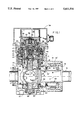
- FIG. 1 is a vertical section through a rotary ball valve of the invention, in almost-closed condition, and taken in the plane defined by the axis of inlet-outlet flow and by the rotary axis of valve actuation;
- FIG. 2 is a simplified and exaggerated section taken in a plane which includes the axis of inlet-outlet flow but is normal to the plane of FIG. 1, and illustrative of a parts relationship for the fully closed condition of the valve, with the valve seat axially displaced into resiliently loaded and sealed closure of the valve;
- FIG. 3 is a view similar to FIG. 2, for the full-open condition of the valve
- FIG. 4 is a graphical layout of an illustrative rotary cam profile, as a function of drive-shaft rotation, with legends to assist in description of such a cam, in operation of the valve of FIGS. 1 to 3;
- FIG. 5 is another graphical layout, to the same scale of drive-shaft rotation as in FIG. 4, with legends to identify discrete events in the coordination of ball rotation with cam-driven seat-displacement, in operation of the valve of FIGS. 1 to 3;
- FIG. 6 is a simplified sectional view of coacting valve parts, for a second embodiment of the invention, in valve-closed condition;
- FIG. 7 is a view of the valve parts of FIG. 6, for the valve-open condition
- FIG. 8 is a view similar to FIG. 7, for the fully open condition of a further-modified valve
- FIG. 9 is a graphical representation of a cam profile for the modified valve of FIG. 8.
- FIG. 10 is a vertical section, in the nature of FIG. 1, for a different drive system in conjunction with valve operation pursuant to FIGS. 6 and 7.
- valve member A in axial-clearance relation with an annular seat member B, all within a generally tubular body C that is closed at its lower end; even though valve member A is shown as a portion of a sphere, it will be sometimes referred to as a ball.
- the valve member or ball A is mounted for rotation about a fixed axis 10 which is central to the tubular portion of body C and which intersects and is normal to a transverse axis 11 of fluid flow from an inlet port 12 to an outlet port 13.
- Local transversely projecting formations 14, 15 of body C are shown fitted with flanged members 16, 17 which respectively define the inlet and outlet ports 12, 13. Flow will be understood to be in either direction between these ports, but for simplified description, the flow controlled by the valve will be referred to as right-to-left, i.e. entry via inlet port 12 and exit via outlet port 13.
- valve member B shall be axially displaceable with respect to the ball A; therefore, valve member B is shown to be guided, at spaced locations along the flow axis 11, via a cylindrical land 18 of body projection 14 and via a cylindrical counterbore 19 of the flanged inlet-port member 16.
- Mechanism to govern axial displacement of the annular seat member B will be later supplied, but for present purposes, it will be explained that a cam-follower part 20 of the seat member is shown to be axially loaded, by spring means in the form of a Belleville element 21, to track via needle-bearing means (22) the rise and fall of a rotary cam or eccentric surface, for which maximum rise and fall dimensions are indicated by labels E max . and E min ., respectively.
- valve member or ball A is mounted for rotational displaceability about the fixed axis 10.
- matched stem or bearing members 24, 24' project from the ball in diametrically opposite directions for coaction with needle-roller bearings 25, 25' in the respective bores of upper and lower cam rings 26, 26'; in turn, the respective cam rings 26, 26' are supported via needle-roller bearings 27, 27' with reference to the valve body C.
- the section plane for ball A in FIG. 1 is determined by the intersecting axes 10, 11, and it will be understood that the spherical surface 30 of ball A preferably extends over a spread of angles about the rotary axis, in either or both directions of rotation away from section plane of axes 10, 11, the spread of angles being at least sufficient to enable the valve-seat seal ring 23 to establish a fully sealed stoppage of fluid flow through the valve for the valve-closed condition. Beyond this spread, there is no need for any further spherical surface area and, therefore, the section of FIG.
- valve member A e.g., a thin somewhat semi-cylindrical shell portion 31, whereby to define a straight cylindrical bore 32 which, in the open condition of the valve has its central axis on the alignment of the inlet/outlet flow axis 11.
- drive torque is provided by a reversible electric motor 34 having a splined output shaft 35 which is centered on the fixed axis 10.
- Motor 34 which may be selected from a wide variety of commercially available varieties, is mounted to an end cap 36 which is in threaded engagement at 37 with a counterbore at the upper end of body C, thus effectively closing an interior volume of the valve body and enabling the motor 34 to be mounted and operated externally of and isolated from exposure to fluids controlled by the valve.
- the end cap 36 is characterized by a central stem 38 within an upwardly open annular cup, for ball-bearing rotary support of the inner driver-magnet component 39 of a magnetic coupling which further comprises an outer driven-magnet component 40 within a downwardly open annular cup formation of the end cap 36;
- the material of end cap 36 is non-magnetic, suitably stainless steel (e.g. CRES 304), and a cladding of the same material is recommended for each of the magnet components 39, 40.
- a lower bearing retainer 42 keyed at 43 to body C, provides central reference for a ball-bearing 44 for rotational support of the lower end or "cup” 41 of a harmonic-drive unit H, which is the means of high-ratio geared reduction and torque enhancement of the magnetically coupled output of motor 34 to the cam set 26, 26'.
- the harmonic-drive unit H is shown to be suitably one of the "cup” variety (Type HDC), namely, a commercial product of Harmonic Drive Technologies, Teijin Seiki Boston, Inc., of Peabody, Mass.
- the intermediate carrier ring 46 provides for bolted suspension of the rigid annular (internally toothed) spline member 47 of the harmonic-drive unit, and a drive-shaft coupling member 48 (to which the driven magnet component 40 is pinned) has ball-bearing stabilization within the upper end of the upper bearing carrier 45.
- the coupling member 48 also has pinned connection to the elliptical-wave generator 49 of the harmonic-drive unit, whereby external teeth of the flexible spline 50 of the harmonic-drive cup 41 are caused to mesh with the rigid teeth of spline member 47 at rotating major-axis regions of the elliptical-wave generator.
- the closed end of the cup 41 has bolted connection to a so-called driver element 51 and to the upper cam ring 26.
- driver element 51 a so-called driver element 51
- the upper cam ring 26 For ruggedly centered rotational stability within the harmonic-drive unit, a pair of opposed angular-contact ball bearings is shown to be adjustably loaded by suitable threaded means, thereby stabilizing on axis 10 the high-speed "drive" of coupling 48 with respect to the greatly reduced low-speed high-torque output of driver element 51 to the upper cam ring 26.
- the annular seat member B has thus far been only generally indicated, for axial displaceability, pursuant to cam-follower tracking at element 20, against a preloading compliance suggested by the compressionally stressed Belleville washer 21.
- Seat member B is further described as comprising an elongate tubular body 28, with a radially outward flange portion 28', which is keyed against rotation about axis 11 and to which the cam-follower element has a threaded fit, so as to retain the seal ring 23.
- the seat member B is further shown to have been preassembled with a sylphon bellows 29, the axially inner end of which is carried by the flange 28 of body 28; the axially outer end of bellows 29 is carried by the radially inward flange of an outer sleeve 29'; by means of which a fixed reference to the valve body C is established upon assembly of the flanged inlet-port member 16 to valve body C.
- bellows 29 will exhibit inherent axial compliance and that in certain cases the compressional stiffness of bellows compliance may be sufficient alone to provide adequate cam-following action even without the Belleville spring action at 21.
- the described bellows provides a highly desirable pressure-equalizing function, thereby facilitating the described axial displaceability of the annular seat member B in the course of operation between valve-opening and valve-closing conditions.
- a ring member 52 bolted to the upper cam ring 26, is shown with an angularly localized cavity 53 for a magnetic component having coaction with external means (not shown) whereby to provide a magnetically generated electrical signal indication of the instantaneous angular position of the valve member or ball A.
- a signal will be understood to be used in electronic feedback control of the excitation of motor 34.
- an inverted cup 54 will be understood to be removably secured over motor 34 and its connection to the drive magnet 39.
- FIGS. 2 to 5 depict an illustrative sequence of valve-opening, commencing in FIG. 2 with the fully closed valve condition, in which annular seat member B is axially loaded by stressed compliant means 21' into peripherally continuous sealed engagement with the spherical surface of the ball A.
- a lost-motion relation exists between rotation of the cam rings 26 (26'). This lost-motion is schematically shown to be occasioned by a pin 60 carried by the upper cam ring and free of engagement with an arm 61 that forms part of the ball (A) structure; for an assumed valve-opening clockwise rotation of cam 26 in FIG.
- pin 60 will contact and drive ball A (via arm 61) in rotary clockwise displacement, only after an initial phase of purely cam rotation, i.e., independent of any ball displacement, it being understood that means such as a torsionally stressed spring (not shown, but as described at 88 and at 90, 90' in FIG. 10) normally urges the ball to its closed position, namely, with arm 61 retained against a stop formation 62 in the valve housing C.
- a torsionally stressed spring normally urges the ball to its closed position, namely, with arm 61 retained against a stop formation 62 in the valve housing C.
- the pin 60 may be a permanent-magnet element, with a degree of magnetically retained engagement to arm 61 with such time, in the return of the valve to its closed condition, as arm 61 is intercepted by stop formation 62, and cam rings 26 (26') are further driven back to the valve-seat closed and sealed position, later to be identified at 66' in FIG. 5.
- cam 26 is shown to have a circular profile which is eccentric (to the greatly exaggerated extent E) with respect to the fixed axis 10 of rotation of both ball A and cam ring 26; and the cam-follower means 20 for seat-member tracking of the cam (26) profile is shown in FIG. 2, to be at the low point of the utilized range of profile displacement, for an assumed 90 degrees of cam (26) rotation to arrive at the full-open condition shown in FIG. 3.
- the orientation of the transverse bore 32 of ball A is angularly displaced through an acute angle, while the cam-following (20) displacement of the annular seat member B has undergone an axial displacement ⁇ .
- FIG. 4 depicts the sinusoidal course of cam-following displacement to be expected for tracking a circular cam profile of gyrated eccentricity E.
- dashed outline 63 a full half cycle is shown; but it is also shown in solid outline 64 that it is preferred to generate cam-following action over a 90-degree range which straddles an inflection point of the sinusoid.
- This preferred range is indicated by legend to be the substantially linear portion of the eccentrically gyrated profile, with inflection at the half-way point (45°) in the 90° range.
- this substantially linear portion is drawn as a linear course 65 wherein, for illustrative purposes only, certain sequential events take place in the first 25° of cam (26) rotation, and wherein numerical indications of seat displacement can be taken to be in millimeters, or in other units, as appropriate to the dimensional scale of the valve.
- cam (26) rotation illustratively begins about 25 degrees prior to pin (60) pick-up of ball arm 61, and it is indicated by legend that there is a clearance between cam 26 and cam follower 20.
- a first increment ⁇ 1 of cam (26) rotation is devoted to take-up of this clearance.
- the next increment ⁇ 2 of cam (26) rotation is concerned with take-up of mechanical play (including compliant compression of the sealed seat-to-ball engagement).
- the third increment of cam (26) rotation is concerned with axially displacing seat member B into clearance relation with ball A.
- cam/cam-follower coaction establishes the clearance and preloaded-seal events noted above in connection with the symbols ⁇ 2 , ⁇ 3 .
- a heavy arrow 66' at the zero-degrees position in FIG. 5 will be understood to indicate that a control switch coaction between cam 26 and body C is operative to shut down the excitation of motor 34 upon valve-closing return of cam 26 to this zero-degree condition.
- FIGS. 6 and 7 respectively depict "closed” and “open” conditions of a modified valve wherein the ball A' is but a limited sector of a “hollow” sphere or spherical shell, again mounted to be rotatable about the fixed axis 10, and wherein drive to a cam 26 is responsible for correctly phased clearance of the annular seat member B' from ball A' to permits if desired, a full 90° of ball A' rotation, all in the manner described in detail for the valve-member (a) and valve-seat (b) operation of FIGS. 1 to 5.
- outlet 13 is shown additionally to comprise a fixed tubular extension 13', projecting inwardly into the volume of the geometric sphere of "ball" A' but without interference with ball-A' displacement.
- cam 26 is not shown in FIGS. 6 and 7, it will be understood to have been suggested by the designation of its eccentricity E', which accounts, again with exaggeration, for the clearance of the seat seal 23 with respect to the locus or path of spherical displacement of ball A', throughout the course of rotary-ball displacement.
- FIGS. 8 and 9 represents modification of the embodiment of FIGS. 6 and 7, and therefore the same reference designations are used, as appropriate.
- the point of difference in FIGS. 8 and 9 is that the cam profile of FIG. 9, for assured clearance of the annular seat member B' with respect to ball A', is non-circular but is characterized by a land or rise 67 to maintain the clearance ⁇ 3 throughout all 90 degrees of rotation of "ball" A', should that much ball rotation be necessary.
- the shut-off switching means 66 of FIG. 3 will have been omitted, thus enabling further cam rotation A to a point symbolized at 68 in FIG.
- FIG. 10 is illustrative of the use of a brushless d-c servo motor as the driver for rotation of a ball-valve member A' about axis 10, in generally the configuration schematically depicted and described in connection with FIGS. 6 and 7.
- the valve member A' will be understood to be a limited sector of a spherical shell 70, journalled for anti-friction rotation in upper and lower bearings 25, 25', coaxially within the upper and lower cams 26, 26' which impart axial displacement to the valve-seat member B'.
- the connecting member 33 which ties the upper and lower cams to each other is not shown in FIG. 10 but will be understood to be out of the plane of the drawing of FIG. 10.
- an elongate tubular extension 13' of the outlet 13 projects inwardly of the valve, on axis 11 and past the point of intersection with the rotary axis 10, into close clearance relation with the concave spherical back surface of the shell of the ball valve member A'.
- the cam-connecting member (33) will be understood to be in approach to its maximum angular offset (e.g. 25 degrees or less) from abutment with shell 70; and for the full-open condition (e.g. as in FIG. 7), the cam-connecting member (33) will be in abutment with shell 70 (as for the case of pin 60 abutment with ball arm 61 in FIG.
- the drive motor in FIG. 10 is a brushless d-c servo motor, brushless being indicated to avoid reliance on mechanical brushes sliding on a commutator; instead, multiple windings in the stator are commutated by semiconductor power switches.
- Suitable brushless motors of the character indicated are commercially available from a plurality of sources, including Sierracin/Magnedyne of Carlsbad, Calif., and Magnetic Technology Division of Vernitron Corporation, Canoga Park, Calif., so that extensive description is not needed for present purposes. Suffice it to say that the motor of FIG. 10 preferably employs three winding phases, in a 12-pole configuration. Furthermore, reference is made to said U.S.
- stator of the motor comprises windings 75 and a stack 76 of laminations; electrical leads, as at 77, to the windings are supplied via a standard multiple-pin external-connection fitting 78.
- the stator components are sealed inside an annular space defined by and between the housing C' and a housing base member 79 and its skirt 80; such sealed confinement forecloses stator components from exposure to effluent-gas and ambient environments.
- the rotor 81 including shaft 74, consists of a core 82, back-up iron 83, and permanent magnets 84, retained by annular end pieces 85 which, with an outer cylindrical cladding or shell 86, complete the sealed containment and protection of the magnets 84 from effluent-gas exposure.
- the thus-sealed stator and rotor assemblies provide a so-called "wetted construction", allowing effluent to enter and pressurize the rotor cavity of the motor. And since it is not necessary to seal the motor drive shaft 74, no dynamic seals need be used at any of the sites of rotary-bearing support.
- a wound and tensed clock spring 88 is secured at its inner end to shaft 74, with outer-end anchorage by bolt 89 to the flanged base member 79.
- further upper and lower clock springs 90, 90' are shown for reaction between ball A' and the respective upper and lower cams 26, 26'.
- the direction of torsional bias by spring 88 assures preload of shaft 74 in the angular direction of "failing safe" to a closed and sealed condition of the valve.
Abstract
Description
Claims (7)
Priority Applications (1)
| Application Number | Priority Date | Filing Date | Title |
|---|---|---|---|
| US08/411,338 US5611516A (en) | 1995-03-27 | 1995-03-27 | Rotary ball valve with retracting seat |
Applications Claiming Priority (1)
| Application Number | Priority Date | Filing Date | Title |
|---|---|---|---|
| US08/411,338 US5611516A (en) | 1995-03-27 | 1995-03-27 | Rotary ball valve with retracting seat |
Publications (1)
| Publication Number | Publication Date |
|---|---|
| US5611516A true US5611516A (en) | 1997-03-18 |
Family
ID=23628524
Family Applications (1)
| Application Number | Title | Priority Date | Filing Date |
|---|---|---|---|
| US08/411,338 Expired - Lifetime US5611516A (en) | 1995-03-27 | 1995-03-27 | Rotary ball valve with retracting seat |
Country Status (1)
| Country | Link |
|---|---|
| US (1) | US5611516A (en) |
Cited By (22)
| Publication number | Priority date | Publication date | Assignee | Title |
|---|---|---|---|---|
| US6026845A (en) * | 1996-04-24 | 2000-02-22 | Bighorn Valve, Inc. | Flow, split Venturi, axially-rotated valve |
| WO2001033125A1 (en) * | 1999-10-29 | 2001-05-10 | Russell Larry R | Quarter-turn rotary plug valve with seats reciprocable during operation |
| US20030193036A1 (en) * | 2002-04-12 | 2003-10-16 | Jeff Mike | Top-entry ball valve assembly having camming surfaces |
| US20030213432A1 (en) * | 2002-03-29 | 2003-11-20 | Parent Donald G. | Gravity-fed in-line continuous processing system and method |
| US20040094410A1 (en) * | 2000-01-12 | 2004-05-20 | Parent Donald G. | System for coating insulative substrates |
| US20050211942A1 (en) * | 2002-03-19 | 2005-09-29 | Fisher Controls International Llc | Fluid flow control valve with high temperature bi-directional shutoff |
| US20050269545A1 (en) * | 2004-04-28 | 2005-12-08 | Yasuhiro Chiba | Eccentric type rotary valve |
| US20080103632A1 (en) * | 2006-10-27 | 2008-05-01 | Direct Drive Systems, Inc. | Electromechanical energy conversion systems |
| US20100019601A1 (en) * | 2008-07-28 | 2010-01-28 | Direct Drive Systems, Inc. | Wrapped rotor sleeve for an electric machine |
| US7677261B1 (en) | 2001-10-29 | 2010-03-16 | Big Horn Valve, Inc. | High flow, low mobile weight quick disconnect system |
| US20110266484A1 (en) * | 2010-04-30 | 2011-11-03 | Fisher Controls International Llc | Floating Ball Valve Seal With Bellows and C-Seal |
| CN103375602A (en) * | 2012-04-12 | 2013-10-30 | 上海浦东汉威阀门有限公司 | Open valve seat type ball valve |
| US20140319395A1 (en) * | 2013-04-26 | 2014-10-30 | Flowserve Management Company | Seal carriers for ball valves, ball valve assemblies including such seal carriers, and related methods |
| US20150137018A1 (en) * | 2013-11-19 | 2015-05-21 | Larry Rayner Russell | Quarter turn ball valve with lift-off seats |
| US20160245411A1 (en) * | 2015-02-25 | 2016-08-25 | Elkhart Brass Manufacturing Company, Inc. | Valve |
| US20170067566A1 (en) * | 2015-09-06 | 2017-03-09 | Gimpel USA Inc. | Fluid Valve |
| US20190101218A1 (en) * | 2017-10-04 | 2019-04-04 | GM Global Technology Operations LLC | Ball valve geometry and dynamic seal assembly |
| CN112664697A (en) * | 2020-12-30 | 2021-04-16 | 俞柔冰 | Main gas valve device for gas stove |
| US11519509B2 (en) | 2020-02-14 | 2022-12-06 | Crane Chempharma & Energy Corp. | Valve with unobstructed flow path having increased flow coefficient |
| US11841089B2 (en) * | 2020-02-14 | 2023-12-12 | Crane Chempharma & Energy Corp. | Valve with unobstructed flow path having increased flow coefficient |
| US11946557B2 (en) * | 2020-02-14 | 2024-04-02 | Crane Chempharma & Energy Corp. | Valve with unobstructed flow path having increased flow coefficient |
| US11953113B2 (en) * | 2020-02-14 | 2024-04-09 | Crane Chempharma & Energy Corp. | Valve with unobstructed flow path having increased flow coefficient |
Citations (8)
| Publication number | Priority date | Publication date | Assignee | Title |
|---|---|---|---|---|
| US3007490A (en) * | 1958-06-26 | 1961-11-07 | Allis Chalmers Mfg Co | Rotary valve control |
| US3245653A (en) * | 1962-05-01 | 1966-04-12 | Gen Dynamics Corp | Trunnion mounted ball valve having lost motion and positive reduction actuating means |
| US3404864A (en) * | 1966-12-27 | 1968-10-08 | Robert R. Reddy | Rotary valve with concave seating surface |
| US3830693A (en) * | 1971-06-18 | 1974-08-20 | Krupp Gmbh | Gate for circulation control in nuclear reactor using circulating fuel-element balls |
| US4676480A (en) * | 1985-01-11 | 1987-06-30 | Societe Anonyme: Societe Europeenne De Propulsion | Ball valve |
| US5228645A (en) * | 1992-04-13 | 1993-07-20 | Marotta Scientific Controls, Inc. | Rotary ball valve with lifting ball |
| US5247964A (en) * | 1991-03-15 | 1993-09-28 | Societe Europeenne De Propulsion | Valve with redundancy on closing |
| US5333833A (en) * | 1992-04-13 | 1994-08-02 | Marotta Scientific Controls, Inc. | Rotary ball valve with lifting ball |
-
1995
- 1995-03-27 US US08/411,338 patent/US5611516A/en not_active Expired - Lifetime
Patent Citations (8)
| Publication number | Priority date | Publication date | Assignee | Title |
|---|---|---|---|---|
| US3007490A (en) * | 1958-06-26 | 1961-11-07 | Allis Chalmers Mfg Co | Rotary valve control |
| US3245653A (en) * | 1962-05-01 | 1966-04-12 | Gen Dynamics Corp | Trunnion mounted ball valve having lost motion and positive reduction actuating means |
| US3404864A (en) * | 1966-12-27 | 1968-10-08 | Robert R. Reddy | Rotary valve with concave seating surface |
| US3830693A (en) * | 1971-06-18 | 1974-08-20 | Krupp Gmbh | Gate for circulation control in nuclear reactor using circulating fuel-element balls |
| US4676480A (en) * | 1985-01-11 | 1987-06-30 | Societe Anonyme: Societe Europeenne De Propulsion | Ball valve |
| US5247964A (en) * | 1991-03-15 | 1993-09-28 | Societe Europeenne De Propulsion | Valve with redundancy on closing |
| US5228645A (en) * | 1992-04-13 | 1993-07-20 | Marotta Scientific Controls, Inc. | Rotary ball valve with lifting ball |
| US5333833A (en) * | 1992-04-13 | 1994-08-02 | Marotta Scientific Controls, Inc. | Rotary ball valve with lifting ball |
Cited By (62)
| Publication number | Priority date | Publication date | Assignee | Title |
|---|---|---|---|---|
| US6026845A (en) * | 1996-04-24 | 2000-02-22 | Bighorn Valve, Inc. | Flow, split Venturi, axially-rotated valve |
| WO2001033125A1 (en) * | 1999-10-29 | 2001-05-10 | Russell Larry R | Quarter-turn rotary plug valve with seats reciprocable during operation |
| US6378841B1 (en) | 1999-10-29 | 2002-04-30 | Larry R. Russell | Quarter-turn rotary plug valve with seats reciprocable during operation |
| GB2372551A (en) * | 1999-10-29 | 2002-08-28 | Larry Rayner Russell | Quarter-turn rotary plug valve with seats reciprocable during operation |
| GB2372551B (en) * | 1999-10-29 | 2003-12-31 | Larry Rayner Russell | Quarter-turn rotary plug valve with seats reciprocable during operation |
| US20040094410A1 (en) * | 2000-01-12 | 2004-05-20 | Parent Donald G. | System for coating insulative substrates |
| US7677261B1 (en) | 2001-10-29 | 2010-03-16 | Big Horn Valve, Inc. | High flow, low mobile weight quick disconnect system |
| US20050211942A1 (en) * | 2002-03-19 | 2005-09-29 | Fisher Controls International Llc | Fluid flow control valve with high temperature bi-directional shutoff |
| US7484710B2 (en) * | 2002-03-19 | 2009-02-03 | Fisher Controls International Llc | Fluid flow control valve with high temperature bi-directional shutoff |
| US20060283391A1 (en) * | 2002-03-29 | 2006-12-21 | Parent Donald G | Gravity-fed in-line continuous processing system and method |
| US6983925B2 (en) * | 2002-03-29 | 2006-01-10 | D2 In-Line Solutions, Llc | Rotary barrel gate valve |
| US20060251814A1 (en) * | 2002-03-29 | 2006-11-09 | Parent Donald G | Gravity-fed in-line continuous processing system and method |
| US20050058776A1 (en) * | 2002-03-29 | 2005-03-17 | Parent Donald G. | Gravity-fed in-line continuous processing system and method |
| US20030213929A1 (en) * | 2002-03-29 | 2003-11-20 | Parent Donald G. | Rotary barrel gate valve |
| US20030213432A1 (en) * | 2002-03-29 | 2003-11-20 | Parent Donald G. | Gravity-fed in-line continuous processing system and method |
| US20030193036A1 (en) * | 2002-04-12 | 2003-10-16 | Jeff Mike | Top-entry ball valve assembly having camming surfaces |
| US6681793B2 (en) * | 2002-04-12 | 2004-01-27 | Jeff Mike | Top-entry ball valve assembly having camming surfaces |
| US20050269545A1 (en) * | 2004-04-28 | 2005-12-08 | Yasuhiro Chiba | Eccentric type rotary valve |
| CN101107466B (en) * | 2005-02-28 | 2011-03-23 | 费希尔控制产品国际有限公司 | Fluid flow control valve with high temperature bi-directional shutoff |
| JP2008531950A (en) * | 2005-02-28 | 2008-08-14 | フィッシャー コントロールズ インターナショナル リミテッド ライアビリティー カンパニー | Fluid control valve with bidirectional shut-off function for high temperatures |
| US7710081B2 (en) | 2006-10-27 | 2010-05-04 | Direct Drive Systems, Inc. | Electromechanical energy conversion systems |
| US20080103632A1 (en) * | 2006-10-27 | 2008-05-01 | Direct Drive Systems, Inc. | Electromechanical energy conversion systems |
| US7960948B2 (en) | 2006-10-27 | 2011-06-14 | Direct Drive Systems, Inc. | Electromechanical energy conversion systems |
| US8310123B2 (en) | 2008-07-28 | 2012-11-13 | Direct Drive Systems, Inc. | Wrapped rotor sleeve for an electric machine |
| US8237320B2 (en) | 2008-07-28 | 2012-08-07 | Direct Drive Systems, Inc. | Thermally matched composite sleeve |
| US20100019600A1 (en) * | 2008-07-28 | 2010-01-28 | Saban Daniel M | Thermally matched composite sleeve |
| US20100019613A1 (en) * | 2008-07-28 | 2010-01-28 | Direct Drive Systems, Inc. | Stator for an electric machine |
| US20100019603A1 (en) * | 2008-07-28 | 2010-01-28 | Direct Drive Systems, Inc. | Rotor for an electric machine |
| US20100019609A1 (en) * | 2008-07-28 | 2010-01-28 | John Stout | End turn configuration of an electric machine |
| US20100019590A1 (en) * | 2008-07-28 | 2010-01-28 | Direct Drive Systems, Inc. | Electric machine |
| US20100019601A1 (en) * | 2008-07-28 | 2010-01-28 | Direct Drive Systems, Inc. | Wrapped rotor sleeve for an electric machine |
| US20100171383A1 (en) * | 2008-07-28 | 2010-07-08 | Peter Petrov | Rotor for electric machine having a sleeve with segmented layers |
| US20100019610A1 (en) * | 2008-07-28 | 2010-01-28 | Saban Daniel M | Hybrid winding configuration of an electric machine |
| US20100019599A1 (en) * | 2008-07-28 | 2010-01-28 | Direct Drive Systems, Inc. | Rotor for an electric machine |
| US8040007B2 (en) | 2008-07-28 | 2011-10-18 | Direct Drive Systems, Inc. | Rotor for electric machine having a sleeve with segmented layers |
| US20100019589A1 (en) * | 2008-07-28 | 2010-01-28 | Saban Daniel M | Slot configuration of an electric machine |
| US8415854B2 (en) | 2008-07-28 | 2013-04-09 | Direct Drive Systems, Inc. | Stator for an electric machine |
| US8183734B2 (en) | 2008-07-28 | 2012-05-22 | Direct Drive Systems, Inc. | Hybrid winding configuration of an electric machine |
| US8421297B2 (en) | 2008-07-28 | 2013-04-16 | Direct Drive Systems, Inc. | Stator wedge for an electric machine |
| US8247938B2 (en) | 2008-07-28 | 2012-08-21 | Direct Drive Systems, Inc. | Rotor for electric machine having a sleeve with segmented layers |
| US8253298B2 (en) | 2008-07-28 | 2012-08-28 | Direct Drive Systems, Inc. | Slot configuration of an electric machine |
| US20100019598A1 (en) * | 2008-07-28 | 2010-01-28 | Direct Drive Systems, Inc. | Rotor for an electric machine |
| US8350432B2 (en) | 2008-07-28 | 2013-01-08 | Direct Drive Systems, Inc. | Electric machine |
| US8179009B2 (en) | 2008-07-28 | 2012-05-15 | Direct Drive Systems, Inc. | Rotor for an electric machine |
| US8496226B2 (en) * | 2010-04-30 | 2013-07-30 | Fisher Controls International Llc | Floating ball valve seal with bellows and C-seal |
| US20110266484A1 (en) * | 2010-04-30 | 2011-11-03 | Fisher Controls International Llc | Floating Ball Valve Seal With Bellows and C-Seal |
| CN103375602A (en) * | 2012-04-12 | 2013-10-30 | 上海浦东汉威阀门有限公司 | Open valve seat type ball valve |
| US20140319395A1 (en) * | 2013-04-26 | 2014-10-30 | Flowserve Management Company | Seal carriers for ball valves, ball valve assemblies including such seal carriers, and related methods |
| US9816625B2 (en) * | 2013-04-26 | 2017-11-14 | Flowserve Management Company | Seal carriers for ball valves, ball valve assemblies including such seal carriers, and related methods |
| US20150137018A1 (en) * | 2013-11-19 | 2015-05-21 | Larry Rayner Russell | Quarter turn ball valve with lift-off seats |
| US9328827B2 (en) * | 2013-11-19 | 2016-05-03 | Larry Rayner Russell | Quarter turn ball valve with lift-off seats |
| US10100934B2 (en) * | 2015-02-25 | 2018-10-16 | Elkhart Brass Manufacturing Company, Inc. | Valve with movable valve seat |
| US20160245411A1 (en) * | 2015-02-25 | 2016-08-25 | Elkhart Brass Manufacturing Company, Inc. | Valve |
| US20170067566A1 (en) * | 2015-09-06 | 2017-03-09 | Gimpel USA Inc. | Fluid Valve |
| US20190101218A1 (en) * | 2017-10-04 | 2019-04-04 | GM Global Technology Operations LLC | Ball valve geometry and dynamic seal assembly |
| US10295066B2 (en) * | 2017-10-04 | 2019-05-21 | GM Global Technology Operations LLC | Ball valve geometry and dynamic seal assembly |
| US11519509B2 (en) | 2020-02-14 | 2022-12-06 | Crane Chempharma & Energy Corp. | Valve with unobstructed flow path having increased flow coefficient |
| US11841089B2 (en) * | 2020-02-14 | 2023-12-12 | Crane Chempharma & Energy Corp. | Valve with unobstructed flow path having increased flow coefficient |
| US11946557B2 (en) * | 2020-02-14 | 2024-04-02 | Crane Chempharma & Energy Corp. | Valve with unobstructed flow path having increased flow coefficient |
| US11953113B2 (en) * | 2020-02-14 | 2024-04-09 | Crane Chempharma & Energy Corp. | Valve with unobstructed flow path having increased flow coefficient |
| CN112664697A (en) * | 2020-12-30 | 2021-04-16 | 俞柔冰 | Main gas valve device for gas stove |
| CN112664697B (en) * | 2020-12-30 | 2023-10-10 | 俞柔冰 | Main gas valve device for gas stove |
Similar Documents
| Publication | Publication Date | Title |
|---|---|---|
| US5611516A (en) | Rotary ball valve with retracting seat | |
| CA1118399A (en) | Magnetically actuated rising stem valve | |
| US4671486A (en) | Magnetic valve actuator | |
| CA1115258A (en) | Magnetically actuated stopper valve | |
| EP2391839B1 (en) | Axial flow control valves having an internal actuator | |
| JPH0364749B2 (en) | ||
| JP2788424B2 (en) | Leakless magnetic power transmission valve | |
| JP2001221359A (en) | Hermetically sealed motor driven valve | |
| US3675894A (en) | Eyelid hybrid butterfly type poppet valve | |
| CN100523573C (en) | Straight flow reversing valve | |
| JPH02292583A (en) | Electrically driven control valve | |
| US20100140521A1 (en) | Stemless ball valve | |
| US5333833A (en) | Rotary ball valve with lifting ball | |
| KR20200013654A (en) | Three-way valve for flow control and temperature control device using the same | |
| US20140021384A1 (en) | Electronically controlled valve assembly | |
| US3591127A (en) | Butterfly valve structure with combined translation and rotary movements | |
| EP0147950A3 (en) | Ball valve | |
| US7111642B2 (en) | Valve having fast and slow acting closure elements | |
| US4382578A (en) | Magnetically actuated rising stem valve | |
| US5228645A (en) | Rotary ball valve with lifting ball | |
| JPH06213212A (en) | Actuator | |
| US3531075A (en) | Butterfly valve | |
| JPH02223349A (en) | Linear driving assembly | |
| JP3110000B2 (en) | Rotary valve drive | |
| WO2016099337A1 (en) | Shutoff and control ball valve |
Legal Events
| Date | Code | Title | Description |
|---|---|---|---|
| AS | Assignment |
Owner name: MAROTTA SCIENTIFIC CONTROL, INC., NEW JERSEY Free format text: ASSIGNMENT OF ASSIGNORS INTEREST;ASSIGNORS:REINICKE, ROBERT H.;CARDIN, JOSEPH M.;DALENE, ARNOLD;REEL/FRAME:007425/0805;SIGNING DATES FROM 19950321 TO 19950322 |
|
| STCF | Information on status: patent grant |
Free format text: PATENTED CASE |
|
| CC | Certificate of correction | ||
| FPAY | Fee payment |
Year of fee payment: 4 |
|
| AS | Assignment |
Owner name: MAROTTA CONTROLS, INC., NEW JERSEY Free format text: CHANGE OF NAME;ASSIGNOR:MAROTTA SCIENTIFIC CONTROLS, INC.;REEL/FRAME:014337/0368 Effective date: 20030610 |
|
| FPAY | Fee payment |
Year of fee payment: 8 |
|
| AS | Assignment |
Owner name: PNC BANK, NATIONAL ASSOCIATION, NEW JERSEY Free format text: SECURITY AGREEMENT;ASSIGNOR:MAROTTA CONTROLS, INC.;REEL/FRAME:018120/0363 Effective date: 20060630 |
|
| AS | Assignment |
Owner name: WELLS FARGO BANK, NATIONAL ASSOCIATION, NEW YORK Free format text: SECURITY INTEREST;ASSIGNOR:MAROTTA SCIENTIFIC CONTROLS, INC., N/K/A MAROTTA CONTROLS, INC.;REEL/FRAME:020627/0851 Effective date: 20080306 |
|
| AS | Assignment |
Owner name: MAROTTA CONTROLS, INC., NEW JERSEY Free format text: DISCHARGE OF SECURITY INTEREST;ASSIGNOR:STEEL CITY CAPITAL FUNDING, LLC;REEL/FRAME:020690/0137 Effective date: 20080306 |
|
| FPAY | Fee payment |
Year of fee payment: 12 |