US5623910A - Check and vent valve assembly - Google Patents
Check and vent valve assembly Download PDFInfo
- Publication number
- US5623910A US5623910A US08/347,283 US34728394A US5623910A US 5623910 A US5623910 A US 5623910A US 34728394 A US34728394 A US 34728394A US 5623910 A US5623910 A US 5623910A
- Authority
- US
- United States
- Prior art keywords
- fuel
- pressure
- check valve
- housing
- outlet
- Prior art date
- Legal status (The legal status is an assumption and is not a legal conclusion. Google has not performed a legal analysis and makes no representation as to the accuracy of the status listed.)
- Expired - Lifetime
Links
- 239000000446 fuel Substances 0.000 claims abstract description 248
- 238000011144 upstream manufacturing Methods 0.000 claims abstract description 6
- 230000036316 preload Effects 0.000 claims description 11
- 230000000717 retained effect Effects 0.000 claims description 4
- 239000007788 liquid Substances 0.000 claims 6
- 230000000903 blocking effect Effects 0.000 claims 1
- 230000009977 dual effect Effects 0.000 description 8
- 239000002828 fuel tank Substances 0.000 description 6
- 229920003002 synthetic resin Polymers 0.000 description 6
- 239000000057 synthetic resin Substances 0.000 description 6
- 238000002485 combustion reaction Methods 0.000 description 3
- 230000006835 compression Effects 0.000 description 3
- 238000007906 compression Methods 0.000 description 3
- 230000007257 malfunction Effects 0.000 description 3
- 230000013011 mating Effects 0.000 description 3
- 239000000203 mixture Substances 0.000 description 3
- 230000003071 parasitic effect Effects 0.000 description 3
- 229910001369 Brass Inorganic materials 0.000 description 2
- LFQSCWFLJHTTHZ-UHFFFAOYSA-N Ethanol Chemical compound CCO LFQSCWFLJHTTHZ-UHFFFAOYSA-N 0.000 description 2
- 239000010951 brass Substances 0.000 description 2
- 239000000356 contaminant Substances 0.000 description 2
- 230000006866 deterioration Effects 0.000 description 2
- 239000002283 diesel fuel Substances 0.000 description 2
- 239000003502 gasoline Substances 0.000 description 2
- 229920005989 resin Polymers 0.000 description 2
- 239000011347 resin Substances 0.000 description 2
- 230000004044 response Effects 0.000 description 2
- 230000001133 acceleration Effects 0.000 description 1
- 230000005540 biological transmission Effects 0.000 description 1
- 230000000740 bleeding effect Effects 0.000 description 1
- 230000008859 change Effects 0.000 description 1
- 230000000295 complement effect Effects 0.000 description 1
- 230000007423 decrease Effects 0.000 description 1
- 230000001934 delay Effects 0.000 description 1
- 238000001746 injection moulding Methods 0.000 description 1
- 238000012423 maintenance Methods 0.000 description 1
- 238000004519 manufacturing process Methods 0.000 description 1
- 238000000034 method Methods 0.000 description 1
- 230000002093 peripheral effect Effects 0.000 description 1
- 230000008569 process Effects 0.000 description 1
- 230000003014 reinforcing effect Effects 0.000 description 1
- 230000008439 repair process Effects 0.000 description 1
- 238000007789 sealing Methods 0.000 description 1
- 238000002791 soaking Methods 0.000 description 1
Images


Classifications
-
- F—MECHANICAL ENGINEERING; LIGHTING; HEATING; WEAPONS; BLASTING
- F02—COMBUSTION ENGINES; HOT-GAS OR COMBUSTION-PRODUCT ENGINE PLANTS
- F02M—SUPPLYING COMBUSTION ENGINES IN GENERAL WITH COMBUSTIBLE MIXTURES OR CONSTITUENTS THEREOF
- F02M37/00—Apparatus or systems for feeding liquid fuel from storage containers to carburettors or fuel-injection apparatus; Arrangements for purifying liquid fuel specially adapted for, or arranged on, internal-combustion engines
- F02M37/0011—Constructional details; Manufacturing or assembly of elements of fuel systems; Materials therefor
- F02M37/0023—Valves in the fuel supply and return system
- F02M37/0029—Pressure regulator in the low pressure fuel system
-
- F—MECHANICAL ENGINEERING; LIGHTING; HEATING; WEAPONS; BLASTING
- F02—COMBUSTION ENGINES; HOT-GAS OR COMBUSTION-PRODUCT ENGINE PLANTS
- F02M—SUPPLYING COMBUSTION ENGINES IN GENERAL WITH COMBUSTIBLE MIXTURES OR CONSTITUENTS THEREOF
- F02M37/00—Apparatus or systems for feeding liquid fuel from storage containers to carburettors or fuel-injection apparatus; Arrangements for purifying liquid fuel specially adapted for, or arranged on, internal-combustion engines
- F02M37/0047—Layout or arrangement of systems for feeding fuel
- F02M37/0052—Details on the fuel return circuit; Arrangement of pressure regulators
- F02M37/0058—Returnless fuel systems, i.e. the fuel return lines are not entering the fuel tank
-
- F—MECHANICAL ENGINEERING; LIGHTING; HEATING; WEAPONS; BLASTING
- F02—COMBUSTION ENGINES; HOT-GAS OR COMBUSTION-PRODUCT ENGINE PLANTS
- F02M—SUPPLYING COMBUSTION ENGINES IN GENERAL WITH COMBUSTIBLE MIXTURES OR CONSTITUENTS THEREOF
- F02M37/00—Apparatus or systems for feeding liquid fuel from storage containers to carburettors or fuel-injection apparatus; Arrangements for purifying liquid fuel specially adapted for, or arranged on, internal-combustion engines
- F02M37/04—Feeding by means of driven pumps
- F02M37/08—Feeding by means of driven pumps electrically driven
- F02M37/10—Feeding by means of driven pumps electrically driven submerged in fuel, e.g. in reservoir
-
- F—MECHANICAL ENGINEERING; LIGHTING; HEATING; WEAPONS; BLASTING
- F02—COMBUSTION ENGINES; HOT-GAS OR COMBUSTION-PRODUCT ENGINE PLANTS
- F02M—SUPPLYING COMBUSTION ENGINES IN GENERAL WITH COMBUSTIBLE MIXTURES OR CONSTITUENTS THEREOF
- F02M69/00—Low-pressure fuel-injection apparatus ; Apparatus with both continuous and intermittent injection; Apparatus injecting different types of fuel
- F02M69/46—Details, component parts or accessories not provided for in, or of interest apart from, the apparatus covered by groups F02M69/02 - F02M69/44
- F02M69/462—Arrangement of fuel conduits, e.g. with valves for maintaining pressure in the pipes after the engine being shut-down
-
- F—MECHANICAL ENGINEERING; LIGHTING; HEATING; WEAPONS; BLASTING
- F02—COMBUSTION ENGINES; HOT-GAS OR COMBUSTION-PRODUCT ENGINE PLANTS
- F02M—SUPPLYING COMBUSTION ENGINES IN GENERAL WITH COMBUSTIBLE MIXTURES OR CONSTITUENTS THEREOF
- F02M69/00—Low-pressure fuel-injection apparatus ; Apparatus with both continuous and intermittent injection; Apparatus injecting different types of fuel
- F02M69/46—Details, component parts or accessories not provided for in, or of interest apart from, the apparatus covered by groups F02M69/02 - F02M69/44
- F02M69/54—Arrangement of fuel pressure regulators
-
- F—MECHANICAL ENGINEERING; LIGHTING; HEATING; WEAPONS; BLASTING
- F02—COMBUSTION ENGINES; HOT-GAS OR COMBUSTION-PRODUCT ENGINE PLANTS
- F02M—SUPPLYING COMBUSTION ENGINES IN GENERAL WITH COMBUSTIBLE MIXTURES OR CONSTITUENTS THEREOF
- F02M37/00—Apparatus or systems for feeding liquid fuel from storage containers to carburettors or fuel-injection apparatus; Arrangements for purifying liquid fuel specially adapted for, or arranged on, internal-combustion engines
- F02M37/0076—Details of the fuel feeding system related to the fuel tank
- F02M37/0082—Devices inside the fuel tank other than fuel pumps or filters
Definitions
- This invention relates to automotive engine fuel systems and more particularly to a valve assembly for no-return fuel systems.
- a typical fuel system as disclosed in U.S. Pat. No. 5,044,344 for an internal combustion engine of an automobile has a fuel pump module in a fuel tank connected by a fuel delivery line to the fuel rail and injectors of the engine.
- Fuel systems of this type do not have any fuel return line from the rail or injectors to the fuel tank and hence are often referred to as a no-return fuel system.
- the fuel injectors In some engines, it is desirable to vary the fuel pressure at the injectors under different operating conditions. In this type of engine, the fuel injectors require a substantially higher fuel pressure at full throttle than at idle. When such an engine rapidly goes from full throttle to idle, the injector fuel pressure should be reduced immediately to avoid an overly rich fuel-to-air mixture which would result in poor engine performance and excessive engine exhaust emissions. In "hot soak” conditions, it is common for the fuel pressure to be substantially greater than that required under normal operating conditions.
- An improved fuel system of this invention is operable to reduce fuel pressure at the injectors when desirable, and includes a dual valve assembly in the fuel supply downstream of the fuel pump with a spring-biased check valve operable by a low pressure differential preventing reverse flow of fuel supplied to the engine.
- a vent valve is disposed in the same fuel passage with the check valve and serves as a movable seat for the check valve.
- the vent valve is spring biased in opposition to the check valve and is operable by a higher back pressure differential to bleed fuel back to the outlet side of the fuel pump through the same fuel passage to thereby reduce the pressure of fuel at the injectors.
- Objects, features and advantages of this invention are to provide a fuel delivery dual valve assembly for a no-return fuel system which requires only one fuel passage, reduces the number of components, desirably reduces the pressure of fuel supplied to the injectors in response to certain engine operating conditions, reduces parasitic loss of fuel b keeping the fuel line and fuel pump fully charged, and is rugged, durable, maintenance free, light weight, of relatively simple and compact design, economical to manufacture and assemble, and has a long in-service useful life.
- FIG. 1 is a fragmentary schematic view illustrating a fuel pump module with a valve assembly therein embodying this invention received in a fuel tank and connected to a fuel rail and injectors of an internal combustion engine for an automotive vehicle;
- FIG. 2 is an enlarged fragmentary full sectional view of the valve assembly of FIG. 1 shown with the check valve and the vent valve in their closed positions;
- FIG. 3 is a cross-sectional view taken along line 3--3 of FIG. 2;
- FIG. 4 is a cross-sectional view taken along line 4--4 of FIG. 2;
- FIG. 5 is a fragmentary full sectional view of the valve assembly of FIG. 2 shown with the vent valve in its open position;
- FIG. 6 is a fragmentary full sectional view of the valve assembly of FIG. 2 shown with the check valve in its open position;
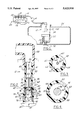
- FIG. 7 is a fragmentary sectional view of a fuel pump manifold having the valve assembly of FIG. 2 shown with the check valve and the vent valve in their respective closed positions;
- FIG. 8 is a side view of the manifold of FIG. 7 encapsulated in a cover of a fuel pump module.
- FIG. 1 illustrates an integrated fuel pump module 10 with a dual valve assembly 12 embodying this invention connected by a fuel line 14 to a fuel rail 16 and associated fuel injectors 18 of an internal combustion engine 20 for an automotive vehicle and also provided with an air intake manifold 22 and an exhaust manifold 24.
- pump module 10 is mounted in a fuel tank 26 and has a fuel level sensor 28 and a fuel pump 30 with an outlet connected to valve assembly 12 and an inlet communicating with the bottom of the tank through a fuel filter 32.
- the pump is driven b an electric motor 34, the speed of which may be varied to control the pressure of fuel delivered by the pump to the engine.
- the fuel system has no fuel return line from the engine to the fuel tank and hence is of the type often referred to as a "no-return" or "returnless" fuel system.
- valve assembly 12 has a housing 40 preferably molded of a synthetic resin.
- Housing 40 is of a generally cylindrical, dual diameter stepped shape having a bore 41 meeting a counterbore 41a at a shoulder 42.
- a fuel supply passage 43 extends axially through the entire length of the housing.
- An inlet 44 of the housing is connected in assembly to the outlet of fuel pump 30.
- the housing also has an outlet 46 communicating with inlet 44 through fuel passage 43 and an outlet connector 48 which in assembly is connected to fuel line 14.
- a normally closed check valve assembly 50 included within valve assembly 12 and which normally opens when the fuel pump is energized and allows fuel to flow through the fuel passage to the outlet.
- Check valve assembly 50 is yieldably biased closed against a movable valve seat 52, and comprises a poppet valve body 54 slidably received with a loose clearance in bore 41.
- Valve body 54 is yieldably biased to its closed position by a compression coil spring 56 retained at its upper end by a star washer 58 press fit into the cylindrical bore 41 of housing 40 upstream of the outlet 46 of fuel passage 43.
- Valve body 54 has a frusto conical surface 60 tapering towards inlet 44 of valve assembly 12.
- Valve seat 52 is tapered to the same degree as surface 60 to provide the mating seating surface.
- the lower end of spring 56 rests against valve body 54 and is radially retained by a shoulder 62 on the valve body.
- valve body 54 presses against valve seat 52 to provide a seal, and when check valve assembly 50 is open (FIG. 6), fuel flows through fuel passage 43 via the clearance between bore 41 and valve body 54 and then through peripheral grooves 63 in star washer 58 which provide continuously open ports 64 to outlet 46.
- valve stem 66 protrudes from valve body 54 axially within housing bore 41 and passes slidably through a central opening 68 in star washer 58 to axially align and guide axial movement of the valve body within housing bore 41.
- valve stem 66 is brass and valve body 54 is a molded flourosilicone resin or other synthetic resin; both highly resistant to deterioration by gasoline, alcohol, diesel fuels and their usual contaminants.
- Valve assembly 12 also includes a normally closed vent valve assembly 70 disposed in fuel passage 43 upstream of check valve assembly 50.
- Valve assembly 70 has a fixed valve seat 72, preferably molded as an annular rib-integral with shoulder 42 of housing 40, a valve body 74, also molded of a synthetic resin, slidably received in housing counterbore 41a and yieldably biased to its closed position by a compression coil spring 76 retained by a washer 78 press fit into counterbore 41a near inlet 44 of housing 40.
- Valve body 74 is preferably a hollow cylindrical cup-like body with an outside diameter providing a close sliding fit within counterbore 41a defining inlet 44.
- valve body 74 The upstream end 80 of valve body 74 is open, and the downstream end 82 is capped off by an end closure wall 83 integrally molded with the valve body and having a flat exterior surface 84 adapted to sealably seat against rib valve seat 72.
- Wall 83 has an annular reinforcing rib 85 which defines a tapered bore 86, centrally located in wall 84. Bore 86 provides the mating surface defining valve seat 52 for sealably engaging surface 60 of check valve body 54.
- Longitudinal grooves 87 are provided on the outer surface 88 of valve body 74 which extend the entire length thereof and define fuel bleed ports 90 between the housing counterbore 41a and valve body 74 which allow fuel to bleed back around the check valve when the vent valve assembly is open (FIG. 5).
- check valve assembly 50 When check valve assembly 50 is open (FIG. 6), fuel passes within the fuel passage 43 from inlet 44 through a fuel delivery port 92 centrally located in washer 78, through tapered bore 86 and around check valve
- Vent valve seat 72 is formed integral with housing shoulder 42 as an annular rib within fuel passage 43. Valve seat 72 abuts surface 84 radially inwardly of grooves 87 to thereby completely close off bleed ports 90 when vent valve assembly 70 is in the closed position with valve body 74 in abutment with valve seat 72, as shown in FIGS. 2 and 6.
- Spring 76 abuts at its upstream end against washer 78 and at its downstream end against the inside face of wall 83 thereby normally biasing valve body 74 against valve seat 72.
- the pre-load force produced by spring 76 and its spring rate are determined and selected such that the vent valve assembly 70 is normally closed and will open at a predetermined pressure differential, which is about equal to the desired minimum engine idle fuel pressure, usually about 25 psig. This is to maintain a minimum idle fuel pressure at the injectors and yet avoid an overly rich fuel to air mixture for the next engine start-up or increased throttle condition and to avoid a momentary overly rich fuel to air mixture when engine fuel demand rapidly goes from full throttle
- FIGS. 7 and 8 illustrate a fuel pump manifold 100 having a housing 102 preferably molded of a synthetic resin.
- Electronic circuitry therein (not shown) varies and controls the speed of electric drive motor 34 and hence the output of the fuel pump 30 shown in FIG. 1.
- the manifold is encased by injection molding around it, a cover or top cap 104 of the fuel pump module, also of a synthetic resin.
- housing 102 has a fuel inlet 106 and a connector 108 which in assembly is connected to the outlet of the fuel pump.
- the manifold also has a fuel outlet 110 communicating with inlet 106 through a fuel passage 112 and an outlet connector 114 which in assembly is connected to the fuel delivery line 14.
- an additional normally closed relief valve assembly 120 is disposed within housing 102 in a passage 121 which communicates with the passage 112 downstream of valve assembly 12 and with the fuel pump module 10 and thence the fuel tank 26 by opening to the exterior of the housing 102.
- the relief valve assembly 120 has a valve body 122 with a hemispherical valve head 124 yieldably biased by a compression spring 126 into sealing engagement with a complementary seat 128 which is preferably spherical and molded in the housing 102.
- the body has a stem 130 slidably received in a bore 132 through a shank 134 of a retainer cap 136 press fit into a counterbore 138 in the housing.
- a stem 130 slidably received in a bore 132 through a shank 134 of a retainer cap 136 press fit into a counterbore 138 in the housing.
- the shank 134 projects into the spring and has an outside diameter which is only slightly smaller than the inside diameter of the spring. The extent to which the valve can be opened is limited by the valve body abutting the free end of the shank.
- the stem 130 of the valve body is brass and its hemispherical head 124 is a molded flourosilicone resin or other synthetic resin highly resistant to attack and deterioration by gasoline, alcohol and diesel fuels and the contaminants normally found therein.
- the relief valve preload force is determined and selected so that relief valve 120 is normally closed and will open at a predetermined pressure which is usually about 10 to 15 psi greater than the maximum normal operating pressure of the fuel system which is usually 40 to 60 psig.
- the relief valve protects the fuel system in the event there is a malfunction which causes the pump to continuously operate at maximum pressure or during periods of so-called "hot soaking" (with the engine running) where the pressure of the fuel increases above the desired maximum operating pressure due to an excessively high temperature of the fuel.
- the engine control module is programmed to cause the fuel pump to operate at maximum pressure so that the vehicle can "limp" home or be operated and driven to a service station for repair of the malfunction.
- the speed of electric motor 34 driving fuel pump 30 and hence the pressure of fuel supplied through valve assembly 12 to the engine is suitably controlled in a conventional manner in response to the load on the engine and other engine operating conditions.
- the fuel pressure supplied to the engine is momentarily greater than desired. Similar conditions occur in a vehicle with a manual transmission, as during each shift there are rapid throttle modulations changing engine conditions from load to idle and idle to load.
- vent valve 70 opens allowing fuel to bypass check valve 50 and flow back through the pump. This occurs until the pressure differential across the dual valve assembly is about 25 psi or the minimum fuel pressure necessary for idle. Also, by bleeding fuel back through the fuel pump, parasitic loss of fuel is avoided.
- Vent valve 70 closes when the pressure differential across the dual valve decreases to less than 25 psi.
- Check valve 50 opens allowing fuel to flow to the engine when the pump outlet pressure exceeds the fuel pressure down stream of the dual valve.
- the fuel system may be subjected to what is termed a "hot soak" condition.
- a hot soak condition When the engine and fuel pump are shut off or operating at idle, engine compartment temperatures may rise due to hot weather conditions or hot engine components, thereby causing thermal expansion of the fuel downstream of check valve 50. Under such conditions, the vent valve 70 will again open as previously described to prevent an engine hot soak over pressure condition.
- the predetermined minimum pressure is preferably about equal to the fuel pressure required at engine idle conditions. This minimum fuel pressure will be maintained downstream of the check valve assembly to prevent fuel delivery delays for the next successive engine start-up or increased throttle condition needed for engine acceleration.
- check valve and/or relief valve bodies may be molded semihemispherical bodies and the valve seat mating surfaces molded to correspond.
- the check valve spring stop may be molded integral with the housing.
- the fuel delivery bore and bleed ports may take on a number of configurations and yet remain within the scope of the invention.
- the moveable valve seat may be the vent valve seat and the fixed valve seat the check valve seat without departing from the scope of the invention.
Abstract
Description
Claims (20)
Priority Applications (4)
| Application Number | Priority Date | Filing Date | Title |
|---|---|---|---|
| US08/347,283 US5623910A (en) | 1994-11-30 | 1994-11-30 | Check and vent valve assembly |
| DE19541086A DE19541086A1 (en) | 1994-11-30 | 1995-11-03 | Valve arrangement for a disposable fuel system |
| FR9513352A FR2727470B1 (en) | 1994-11-30 | 1995-11-10 | VALVE ASSEMBLY FOR NON-RETURN FUEL CIRCUIT |
| JP7301180A JPH08226557A (en) | 1994-11-30 | 1995-11-20 | Check and relief combination valve |
Applications Claiming Priority (1)
| Application Number | Priority Date | Filing Date | Title |
|---|---|---|---|
| US08/347,283 US5623910A (en) | 1994-11-30 | 1994-11-30 | Check and vent valve assembly |
Publications (1)
| Publication Number | Publication Date |
|---|---|
| US5623910A true US5623910A (en) | 1997-04-29 |
Family
ID=23363085
Family Applications (1)
| Application Number | Title | Priority Date | Filing Date |
|---|---|---|---|
| US08/347,283 Expired - Lifetime US5623910A (en) | 1994-11-30 | 1994-11-30 | Check and vent valve assembly |
Country Status (4)
| Country | Link |
|---|---|
| US (1) | US5623910A (en) |
| JP (1) | JPH08226557A (en) |
| DE (1) | DE19541086A1 (en) |
| FR (1) | FR2727470B1 (en) |
Cited By (43)
| Publication number | Priority date | Publication date | Assignee | Title |
|---|---|---|---|---|
| WO1999029392A1 (en) * | 1997-12-06 | 1999-06-17 | Robert Bosch Gmbh | Filter for fluids with a built-in pressure controller |
| US5988213A (en) * | 1997-01-31 | 1999-11-23 | Mitsubishi Denki Kabushiki Kaisha | Vehicular fuel supplying apparatus |
| US6067963A (en) * | 1995-10-09 | 2000-05-30 | Nippondenso Co., Ltd. | Fuel supply system with fuel evaporation prevention |
| US6209527B1 (en) * | 1996-08-29 | 2001-04-03 | Robert Bosch Gmbh | Pressure regulating valve |
| US6283142B1 (en) | 2000-02-04 | 2001-09-04 | Robert Bosch Corporation | Dual fuel delivery module system for bifurcated automotive fuel tanks |
| FR2806974A1 (en) * | 2000-03-29 | 2001-10-05 | Eurocopter Deutschland | VALVE DEVICE FOR A FUEL SUPPLY LINE OF AN INTERNAL COMBUSTION ENGINE FROM A TANK |
| US6352067B1 (en) * | 2000-07-26 | 2002-03-05 | Visteon Global Technologies, Inc. | Returnless fuel system pressure valve with two-way parasitic flow orifice |
| US6371153B1 (en) | 2001-03-16 | 2002-04-16 | Robert Bosch Corporation | Dual fuel delivery module system for multi-chambered or multiple automotive fuel tanks |
| US6371088B1 (en) | 2000-06-21 | 2002-04-16 | Robert Bosch Corporation | Self-relieving fuel filter assembly |
| US6401693B1 (en) * | 2000-09-01 | 2002-06-11 | Schrader-Bridgeport International, Inc. | Pressure spike attenuator for automotive fuel injection system |
| US6422255B1 (en) | 2000-08-03 | 2002-07-23 | Bombardier Motor Corporation Of America | Multi-function valve having a movable seat and needle |
| US20030034073A1 (en) * | 2001-08-16 | 2003-02-20 | Roth Robert A. | Check valve for fuel pump |
| US20030070876A1 (en) * | 1998-04-06 | 2003-04-17 | Tamotsu Takahara | Oil drain plug of engine |
| US20030084941A1 (en) * | 2001-11-07 | 2003-05-08 | Fischer John Gardner | Check valve for fuel pump |
| US20040069353A1 (en) * | 2002-10-09 | 2004-04-15 | Pickelman Dale M. | Check valve for fuel pump |
| US6722346B2 (en) * | 2000-05-13 | 2004-04-20 | Siemens Aktiengesellschaft | Connection |
| US6758235B2 (en) | 2002-09-30 | 2004-07-06 | Alfmeier Prazision Ag Baugruppen Und Systemlosungen | Vapor control valve with a metallic sealing element |
| US20040173265A1 (en) * | 2003-03-04 | 2004-09-09 | Roth Robert A. | Check valve for fuel pump |
| GB2400641A (en) * | 2003-04-15 | 2004-10-20 | Visteon Global Tech Inc | Fuel pressure relief valve |
| US20050028869A1 (en) * | 2003-08-04 | 2005-02-10 | Roth Robert A. | Combination valve for fuel system |
| US20050061372A1 (en) * | 2003-09-23 | 2005-03-24 | Mcgrath Dennis P. | Pressure regulator assembly |
| US20050081830A1 (en) * | 2003-10-16 | 2005-04-21 | Visteon Global Technologies, Inc. | Pressure regulating valve for automotive fuel system |
| US20050081826A1 (en) * | 2003-10-16 | 2005-04-21 | Visteon Global Technologies, Inc. | Mechanical returnless fuel system |
| WO2005075809A1 (en) * | 2004-01-30 | 2005-08-18 | Siemens Aktiengesellschaft | Coupling valve structure for fuel supply module |
| US20050284539A1 (en) * | 2004-06-28 | 2005-12-29 | Ralf Leonhardt | Fill limit vent valve assembly |
| US20060048752A1 (en) * | 2004-09-03 | 2006-03-09 | Visteon Global Technologies, Inc. | Low evaporative emission fuel system depressurization via solenoid valve |
| US20060236983A1 (en) * | 2005-04-26 | 2006-10-26 | Yoshiaki Douyama | Bypass pressure regulator |
| US20060243329A1 (en) * | 2005-04-29 | 2006-11-02 | Ti Group Automotive Systems, L.L.C. | Check valve apparatus for fuel delivery systems |
| US7228849B1 (en) * | 2006-09-29 | 2007-06-12 | Delphi Technologies, Inc. | Conical concave cap pressure relief valve |
| US20080149069A1 (en) * | 2004-06-04 | 2008-06-26 | Robert Bosch Gmbh | Fuel Injection System |
| US20090084354A1 (en) * | 2007-09-27 | 2009-04-02 | Caterpillar Inc. | High-pressure pump or injector plug or guide with decoupled sealing land |
| US20090126805A1 (en) * | 2005-06-16 | 2009-05-21 | Vladimir Olshanetsky | Double Check Valve for a Fuel System |
| US20100258092A1 (en) * | 2007-11-05 | 2010-10-14 | Volkhard Ammon | Fuel overflow valve for a fuel injection system, and fuel injection system having a fuel overflow valve |
| US20100263755A1 (en) * | 2009-04-20 | 2010-10-21 | Rolls-Royce Plc | Fuel distributor valve |
| US20110223040A1 (en) * | 2008-11-26 | 2011-09-15 | Uwe Lingener | High-pressure pump arrangement |
| US20110297260A1 (en) * | 2010-06-03 | 2011-12-08 | Robert Bosch Gmbh | Fuel system including dual fuel delivery modules for bifurcated fuel tanks |
| US20120073546A1 (en) * | 2010-09-24 | 2012-03-29 | Denso Corporation | Cleaning a pressure control function valve |
| US20130056098A1 (en) * | 2011-09-01 | 2013-03-07 | Continental Automotive Systems Us, Inc. | Compact fuel pressure regulator |
| US20130312706A1 (en) * | 2012-05-23 | 2013-11-28 | Christopher J. Salvador | Fuel system having flow-disruption reducer |
| US9027594B2 (en) | 2012-03-30 | 2015-05-12 | Ti Group Automotive Systems, L.L.C. | Fuel system valve assembly |
| US20190003432A1 (en) * | 2016-01-12 | 2019-01-03 | Continental Automotive Gmbh | Fuel Injection System |
| US10527017B2 (en) | 2015-06-10 | 2020-01-07 | Denso Corporation | High-pressure pump |
| US11300080B2 (en) * | 2019-05-17 | 2022-04-12 | Dayco Ip Holdings, Llc | Fuel tank protector valve and engine systems having same |
Families Citing this family (9)
| Publication number | Priority date | Publication date | Assignee | Title |
|---|---|---|---|---|
| DE19651188C2 (en) * | 1996-12-10 | 2000-04-13 | Mannesmann Vdo Ag | Fuel supply unit |
| BR9904868A (en) * | 1998-02-27 | 2000-09-26 | Stanadyne Automotive Corp | Fuel supply pump and process of operating a fuel injection system |
| JP3742852B2 (en) * | 1999-01-13 | 2006-02-08 | ダイキン工業株式会社 | Air conditioner |
| DE10153037A1 (en) * | 2001-10-26 | 2003-05-08 | Bayerische Motoren Werke Ag | Arrangement for supplying internal combustion engine injection valves with fuel, has fuel pump, via which fuel mass flow can be varied, that acts as control element for regulator |
| FR2925614B1 (en) * | 2007-12-21 | 2009-12-25 | Coutier Moulage Gen Ind | PRESSURE REGULATION AND MAINTENANCE DEVICE FOR MOUNTING ON A FUEL RETURN CIRCUIT OF A MOTOR VEHICLE |
| DE102008000739A1 (en) * | 2008-03-18 | 2009-09-24 | Robert Bosch Gmbh | Pressure holding valve |
| DE102017213518A1 (en) | 2017-08-03 | 2019-02-07 | Bayerische Motoren Werke Aktiengesellschaft | Tank for a motor vehicle |
| DE102017213517A1 (en) | 2017-08-03 | 2019-02-07 | Bayerische Motoren Werke Aktiengesellschaft | Fuel tank for a motor vehicle |
| JP6624264B2 (en) * | 2018-10-11 | 2019-12-25 | 株式会社デンソー | High pressure pump |
Citations (8)
| Publication number | Priority date | Publication date | Assignee | Title |
|---|---|---|---|---|
| US5044344A (en) * | 1989-10-16 | 1991-09-03 | Walbro Corporation | Pressure-responsive fuel delivery system |
| US5148792A (en) * | 1992-01-03 | 1992-09-22 | Walbro Corporation | Pressure-responsive fuel delivery system |
| US5195494A (en) * | 1992-02-27 | 1993-03-23 | Walbro Corporation | Fuel delivery system with outlet pressure regulation |
| US5289810A (en) * | 1992-07-29 | 1994-03-01 | Robert Bosch Gmbh | Arrangement for supplying fuel from supply tank to internal combustion engine of motor vehicle |
| US5295469A (en) * | 1990-07-09 | 1994-03-22 | Nippondenso Co., Ltd. | Safety valve for fuel injection apparatus |
| US5339785A (en) * | 1992-06-29 | 1994-08-23 | Ford Motor Company | Automotive fuel supply apparatus and control valve |
| US5361742A (en) * | 1993-02-08 | 1994-11-08 | Walbro Corporation | Fuel pump manifold |
| US5365906A (en) * | 1993-12-20 | 1994-11-22 | Chrysler Corporation | Fluid flow check valve for fuel system |
Family Cites Families (1)
| Publication number | Priority date | Publication date | Assignee | Title |
|---|---|---|---|---|
| DE3833580A1 (en) * | 1988-10-03 | 1990-04-05 | Vdo Schindling | Connection piece for a pump |
-
1994
- 1994-11-30 US US08/347,283 patent/US5623910A/en not_active Expired - Lifetime
-
1995
- 1995-11-03 DE DE19541086A patent/DE19541086A1/en not_active Withdrawn
- 1995-11-10 FR FR9513352A patent/FR2727470B1/en not_active Expired - Fee Related
- 1995-11-20 JP JP7301180A patent/JPH08226557A/en not_active Withdrawn
Patent Citations (8)
| Publication number | Priority date | Publication date | Assignee | Title |
|---|---|---|---|---|
| US5044344A (en) * | 1989-10-16 | 1991-09-03 | Walbro Corporation | Pressure-responsive fuel delivery system |
| US5295469A (en) * | 1990-07-09 | 1994-03-22 | Nippondenso Co., Ltd. | Safety valve for fuel injection apparatus |
| US5148792A (en) * | 1992-01-03 | 1992-09-22 | Walbro Corporation | Pressure-responsive fuel delivery system |
| US5195494A (en) * | 1992-02-27 | 1993-03-23 | Walbro Corporation | Fuel delivery system with outlet pressure regulation |
| US5339785A (en) * | 1992-06-29 | 1994-08-23 | Ford Motor Company | Automotive fuel supply apparatus and control valve |
| US5289810A (en) * | 1992-07-29 | 1994-03-01 | Robert Bosch Gmbh | Arrangement for supplying fuel from supply tank to internal combustion engine of motor vehicle |
| US5361742A (en) * | 1993-02-08 | 1994-11-08 | Walbro Corporation | Fuel pump manifold |
| US5365906A (en) * | 1993-12-20 | 1994-11-22 | Chrysler Corporation | Fluid flow check valve for fuel system |
Cited By (73)
| Publication number | Priority date | Publication date | Assignee | Title |
|---|---|---|---|---|
| US6067963A (en) * | 1995-10-09 | 2000-05-30 | Nippondenso Co., Ltd. | Fuel supply system with fuel evaporation prevention |
| US6209527B1 (en) * | 1996-08-29 | 2001-04-03 | Robert Bosch Gmbh | Pressure regulating valve |
| US5988213A (en) * | 1997-01-31 | 1999-11-23 | Mitsubishi Denki Kabushiki Kaisha | Vehicular fuel supplying apparatus |
| WO1999029392A1 (en) * | 1997-12-06 | 1999-06-17 | Robert Bosch Gmbh | Filter for fluids with a built-in pressure controller |
| US20030070876A1 (en) * | 1998-04-06 | 2003-04-17 | Tamotsu Takahara | Oil drain plug of engine |
| US6902038B2 (en) * | 1998-04-06 | 2005-06-07 | Tamotsu Takahara | Oil drain plug of engine |
| US6283142B1 (en) | 2000-02-04 | 2001-09-04 | Robert Bosch Corporation | Dual fuel delivery module system for bifurcated automotive fuel tanks |
| FR2806974A1 (en) * | 2000-03-29 | 2001-10-05 | Eurocopter Deutschland | VALVE DEVICE FOR A FUEL SUPPLY LINE OF AN INTERNAL COMBUSTION ENGINE FROM A TANK |
| US6668802B2 (en) | 2000-03-29 | 2003-12-30 | Eurocopter Deutschland Gmbh | Valve arrangement in a feed line to deliver fuel from a tank to an internal combustion engine |
| US6722346B2 (en) * | 2000-05-13 | 2004-04-20 | Siemens Aktiengesellschaft | Connection |
| US6371088B1 (en) | 2000-06-21 | 2002-04-16 | Robert Bosch Corporation | Self-relieving fuel filter assembly |
| US6352067B1 (en) * | 2000-07-26 | 2002-03-05 | Visteon Global Technologies, Inc. | Returnless fuel system pressure valve with two-way parasitic flow orifice |
| US6422255B1 (en) | 2000-08-03 | 2002-07-23 | Bombardier Motor Corporation Of America | Multi-function valve having a movable seat and needle |
| US6401693B1 (en) * | 2000-09-01 | 2002-06-11 | Schrader-Bridgeport International, Inc. | Pressure spike attenuator for automotive fuel injection system |
| US6371153B1 (en) | 2001-03-16 | 2002-04-16 | Robert Bosch Corporation | Dual fuel delivery module system for multi-chambered or multiple automotive fuel tanks |
| US20030034073A1 (en) * | 2001-08-16 | 2003-02-20 | Roth Robert A. | Check valve for fuel pump |
| US20030084941A1 (en) * | 2001-11-07 | 2003-05-08 | Fischer John Gardner | Check valve for fuel pump |
| US6877525B2 (en) | 2001-11-07 | 2005-04-12 | Delphi Technologies, Inc. | Check valve for fuel pump |
| US6758235B2 (en) | 2002-09-30 | 2004-07-06 | Alfmeier Prazision Ag Baugruppen Und Systemlosungen | Vapor control valve with a metallic sealing element |
| US20040069353A1 (en) * | 2002-10-09 | 2004-04-15 | Pickelman Dale M. | Check valve for fuel pump |
| US6971405B2 (en) | 2002-10-09 | 2005-12-06 | Delphi Technologies, Inc. | Check valve for fuel pump |
| US20040173265A1 (en) * | 2003-03-04 | 2004-09-09 | Roth Robert A. | Check valve for fuel pump |
| US6994108B2 (en) | 2003-03-04 | 2006-02-07 | Delphi Technologies, Inc. | Check valve for fuel pump |
| US20040206338A1 (en) * | 2003-04-15 | 2004-10-21 | Visteon Global Technologies, Inc. | Fuel pressure relief valve |
| GB2400641A (en) * | 2003-04-15 | 2004-10-20 | Visteon Global Tech Inc | Fuel pressure relief valve |
| GB2400641B (en) * | 2003-04-15 | 2005-03-23 | Visteon Global Tech Inc | Fuel pressure relief valve |
| US6988488B2 (en) | 2003-04-15 | 2006-01-24 | Visteon Global Technologies, Inc. | Fuel pressure relief valve |
| US7086388B2 (en) * | 2003-08-04 | 2006-08-08 | Delphi Technologies, Inc. | Combination valve for fuel system |
| US20050028869A1 (en) * | 2003-08-04 | 2005-02-10 | Roth Robert A. | Combination valve for fuel system |
| US20050061372A1 (en) * | 2003-09-23 | 2005-03-24 | Mcgrath Dennis P. | Pressure regulator assembly |
| WO2005031201A1 (en) * | 2003-09-23 | 2005-04-07 | Delphi Technologies, Inc. | Pressure regulator assembly |
| US20050081830A1 (en) * | 2003-10-16 | 2005-04-21 | Visteon Global Technologies, Inc. | Pressure regulating valve for automotive fuel system |
| US20050081826A1 (en) * | 2003-10-16 | 2005-04-21 | Visteon Global Technologies, Inc. | Mechanical returnless fuel system |
| US6953026B2 (en) | 2003-10-16 | 2005-10-11 | Visteon Global Technologies, Inc. | Pressure regulating valve for automotive fuel system |
| US7302938B2 (en) | 2003-10-16 | 2007-12-04 | Ford Motor Company | Mechanical returnless fuel system |
| CN1914416B (en) * | 2004-01-30 | 2013-04-10 | 大陆汽车有限责任公司 | Coupling valve structure for fuel supply module |
| WO2005075809A1 (en) * | 2004-01-30 | 2005-08-18 | Siemens Aktiengesellschaft | Coupling valve structure for fuel supply module |
| KR101194484B1 (en) * | 2004-01-30 | 2012-10-24 | 콘티넨탈 오토모티브 게엠베하 | Coupling valve structure for fuel supply module |
| US7574994B2 (en) * | 2004-06-04 | 2009-08-18 | Robert Bosch Gmbh | Fuel injection system |
| US20080149069A1 (en) * | 2004-06-04 | 2008-06-26 | Robert Bosch Gmbh | Fuel Injection System |
| US20050284539A1 (en) * | 2004-06-28 | 2005-12-29 | Ralf Leonhardt | Fill limit vent valve assembly |
| US7147017B2 (en) | 2004-06-28 | 2006-12-12 | Alfmeier Corporation | Fill limit vent valve assembly |
| US20060048752A1 (en) * | 2004-09-03 | 2006-03-09 | Visteon Global Technologies, Inc. | Low evaporative emission fuel system depressurization via solenoid valve |
| US7066152B2 (en) | 2004-09-03 | 2006-06-27 | Ford Motor Company | Low evaporative emission fuel system depressurization via solenoid valve |
| US7210460B2 (en) * | 2005-04-26 | 2007-05-01 | Walbro Engine Management, L.L.C. | Bypass pressure regulator |
| US20060236983A1 (en) * | 2005-04-26 | 2006-10-26 | Yoshiaki Douyama | Bypass pressure regulator |
| US20060243329A1 (en) * | 2005-04-29 | 2006-11-02 | Ti Group Automotive Systems, L.L.C. | Check valve apparatus for fuel delivery systems |
| US7726335B2 (en) | 2005-04-29 | 2010-06-01 | Ti Group Automotive Systems, L.L.C. | Check valve apparatus for fuel delivery systems |
| US8091583B2 (en) | 2005-06-16 | 2012-01-10 | Raval A.C.S. Ltd. | Double check valve for a fuel system |
| US20090126805A1 (en) * | 2005-06-16 | 2009-05-21 | Vladimir Olshanetsky | Double Check Valve for a Fuel System |
| US7228849B1 (en) * | 2006-09-29 | 2007-06-12 | Delphi Technologies, Inc. | Conical concave cap pressure relief valve |
| US7628140B2 (en) * | 2007-09-27 | 2009-12-08 | Caterpillar Inc. | High-pressure pump or injector plug or guide with decoupled sealing land |
| US20090084354A1 (en) * | 2007-09-27 | 2009-04-02 | Caterpillar Inc. | High-pressure pump or injector plug or guide with decoupled sealing land |
| US20100258092A1 (en) * | 2007-11-05 | 2010-10-14 | Volkhard Ammon | Fuel overflow valve for a fuel injection system, and fuel injection system having a fuel overflow valve |
| US8973557B2 (en) * | 2007-11-05 | 2015-03-10 | Robert Bosch Gmbh | Fuel overflow valve for a fuel injection system, and fuel injection system having a fuel overflow valve |
| CN101849096B (en) * | 2007-11-05 | 2013-06-19 | 罗伯特·博世有限公司 | Fuel overflow valve for a fuel injection system, and fuel injection system having a fuel overflow valve |
| US20110223040A1 (en) * | 2008-11-26 | 2011-09-15 | Uwe Lingener | High-pressure pump arrangement |
| US9103307B2 (en) | 2008-11-26 | 2015-08-11 | Continental Automotive Gmbh | High-pressure pump arrangement |
| US20100263755A1 (en) * | 2009-04-20 | 2010-10-21 | Rolls-Royce Plc | Fuel distributor valve |
| US20110297260A1 (en) * | 2010-06-03 | 2011-12-08 | Robert Bosch Gmbh | Fuel system including dual fuel delivery modules for bifurcated fuel tanks |
| US8720485B2 (en) * | 2010-06-03 | 2014-05-13 | Robert Bosch Gmbh | Fuel system including dual fuel delivery modules for bifurcated fuel tanks |
| US20120073546A1 (en) * | 2010-09-24 | 2012-03-29 | Denso Corporation | Cleaning a pressure control function valve |
| US8622047B2 (en) * | 2010-09-24 | 2014-01-07 | Denso Corporation | Cleaning a pressure control function valve |
| US20130056098A1 (en) * | 2011-09-01 | 2013-03-07 | Continental Automotive Systems Us, Inc. | Compact fuel pressure regulator |
| US9587603B2 (en) * | 2011-09-01 | 2017-03-07 | Continental Automotive Systems, Inc. | Compact fuel pressure regulator |
| US9027594B2 (en) | 2012-03-30 | 2015-05-12 | Ti Group Automotive Systems, L.L.C. | Fuel system valve assembly |
| EP2644954B1 (en) | 2012-03-30 | 2017-03-08 | TI Group Automotive Systems, L.L.C. | Fuel system valve assembly |
| EP2644954B2 (en) † | 2012-03-30 | 2020-12-23 | TI Group Automotive Systems, L.L.C. | Fuel system valve assembly |
| US20130312706A1 (en) * | 2012-05-23 | 2013-11-28 | Christopher J. Salvador | Fuel system having flow-disruption reducer |
| US10527017B2 (en) | 2015-06-10 | 2020-01-07 | Denso Corporation | High-pressure pump |
| US10907599B2 (en) | 2015-06-10 | 2021-02-02 | Denso Corporation | High-pressure pump |
| US20190003432A1 (en) * | 2016-01-12 | 2019-01-03 | Continental Automotive Gmbh | Fuel Injection System |
| US11300080B2 (en) * | 2019-05-17 | 2022-04-12 | Dayco Ip Holdings, Llc | Fuel tank protector valve and engine systems having same |
Also Published As
| Publication number | Publication date |
|---|---|
| DE19541086A1 (en) | 1996-06-13 |
| FR2727470A1 (en) | 1996-05-31 |
| JPH08226557A (en) | 1996-09-03 |
| FR2727470B1 (en) | 1998-04-30 |
Similar Documents
| Publication | Publication Date | Title |
|---|---|---|
| US5623910A (en) | Check and vent valve assembly | |
| US5361742A (en) | Fuel pump manifold | |
| EP0759122B1 (en) | Non-return fuel system with fuel pressure vacuum response | |
| US7726335B2 (en) | Check valve apparatus for fuel delivery systems | |
| US5579739A (en) | Returnless fuel system with demand fuel pressure regulator | |
| US8091583B2 (en) | Double check valve for a fuel system | |
| US5482021A (en) | Air/fuel handling system for fuel injection engine | |
| EP2055925B1 (en) | Fuel injection metering valves | |
| CA1262666A (en) | Fuel line purging device | |
| US6422212B1 (en) | On-off valve in a fuel injection system for internal combustion engines | |
| US6357415B1 (en) | Fuel shut-off device for internal combustion engine | |
| JP2747428B2 (en) | Demand fuel pressure regulator | |
| EP0198381B1 (en) | Fuel pressure regulator | |
| US20030111050A1 (en) | Fuel-injection system comprising pressure regulation in the return line | |
| US6039030A (en) | Fuel system containing a shape memory alloy | |
| US5605133A (en) | Fuel rail pressure control | |
| US4774923A (en) | Pressure regulating valve | |
| AU2005200794B2 (en) | Gas feeding system for an internal combustion engine, having a pressure reducing valve connected to the intake manifold | |
| US4393825A (en) | System for controlling fuel flow within an internal combustion engine | |
| US5699664A (en) | Shut-off valve unit for a circuit for injecting air in the exhaust system of an internal combustion engine | |
| US5619972A (en) | Demand pressure regulator | |
| JP2004517254A (en) | Injection valve | |
| JP2003513196A (en) | Injector with hydraulically preloaded pressure transducer for fuel injection systems of internal combustion engines | |
| US6820827B1 (en) | Injector for a fuel injection system for internal combustion engines, having a nozzle needle protruding into the valve control chamber | |
| US6971592B2 (en) | Fuel injection device for an internal combustion engine |
Legal Events
| Date | Code | Title | Description |
|---|---|---|---|
| AS | Assignment |
Owner name: WALBRO CORPORATION, MICHIGAN Free format text: ASSIGNMENT OF ASSIGNORS INTEREST;ASSIGNOR:RIGGLE, RUSSELL K.;REEL/FRAME:007261/0290 Effective date: 19941118 |
|
| STCF | Information on status: patent grant |
Free format text: PATENTED CASE |
|
| AS | Assignment |
Owner name: NATIONSBANK, N.A., MARYLAND Free format text: SECURITY INTEREST;ASSIGNOR:WALBRO CORPORATION;REEL/FRAME:009297/0790 Effective date: 19980529 |
|
| FPAY | Fee payment |
Year of fee payment: 4 |
|
| AS | Assignment |
Owner name: TI GROUP AUTOMOTIVE SYSTEMS, L.L.C. OF DELAWARE, M Free format text: ASSIGNMENT OF ASSIGNORS INTEREST;ASSIGNOR:WALBRO CORPORATION OF DELAWARE;REEL/FRAME:014845/0830 Effective date: 20031105 |
|
| FPAY | Fee payment |
Year of fee payment: 8 |
|
| AS | Assignment |
Owner name: WALBRO CORPORATION, MICHIGAN Free format text: RELEASE OF PATENT ASSIGNMENT;ASSIGNOR:BANK OF AMERICA, N.A. (F/K/A NATIONSBANK, N.A.);REEL/FRAME:018837/0814 Effective date: 20070118 |
|
| AS | Assignment |
Owner name: JPMORGAN CHASE BANK, N.A., NEW YORK Free format text: SECURITY AGREEMENT;ASSIGNORS:HANIL USA, L.L.C.;TI AUTOMOTIVE, L.L.C.;TI GROUP AUTOMOTIVE SYSTEMS, L.L.C.;REEL/FRAME:019733/0933 Effective date: 20070629 Owner name: JPMORGAN CHASE BANK, N.A.,NEW YORK Free format text: SECURITY AGREEMENT;ASSIGNORS:HANIL USA, L.L.C.;TI AUTOMOTIVE, L.L.C.;TI GROUP AUTOMOTIVE SYSTEMS, L.L.C.;REEL/FRAME:019733/0933 Effective date: 20070629 |
|
| FPAY | Fee payment |
Year of fee payment: 12 |
|
| AS | Assignment |
Owner name: WILMINGTON TRUST (LONDON) LIMITED,UNITED KINGDOM Free format text: ASSIGNMENT OF SECURITY INTEREST;ASSIGNOR:JP MORGAN CHASE BANK, N.A.;REEL/FRAME:024055/0633 Effective date: 20100208 Owner name: WILMINGTON TRUST (LONDON) LIMITED, UNITED KINGDOM Free format text: ASSIGNMENT OF SECURITY INTEREST;ASSIGNOR:JP MORGAN CHASE BANK, N.A.;REEL/FRAME:024055/0633 Effective date: 20100208 |
|
| AS | Assignment |
Owner name: CITIBANK N.A., DELAWARE Free format text: TERM PATENT SECURITY AGREEMENT;ASSIGNOR:TI GROUP AUTOMOTIVE SYSTEMS, L.L.C.;REEL/FRAME:024896/0057 Effective date: 20100825 Owner name: CITIBANK N.A., DELAWARE Free format text: ABL PATENT SECURITY AGREEMENT;ASSIGNOR:TI GROUP AUTOMOTIVE SYSTEMS, L.L.C.;REEL/FRAME:024895/0956 Effective date: 20100825 Owner name: TI AUTOMOTIVE, L.L.C., MICHIGAN Free format text: RELEASE AND TERMINATION OF PATENT SECURITY INTEREST;ASSIGNOR:WILMINGTON TRUST (LONDON) LIMITED (AS SUCCESSOR IN INTEREST TO JP MORGAN CHASE BANK, N.A.);REEL/FRAME:024891/0671 Effective date: 20100825 Owner name: TI GROUP AUTOMOTIVE SYSTEMS, L.L.C., MICHIGAN Free format text: RELEASE AND TERMINATION OF PATENT SECURITY INTEREST;ASSIGNOR:WILMINGTON TRUST (LONDON) LIMITED (AS SUCCESSOR IN INTEREST TO JP MORGAN CHASE BANK, N.A.);REEL/FRAME:024891/0671 Effective date: 20100825 Owner name: HANIL USA, L.L.C., MICHIGAN Free format text: RELEASE AND TERMINATION OF PATENT SECURITY INTEREST;ASSIGNOR:WILMINGTON TRUST (LONDON) LIMITED (AS SUCCESSOR IN INTEREST TO JP MORGAN CHASE BANK, N.A.);REEL/FRAME:024891/0671 Effective date: 20100825 |
|
| AS | Assignment |
Owner name: JPMORGAN CHASE BANK, N.A., NEW YORK Free format text: SECURITY AGREEMENT;ASSIGNORS:TI GROUP AUTOMOTIVE SYSTEMS, L.L.C.;TI AUTOMOTIVE LIMITED;TI AUTOMOTIVE CANADA, INC.;AND OTHERS;REEL/FRAME:027864/0968 Effective date: 20120314 Owner name: TI GROUP AUTOMOTIVE SYSTEMS, L.L.C., MICHIGAN Free format text: RELEASE BY SECURED PARTY;ASSIGNOR:CITIBANK, N.A.;REEL/FRAME:027865/0016 Effective date: 20120314 |
|
| AS | Assignment |
Owner name: TI GROUP AUTOMOTIVE SYSTEMS, L.L.C., MICHIGAN Free format text: TERMINATION AND RELEASE;ASSIGNOR:JPMORGAN CHASE BANK, N.A., AS ADMINISTRATIVE AGENT;REEL/FRAME:036013/0775 Effective date: 20150630 Owner name: TI GROUP AUTOMOTIVE SYSTEMS S DE R.L. DE C.V., MEX Free format text: TERMINATION AND RELEASE;ASSIGNOR:JPMORGAN CHASE BANK, N.A., AS ADMINISTRATIVE AGENT;REEL/FRAME:036013/0775 Effective date: 20150630 Owner name: TI AUTOMOTIVE, L.L.C., MICHIGAN Free format text: TERMINATION AND RELEASE;ASSIGNOR:JPMORGAN CHASE BANK, N.A., AS ADMINISTRATIVE AGENT;REEL/FRAME:036013/0775 Effective date: 20150630 Owner name: TI AUTOMOTIVE LIMITED, UNITED KINGDOM Free format text: TERMINATION AND RELEASE;ASSIGNOR:JPMORGAN CHASE BANK, N.A., AS ADMINISTRATIVE AGENT;REEL/FRAME:036013/0775 Effective date: 20150630 Owner name: HANIL USA L.L.C., ALABAMA Free format text: TERMINATION AND RELEASE;ASSIGNOR:JPMORGAN CHASE BANK, N.A., AS ADMINISTRATIVE AGENT;REEL/FRAME:036013/0775 Effective date: 20150630 Owner name: TI AUTOMOTIVE CANADA, INC., CANADA Free format text: TERMINATION AND RELEASE;ASSIGNOR:JPMORGAN CHASE BANK, N.A., AS ADMINISTRATIVE AGENT;REEL/FRAME:036013/0775 Effective date: 20150630 Owner name: JPMORGAN CHASE BANK, N.A., AS THE COLLATERAL AGENT Free format text: SECURITY AGREEMENT;ASSIGNORS:TI GROUP AUTOMOTIVE SYSTEMS, L.L.C.;HANIL USA, L.L.C.;TI AUTOMOTIVE, L.L.C.;REEL/FRAME:036013/0666 Effective date: 20150630 |