US5629601A - Compound battery charging system - Google Patents
Compound battery charging system Download PDFInfo
- Publication number
- US5629601A US5629601A US08/228,874 US22887494A US5629601A US 5629601 A US5629601 A US 5629601A US 22887494 A US22887494 A US 22887494A US 5629601 A US5629601 A US 5629601A
- Authority
- US
- United States
- Prior art keywords
- batteries
- individual
- voltage
- charging current
- battery
- Prior art date
- Legal status (The legal status is an assumption and is not a legal conclusion. Google has not performed a legal analysis and makes no representation as to the accuracy of the status listed.)
- Expired - Lifetime
Links
Images


Classifications
-
- H—ELECTRICITY
- H01—ELECTRIC ELEMENTS
- H01M—PROCESSES OR MEANS, e.g. BATTERIES, FOR THE DIRECT CONVERSION OF CHEMICAL ENERGY INTO ELECTRICAL ENERGY
- H01M10/00—Secondary cells; Manufacture thereof
- H01M10/42—Methods or arrangements for servicing or maintenance of secondary cells or secondary half-cells
- H01M10/44—Methods for charging or discharging
- H01M10/441—Methods for charging or discharging for several batteries or cells simultaneously or sequentially
-
- H—ELECTRICITY
- H02—GENERATION; CONVERSION OR DISTRIBUTION OF ELECTRIC POWER
- H02J—CIRCUIT ARRANGEMENTS OR SYSTEMS FOR SUPPLYING OR DISTRIBUTING ELECTRIC POWER; SYSTEMS FOR STORING ELECTRIC ENERGY
- H02J7/00—Circuit arrangements for charging or depolarising batteries or for supplying loads from batteries
- H02J7/0013—Circuit arrangements for charging or depolarising batteries or for supplying loads from batteries acting upon several batteries simultaneously or sequentially
- H02J7/0014—Circuits for equalisation of charge between batteries
- H02J7/0018—Circuits for equalisation of charge between batteries using separate charge circuits
-
- Y—GENERAL TAGGING OF NEW TECHNOLOGICAL DEVELOPMENTS; GENERAL TAGGING OF CROSS-SECTIONAL TECHNOLOGIES SPANNING OVER SEVERAL SECTIONS OF THE IPC; TECHNICAL SUBJECTS COVERED BY FORMER USPC CROSS-REFERENCE ART COLLECTIONS [XRACs] AND DIGESTS
- Y02—TECHNOLOGIES OR APPLICATIONS FOR MITIGATION OR ADAPTATION AGAINST CLIMATE CHANGE
- Y02E—REDUCTION OF GREENHOUSE GAS [GHG] EMISSIONS, RELATED TO ENERGY GENERATION, TRANSMISSION OR DISTRIBUTION
- Y02E60/00—Enabling technologies; Technologies with a potential or indirect contribution to GHG emissions mitigation
- Y02E60/10—Energy storage using batteries
Definitions
- An individual lead acid cell may be flat plate, rolled plate, thin or thick, jar or tank formed, starved, gelled or flooded, sealed or unsealed and may have a variety of alloying agents, electrolyte additives and construction variants, i.e., separators, expanders, float energy or power density, cyclic or float life, deep or shallow service, economy or durability and so on.
- the basic system still requires the passage of a net charging current in the reverse direction from discharge to recharge the cell. This requires both an excess voltage (over the equilibrium open circuit voltage) to achieve significant cell current, especially at high state-of-charge, and excess charge (current times time) to compensate for the less than 100% charge storage efficiency of the cell.
- Many parameters of cell construction including plate alloying additives, active material porosity, electrolytic composition, specific gravity, and volume mobility, affect overvoltage requirements, voltage, charge efficiency, and the effect of charge rate (at a given state-of-charge) on cell life and recoverable capacity.
- the “C” rating is defined as the current rating in amps times the number of hours required to discharge a battery. The number of required hours or rating purposes varies with battery type and manufacturer.
- a 1C charge rate into a battery that is at 10% of its full state-of-charge is harmless for virtually any cell construction.
- the same charge rate into a battery having a 90% state-of-charge necessitates substantial overvoltage, reduced charge storage efficiency, generation of significant cell heating, possibly local gassing and, in many cell structures, significant non-uniformities over the plate surfaces. These non-uniformities can cause substantial local morphological variations especially in the positive plate oxide of a lead acid battery, and can cause stratification effects in tall vertical plates (above about 10 inches).
- Reverse current pulses are categorized as long, short, and very short in duration. They tend to enhance charge acceptance, especially at high states-of-charge, by lowering the "barrier" height (the amount of excess voltage needed for charge acceptance) and increasing the efficiency of the net recharge energy by reducing cell heating from moderate rate, late stage, charging conditions.
- the reverse current pulses have been used as an aid in "quick charging" lead acid batteries for decades. However, the use of reverse current pulses, both long and short, fall short of overcoming the limitations in battery charging discussed before.
- Long (in duration) reverse current pulses between about 1 and 15 seconds for lead acid cells, can also be incorporated in the charging system, as generally described before.
- the long reverse pulses are long in duration compared to the initial step function response time of virtually all lead acid cells under most state-of-charge conditions.
- the long reverse pulses at moderate current, generally below 1C and typically below C/10 cause re-equilibrium within the cell (which could be provided by a prolonged zero current "rest” state at significantly higher efficiency) and reverses reactive gradients within the electrolyte.
- the efficient dissolution of dendrites plus the reversal of anomalies over physically large ranges (many inches) helps maintain cell uniformity and tends to reduce cell aging from a "worst case" rate to a "typical” rate.
- long reverse pulses on a long standby basis appears to reverse some cell inhomogeneities, such as sulfation "patches" caused by prolonged storage. Still another possible advantage of these long reverse pulses is the partial restoration of compromised cell capacity. As a practical matter, long reverse pulses must be used sparingly, both to conserve charge time and to limit the "make-up" demands on the charger. Interpulse periods in the order of minutes are generally appropriate for lead acid cells.
- Equilibrium charging rates depend on the small recombinant capacity of lead acid systems (especially sealed, starved electrolyte systems) which generally have a limit of about C/200. Therefore, a small continuous "trickle" current can effectively "complete” the charging of larger capacity cells in a series group. This is necessary because the "smallest" cells reach full charge first and raise the series string voltage to the charger cut-off limit before the larger capacity cells reach full charge.
- the trickle current allows each cell to eventually reach full charge. Of course, the trickle current must be larger than the self discharge current, which is typically about C/5000 to C/1000 depending on the cell construction and its operating temperature.
- trickle current and self discharge current must be dealt with by recombination (or made up in refillable cells).
- recombination or made up in refillable cells.
- the self discharge currents and the required trickle current tend to be minimized, and the resultant recombinant capacity, i.e. the ability of the cell to receive current forever, is minimized.
- Recombinant behavior is never perfect and leads to gas loss and consequent "drying".
- the smallest cells On recharge, the smallest cells will be somewhat overcharged before the total series assembly reaches high charge cut-off (at typically 2.3 V/cell) at 138 V. Some water loss will inevitably occur raising the specific gravity of the electrolyte and increasing local current activity and corrosion. With each cycle, the smallest cell will "shrink" more than the largest cells and the trickle current will become a larger fraction of the actual cell capacity and shrinking recombinant limit. Eventually, the trickle current will approach the recombinant limit and rapid deterioration will follow because the extra charge current which is not compensated for by recombination will cause effects such as heating, corrosion, gas release, and decomposition of reactants.
- the traditional "high performance” solution has been "group charging” where the series assembly is divided into subgroups, each provided with a separate charger. This may be as simple as one charger per 24 or 48 volt subgroup or as sophisticated as one charger per cell. While the results can be excellent, the cost is prohibitive for most applications, and the added complexity of the multiple systems can reduce reliability unless stringent quality control is imposed, further increasing cost.
- the design contains system charger means connected across the string of batteries for charging the string of batteries in response to the overall voltage across the string of batteries.
- individual charger means are connected to the junctions between each of the batteries or battery subgroups for independently charging each of the batteries or battery subgroups in response to the voltage across each of the batteries or battery subgroups.
- the system charging means for the charging the string of batteries includes first control means for delivering a restricted charging current to the string of batteries whenever the overall voltage across the string of batteries is below a first value corresponding to below typically 70% of the battery strings cut-off voltage above a second value corresponding 100% of the string of batteries system cut-off voltage.
- the first control means also delivers a full charging current to the string of batteries whenever the overall voltage across the string of batteries is at any third value above the first value and below the second value.
- a second control means independently delivers restricted charging current to individual batteries or battery subgroups whenever the voltage across an individual battery or subgroup is at a fourth value below about 70% of that battery's full charge voltage. Further, the second control means delivers substantial charging current to an individual battery or subgroup whenever the voltage across that battery or subgroup is at a fifth value above the fourth value and below that battery's (or subgroup's) full charge voltage.
- a third control means is provided for shutting off the individual charging means for a time interval corresponding to the time interval that the system charging means is partially discharging the string of batteries.
- FIG. 1 is a schematic illustration of a compound battery charging system in accordance with the invention
- FIG. 2 is a block diagram of a "system charger" in accordance with the present invention.
- FIGA. 3a & 3b are a schematic diagram of the same "system charger"
- FIG. 4 is a circuit diagram of an individual "battery charger" in accordance with the present invention.
- a compound battery charging system 10 for charging a string of batteries 12A, 12B, and 12C (12A-12C) connected in series.
- Each of the batteries 12A-12C can represent an individual battery or a subgroup of batteries.
- the compound battery charging system 10 includes a system charger 14 and individual battery chargers 16A, 16B, and 16C (16A-16C).
- system battery charger 14 charges the whole string of batteries 12A-12C to about 85% of their charge capacity. Then, system charger 14 is turned off and multiple, independent battery chargers 16A-16C separately continue to charge each of the batteries 12A-12C up to approximately 100% capacity.
- a principle feature of this invention is system charger 14 which enables the entire string of batteries 12A-12C to be quickly charged up to typically between 70% and 85% of their charge capacity.
- the additional cost of using small multiple, independent battery chargers 16A-16C is not much greater than a single overall charger. This fact is due to the evolution of electronics over recent decades to a level where the cost of adding functions to a high-power battery charging system does not significantly increase its construction cost.
- the overriding cost, at the present time, is the expense of handling the energy used for recharging (measured in cost-per-watt).
- the cost-per-watt primarily favors larger power level systems, if a system battery charger 14 is combined with multiple, small, independent battery chargers 16A-16B, which have been optimized to produce the most power for the least cost, the cost contribution of the small battery chargers 16A-16B does not substantially increase the overall cost-per-watt of compound battery charging system 10.
- Compound charging system 10 consists of a single, large "system charger” 14 which provides the bulk of the current and power required to charge the entire battery string 12A-12C to a state-of-charge level selected as a compromise between required margins (typically between 70% and 85% state-of-charge) and cost. This level becomes more critical as the batteries age and relates to the cost associated with the ratio of the power capacity of the system charger 14 to the small battery chargers 16A-16C. Generally, the longer the "string", of batteries 12A-12C, i.e., the higher the system voltage, the lower the portion of total charge optimally provided by system charger 14.
- Batteries used for standby applications receive less of the total charge from system charger 14 but generally have a larger ratio of system charger 14 to battery charger 16A-16C capacity than do similar charger systems for cyclic applications. This discrepancy is due to the fact that substantial charge time is generally available for the last few percent of capacity to be stored.
- auxiliary functions may take many forms. For example, "trickle charge” might only be provided by the system charger 14. However, since the circuitry to provide this function is not expensive, it can be provided on both the system charger 14 and on the individual battery chargers 16A-16C, also called subchargers. This feature allows both types of chargers to be used in stand-alone applications which can possibly lead to significant cost savings due to reduction in inventory when a variety of systems are to be configured.
- a timing function is generally incorporated in system charger 14, which can then operate as a complete, stand alone charger.
- battery chargers 16A-16C can operate as simple stand alone chargers which do not incorporate full timing circuits. It is, however, within the terms of the invention to incorporate a timing circuit, as an "add on”, to convert a battery charger 16A-16C to a sophisticated, stand alone, battery maintenance device. With the latter, sophisticated battery charge, discharge capability could also be included.
- An opto-coupler (O.C.) 110 provides a simple, inexpensive, control device, to interface between system charger 14 and any number of battery chargers 16A-16C, independent of their relative position along the string of serial batteries 12A-12C. Note that O.C. + and O.C. - , as shown in FIGS. 3A and 3B are actually connectors to the ends of daisy chained opto-couplers 110A-110C, as illustrated in FIG. 4 and discussed below. The opto-couplers 110A-110C can be ignored when the battery chargers 16A-16C are used independently.
- FIGS. 3A, 3B, and 4 A description follows of an exemplary charging system which embodies the principles of the present invention.
- the exemplary system is illustrated in the circuit diagrams of FIGS. 3A, 3B, and 4.
- the disclosed circuits are provided to demonstrate the operability of the invention, and form an enabling embodiment which is presently the preferred mode.
- other circuit configurations could readily be substituted to accomplish the same functions.
- battery string 12A-12C can comprise typical traction batteries, such as a battery rated as 36 V and 100 AH for use in a medium sized fork lift. Each battery is typically discharged over two shifts (16 hours), with 8 hours available for recharge, and 5 day-per-week operation. Battery capacity is generally selected for an 85% depth of discharge, to minimize initial cost.
- the battery selected can be a sealed, lead acid battery, generally having fairly heavy plates, moderate specific gravity, and a fairly substantial volume of captive electrolytes, i.e., a modestly starved cell design.
- a cut-off voltage of 2.45 V/cell is appropriate (at 25° C. with a negative temperature coefficient).
- a long term, float voltage of 2.3 V/cell corresponds to approximate 85% initial state-of-charge, at which point charge acceptance effects become dominant. Therefore, system charger 14 will provide a rapidly declining charge contribution to the overall battery string above 85 AH.
- the remaining 15 AH is provided to each battery individually by battery chargers 16A-16C.
- Each battery charger 16A-16C might have a capacity of about 4 amps at 13.8 V (for each 12 volt battery 12A-12C from its own charger 16A-16C). Therefore, the requirement for current from system charger 14 is decreased by 4 amps.
- the compound charging system 10 initially provides a "high" rate of charge during the early stage, i.e., between about 15% to about 85% of full charge. Charging can be at a fast rate during the early stage when the batteries have the greatest capacity to absorb current with least damage. The remaining charge needed to bring the string of batteries up to a full state of charge is provided by a plurality of small battery chargers 16A-16B which provide a modest, closely controlled, "finishing" charge, to each individual battery. The “finishing" charge does not force the batteries into overcharge, or demand make-up water. Therefore, use of sealed cells becomes possible.
- the daily recharge cycle is insufficient to insure total recharge of every cell.
- the two days when the battery are idle, such as during a weekend, provide time for both the system charger 14 and the individual battery chargers 16A-16C to shut down after the high charge is complete, enabling the trickle charge (perhaps C/500) to "reset" the batteries 12A-12C to 100% state-of-charge on each cell.
- the critical point is that a large, economical system charger 14 provides the bulk of the recharge energy, at a higher rate than provided by a conventional single charger, but to a state-of-charge sufficiently low to provide a low risk that any cell will be subject to substantial overcharge.
- the remaining charge is provided by individual battery chargers which produce an overall battery voltage well above the cut-off of system charger 14. Therefore, the final state-of-charge of each section (each 12 V battery in this case) is characteristic of an individual, very accurate and gentle (C/25 in this illustration) end-of-charge state.
- the advantages are that substantial water loss can be avoided, despite the fairly rapid recharge requirements, and sealed cells can be employed in a deep cycle application, if appropriately designed.
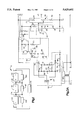
- FIG. 2 is a block diagram of the preferred embodiment of the system charger.
- system charger 14 charges all batteries in the system 12A-12C with high current. However, when the battery system's overall voltage is below a set value (typically 70% of cut-off voltage) or above a set value (typically 85% of full charge), system charger 14 switches to restricted charge. Also, system charger 14 will periodically interrupt main charge on a preset timed basis and signal (via the opto-couplers 110) battery chargers 16A-16C to do the same for various intervals, while system charger 14 will partially discharge the batteries 12A-12C.
- a set value typically 70% of cut-off voltage
- a set value typically 85% of full charge
- Main power supply section 18 is powered by line current and has a V + output which is connected to the positive terminal of the string of batteries 12A-12C at B + .
- Power supply section 18 has a V - output, defined as ground, connected to the negative terminal of batteries 12A-12C at B - .
- the gate input 36 controls the current flowing into V - , the high current for fast charge approximately C/5 in this example) when gate input 36 is high, and trickle charge (typically C/500) when gate input 36 is low.
- Gate control section 34 controls the battery charging rate (for either fast charge or slow charge) via gate input 36.
- Gate control section 34 is connected to high battery turn-off section 40, low battery turn-off section 19, timed discharge section 38, and timed turn-off section 22.
- the gate control section 34 essentially "OR"s the output of sections 40, 19, 38 and 22 to switch power supply 18 from fast charge to slow charge when either the output of high battery turn-off 19 goes high, or the output of any of the other sections 40, 38 and 22 goes low.
- the main power section 18 is otherwise set for fast charge.
- Voltage divider 21 outputs a voltage proportional to overall battery voltage B + -B - .
- Voltage reference section 17 outputs two different stable, reference voltages.
- a first reference voltage corresponds to a "low battery” voltage, i.e. about 70% of the cut-off voltage of the string of batteries 12A-12C, below which the system charger 14 might be damaged by sustained overload.
- a second reference voltage corresponds to a "high battery” voltage, i.e. about 85% state-of charge of the string of lead-acid batteries 12A-12C, above which the smaller "sub-chargers" 16A-16C are intended to complete the charging cycle.
- Low battery turn-off section 19 compares the overall battery voltage B + --B - with the first reference voltage.
- the output of low battery turn-off section 19 is low when the battery voltage is below the first low reference voltage.
- the low output shifts the main power supply 18 from a fast charge to a small charge. This provides a safe "walk in” charge rate for batteries having a very low voltage.
- low battery turn-off section 19 enables fast charging by pulling its output high which in turn permits the output of gate control section 34 to go high.
- High battery turn-off section 40 compares the battery voltage with the second higher reference voltage.
- the output of high battery turn-off section 40 is low when the overall battery voltage B + -B - is below the second high reference voltage, thus enabling fast charging if not inhibited by turn off section 19, timed discharge section 38, or timed turn-off section 22.
- section 40 causes the main power supply 18 to shift from fast charging to trickle charging, by turning off the output of section 40 which, in turn, removes the output of gate controller 34 at gate input 36.
- Opto-coupler 110 is the communication interface between system charger 14 and the individual battery chargers 16A-16C. Opto-coupler 110 is activated by timed discharge section 38 and timed turn-off section 22 to turn off battery chargers 16A-16C.
- timed discharge section 38 is controlled by an internal counter. At various intervals for various durations, timed discharge section 38 turns off main power supply 18 (by switching its output to gate control section 34 from high to low), activates the opto-coupler 110, and sends a discharge current through the batteries 12A-12C.
- timed turn-off section 22 is controlled by an internal counter. At various intervals for various durations, timed turn-off section 22 causes main power supply section 18 to switch from fast charge to trickle charge by switching its output to the gate control 34 from high to low and activating opto-coupler 110.
- the auxiliary power supply 20 powers gate control 34, high battery turn-off 40, and low battery turn-off 19.
- Auxiliary power supply 20 has much lower power capacity than the main power supply 18 because logic circuitry requires much less power than battery charging. Unlike the main power supply 18, its output is continuous and a portion is filtered. The output of auxiliary power supply 20 is filtered by filter section 101. The filtered output powers timed discharge 38 and timed turn-off 22 with filtered, uninterrupted power at their V + .
- the V - power inputs of each section in the system 10 are connected together at B- which is defined as system ground, or common.
- the main power supply section 18 includes a main transformer 24, with a center-tapped secondary.
- transformer 24 can have a 90 V center-tapped secondary capable of providing approximately 40 VDC at 20 amperes.
- the output from transformer 24 is rectified by Screwiest 30 and 32 whenever the gate control section 34 turns on 30 and 32 through line 36.
- Diodes 70 and 72 direct the control current from gate control section 34 to Scars 30 or 32.
- Resistors 74 and 76 are high temperature leakage current protectors for Scars 30 and 32.
- Diodes 78 and 80 provide rectified "walk-in” or trickle current through resistors 82, 84, and 86 when Scars 30 and 32 are off. Therefore, resistors 82, 84 and 86 provide initial start-up or "walk-in” current when the overall battery voltage B + -B - is below the safe lower limit of charger operation, as described below.
- transistor 62 conducts whenever its base is brought low, thereby turning on fast charge.
- Light emitting diode (LED) 88 in series with resistor 90 displays the status of power flowing to SCREWIEST drives 30 and 32.
- Zener diode 92 in the gate control serves to provide gate control current if diode 88 should fail and create an open circuit.
- Resistor 94 shunts a portion of the current through resistor 90 to bypass LED 88 if the current is beyond the safe limit of LED 88.
- gate control section 34 The power provided to gate control section 34 is unfiltered and operates synchronously with the A.C. line. This is satisfactory, since gate current to turn on transistor 62 is only required off zero crossing. Near zero crossing, transistor 62 is always off since the output of comparator 39 is unavailable since no power is available to operate the output of comparator 39.
- the auxiliary power supply section 20 includes a small transformer 63 with a center-tapped secondary.
- transformer 63 can be a 20 V center-tapped secondary rated for 100-300 milliamps.
- zener diode 48 In voltage reference section 17, zener diode 48, having a low voltage rating with a negative temperature coefficient, maintains a stable reference voltage irrespective of current changes from the batteries 12A-12C. This reference voltage corresponds to "low battery” voltage.
- the added forward voltage drop of diode 50 provides another stable reference voltage corresponding to "high battery” voltage. Diodes 48 and 50 are powered by current through resistor 52.
- comparator 39 compares the "high battery” reference voltage to the overall battery voltage B + -B - proportionally reduced through resistor divider 54, 56, and 58. In operation, when the overall battery voltage B + -B - is below the "high battery” reference voltage, the output of comparator 39 goes low to turn on transistor 62 by providing current through resistor 60. Resistor 64 acts as a high temperature leakage control resistor. Transistor 62 then sends current through LED 88 (thereby lighting it) and resistors 94 and 90 and diodes 70 and 72. Finally the current from transistor 62 is delivered to the gates of SCRs 30 and 32 to turn them on, which then completes current from the battery B - for fast charging the battery system.
- Transistor 68 is a clamp to cut off drive current to SCRs 30 and 32.
- Resistor 66 is the high temperature leakage control resistor for transistor 68.
- comparator 112 compares the "low battery” reference voltage to the overall battery voltage B + -B - , proportionally reduced through resistor divider 54, 56, and 58. In operation, when overall battery voltage B + -B - is below the "low battery” threshold voltage, the output of comparator 112 goes low, pulling current through diode 116 and resistor 114 to provide current to the base of transistor 68. Transistor 68 is thereby turned on, and it clamps the base of transistor 62 off, thereby turning it off and halting the current flow to the gates of SCRs 30 and 32.
- SCRs 30 and 32 also turn off, and only a restricted current through resistors 82, 84 and 86 charges the string of batteries. This prevents system charger 14 from overheating and provides a safe "walk-in” current until the system voltage reaches a safe level.
- filter section 101 regulates and filters the voltage from auxiliary power supply 20 to power turn-off sections 22 and 38.
- LED 96 and series current control resistor 98 display A.C. power.
- Diode 100 isolates capacitor 102 the primary power supply filter for control section 22, timed discharge section 38 and O.C + .
- Resistor 104, zener diode 106, and capacitor 108 form a regulated power source.
- capacitor 102 provides a power source for the input diodes of the opto-couplers 110 used to transmit shut down instructions to the individual battery chargers 16A-16C, as discussed below.
- Timed sections 38 and 22 are controlled by 4060 CMOS counter integrated circuits 114 and 116 consisting of 14 stage binary counters preceded by two accessible sequential input inverters, ganged together.
- Resistors 118 and 120 form a voltage divider which provides a 120 hz input from the A.C. auxiliary power supply line to the input of counter 114.
- Diodes 122 and 124 provide offset compensation to prevent input PI of integrated circuit 114 from exceeding VDD by more than a few millivolts.
- Capacitor 126 is a noise filter.
- FET 128 receives an approximate 1 millisecond (duration) pulse centered on each A.C. line zero crossing from the output of the first input inverter PO of counter 114 through diode 156.
- FET 128 responds to the voltage at the gate, it conducts current so that A) battery discharge current is drawn from the B + side of the string of batteries 12A-12C through resistors 130 and 132, B) SCRs 30 and 32 are inhibited through diode 134, resistor 114, transistor 68, transistor 62, etc., C) the negative output of opto-coupler 110 is activated through diode 136.
- Diodes 142, 144, 146, and 148 combine to pull down the voltage from pull-up resistor 150, which independently turns on FET 128 through diode 152. Resistor 154 pulls down the gate of FET 128 when neither diodes 156 nor 152 provide a positive input. Since counter 114 does not provide a Q11 output for diode 142, Q10 is used instead. The result is two, roughly two-second pulses separated by roughly two seconds every approximately two minutes, instead of a single four second pulse in the example shown.
- counter 116 counts the output of counter 114. After every 2 13 counts (approximately 350 hours), timed turn-off section 38 will turn on transistor 160 through resistor 162 and transistor 163 which will, in turn: A) turn off SCRs 30 and 32 through resistor 114, transistor 68, and transistor 62 via diode 156; and B) operate the negative input of opto-coupler 110 through diode 164.
- Diode 166 is a clamp on the reset of counter 116 through resistor 168 and noise filter capacitor 170 until output Q14 of counter 116 is positive. Note that FET 128 is not operated by counter 116. Therefore, the string of batteries 12A-12C are not discharged and "rest” with only "trickle charge” flowing. This illustrates that pulse patterns involving different durations and repetition rates and providing both discharge and rest periods may be easily implemented.
- output Q9 goes positive resetting counter 116 and returning system 10 to normal operation.
- the values shown are actually suitable for long term standby operation.
- the input to counter 116 would be taken from the Q6 output of counter 114 reducing the cycle time approximately 1 hour and the "rest" to approximately 2 minutes. While this is not sufficient time for full re-equilibration, it represents an example of an effective and efficient compromise.
- FIG. 4 there is shown a schematic of an individual battery charger 16A.
- Each battery 12A-12C in the system 10 has its own such battery charger 16A-16C connected to each of the serially connected batteries 12A-12C. Since the individual battery chargers 16A-16C are substantially identical, only one charger 16A is discussed in detail.
- the system charger 14 signals the battery chargers to stop fast charging leaving only trickle charging in operation via the opto-coupler 110 provided in the circuitry of each battery charger 16A-16C.
- Each battery charger 12A monitors battery voltage of the specific battery across which it is attached.
- Each battery is charged with a restricted current when that specific battery voltage is either below a minimum, or above a maximum, or when system charger 14 signals it to do so by powering the daisy-chained opto-couplers 110. Otherwise, charger 12A charges the battery at a normal rate.
- the power supply section 189 includes an isolated A.C. line transformer 190 with a center-tapped secondary, typically having a voltage of 30 V.
- Parallel diodes 192, 194, 196, and 198 provide full-wave rectification.
- Diodes 214 and 216 similarly provide a full wave rectified "offset" or "auxiliary" power source of opposite polarity to the main power source.
- the rectifier branch that carries the greater current has diodes shown in parallel pairs to increase current capacity.
- a resistor divider 243 comprised of resistors 244, 242 and 240, provides a voltage (proportional to battery voltage B + -B - ) to comparator 228.
- Zener diode 238 and resistor 246 provide a stable reference voltage corresponding to high-battery cutoff voltage.
- Resistor 212 is the high temperature leakage control resistor for SCR 200.
- Opto-coupler 110 enables the system battery charger 14 to override the comparator process described above.
- Each battery charger 16A-16C has its own opto-coupler 110A. 110B, 110C, respectively, comprising a current limiting resistor 184, an LED 182, and a photo transistor 252 and leakage control resistor 254.
- the opto-couplers 110A-110C of successive battery chargers 16A-16C are daisy-chained in parallel, so that system charger 14 controls all of them simultaneously.
- Each opto-coupler 110a-110C input section has twin connectors, i.e., 111A, 113A which are daisy chained together. Therefore, all the opto inputs are connected to O.C. + and O.C. - .
- Resistor 248 provides sufficient impedance for the output of photo-transistor 252 and leakage control resistor 254, to clamp the non-inverting input of 228 (in response to signals issued by the system charger timing system) and remove the drive to SCR 200.
- Zener diode 210 conducts some of the current in case LED 206 should fail and leave an open circuit.
- Resistor 212 provides thermal leakage current control for SCR 200.
- LED 218 with current limiting resistor 220 indicates when the circuit is powered.
- Diode 252 provides reverse battery polarity isolation.
- the off-set supply also powers comparator 228 with diodes 226 and 229 to provide reverse battery installation protection and preventing any power from being drawn from the battery 16A, if A.C. power is lacking.
- This function is duplicated by diodes 230, 232, and 234 which are connected in parallel for thermal design convenience. Diodes 230, 232, and 234 isolate battery charger 16A from the system charger 14 if the battery 14A connected to battery charger 16A were to become disconnected or fail with an open circuit.
- the system charger would be adjusted to a cut-off charge of perhaps 2.23 to 2.27 V per cell, with the "subcharger" battery voltage set to 2.30 V per cell. Since 24 hours is generally allowed for substantial recharge, the individual battery chargers could be relatively small.
- the system charger 14 would typically be in the C/20 range or smaller and the individual battery chargers C/40 or smaller.
- the compound charge concept is sufficiently flexible to allow systems to be configured in a cost effective configuration to meet individual requirements. This might vary form a single battery system charger acting as a stand-alone providing a triple pulse pattern to enhance cycle or standby performance, to a low cost system where a single "sub-battery” charger is used stand-alone to charge one or more batteries, to very large systems in which several compound chargers might be combined to charge subsets of a very high voltage battery system "piece-wise", i.e. a "multiple compounded" system. In a sense, a compound charger system or even a compound/compound system could be applied.
Abstract
Description
Claims (32)
Priority Applications (1)
| Application Number | Priority Date | Filing Date | Title |
|---|---|---|---|
| US08/228,874 US5629601A (en) | 1994-04-18 | 1994-04-18 | Compound battery charging system |
Applications Claiming Priority (1)
| Application Number | Priority Date | Filing Date | Title |
|---|---|---|---|
| US08/228,874 US5629601A (en) | 1994-04-18 | 1994-04-18 | Compound battery charging system |
Publications (1)
| Publication Number | Publication Date |
|---|---|
| US5629601A true US5629601A (en) | 1997-05-13 |
Family
ID=22858885
Family Applications (1)
| Application Number | Title | Priority Date | Filing Date |
|---|---|---|---|
| US08/228,874 Expired - Lifetime US5629601A (en) | 1994-04-18 | 1994-04-18 | Compound battery charging system |
Country Status (1)
| Country | Link |
|---|---|
| US (1) | US5629601A (en) |
Cited By (62)
| Publication number | Priority date | Publication date | Assignee | Title |
|---|---|---|---|---|
| US5847542A (en) * | 1993-09-17 | 1998-12-08 | Nec Corporation | Circuit for preventing overdischarge of rechargeable battery pack consisting of a plurality of rechargeable batteries |
| US5896024A (en) * | 1998-03-24 | 1999-04-20 | Black & Decker, Inc. | Method and apparatus for manually selecting battery charging process |
| US5955868A (en) * | 1997-03-21 | 1999-09-21 | Sanyo Electric Co., Ltd. | Battery charging apparatus having battery attachment sections for charging batteries at different rates or timing |
| US6097174A (en) * | 1998-09-18 | 2000-08-01 | Yang; Tai-Her | Individually adjustable type automatic charging circuit for multiple batteries |
| US6160375A (en) * | 1998-05-14 | 2000-12-12 | Nissan Motor Co., Ltd. | Charge controlling device and method for multi-cell battery, and electric vehicle provided with change controlling |
| US6396244B2 (en) * | 2000-04-07 | 2002-05-28 | Toyota Jidosha Kabushiki Kaisha | Electric element control apparatus, battery system, and inverter motor system |
| US6465986B1 (en) | 1998-12-11 | 2002-10-15 | Planet Electric, Inc. | Battery network with compounded interconnections |
| WO2003030331A1 (en) * | 2001-10-03 | 2003-04-10 | Trojan Battery Company | System and method for battery charging |
| US6573687B2 (en) * | 1998-11-24 | 2003-06-03 | Matsushita Electric Industrial Co., Ltd. | Charging/discharging control method for secondary battery |
| US6678132B1 (en) * | 2002-09-06 | 2004-01-13 | Bae Systems Controls, Inc. | Ground fault detection system |
| US20050024001A1 (en) * | 2002-02-27 | 2005-02-03 | Donnelly Frank Wegner | Method for monitoring and controlling traction motors in locomotives |
| US20050189886A1 (en) * | 2004-02-17 | 2005-09-01 | Railpower Technologies Corp. | Predicting wheel slip and skid in a locomotive |
| US20050251299A1 (en) * | 2004-03-30 | 2005-11-10 | Railpower Technologies Corp. | Emission management for a hybrid locomotive |
| US20050269995A1 (en) * | 2004-05-17 | 2005-12-08 | Railpower Technologies Corp. | Design of a Large battery pack for a hybrid locomotive |
| US20050279242A1 (en) * | 2004-03-01 | 2005-12-22 | Railpower Technologies Corp. | Cabless hybrid locomotive |
| US20060061307A1 (en) * | 2004-08-09 | 2006-03-23 | Donnelly Frank W | Locomotive power train architecture |
| US20060076171A1 (en) * | 2004-08-09 | 2006-04-13 | Donnelly Frank W | Regenerative braking methods for a hybrid locomotive |
| US20060091832A1 (en) * | 2004-09-03 | 2006-05-04 | Donnelly Frank W | Multiple engine locomotive configuration |
| US20060146454A1 (en) * | 2002-11-05 | 2006-07-06 | Donnelly Frank W | Direct turbogenerator |
| US20060158037A1 (en) * | 2005-01-18 | 2006-07-20 | Danley Douglas R | Fully integrated power storage and supply appliance with power uploading capability |
| US7124691B2 (en) | 2003-08-26 | 2006-10-24 | Railpower Technologies Corp. | Method for monitoring and controlling locomotives |
| US20060266044A1 (en) * | 2005-04-25 | 2006-11-30 | Frank Donnelly | Alternator boost method |
| US20060276938A1 (en) * | 2005-06-06 | 2006-12-07 | Equinox Energy Solutions, Inc. | Optimized energy management system |
| EP1777804A1 (en) * | 2005-10-19 | 2007-04-25 | General Electric Company | Battery charging system for charging a plurality of batteries |
| US20070144804A1 (en) * | 2005-10-19 | 2007-06-28 | Railpower Technologies, Corp. | Design of a large low maintenance battery pack for a hybrid locomotive |
| US20070203860A1 (en) * | 2006-02-24 | 2007-08-30 | Gridpoint, Inc. | Energy budget manager |
| US20070271006A1 (en) * | 2006-05-18 | 2007-11-22 | Gridpoint, Inc. | Modular energy control system |
| US20090269217A1 (en) * | 2008-03-28 | 2009-10-29 | Senthilkumar Vijayakumar | System and Method for Portable Battery Back-Up Sump Pump |
| WO2010123726A2 (en) | 2009-04-20 | 2010-10-28 | Valence Technology, Inc. | Battery chargers, electrical systems, and rechargeable battery charging methods |
| US20110057659A1 (en) * | 2009-09-04 | 2011-03-10 | Yazaki Corporation | Voltage measuring device |
| US20110074350A1 (en) * | 2009-09-29 | 2011-03-31 | Kocher Mark J | Kiosk vehicle charging and selecting systems |
| US20110234148A1 (en) * | 2010-03-23 | 2011-09-29 | Chi-Long Wen | Battery charging device with multiple power sources |
| US20120043760A1 (en) * | 2009-05-05 | 2012-02-23 | Ssb Wind Systems Gmbh & Co. Kg | Emergency power supply device |
| RU2444818C1 (en) * | 2010-06-18 | 2012-03-10 | Открытое акционерное общество "Информационные спутниковые системы" им. акад. М.Ф. Решетнёва" | Method for operation of nickel-hydrogen accumulator battery included into artificial earth satellite |
| RU2450391C1 (en) * | 2010-12-15 | 2012-05-10 | Открытое акционерное общество "Информационные спутниковые системы" имени академика М.Ф. Решетнева" | Method of nickel-hydrogen accumulator preparation for normal operation with man-made satellites |
| WO2012034670A3 (en) * | 2010-09-15 | 2012-09-20 | Audi Ag | Method for charging a battery of a motor vehicle |
| RU2465695C1 (en) * | 2011-04-01 | 2012-10-27 | Открытое акционерное общество "Информационные спутниковые системы" имени академика М.Ф. Решетнёва" | METHOD TO OPERATE NICKEL-HYDROGEN ACCUMULATOR BATTERY FROM n SERIALLY CONNECTED ACCUMULATORS WITHIN ARTIFICIAL EARTH SATELLITE |
| RU2488933C2 (en) * | 2011-10-13 | 2013-07-27 | Открытое акционерное общество "Информационные спутниковые системы" имени академика М.Ф. Решетнева" | Space vehicle electric power supply method |
| US20140028267A1 (en) * | 2012-07-26 | 2014-01-30 | Samsung Sdl Co., Ltd. | Battery charging method and battery pack utilizing the same |
| CN103603768A (en) * | 2013-11-06 | 2014-02-26 | 北京天诚同创电气有限公司 | Variable pitch control system and charging management control method of high-power wind generating set |
| US20140055085A1 (en) * | 2012-02-23 | 2014-02-27 | Cymbet Corporation | Thin film battery charge control and method |
| US20140152099A1 (en) * | 2012-04-27 | 2014-06-05 | Logiquip, Llc | Mobile cart and power system therfor |
| US9248825B2 (en) | 2007-05-16 | 2016-02-02 | General Electric Company | Method of operating vehicle and associated system |
| US9277191B2 (en) | 2012-12-12 | 2016-03-01 | Schneider Electric USA, Inc. | Security monitoring systems, methods and devices for electric vehicle charging stations |
| US9328727B2 (en) | 2003-12-08 | 2016-05-03 | Pentair Water Pool And Spa, Inc. | Pump controller system and method |
| US9383244B2 (en) | 2012-10-25 | 2016-07-05 | Pentair Flow Technologies, Llc | Fluid level sensor systems and methods |
| US9404500B2 (en) | 2004-08-26 | 2016-08-02 | Pentair Water Pool And Spa, Inc. | Control algorithm of variable speed pumping system |
| US9441632B2 (en) | 2012-10-25 | 2016-09-13 | Pentair Flow Technologies, Llc | Sump pump remote monitoring systems and methods |
| US9551344B2 (en) | 2004-08-26 | 2017-01-24 | Pentair Water Pool And Spa, Inc. | Anti-entrapment and anti-dead head function |
| US9556874B2 (en) | 2009-06-09 | 2017-01-31 | Pentair Flow Technologies, Llc | Method of controlling a pump and motor |
| US9568005B2 (en) | 2010-12-08 | 2017-02-14 | Pentair Water Pool And Spa, Inc. | Discharge vacuum relief valve for safety vacuum release system |
| US9712098B2 (en) | 2009-06-09 | 2017-07-18 | Pentair Flow Technologies, Llc | Safety system and method for pump and motor |
| US9726184B2 (en) | 2008-10-06 | 2017-08-08 | Pentair Water Pool And Spa, Inc. | Safety vacuum release system |
| US9777733B2 (en) | 2004-08-26 | 2017-10-03 | Pentair Water Pool And Spa, Inc. | Flow control |
| US9885360B2 (en) | 2012-10-25 | 2018-02-06 | Pentair Flow Technologies, Llc | Battery backup sump pump systems and methods |
| US9932984B2 (en) | 2004-08-26 | 2018-04-03 | Pentair Water Pool And Spa, Inc. | Pumping system with power optimization |
| RU2661187C1 (en) * | 2017-07-17 | 2018-07-12 | Российская Федерация, от имени которой выступает Министерство обороны Российской Федерации | Method of ground environment of spacecraft power supply system accumulator batteries |
| US10240606B2 (en) | 2004-08-26 | 2019-03-26 | Pentair Water Pool And Spa, Inc. | Pumping system with two way communication |
| US10731655B2 (en) | 2004-08-26 | 2020-08-04 | Pentair Water Pool And Spa, Inc. | Priming protection |
| US10871001B2 (en) | 2004-08-26 | 2020-12-22 | Pentair Water Pool And Spa, Inc. | Filter loading |
| US10947981B2 (en) | 2004-08-26 | 2021-03-16 | Pentair Water Pool And Spa, Inc. | Variable speed pumping system and method |
| WO2024040955A1 (en) * | 2022-08-22 | 2024-02-29 | 中国华能集团清洁能源技术研究院有限公司 | Method for automatically adjusting charging voltage and power of energy storage system, system and storage medium |
Citations (4)
| Publication number | Priority date | Publication date | Assignee | Title |
|---|---|---|---|---|
| US4331911A (en) * | 1978-05-22 | 1982-05-25 | Park Robert H | Method of equalizing the voltages of the individual cells of storage batteries |
| US5003244A (en) * | 1989-05-09 | 1991-03-26 | Digital Equipment Corporation | Battery charger for charging a plurality of batteries |
| US5162663A (en) * | 1990-09-28 | 1992-11-10 | Ncr Corporation | Selective output disconnect for a single transformer converter |
| US5523668A (en) * | 1994-04-15 | 1996-06-04 | Feldstein; Robert S. | NiCd/NiMH battery charger |
-
1994
- 1994-04-18 US US08/228,874 patent/US5629601A/en not_active Expired - Lifetime
Patent Citations (4)
| Publication number | Priority date | Publication date | Assignee | Title |
|---|---|---|---|---|
| US4331911A (en) * | 1978-05-22 | 1982-05-25 | Park Robert H | Method of equalizing the voltages of the individual cells of storage batteries |
| US5003244A (en) * | 1989-05-09 | 1991-03-26 | Digital Equipment Corporation | Battery charger for charging a plurality of batteries |
| US5162663A (en) * | 1990-09-28 | 1992-11-10 | Ncr Corporation | Selective output disconnect for a single transformer converter |
| US5523668A (en) * | 1994-04-15 | 1996-06-04 | Feldstein; Robert S. | NiCd/NiMH battery charger |
Cited By (121)
| Publication number | Priority date | Publication date | Assignee | Title |
|---|---|---|---|---|
| US5847542A (en) * | 1993-09-17 | 1998-12-08 | Nec Corporation | Circuit for preventing overdischarge of rechargeable battery pack consisting of a plurality of rechargeable batteries |
| US5955868A (en) * | 1997-03-21 | 1999-09-21 | Sanyo Electric Co., Ltd. | Battery charging apparatus having battery attachment sections for charging batteries at different rates or timing |
| US5896024A (en) * | 1998-03-24 | 1999-04-20 | Black & Decker, Inc. | Method and apparatus for manually selecting battery charging process |
| US6160375A (en) * | 1998-05-14 | 2000-12-12 | Nissan Motor Co., Ltd. | Charge controlling device and method for multi-cell battery, and electric vehicle provided with change controlling |
| US6097174A (en) * | 1998-09-18 | 2000-08-01 | Yang; Tai-Her | Individually adjustable type automatic charging circuit for multiple batteries |
| US6573687B2 (en) * | 1998-11-24 | 2003-06-03 | Matsushita Electric Industrial Co., Ltd. | Charging/discharging control method for secondary battery |
| US6465986B1 (en) | 1998-12-11 | 2002-10-15 | Planet Electric, Inc. | Battery network with compounded interconnections |
| US6396244B2 (en) * | 2000-04-07 | 2002-05-28 | Toyota Jidosha Kabushiki Kaisha | Electric element control apparatus, battery system, and inverter motor system |
| WO2003030331A1 (en) * | 2001-10-03 | 2003-04-10 | Trojan Battery Company | System and method for battery charging |
| US20050017684A1 (en) * | 2001-10-03 | 2005-01-27 | Brecht William B | System and method for battery charging |
| US7129675B2 (en) | 2001-10-03 | 2006-10-31 | Trojan Battery Company | System and method for battery charging |
| US20050264245A1 (en) * | 2002-02-27 | 2005-12-01 | Railpower Technologies Corp. | Method for monitoring and controlling traction motors in locomotives |
| US20050024001A1 (en) * | 2002-02-27 | 2005-02-03 | Donnelly Frank Wegner | Method for monitoring and controlling traction motors in locomotives |
| US6984946B2 (en) | 2002-02-27 | 2006-01-10 | Railpower Technologies Corp. | Method for monitoring and controlling traction motors in locomotives |
| US6678132B1 (en) * | 2002-09-06 | 2004-01-13 | Bae Systems Controls, Inc. | Ground fault detection system |
| US20060146454A1 (en) * | 2002-11-05 | 2006-07-06 | Donnelly Frank W | Direct turbogenerator |
| US7124691B2 (en) | 2003-08-26 | 2006-10-24 | Railpower Technologies Corp. | Method for monitoring and controlling locomotives |
| US10289129B2 (en) | 2003-12-08 | 2019-05-14 | Pentair Water Pool And Spa, Inc. | Pump controller system and method |
| US9328727B2 (en) | 2003-12-08 | 2016-05-03 | Pentair Water Pool And Spa, Inc. | Pump controller system and method |
| US10642287B2 (en) | 2003-12-08 | 2020-05-05 | Pentair Water Pool And Spa, Inc. | Pump controller system and method |
| US10416690B2 (en) | 2003-12-08 | 2019-09-17 | Pentair Water Pool And Spa, Inc. | Pump controller system and method |
| US10409299B2 (en) | 2003-12-08 | 2019-09-10 | Pentair Water Pool And Spa, Inc. | Pump controller system and method |
| US9399992B2 (en) | 2003-12-08 | 2016-07-26 | Pentair Water Pool And Spa, Inc. | Pump controller system and method |
| US10241524B2 (en) | 2003-12-08 | 2019-03-26 | Pentair Water Pool And Spa, Inc. | Pump controller system and method |
| US7084602B2 (en) | 2004-02-17 | 2006-08-01 | Railpower Technologies Corp. | Predicting wheel slip and skid in a locomotive |
| US20050206230A1 (en) * | 2004-02-17 | 2005-09-22 | Railpower Technologies Corp. | Managing wheel slip in a locomotive |
| US20050189886A1 (en) * | 2004-02-17 | 2005-09-01 | Railpower Technologies Corp. | Predicting wheel slip and skid in a locomotive |
| US7064507B2 (en) | 2004-02-17 | 2006-06-20 | Railpower Technologies Corp. | Managing wheel skid in a locomotive |
| US7467830B2 (en) | 2004-02-17 | 2008-12-23 | Railpower Technologies Corp. | Managing wheel slip in a locomotive |
| US20050279242A1 (en) * | 2004-03-01 | 2005-12-22 | Railpower Technologies Corp. | Cabless hybrid locomotive |
| US20050251299A1 (en) * | 2004-03-30 | 2005-11-10 | Railpower Technologies Corp. | Emission management for a hybrid locomotive |
| US7349797B2 (en) | 2004-03-30 | 2008-03-25 | Railpower Technologies Corp | Emission management for a hybrid locomotive |
| US20050269995A1 (en) * | 2004-05-17 | 2005-12-08 | Railpower Technologies Corp. | Design of a Large battery pack for a hybrid locomotive |
| US7507500B2 (en) | 2004-05-17 | 2009-03-24 | Railpower Technologies Corp. | Design of a large battery pack for a hybrid locomotive |
| US20060012334A1 (en) * | 2004-05-17 | 2006-01-19 | Railpower Technologies Corp. | Automated battery cell shunt bypass |
| US20060076171A1 (en) * | 2004-08-09 | 2006-04-13 | Donnelly Frank W | Regenerative braking methods for a hybrid locomotive |
| US7940016B2 (en) | 2004-08-09 | 2011-05-10 | Railpower, Llc | Regenerative braking methods for a hybrid locomotive |
| US7304445B2 (en) | 2004-08-09 | 2007-12-04 | Railpower Technologies Corp. | Locomotive power train architecture |
| US20060061307A1 (en) * | 2004-08-09 | 2006-03-23 | Donnelly Frank W | Locomotive power train architecture |
| US10527042B2 (en) | 2004-08-26 | 2020-01-07 | Pentair Water Pool And Spa, Inc. | Speed control |
| US11073155B2 (en) | 2004-08-26 | 2021-07-27 | Pentair Water Pool And Spa, Inc. | Pumping system with power optimization |
| US10415569B2 (en) | 2004-08-26 | 2019-09-17 | Pentair Water Pool And Spa, Inc. | Flow control |
| US9777733B2 (en) | 2004-08-26 | 2017-10-03 | Pentair Water Pool And Spa, Inc. | Flow control |
| US10502203B2 (en) | 2004-08-26 | 2019-12-10 | Pentair Water Pool And Spa, Inc. | Speed control |
| US10731655B2 (en) | 2004-08-26 | 2020-08-04 | Pentair Water Pool And Spa, Inc. | Priming protection |
| US10871001B2 (en) | 2004-08-26 | 2020-12-22 | Pentair Water Pool And Spa, Inc. | Filter loading |
| US10871163B2 (en) | 2004-08-26 | 2020-12-22 | Pentair Water Pool And Spa, Inc. | Pumping system and method having an independent controller |
| US9605680B2 (en) | 2004-08-26 | 2017-03-28 | Pentair Water Pool And Spa, Inc. | Control algorithm of variable speed pumping system |
| US9932984B2 (en) | 2004-08-26 | 2018-04-03 | Pentair Water Pool And Spa, Inc. | Pumping system with power optimization |
| US9551344B2 (en) | 2004-08-26 | 2017-01-24 | Pentair Water Pool And Spa, Inc. | Anti-entrapment and anti-dead head function |
| US10240604B2 (en) | 2004-08-26 | 2019-03-26 | Pentair Water Pool And Spa, Inc. | Pumping system with housing and user interface |
| US10240606B2 (en) | 2004-08-26 | 2019-03-26 | Pentair Water Pool And Spa, Inc. | Pumping system with two way communication |
| US10947981B2 (en) | 2004-08-26 | 2021-03-16 | Pentair Water Pool And Spa, Inc. | Variable speed pumping system and method |
| US11391281B2 (en) | 2004-08-26 | 2022-07-19 | Pentair Water Pool And Spa, Inc. | Priming protection |
| US10480516B2 (en) | 2004-08-26 | 2019-11-19 | Pentair Water Pool And Spa, Inc. | Anti-entrapment and anti-deadhead function |
| US9404500B2 (en) | 2004-08-26 | 2016-08-02 | Pentair Water Pool And Spa, Inc. | Control algorithm of variable speed pumping system |
| US20060091832A1 (en) * | 2004-09-03 | 2006-05-04 | Donnelly Frank W | Multiple engine locomotive configuration |
| US7565867B2 (en) | 2004-09-03 | 2009-07-28 | Frank Wegner Donnelly | Multiple engine locomotive configuration |
| US20060158037A1 (en) * | 2005-01-18 | 2006-07-20 | Danley Douglas R | Fully integrated power storage and supply appliance with power uploading capability |
| US7309929B2 (en) | 2005-04-25 | 2007-12-18 | Railpower Technologies Corporation | Locomotive engine start method |
| US20060266044A1 (en) * | 2005-04-25 | 2006-11-30 | Frank Donnelly | Alternator boost method |
| US7518254B2 (en) | 2005-04-25 | 2009-04-14 | Railpower Technologies Corporation | Multiple prime power source locomotive control |
| US7514807B2 (en) | 2005-04-25 | 2009-04-07 | Railpower Technologies Corp. | Alternator boost method |
| US7783390B2 (en) | 2005-06-06 | 2010-08-24 | Gridpoint, Inc. | Method for deferring demand for electrical energy |
| US20110208365A1 (en) * | 2005-06-06 | 2011-08-25 | Craig Howard Miller | Optimized energy management system |
| US20060276938A1 (en) * | 2005-06-06 | 2006-12-07 | Equinox Energy Solutions, Inc. | Optimized energy management system |
| US8903560B2 (en) * | 2005-06-06 | 2014-12-02 | Gridpoint, Inc. | Optimized energy management system |
| US7274975B2 (en) | 2005-06-06 | 2007-09-25 | Gridpoint, Inc. | Optimized energy management system |
| US20070276547A1 (en) * | 2005-06-06 | 2007-11-29 | Gridpoint, Inc. | Optimized Energy Management System |
| EP2267861A1 (en) * | 2005-10-19 | 2010-12-29 | General Electric Company | Battery charging system for charging a plurality of batteries |
| US20070090797A1 (en) * | 2005-10-19 | 2007-04-26 | Glosser Richard J Jr | Battery charging system and method of operating same |
| EP1777804A1 (en) * | 2005-10-19 | 2007-04-25 | General Electric Company | Battery charging system for charging a plurality of batteries |
| JP2007116892A (en) * | 2005-10-19 | 2007-05-10 | General Electric Co <Ge> | Battery-charging system and method for operating the same |
| US7642748B2 (en) | 2005-10-19 | 2010-01-05 | General Electric Company | Battery charging system and method of operating same |
| US20070144804A1 (en) * | 2005-10-19 | 2007-06-28 | Railpower Technologies, Corp. | Design of a large low maintenance battery pack for a hybrid locomotive |
| US7661370B2 (en) | 2005-10-19 | 2010-02-16 | Railpower, Llc | Design of a large low maintenance battery pack for a hybrid locomotive |
| US20070203860A1 (en) * | 2006-02-24 | 2007-08-30 | Gridpoint, Inc. | Energy budget manager |
| US8103389B2 (en) | 2006-05-18 | 2012-01-24 | Gridpoint, Inc. | Modular energy control system |
| US20070271006A1 (en) * | 2006-05-18 | 2007-11-22 | Gridpoint, Inc. | Modular energy control system |
| US9248825B2 (en) | 2007-05-16 | 2016-02-02 | General Electric Company | Method of operating vehicle and associated system |
| US10718338B2 (en) | 2008-03-28 | 2020-07-21 | Pentair Flow Technologies, Llc | System and method for portable battery back-up sump pump |
| US8579600B2 (en) | 2008-03-28 | 2013-11-12 | Sta-Rite Industries, Llc | System and method for portable battery back-up sump pump |
| US9816507B2 (en) | 2008-03-28 | 2017-11-14 | Pentair Flow Technologies, Llc | Wheeled kit for battery-powered back-up sump pump |
| US20090269217A1 (en) * | 2008-03-28 | 2009-10-29 | Senthilkumar Vijayakumar | System and Method for Portable Battery Back-Up Sump Pump |
| US10724263B2 (en) | 2008-10-06 | 2020-07-28 | Pentair Water Pool And Spa, Inc. | Safety vacuum release system |
| US9726184B2 (en) | 2008-10-06 | 2017-08-08 | Pentair Water Pool And Spa, Inc. | Safety vacuum release system |
| EP2422423A4 (en) * | 2009-04-20 | 2016-06-01 | Valence Technology Inc | Battery chargers, electrical systems, and rechargeable battery charging methods |
| WO2010123726A2 (en) | 2009-04-20 | 2010-10-28 | Valence Technology, Inc. | Battery chargers, electrical systems, and rechargeable battery charging methods |
| US20120043760A1 (en) * | 2009-05-05 | 2012-02-23 | Ssb Wind Systems Gmbh & Co. Kg | Emergency power supply device |
| US8952661B2 (en) * | 2009-05-05 | 2015-02-10 | Ssb Wind Systems Gmbh & Co. Kg | Emergency power supply device |
| US9712098B2 (en) | 2009-06-09 | 2017-07-18 | Pentair Flow Technologies, Llc | Safety system and method for pump and motor |
| US11493034B2 (en) | 2009-06-09 | 2022-11-08 | Pentair Flow Technologies, Llc | Method of controlling a pump and motor |
| US9556874B2 (en) | 2009-06-09 | 2017-01-31 | Pentair Flow Technologies, Llc | Method of controlling a pump and motor |
| US10590926B2 (en) | 2009-06-09 | 2020-03-17 | Pentair Flow Technologies, Llc | Method of controlling a pump and motor |
| US8294423B2 (en) * | 2009-09-04 | 2012-10-23 | Yazaki Corporation | Voltage measuring device |
| US20110057659A1 (en) * | 2009-09-04 | 2011-03-10 | Yazaki Corporation | Voltage measuring device |
| US20110074350A1 (en) * | 2009-09-29 | 2011-03-31 | Kocher Mark J | Kiosk vehicle charging and selecting systems |
| US8294420B2 (en) | 2009-09-29 | 2012-10-23 | Schneider Electric USA, Inc. | Kiosk vehicle charging and selecting systems |
| US20110234148A1 (en) * | 2010-03-23 | 2011-09-29 | Chi-Long Wen | Battery charging device with multiple power sources |
| US8421401B2 (en) * | 2010-03-23 | 2013-04-16 | Chi-Long Wen | Battery charging device with multiple power sources |
| RU2444818C1 (en) * | 2010-06-18 | 2012-03-10 | Открытое акционерное общество "Информационные спутниковые системы" им. акад. М.Ф. Решетнёва" | Method for operation of nickel-hydrogen accumulator battery included into artificial earth satellite |
| WO2012034670A3 (en) * | 2010-09-15 | 2012-09-20 | Audi Ag | Method for charging a battery of a motor vehicle |
| US9568005B2 (en) | 2010-12-08 | 2017-02-14 | Pentair Water Pool And Spa, Inc. | Discharge vacuum relief valve for safety vacuum release system |
| RU2450391C1 (en) * | 2010-12-15 | 2012-05-10 | Открытое акционерное общество "Информационные спутниковые системы" имени академика М.Ф. Решетнева" | Method of nickel-hydrogen accumulator preparation for normal operation with man-made satellites |
| RU2465695C1 (en) * | 2011-04-01 | 2012-10-27 | Открытое акционерное общество "Информационные спутниковые системы" имени академика М.Ф. Решетнёва" | METHOD TO OPERATE NICKEL-HYDROGEN ACCUMULATOR BATTERY FROM n SERIALLY CONNECTED ACCUMULATORS WITHIN ARTIFICIAL EARTH SATELLITE |
| RU2488933C2 (en) * | 2011-10-13 | 2013-07-27 | Открытое акционерное общество "Информационные спутниковые системы" имени академика М.Ф. Решетнева" | Space vehicle electric power supply method |
| US20140055085A1 (en) * | 2012-02-23 | 2014-02-27 | Cymbet Corporation | Thin film battery charge control and method |
| US9705359B2 (en) * | 2012-04-27 | 2017-07-11 | Scott-Clark, L.P. | Mobile cart and power system therefor |
| US20140152099A1 (en) * | 2012-04-27 | 2014-06-05 | Logiquip, Llc | Mobile cart and power system therfor |
| US20140028267A1 (en) * | 2012-07-26 | 2014-01-30 | Samsung Sdl Co., Ltd. | Battery charging method and battery pack utilizing the same |
| US9312712B2 (en) * | 2012-07-26 | 2016-04-12 | Samsung Sdi Co., Ltd. | Method and system for controlling charging parameters of a battery using a plurality of temperature ranges and counters and parameter sets |
| US9383244B2 (en) | 2012-10-25 | 2016-07-05 | Pentair Flow Technologies, Llc | Fluid level sensor systems and methods |
| US9441632B2 (en) | 2012-10-25 | 2016-09-13 | Pentair Flow Technologies, Llc | Sump pump remote monitoring systems and methods |
| US11015606B2 (en) | 2012-10-25 | 2021-05-25 | Pentair Flow Technologies, Llc | Sump pump remote monitoring systems and methods |
| US9920766B2 (en) | 2012-10-25 | 2018-03-20 | Pentair Flow Technologies, Llc | Sump pump remote monitoring systems and methods |
| US9885360B2 (en) | 2012-10-25 | 2018-02-06 | Pentair Flow Technologies, Llc | Battery backup sump pump systems and methods |
| US9638193B2 (en) | 2012-10-25 | 2017-05-02 | Pentair Flow Technologies, Llc | Sump pump remote monitoring systems and methods |
| US9277191B2 (en) | 2012-12-12 | 2016-03-01 | Schneider Electric USA, Inc. | Security monitoring systems, methods and devices for electric vehicle charging stations |
| CN103603768A (en) * | 2013-11-06 | 2014-02-26 | 北京天诚同创电气有限公司 | Variable pitch control system and charging management control method of high-power wind generating set |
| RU2661187C1 (en) * | 2017-07-17 | 2018-07-12 | Российская Федерация, от имени которой выступает Министерство обороны Российской Федерации | Method of ground environment of spacecraft power supply system accumulator batteries |
| WO2024040955A1 (en) * | 2022-08-22 | 2024-02-29 | 中国华能集团清洁能源技术研究院有限公司 | Method for automatically adjusting charging voltage and power of energy storage system, system and storage medium |
Similar Documents
| Publication | Publication Date | Title |
|---|---|---|
| US5629601A (en) | Compound battery charging system | |
| US5646504A (en) | Magnetically balanced multi-output battery charging system | |
| US3930192A (en) | Stand-by power system | |
| US6222341B1 (en) | Dual battery charge maintenance system and method | |
| KR101677679B1 (en) | Power management circuit for rechargeable battery stack | |
| US5523668A (en) | NiCd/NiMH battery charger | |
| US5523667A (en) | Alkaline battery charger and method of operating same | |
| KR101691618B1 (en) | Switchable uninterruptible power supply system and battery charging method thereof | |
| AU624255B2 (en) | Battery charging system | |
| EP2367261A2 (en) | Direct-current power source apparatus | |
| CN100490274C (en) | Integrated managing device and its managing method for accumulator charging and discharging | |
| CN1230295A (en) | Power supply and method of protecting batteries therein | |
| CN112655131B (en) | Power storage device and charging method | |
| CN102934320A (en) | Battery power supply device and power controlling method for same | |
| TW201318306A (en) | Alternating battery management system | |
| JP2002058170A (en) | Uninterruptible power supply | |
| CN105391112B (en) | Moving emergency power supply and its voltage adaptive method are used in one kind communication | |
| KR20190119623A (en) | Submarines and Methods for Operating Submarine Drive Systems | |
| JPH08140278A (en) | Charging/discharging protector for battery pack | |
| JP4724726B2 (en) | DC power supply system and charging method thereof | |
| JP2013172551A (en) | Battery pack charge system and battery pack charge method | |
| WO2021215282A1 (en) | Uninterruptible power supply device | |
| JP4933465B2 (en) | DC power supply system and charge control method thereof | |
| WO2010018597A2 (en) | Method and apparatus for equalization of battery packs | |
| JP2001045674A (en) | Charging of secondary battery pack for backup, charging system, and control thereof |
Legal Events
| Date | Code | Title | Description |
|---|---|---|---|
| STCF | Information on status: patent grant |
Free format text: PATENTED CASE |
|
| AS | Assignment |
Owner name: BATONEX, INCORPORATED, NEW YORK Free format text: ASSIGNMENT OF ASSIGNORS INTEREST;ASSIGNOR:FELDSTEIN, ROBERT S.;REEL/FRAME:011190/0513 Effective date: 20001003 |
|
| FPAY | Fee payment |
Year of fee payment: 4 |
|
| AS | Assignment |
Owner name: POWERGENIX SYSTEMS, INC., CANADA Free format text: ASSIGNMENT OF ASSIGNORS INTEREST;ASSIGNOR:BATONEX INCORPORATED;REEL/FRAME:012263/0793 Effective date: 20010910 |
|
| FEPP | Fee payment procedure |
Free format text: PAYOR NUMBER ASSIGNED (ORIGINAL EVENT CODE: ASPN); ENTITY STATUS OF PATENT OWNER: SMALL ENTITY |
|
| FPAY | Fee payment |
Year of fee payment: 8 |
|
| AS | Assignment |
Owner name: POWERGENIX SYSTEMS, INC., CALIFORNIA Free format text: ASSIGNMENT OF ASSIGNORS INTEREST;ASSIGNOR:POWERGENIX SYSTEMS, INC.;REEL/FRAME:019919/0391 Effective date: 20070904 |
|
| FPAY | Fee payment |
Year of fee payment: 12 |
|
| AS | Assignment |
Owner name: COMERICA BANK, CALIFORNIA Free format text: SECURITY AGREEMENT;ASSIGNOR:POWERGENIX SYSTEMS, INC.;REEL/FRAME:027150/0001 Effective date: 20111031 |
|
| AS | Assignment |
Owner name: POWERGENIX SYSTEMS, INC., CALIFORNIA Free format text: RELEASE BY SECURED PARTY;ASSIGNOR:COMERICA BANK, AS AGENT;REEL/FRAME:040622/0032 Effective date: 20161114 |
|
| AS | Assignment |
Owner name: ZINCFIVE POWER, INC., OREGON Free format text: MERGER AND CHANGE OF NAME;ASSIGNORS:POWERGENIX SYSTEMS, INC.;PGX ACQUISITION CORP.;POWERGENIX SYSTEMS, INC.;REEL/FRAME:046476/0662 Effective date: 20161110 |