US5641547A - Injection molded trim strip and method for making same - Google Patents
Injection molded trim strip and method for making same Download PDFInfo
- Publication number
- US5641547A US5641547A US08/531,168 US53116895A US5641547A US 5641547 A US5641547 A US 5641547A US 53116895 A US53116895 A US 53116895A US 5641547 A US5641547 A US 5641547A
- Authority
- US
- United States
- Prior art keywords
- strip
- polymeric
- trim strip
- trim
- show
- Prior art date
- Legal status (The legal status is an assumption and is not a legal conclusion. Google has not performed a legal analysis and makes no representation as to the accuracy of the status listed.)
- Expired - Fee Related
Links
Images


Classifications
-
- B—PERFORMING OPERATIONS; TRANSPORTING
- B29—WORKING OF PLASTICS; WORKING OF SUBSTANCES IN A PLASTIC STATE IN GENERAL
- B29C—SHAPING OR JOINING OF PLASTICS; SHAPING OF MATERIAL IN A PLASTIC STATE, NOT OTHERWISE PROVIDED FOR; AFTER-TREATMENT OF THE SHAPED PRODUCTS, e.g. REPAIRING
- B29C45/00—Injection moulding, i.e. forcing the required volume of moulding material through a nozzle into a closed mould; Apparatus therefor
- B29C45/14—Injection moulding, i.e. forcing the required volume of moulding material through a nozzle into a closed mould; Apparatus therefor incorporating preformed parts or layers, e.g. injection moulding around inserts or for coating articles
- B29C45/14336—Coating a portion of the article, e.g. the edge of the article
- B29C45/14409—Coating profiles or strips by injecting end or corner or intermediate parts
-
- B—PERFORMING OPERATIONS; TRANSPORTING
- B32—LAYERED PRODUCTS
- B32B—LAYERED PRODUCTS, i.e. PRODUCTS BUILT-UP OF STRATA OF FLAT OR NON-FLAT, e.g. CELLULAR OR HONEYCOMB, FORM
- B32B1/00—Layered products having a general shape other than plane
-
- B—PERFORMING OPERATIONS; TRANSPORTING
- B29—WORKING OF PLASTICS; WORKING OF SUBSTANCES IN A PLASTIC STATE IN GENERAL
- B29C—SHAPING OR JOINING OF PLASTICS; SHAPING OF MATERIAL IN A PLASTIC STATE, NOT OTHERWISE PROVIDED FOR; AFTER-TREATMENT OF THE SHAPED PRODUCTS, e.g. REPAIRING
- B29C69/00—Combinations of shaping techniques not provided for in a single one of main groups B29C39/00 - B29C67/00, e.g. associations of moulding and joining techniques; Apparatus therefore
- B29C69/001—Combinations of shaping techniques not provided for in a single one of main groups B29C39/00 - B29C67/00, e.g. associations of moulding and joining techniques; Apparatus therefore a shaping technique combined with cutting, e.g. in parts or slices combined with rearranging and joining the cut parts
-
- B—PERFORMING OPERATIONS; TRANSPORTING
- B32—LAYERED PRODUCTS
- B32B—LAYERED PRODUCTS, i.e. PRODUCTS BUILT-UP OF STRATA OF FLAT OR NON-FLAT, e.g. CELLULAR OR HONEYCOMB, FORM
- B32B27/00—Layered products comprising a layer of synthetic resin
- B32B27/06—Layered products comprising a layer of synthetic resin as the main or only constituent of a layer, which is next to another layer of the same or of a different material
- B32B27/08—Layered products comprising a layer of synthetic resin as the main or only constituent of a layer, which is next to another layer of the same or of a different material of synthetic resin
-
- B—PERFORMING OPERATIONS; TRANSPORTING
- B32—LAYERED PRODUCTS
- B32B—LAYERED PRODUCTS, i.e. PRODUCTS BUILT-UP OF STRATA OF FLAT OR NON-FLAT, e.g. CELLULAR OR HONEYCOMB, FORM
- B32B7/00—Layered products characterised by the relation between layers; Layered products characterised by the relative orientation of features between layers, or by the relative values of a measurable parameter between layers, i.e. products comprising layers having different physical, chemical or physicochemical properties; Layered products characterised by the interconnection of layers
- B32B7/04—Interconnection of layers
- B32B7/12—Interconnection of layers using interposed adhesives or interposed materials with bonding properties
-
- B—PERFORMING OPERATIONS; TRANSPORTING
- B60—VEHICLES IN GENERAL
- B60R—VEHICLES, VEHICLE FITTINGS, OR VEHICLE PARTS, NOT OTHERWISE PROVIDED FOR
- B60R13/00—Elements for body-finishing, identifying, or decorating; Arrangements or adaptations for advertising purposes
- B60R13/04—External Ornamental or guard strips; Ornamental inscriptive devices thereon
-
- B—PERFORMING OPERATIONS; TRANSPORTING
- B29—WORKING OF PLASTICS; WORKING OF SUBSTANCES IN A PLASTIC STATE IN GENERAL
- B29C—SHAPING OR JOINING OF PLASTICS; SHAPING OF MATERIAL IN A PLASTIC STATE, NOT OTHERWISE PROVIDED FOR; AFTER-TREATMENT OF THE SHAPED PRODUCTS, e.g. REPAIRING
- B29C48/00—Extrusion moulding, i.e. expressing the moulding material through a die or nozzle which imparts the desired form; Apparatus therefor
- B29C48/03—Extrusion moulding, i.e. expressing the moulding material through a die or nozzle which imparts the desired form; Apparatus therefor characterised by the shape of the extruded material at extrusion
- B29C48/12—Articles with an irregular circumference when viewed in cross-section, e.g. window profiles
-
- B—PERFORMING OPERATIONS; TRANSPORTING
- B29—WORKING OF PLASTICS; WORKING OF SUBSTANCES IN A PLASTIC STATE IN GENERAL
- B29C—SHAPING OR JOINING OF PLASTICS; SHAPING OF MATERIAL IN A PLASTIC STATE, NOT OTHERWISE PROVIDED FOR; AFTER-TREATMENT OF THE SHAPED PRODUCTS, e.g. REPAIRING
- B29C48/00—Extrusion moulding, i.e. expressing the moulding material through a die or nozzle which imparts the desired form; Apparatus therefor
- B29C48/16—Articles comprising two or more components, e.g. co-extruded layers
-
- B—PERFORMING OPERATIONS; TRANSPORTING
- B32—LAYERED PRODUCTS
- B32B—LAYERED PRODUCTS, i.e. PRODUCTS BUILT-UP OF STRATA OF FLAT OR NON-FLAT, e.g. CELLULAR OR HONEYCOMB, FORM
- B32B2605/00—Vehicles
-
- Y—GENERAL TAGGING OF NEW TECHNOLOGICAL DEVELOPMENTS; GENERAL TAGGING OF CROSS-SECTIONAL TECHNOLOGIES SPANNING OVER SEVERAL SECTIONS OF THE IPC; TECHNICAL SUBJECTS COVERED BY FORMER USPC CROSS-REFERENCE ART COLLECTIONS [XRACs] AND DIGESTS
- Y10—TECHNICAL SUBJECTS COVERED BY FORMER USPC
- Y10T—TECHNICAL SUBJECTS COVERED BY FORMER US CLASSIFICATION
- Y10T156/00—Adhesive bonding and miscellaneous chemical manufacture
- Y10T156/10—Methods of surface bonding and/or assembly therefor
- Y10T156/1002—Methods of surface bonding and/or assembly therefor with permanent bending or reshaping or surface deformation of self sustaining lamina
- Y10T156/1026—Methods of surface bonding and/or assembly therefor with permanent bending or reshaping or surface deformation of self sustaining lamina with slitting or removal of material at reshaping area prior to reshaping
-
- Y—GENERAL TAGGING OF NEW TECHNOLOGICAL DEVELOPMENTS; GENERAL TAGGING OF CROSS-SECTIONAL TECHNOLOGIES SPANNING OVER SEVERAL SECTIONS OF THE IPC; TECHNICAL SUBJECTS COVERED BY FORMER USPC CROSS-REFERENCE ART COLLECTIONS [XRACs] AND DIGESTS
- Y10—TECHNICAL SUBJECTS COVERED BY FORMER USPC
- Y10T—TECHNICAL SUBJECTS COVERED BY FORMER US CLASSIFICATION
- Y10T428/00—Stock material or miscellaneous articles
- Y10T428/19—Sheets or webs edge spliced or joined
- Y10T428/192—Sheets or webs coplanar
- Y10T428/195—Beveled, stepped, or skived in thickness
-
- Y—GENERAL TAGGING OF NEW TECHNOLOGICAL DEVELOPMENTS; GENERAL TAGGING OF CROSS-SECTIONAL TECHNOLOGIES SPANNING OVER SEVERAL SECTIONS OF THE IPC; TECHNICAL SUBJECTS COVERED BY FORMER USPC CROSS-REFERENCE ART COLLECTIONS [XRACs] AND DIGESTS
- Y10—TECHNICAL SUBJECTS COVERED BY FORMER USPC
- Y10T—TECHNICAL SUBJECTS COVERED BY FORMER US CLASSIFICATION
- Y10T428/00—Stock material or miscellaneous articles
- Y10T428/22—Nonparticulate element embedded or inlaid in substrate and visible
-
- Y—GENERAL TAGGING OF NEW TECHNOLOGICAL DEVELOPMENTS; GENERAL TAGGING OF CROSS-SECTIONAL TECHNOLOGIES SPANNING OVER SEVERAL SECTIONS OF THE IPC; TECHNICAL SUBJECTS COVERED BY FORMER USPC CROSS-REFERENCE ART COLLECTIONS [XRACs] AND DIGESTS
- Y10—TECHNICAL SUBJECTS COVERED BY FORMER USPC
- Y10T—TECHNICAL SUBJECTS COVERED BY FORMER US CLASSIFICATION
- Y10T428/00—Stock material or miscellaneous articles
- Y10T428/24—Structurally defined web or sheet [e.g., overall dimension, etc.]
- Y10T428/2419—Fold at edge
- Y10T428/24215—Acute or reverse fold of exterior component
- Y10T428/24231—At opposed marginal edges
-
- Y—GENERAL TAGGING OF NEW TECHNOLOGICAL DEVELOPMENTS; GENERAL TAGGING OF CROSS-SECTIONAL TECHNOLOGIES SPANNING OVER SEVERAL SECTIONS OF THE IPC; TECHNICAL SUBJECTS COVERED BY FORMER USPC CROSS-REFERENCE ART COLLECTIONS [XRACs] AND DIGESTS
- Y10—TECHNICAL SUBJECTS COVERED BY FORMER USPC
- Y10T—TECHNICAL SUBJECTS COVERED BY FORMER US CLASSIFICATION
- Y10T428/00—Stock material or miscellaneous articles
- Y10T428/24—Structurally defined web or sheet [e.g., overall dimension, etc.]
- Y10T428/2419—Fold at edge
- Y10T428/24264—Particular fold structure [e.g., beveled, etc.]
-
- Y—GENERAL TAGGING OF NEW TECHNOLOGICAL DEVELOPMENTS; GENERAL TAGGING OF CROSS-SECTIONAL TECHNOLOGIES SPANNING OVER SEVERAL SECTIONS OF THE IPC; TECHNICAL SUBJECTS COVERED BY FORMER USPC CROSS-REFERENCE ART COLLECTIONS [XRACs] AND DIGESTS
- Y10—TECHNICAL SUBJECTS COVERED BY FORMER USPC
- Y10T—TECHNICAL SUBJECTS COVERED BY FORMER US CLASSIFICATION
- Y10T428/00—Stock material or miscellaneous articles
- Y10T428/24—Structurally defined web or sheet [e.g., overall dimension, etc.]
- Y10T428/24479—Structurally defined web or sheet [e.g., overall dimension, etc.] including variation in thickness
- Y10T428/24612—Composite web or sheet
-
- Y—GENERAL TAGGING OF NEW TECHNOLOGICAL DEVELOPMENTS; GENERAL TAGGING OF CROSS-SECTIONAL TECHNOLOGIES SPANNING OVER SEVERAL SECTIONS OF THE IPC; TECHNICAL SUBJECTS COVERED BY FORMER USPC CROSS-REFERENCE ART COLLECTIONS [XRACs] AND DIGESTS
- Y10—TECHNICAL SUBJECTS COVERED BY FORMER USPC
- Y10T—TECHNICAL SUBJECTS COVERED BY FORMER US CLASSIFICATION
- Y10T428/00—Stock material or miscellaneous articles
- Y10T428/24—Structurally defined web or sheet [e.g., overall dimension, etc.]
- Y10T428/24777—Edge feature
Definitions
- the present invention relates to improvements in trim strips and, more particularly, to a method for making an improved trim strip having a specially formed end portion, and to the improved trim strip produced thereby.
- Trim strips are frequently used as protective and/or decorative accessories for motor vehicles, boats, aircraft, appliances, machines and other apparatus.
- trim strips can be employed as body side molding on motor vehicles to provide impact protection from door strikes and also to enhance the aesthetic appeal of the vehicle.
- the prior art trim strip shown in FIG. 1 includes an end cap 8 positioned at the end portion of the trim strip 6. End caps are commonly used to eliminate sharp edges on the end portion of the trim strip. As shown in FIGS. 1 and 2, the seam line 10 created between the end cap and the remainder of the trim strip is visible on the show surface 12 of the trim strip 6. A decorative portion 14, for example a metallic strip, is provided on the show surface 12 of the trim strip 6. The surface area for bonding between the end cap portion and the remainder of the trim strip is minimal, leading to end cap detachment upon exposure to adverse conditions, i.e., salt, temperature variations, wind, contact with foreign objects, etc.
- adverse conditions i.e., salt, temperature variations, wind, contact with foreign objects, etc.
- an improved trim strip having an injection molded end portion.
- a method for forming a trim strip.
- the method comprises the steps of: providing an elongate, polymeric strip having an upper surface, a lower surface which is spaced from the upper surface and first and second ends; removing material from the polymeric strip inwardly from at least one of the first and second ends so as to create a modified strip; and injection molding with a polymeric material to fill at least a portion of an area formerly occupied by the removed material to create a trim strip having an intermediate surface extending between the upper and lower surfaces formed from the injected polymeric material.
- the step of removing material from the polymeric strip may further comprise removing material inwardly from a first section of the lower surface.
- the trim strip may include a first surface formed from the injected polymeric material which occupies at least a portion of an area previously occupied by removed material located in the first section of the lower surface.
- An adhesive may be applied to the at least one end prior to the injection molding step.
- the removing may be accomplished by, for example, grinding or skiving the polymeric strip.
- a trim strip comprising an elongate, polymeric strip of a predefined length having an upper surface, a lower surface which is spaced from the upper surface, and first and second ends, at least one of the first and second ends having a recess, and at least a portion of the recess being filled with polymeric filler material defining an intermediate surface extending between the upper and lower surfaces.
- the trim strip may further include an adhesive positioned between the polymeric filler material and the polymeric strip.
- the polymeric strip may comprise a first outer layer of first material having an outer surface which defines the upper surface of the polymeric strip and a second core layer of second material which comprises a remainder of the polymeric strip.
- a method for forming a trim strip.
- the method comprises the steps of: providing an elongate, polymeric strip; cutting the elongate strip to create a polymeric strip of a predefined length having a first surface, a second surface which is spaced from the first surface and first and second ends; removing material from at least one of the first and second ends; and injection molding with a polymeric material to create an injection molded portion, the injection molded portion occupying at least a portion of an area formerly occupied by the removed material, and being continuous with at least the first surface.
- the injection molded portion may be continuous with the second surface, may occupy an area formerly occupied by a first section of the second surface and/or may contact a second section of the second surface.
- An adhesive may be applied to the at least one end prior to the injection molding step.
- the removing may be accomplished by grinding or skiving a portion of the polymeric strip.
- a trim strip comprising an elongate, polymeric strip having a predefined length, a first surface, a second surface which is spaced from the first surface and first and second ends, at least one of the first and second ends having a cavity and at least a portion of the cavity being filled with polymeric filler material such that the polymeric filler material defines an intermediate surface continuous with at least the first surface.
- the intermediate surface may be continuous with the second surface, may occupy an area formerly occupied by a first section of the second surface, and/or may contact a second section of the second surface.
- An adhesive may be positioned between the polymeric filler material and the polymeric strip.
- the polymeric strip may comprise a first outer layer of first material having an outer surface which defines the upper surface of the polymeric strip and a second core layer of second material which comprises a remainder of the polymeric strip.
- FIG. 1 is a perspective view, broken away, of a prior art trim strip
- FIG. 2 is a top view, broken away, of the trim strip shown in FIG. 1;
- FIG. 3 is a perspective view, broken away, of a trim strip according to a first embodiment of the present invention
- FIG. 3A is a magnified view of a portion of the trim strip shown in FIG. 3;
- FIG. 4A is a bottom view, broken away, of a polymeric strip used to form the trim strip of FIG. 3;
- FIG. 4B is a bottom view, broken away, of the polymeric strip of FIG. 4A after it has been cut to a predetermined contour;
- FIG. 4C is a bottom view, broken away, of a polymeric strip of the present invention following a material removal step
- FIG. 4D is a cross-sectional view of a portion of the polymeric strip shown in FIG. 4C;
- FIG. 5A is a top view, broken away, of a trim strip of the present invention following an injection molding step
- FIG. 5B is a bottom view, broken away, of trim strip of the present invention following an injection molding step
- FIG. 5C is a cross-sectional view of an end portion of the trim strip shown in FIG. 5B;
- FIG. 6 is a perspective view, broken away, of a polymeric strip from which a trim strip in accordance with a second embodiment of the present invention is formed;
- FIG. 7 is a perspective view, broken away, of the polymeric strip of FIG. 6, an end portion of which has been ground, skived or cut;
- FIG. 8 is a perspective view, broken away, of the polymeric strip of FIG. 7, an end portion of which has been subject to injection molding to form a trim strip;
- FIG. 8A is a magnified view of a portion of the trim strip shown in FIG. 8;
- FIG. 9 is a bottom view of the trim strip shown in FIG. 8.
- FIG. 10 is a cross-sectional view of an end portion of the trim strip shown in FIG. 7;
- FIG. 11 is a cross-sectional view taken generally along section line 11--11 of FIG. 9.
- FIG. 3 is a perspective view, broken away, of a first embodiment of a trim strip 6 according to the present invention.
- FIG. 3A is a magnified view of a portion of the trim strip shown in FIG. 3.
- the trim strip 6 includes an intermediate portion 16 which has been injection molded to fill an area voided by a grinding or cutting process.
- the intermediate portion 16 has an outer side surface 16a which defines an intermediate surface 6a of the trim strip 6. It also has an outer lower surface 16b which is generally parallel to and contacts a second section 24b of the lower surface 24, see FIG. 5C.
- the intermediate surface 6a extends between an upper or “show” surface 12 and a lower or “hidden” surface 24 of the strip 6.
- a seam line 10 extending between the upper and intermediate surfaces 12 and 6a, shown in FIG. 3A, is positioned so as to not be clearly visible when viewing the show surface 12 of the trim strip 6.
- the trim strip 6 is formed by first providing an elongate, polymeric strip 18 having a predetermined length, see FIG. 4A. Strip 18 may be cut to the predetermined length having a generally straight end, as shown in FIG. 4A, or with an end having curved outer edges, as shown in FIG. 4B.
- Polymeric strip 18 is typically formed from polyvinyl chloride (PVC) but may also be formed from other similar polymeric material such as, a thermoplastic olefin (TPO), a thermoplastic urethane (TPU), or a thermoplastic elastomer (TPE), all of which are commercially available.
- TPO thermoplastic olefin
- TPU thermoplastic urethane
- TPE thermoplastic elastomer
- the strip 18 is co-extruded as a double layer structure.
- the strip 18 may be extruded as a single layer structure or may be molded.
- the double layer strip 18 comprises an upper or "show" surface layer 18a which is relatively thin as compared to the lower or core layer 18b, see FIG. 4D.
- the core layer 18b is formed from substantially the same material as the show surface layer 18a but is foamed in order to reduce the total mass or weight of the strip.
- the reduced mass allows for improved adhesion at reduced cost by minimizing the adverse effects trim strip mass has on the bond created between the trim strip and an object to which it is adhered.
- the core layer 18b need not be foamed if a non-foamed core is more preferable for other reasons, e.g., reduced cost, increased durability, etc.
- the core layer 18b may be a less expensive, lower grade of the selected material than the show surface layer 18a.
- the core layer 18b could be a recycled PVC material and the show surface layer 18a could be a virgin PVC. In such a case, the virgin PVC is still preferred for the show surface layer 18a because its outer surface serves as the visible show surface 12 of the trim strip 6.
- a barrier coating (not shown) is applied to the hidden surface 24 of the strip 6 to prevent plasticizer migration to the adhesive layer provided between the strip 6 and the object to which the strip is to be secured. Otherwise, the plasticizer migration would lead to degradation of the bond between the trim strip and the object.
- the laminate 14 comprises an aluminized polyester film having a thin layer of polyvinyl chloride on its underside.
- the decorative laminate 14 is applied to the strip 18 just after extrusion from an extrusion device. This allows the thin layer of polyvinyl chloride on the underside of the decorative laminate to bond with the heated extruded material of the show surface layer 18a of the strip 18.
- the polymeric strip 18 further includes a substantially transparent outer layer 19 applied over the decorative laminate 14.
- the outer layer is formed from a material which, preferably, is clear polyvinyl chloride or any of the other materials listed above which may be used to form the strip 18.
- the transparent layer is applied substantially concurrently with the decorative laminate 14.
- material from at least end portion 7a of the strip 18 is removed to form a recess or cavity 9, see FIGS. 4C and 4D.
- Material is removed inwardly from end 7 of end portion 7a and a first section 24a of the lower surface 24, see FIG. 4B, such that the cavity 9 is formed having first and second surfaces 9a and 9b which are positioned generally orthogonal to one another.
- the first surface 9a comprises the back side of the upper or show surface layer 18a.
- the cavity 9 is preferably formed by making a first cut along a plane generally parallel to the lower surface 24 at or near the interface between the show surface and core layers 18a and 18b. The first cut extends into the strip 18 approximately 0.25 inch from end 7.
- a second cut is made generally orthogonal to the first cut and approximately 0.25" from the end 7 and to the depth of the first cut.
- a similar cavity (not shown) is formed in the other end of the strip 18.
- the cavity 9 may be formed by a grinding or other similar process. It is further contemplated that the cavity 9 need not comprise substantially orthogonal surfaces. Further, the cavity may be formed by a cutting or grinding process which forms only a single surface (not shown) extending from upper show surface 12 to the hidden surface 24. The cross section of the single surface may follow a generally linear path or a curved contour.
- the surfaces 9a and 9b of the cavity 9 formed in the strip 18 define a bonding surface for the material injection molded to form the intermediate portion 16.
- a heat activated adhesive is applied to the surfaces 9a and 9b to help bond the injection molded material to the polymeric strip 18.
- the end portion 7a (see FIG. 4D) is placed within the inner cavity of a conventional injection mold (not shown) and polymeric material, such as polyvinyl chloride, is injected into the mold to fill the cavity 9 and form the intermediate portion 16. While the end portion 7a is in the mold, the edge 12a of the show surface 12 is reshaped, i.e., slightly rolled over, so that the edge 12a meets with the injection molded material slightly below the remaining portion of the show surface 12, see FIG. 5C. After the injected polymeric material has substantially cooled, the finished trim strip 6 is removed from the mold.
- polymeric material such as polyvinyl chloride
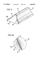
- a trim strip 60 having a substantially V-shaped cross section and formed in accordance with a second embodiment of the present invention will now be described with reference to FIGS. 6-11.
- the strip 60 is formed by first providing a substantially V-shaped polymeric strip 180 of a predetermined length, see FIG. 6.
- FIG. 6 shows the polymeric strip 180 after it has been cut so as to have a straight end 220.
- the strip 180 comprises a first outer layer 180a of first material having an outer surface which defines an upper surface 120 of the polymeric strip 180 and a second core layer 180b of second material which comprises a remainder of the polymeric strip.
- the inner surface of the core layer 180b defines a lower or "hidden" surface 240 of the strip 60.
- an inner third material layer may be provided to define an inner hidden surface 240 with the core layer being interposed between the first and third layers.
- the various layers of the strip 180 may be formed from any of the materials listed above which are used in forming strip 18.
- FIGS. 7 and 10 illustrate the polymeric strip 180 after a cavity 90 has been created by removing material from an end portion of the strip 180.
- a first section (not shown) of the hidden surface is removed leaving a second section 240' remaining.
- the surface of the cavity defines a bonding surface 200 to which injected polymeric material, such as PVC, bonds.
- the cavity may be formed by cutting, grinding or other like processes.
- a heat activated adhesive such as the one described above, is applied to the inner surface of the cavity 90.
- the end portion of the strip 180 is then placed within the inner cavity of a conventional injection mold.
- Polymeric material such as PVC, is injected into the mold to fill the cavity and form an intermediate portion 160, see FIG. 8.
- the intermediate portion 160 has an outer side surface 160a which defines an intermediate surface 60a of the trim strip 60.
- a seam line 100 shown in FIG. 8A, extends between upper and intermediate surfaces 120 and 60a. Because of its location, the seam line 180 is not readily visible from the show surface 120 of the trim strip 60.
- the second end of the polymeric strips 18 and 180 may be subject to the material removal and injection molding defined herein. It is further contemplated by the present invention that any material removal method effective to yield a polymeric strip having an appropriate bonding surface may be employed. Similarly, it is contemplated by the present invention that removal methods resulting in bonding surface profiles different than those shown in FIGS. 4C, 7 and 10 may be employed.
Abstract
Description
Claims (9)
Priority Applications (1)
| Application Number | Priority Date | Filing Date | Title |
|---|---|---|---|
| US08/531,168 US5641547A (en) | 1995-09-13 | 1995-09-13 | Injection molded trim strip and method for making same |
Applications Claiming Priority (1)
| Application Number | Priority Date | Filing Date | Title |
|---|---|---|---|
| US08/531,168 US5641547A (en) | 1995-09-13 | 1995-09-13 | Injection molded trim strip and method for making same |
Publications (1)
| Publication Number | Publication Date |
|---|---|
| US5641547A true US5641547A (en) | 1997-06-24 |
Family
ID=24116533
Family Applications (1)
| Application Number | Title | Priority Date | Filing Date |
|---|---|---|---|
| US08/531,168 Expired - Fee Related US5641547A (en) | 1995-09-13 | 1995-09-13 | Injection molded trim strip and method for making same |
Country Status (1)
| Country | Link |
|---|---|
| US (1) | US5641547A (en) |
Cited By (14)
| Publication number | Priority date | Publication date | Assignee | Title |
|---|---|---|---|---|
| US6279974B1 (en) * | 2000-02-03 | 2001-08-28 | Guardian Automotive Trim, Inc. | Chrome-plated bodyside molding for vehicle and method of making same |
| US6282772B1 (en) | 2000-02-03 | 2001-09-04 | Guardian Automotive Trim, Inc. | Method of making a chrome-plated bodyside molding for a vehicle |
| US6572086B2 (en) | 2001-08-15 | 2003-06-03 | Junior Kelly | External cushion protector for bumper of a parked vehicle |
| US20070013207A1 (en) * | 2003-09-10 | 2007-01-18 | Valeo Systemes D'essuyage | Covering an equipment module whose wall is provided with a rear vision camera |
| US20070141353A1 (en) * | 2003-12-31 | 2007-06-21 | Neitzke Mark K | In Mold Lamination Of Decorative Products |
| US20070137545A1 (en) * | 2005-09-01 | 2007-06-21 | Barbour Corporation | Rub rail with self-contained trim and methods for manufacturing and installing the rub rail |
| US20070194487A1 (en) * | 2003-12-31 | 2007-08-23 | Collins & Aikman Products Co. | In-Mold Lamination Of Decorative Products |
| US20070278830A1 (en) * | 2004-10-01 | 2007-12-06 | Aisin Seiki Kabushiki Kaisha | Mould End Cap |
| US20080290673A1 (en) * | 2007-05-22 | 2008-11-27 | David Arnt | Safety bumper system and method |
| US20090174121A1 (en) * | 2003-12-31 | 2009-07-09 | International Automotive Components Group North America, Inc. | In-Mold Lamination Of Decorative Products |
| US20100075140A1 (en) * | 2003-12-31 | 2010-03-25 | International Automotive Components Group North America, Inc. | In mold lamination of decorative products |
| US20100080970A1 (en) * | 2003-12-31 | 2010-04-01 | International Automotive Components Group North America, Inc. | In mold lamination of decorative products |
| US20100167026A1 (en) * | 2007-01-17 | 2010-07-01 | Hayes Marc A | Decorative products having depth of image |
| US20130078435A1 (en) * | 2011-09-28 | 2013-03-28 | Joseph A. Massetti | Method for multi-color vehicle interior components and components formed from the method |
Citations (8)
| Publication number | Priority date | Publication date | Assignee | Title |
|---|---|---|---|---|
| JPS61132315A (en) * | 1984-11-30 | 1986-06-19 | Hashimoto Forming Co Ltd | Manufacture of molding for vehicle |
| US4617209A (en) * | 1985-01-08 | 1986-10-14 | Lof Plastics Inc. | Molded end cap for extruded trims |
| US4619847A (en) * | 1984-03-20 | 1986-10-28 | The Standard Products Company | Trim strip having injection molded finishing portion and method of making |
| US4719067A (en) * | 1984-06-05 | 1988-01-12 | Gebr. Happich Gmbh | Method and apparatus for forming end pieces on plastic molding strips |
| US5069849A (en) * | 1990-02-07 | 1991-12-03 | Wain Peter L | Method for forming a molding |
| US5227108A (en) * | 1991-12-12 | 1993-07-13 | The Standard Products Company | Method of forming decorative trim strips |
| US5350608A (en) * | 1993-04-13 | 1994-09-27 | The Standard Products Company | Decorative trim with one-piece plastic cover |
| US5419863A (en) * | 1992-03-06 | 1995-05-30 | The Standard Products Company | Method of making a seamless backfilled molding |
-
1995
- 1995-09-13 US US08/531,168 patent/US5641547A/en not_active Expired - Fee Related
Patent Citations (8)
| Publication number | Priority date | Publication date | Assignee | Title |
|---|---|---|---|---|
| US4619847A (en) * | 1984-03-20 | 1986-10-28 | The Standard Products Company | Trim strip having injection molded finishing portion and method of making |
| US4719067A (en) * | 1984-06-05 | 1988-01-12 | Gebr. Happich Gmbh | Method and apparatus for forming end pieces on plastic molding strips |
| JPS61132315A (en) * | 1984-11-30 | 1986-06-19 | Hashimoto Forming Co Ltd | Manufacture of molding for vehicle |
| US4617209A (en) * | 1985-01-08 | 1986-10-14 | Lof Plastics Inc. | Molded end cap for extruded trims |
| US5069849A (en) * | 1990-02-07 | 1991-12-03 | Wain Peter L | Method for forming a molding |
| US5227108A (en) * | 1991-12-12 | 1993-07-13 | The Standard Products Company | Method of forming decorative trim strips |
| US5419863A (en) * | 1992-03-06 | 1995-05-30 | The Standard Products Company | Method of making a seamless backfilled molding |
| US5350608A (en) * | 1993-04-13 | 1994-09-27 | The Standard Products Company | Decorative trim with one-piece plastic cover |
Cited By (26)
| Publication number | Priority date | Publication date | Assignee | Title |
|---|---|---|---|---|
| US6282772B1 (en) | 2000-02-03 | 2001-09-04 | Guardian Automotive Trim, Inc. | Method of making a chrome-plated bodyside molding for a vehicle |
| US6372311B2 (en) | 2000-02-03 | 2002-04-16 | Guardian Industries Corp. | Chrome-plated bodyside molding for vehicle and method of making same |
| US6279974B1 (en) * | 2000-02-03 | 2001-08-28 | Guardian Automotive Trim, Inc. | Chrome-plated bodyside molding for vehicle and method of making same |
| US6572086B2 (en) | 2001-08-15 | 2003-06-03 | Junior Kelly | External cushion protector for bumper of a parked vehicle |
| US7380851B2 (en) * | 2003-09-10 | 2008-06-03 | Valeo Systemes D'essuyage | Covering an equipment module whose wall is provided with a rear vision camera |
| US20070013207A1 (en) * | 2003-09-10 | 2007-01-18 | Valeo Systemes D'essuyage | Covering an equipment module whose wall is provided with a rear vision camera |
| US20100154986A1 (en) * | 2003-12-31 | 2010-06-24 | International Automotive Components Group North America, Inc. | In Mold Lamination Of Decorative Products |
| US20100080970A1 (en) * | 2003-12-31 | 2010-04-01 | International Automotive Components Group North America, Inc. | In mold lamination of decorative products |
| US7981342B2 (en) | 2003-12-31 | 2011-07-19 | International Automotive Components Group North America, Inc. | In-mold lamination of decorative products |
| US20070194487A1 (en) * | 2003-12-31 | 2007-08-23 | Collins & Aikman Products Co. | In-Mold Lamination Of Decorative Products |
| US8071000B2 (en) | 2003-12-31 | 2011-12-06 | International Automotive Components Group North America, Inc. | In mold lamination of decorative products |
| US8092733B2 (en) | 2003-12-31 | 2012-01-10 | International Automotive Components Group North America, Inc. | In mold lamination of decorative products |
| US20090174121A1 (en) * | 2003-12-31 | 2009-07-09 | International Automotive Components Group North America, Inc. | In-Mold Lamination Of Decorative Products |
| US8083979B2 (en) | 2003-12-31 | 2011-12-27 | International Automotive Components Group North America, Inc. | In mold lamination of decorative products |
| US7674414B2 (en) | 2003-12-31 | 2010-03-09 | International Automotive Components Group North America, Inc. | In mold lamination of decorative products |
| US20100075140A1 (en) * | 2003-12-31 | 2010-03-25 | International Automotive Components Group North America, Inc. | In mold lamination of decorative products |
| US20070141353A1 (en) * | 2003-12-31 | 2007-06-21 | Neitzke Mark K | In Mold Lamination Of Decorative Products |
| US7407205B2 (en) * | 2004-10-01 | 2008-08-05 | Aisin Seiki Kabushiki Kaisha | Mould end cap |
| US20070278830A1 (en) * | 2004-10-01 | 2007-12-06 | Aisin Seiki Kabushiki Kaisha | Mould End Cap |
| US7685956B2 (en) * | 2005-09-01 | 2010-03-30 | Barbour Plastics, Inc. | Rub rail with self-contained trim and methods for manufacturing and installing the rub rail |
| US20070137545A1 (en) * | 2005-09-01 | 2007-06-21 | Barbour Corporation | Rub rail with self-contained trim and methods for manufacturing and installing the rub rail |
| US20100167026A1 (en) * | 2007-01-17 | 2010-07-01 | Hayes Marc A | Decorative products having depth of image |
| US7611176B2 (en) * | 2007-05-22 | 2009-11-03 | David Arnt | Safety bumper system and method |
| US20080290673A1 (en) * | 2007-05-22 | 2008-11-27 | David Arnt | Safety bumper system and method |
| US20130078435A1 (en) * | 2011-09-28 | 2013-03-28 | Joseph A. Massetti | Method for multi-color vehicle interior components and components formed from the method |
| US10730263B2 (en) * | 2011-09-28 | 2020-08-04 | Inteva Products, Llc | Method for multi-color vehicle interior components and components formed from the method |
Similar Documents
| Publication | Publication Date | Title |
|---|---|---|
| US5641547A (en) | Injection molded trim strip and method for making same | |
| CA2089978C (en) | Automotive trim piece | |
| US4619847A (en) | Trim strip having injection molded finishing portion and method of making | |
| US4277526A (en) | Protective and decorative molding having foam-filled channel | |
| US5091031A (en) | Method for forming plastic molded panels with inserts | |
| CA2056291C (en) | Invisible air bag cover door | |
| US5552195A (en) | Trim strip and method for making same | |
| US6168742B1 (en) | Method of insert molding auto and truck bumper, rocker panel and chin spoiler parts | |
| US20210102423A1 (en) | Composite glass pane with a border seal and method for producing same | |
| US4515649A (en) | Thermoplastic elastomer molding | |
| GB2080193A (en) | Thermoplastic elastomer moulding | |
| US5252164A (en) | Method for making a supplemental impact restraint door and instrument panel system from single, unitary cover | |
| US4368225A (en) | Molding laminate | |
| US5350608A (en) | Decorative trim with one-piece plastic cover | |
| US4978490A (en) | Full overlaying injection molding | |
| US5139830A (en) | Decorative molding | |
| GB2078620A (en) | Protective trim strip | |
| US20100263292A1 (en) | Multi-material layered extrusion | |
| US5772827A (en) | Trim member including intermittent bright strip and method of making same | |
| US4497678A (en) | Method of making a laminate construction | |
| US20080315621A1 (en) | Trim Panel for the Interior of a Motor Vehicle and a Manufacturing Process for Such a Trim Panel | |
| JP2596096B2 (en) | Window molding and manufacturing method thereof | |
| CN1781693A (en) | Method of producing a composite component and deep-drawing mold for same | |
| JP6632094B2 (en) | Automotive interior parts | |
| JPH05229367A (en) | Instrument panel and its manufacture |
Legal Events
| Date | Code | Title | Description |
|---|---|---|---|
| AS | Assignment |
Owner name: PLASTIC TRIM, INC., OHIO Free format text: ASSIGNMENT OF ASSIGNORS INTEREST;ASSIGNOR:DILLEY, DAVID DWIGHT;REEL/FRAME:007720/0985 Effective date: 19951103 |
|
| CC | Certificate of correction | ||
| FPAY | Fee payment |
Year of fee payment: 4 |
|
| FPAY | Fee payment |
Year of fee payment: 8 |
|
| AS | Assignment |
Owner name: PTI ACQUISITION, LLC, OHIO Free format text: ASSIGNMENT OF ASSIGNORS INTEREST;ASSIGNORS:JPE, INC.;PLASTIC TRIM, INC.;REEL/FRAME:019440/0477 Effective date: 20030613 |
|
| REMI | Maintenance fee reminder mailed | ||
| LAPS | Lapse for failure to pay maintenance fees | ||
| STCH | Information on status: patent discontinuation |
Free format text: PATENT EXPIRED DUE TO NONPAYMENT OF MAINTENANCE FEES UNDER 37 CFR 1.362 |
|
| FP | Lapsed due to failure to pay maintenance fee |
Effective date: 20090624 |