US5644173A - Real time and/shed load based on received tier pricing and direct load control with processors for each load - Google Patents
Real time and/shed load based on received tier pricing and direct load control with processors for each load Download PDFInfo
- Publication number
- US5644173A US5644173A US08/329,731 US32973194A US5644173A US 5644173 A US5644173 A US 5644173A US 32973194 A US32973194 A US 32973194A US 5644173 A US5644173 A US 5644173A
- Authority
- US
- United States
- Prior art keywords
- load
- processor
- value
- tier
- signal
- Prior art date
- Legal status (The legal status is an assumption and is not a legal conclusion. Google has not performed a legal analysis and makes no representation as to the accuracy of the status listed.)
- Expired - Lifetime
Links
Images


Classifications
-
- H—ELECTRICITY
- H02—GENERATION; CONVERSION OR DISTRIBUTION OF ELECTRIC POWER
- H02J—CIRCUIT ARRANGEMENTS OR SYSTEMS FOR SUPPLYING OR DISTRIBUTING ELECTRIC POWER; SYSTEMS FOR STORING ELECTRIC ENERGY
- H02J3/00—Circuit arrangements for ac mains or ac distribution networks
- H02J3/12—Circuit arrangements for ac mains or ac distribution networks for adjusting voltage in ac networks by changing a characteristic of the network load
- H02J3/14—Circuit arrangements for ac mains or ac distribution networks for adjusting voltage in ac networks by changing a characteristic of the network load by switching loads on to, or off from, network, e.g. progressively balanced loading
-
- H—ELECTRICITY
- H02—GENERATION; CONVERSION OR DISTRIBUTION OF ELECTRIC POWER
- H02J—CIRCUIT ARRANGEMENTS OR SYSTEMS FOR SUPPLYING OR DISTRIBUTING ELECTRIC POWER; SYSTEMS FOR STORING ELECTRIC ENERGY
- H02J2310/00—The network for supplying or distributing electric power characterised by its spatial reach or by the load
- H02J2310/50—The network for supplying or distributing electric power characterised by its spatial reach or by the load for selectively controlling the operation of the loads
- H02J2310/56—The network for supplying or distributing electric power characterised by its spatial reach or by the load for selectively controlling the operation of the loads characterised by the condition upon which the selective controlling is based
- H02J2310/62—The condition being non-electrical, e.g. temperature
- H02J2310/64—The condition being economic, e.g. tariff based load management
-
- Y—GENERAL TAGGING OF NEW TECHNOLOGICAL DEVELOPMENTS; GENERAL TAGGING OF CROSS-SECTIONAL TECHNOLOGIES SPANNING OVER SEVERAL SECTIONS OF THE IPC; TECHNICAL SUBJECTS COVERED BY FORMER USPC CROSS-REFERENCE ART COLLECTIONS [XRACs] AND DIGESTS
- Y02—TECHNOLOGIES OR APPLICATIONS FOR MITIGATION OR ADAPTATION AGAINST CLIMATE CHANGE
- Y02B—CLIMATE CHANGE MITIGATION TECHNOLOGIES RELATED TO BUILDINGS, e.g. HOUSING, HOUSE APPLIANCES OR RELATED END-USER APPLICATIONS
- Y02B70/00—Technologies for an efficient end-user side electric power management and consumption
- Y02B70/30—Systems integrating technologies related to power network operation and communication or information technologies for improving the carbon footprint of the management of residential or tertiary loads, i.e. smart grids as climate change mitigation technology in the buildings sector, including also the last stages of power distribution and the control, monitoring or operating management systems at local level
- Y02B70/3225—Demand response systems, e.g. load shedding, peak shaving
-
- Y—GENERAL TAGGING OF NEW TECHNOLOGICAL DEVELOPMENTS; GENERAL TAGGING OF CROSS-SECTIONAL TECHNOLOGIES SPANNING OVER SEVERAL SECTIONS OF THE IPC; TECHNICAL SUBJECTS COVERED BY FORMER USPC CROSS-REFERENCE ART COLLECTIONS [XRACs] AND DIGESTS
- Y04—INFORMATION OR COMMUNICATION TECHNOLOGIES HAVING AN IMPACT ON OTHER TECHNOLOGY AREAS
- Y04S—SYSTEMS INTEGRATING TECHNOLOGIES RELATED TO POWER NETWORK OPERATION, COMMUNICATION OR INFORMATION TECHNOLOGIES FOR IMPROVING THE ELECTRICAL POWER GENERATION, TRANSMISSION, DISTRIBUTION, MANAGEMENT OR USAGE, i.e. SMART GRIDS
- Y04S20/00—Management or operation of end-user stationary applications or the last stages of power distribution; Controlling, monitoring or operating thereof
- Y04S20/20—End-user application control systems
- Y04S20/222—Demand response systems, e.g. load shedding, peak shaving
-
- Y—GENERAL TAGGING OF NEW TECHNOLOGICAL DEVELOPMENTS; GENERAL TAGGING OF CROSS-SECTIONAL TECHNOLOGIES SPANNING OVER SEVERAL SECTIONS OF THE IPC; TECHNICAL SUBJECTS COVERED BY FORMER USPC CROSS-REFERENCE ART COLLECTIONS [XRACs] AND DIGESTS
- Y04—INFORMATION OR COMMUNICATION TECHNOLOGIES HAVING AN IMPACT ON OTHER TECHNOLOGY AREAS
- Y04S—SYSTEMS INTEGRATING TECHNOLOGIES RELATED TO POWER NETWORK OPERATION, COMMUNICATION OR INFORMATION TECHNOLOGIES FOR IMPROVING THE ELECTRICAL POWER GENERATION, TRANSMISSION, DISTRIBUTION, MANAGEMENT OR USAGE, i.e. SMART GRIDS
- Y04S50/00—Market activities related to the operation of systems integrating technologies related to power network operation or related to communication or information technologies
- Y04S50/10—Energy trading, including energy flowing from end-user application to grid
Definitions
- This invention relates to reducing energy costs (in conjunction with time-of-use pricing with rates that vary according to energy costs) and has particular application to home control and building control in general and is useful in areas supplied by electric utilities that wish to engage in demand side management of their area. It is particularly addressed to add/shed load control in the control of facilities that have individual processors for subsystems to which add/shed load control may be applied. It also allows for direct load control (DLC) by the utility provider in a cooperative system.
- DLC direct load control
- the invention herein provides a way to adapt users of electricity to reduce their demand through an add/shed strategy which can be applied in real time and in cooperation with consumer needs.
- the control system can reduce the energy consumption within the premise during times when the cost of energy is high.
- the utility in turn can reduce the necessary generating capacity for a given area.
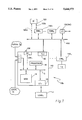
- FIG. 1 is a conceptual block diagram of one form of the preferred embodiment of the invention.
- FIG. 1A is a conceptual block diagram of a preferred embodiment bus structure for the invention.
- FIG. 2 is a conceptual block diagram of the power supplier's or company's interface to a controller in one preferred embodiment of the invention.
- FIG. 3 is a two-dimensional overview diagram of a house which may be employed having a number of systems controllable in accord with one of the preferred embodiments of the invention.
- FIG. 4a is a model of the display used by one embodiment of this invention.
- FIGS. 4b-r are ordered sets of displays in accord with one embodiment of this invention available to the user through the display illustrated in FIG. 4a.
- FIG. 5 is a flow diagram illustrating how a preferred embodiment uses the add/shed strategy to adjust to incoming signals.
- a controller for controlling the energy-consuming equipment and systems in a building which may benefit from changing utility rate information is taught in this invention.
- the controller sends price tier information to the individual controllers for the add/shed loads (also called subsystems).
- add/shed loads also called subsystems.
- Each of these contain information indicating the appropriate action that the load should take based on whether there is a user override and whether there is direct utility control as well as on tier information.
- the controller in the building will have a gateway for communicating the tier and DLC signals to the controller from the utility.
- a significant amount of variability is available to the designer employing the invention described herein, which should only be considered limited by the claims.
- FIG. 1 describes the control system 100 including a controller 110, the system 100 having in the preferred embodiment a user interface 120 (which may be connected to the power line through another controller 120c via lines 120b or directly through 120a).
- the controller 110 preferably includes memory subsystem 14, load control interface 15 and power line interface 40; each of which communicate with a processor 16, either through direct connections or via a controller bus like bus 5.
- a communications interface to the utility called an External Interface
- EI 130 is connected to the controller through power line interface 400.
- the controller 110 may send output signals to load L 1 , and the user interface 120 as desired by the user for controlling the load that is controlled by the controller 110.
- Many such controllers 110 to 110 n may be included on the power line 400 and each operates to add/shed its load(s) independently.
- the controller 110 may be enhanced and have the benefit of local information for making its decision regarding adding/shedding loads or other tasks it might be assigned.
- this is illustrated by having a local temperature sensor Ts and a local current sensor Is provide signal input to a current and temperature interface TII which, in turn, can communicate these signals in an intelligible manner to the processor 16 via bus 5.
- a preferred bus structure for setting up the interfaces between the controller and the other components is described with reference to FIG. 1A.
- This bus would allow for communications of data and control signals between the various components that may be attached to bus 81 (here, for example, actuator 18 and H-Bus interface 91.
- the H-BusTM system for example, provides for a DC balanced, limited set of code words which all systems may read and which only appropriate systems will react to.
- Alternative busses are well known and, as the art develops, new busses will become known and the most efficient bus for the appropriate situation should be employed by the designer.
- H-BusTM interface 91 merely provides for communications between two busses, 81 and 82, where bus 82 may be, alternatively, another H-BusTM, or perhaps even a power line used as a bus.
- bus 82 side of interface 91 will, of course, have to be adapted to the particular situation. In this situation, for example, controller 17 could connect directly to bus 82 if it were an H-BusTM, and interface 91 would not be needed.
- the external interface 86 to the utility 85 in the preferred embodiment interfaces with a utility provided coaxial cable 84 although there are many ways the utility pricing signal could be fed into the system 8 (for example, RFI 86a could receive RF signals). Likewise, fiber-optic cable or the power lines themselves may be used if desired.
- this communication can be two-way, to also provide data back to the utility.
- the utility may use such a system to determine which customers have active overrides of DLC signals, for example.
- the controller 87 (11) resides on both a serial bus 82 and on the power line which here is also used for communicating data.
- the user interface 12 preferably also resides on the same serial bus 82.
- a power line interface (PLI) (which may also be provided to all communicating systems on the power line) will, in the minimum configuration for using a power line interface, provide signals from the controller through the power line 83 to systems that function through power line controllers (for example, LSM controller module 88 which controls load 89).
- a light (which might be load 89) could be turned on or off at various times of the day or according to various other factors taken into consideration by the controller 88.
- a light (which might be load 89) could be turned on or off at various times of the day or according to various other factors taken into consideration by the controller 88.
- Many other configurations based on this example should be readily apparent to those of ordinary skill in this art.
- a telephone line 25 may connect an interface 13a to the controller in a house or in a building, for instance, or a direct line 21 may go directly to the interface box 13d which connects to the controller 11. If the power company opts to send signals through the power lines 24 themselves to interface box 13b, a number of problems may develop with the carrying of such signals through the transformer network currently employed by electric utility companies, for example.
- the utility signals the user's facility/home/building via a coaxial cable. This signal is transferred into the facility's internal power lines, where a power line interface receives the signals.
- FIG. 3 has a collapsed floor plan of a house 30 and pool 40 showing various subsystems 31-39 and 41, which are controllable through the use of this invention.
- the air conditioning subsystem 31 and the furnace or heating subsystem (preferably electric) 34 generally will work together through a thermostat (not shown).
- a vertical-blind-turning motor or curtain-moving motor 32 could be provided to reduce heat load or increase heat load provided by the sun on rooms in a building through a window.
- this invention is preferably applied to, for example, various lighting subsystems which may be controlled individually such as plant lights 33 in an arboretum, exterior security lights 38a and 38c and exterior pool lights 39a-c.
- a hot water heater 35, washer/dryer 36, refrigerator 37 and pool pump 41 provide other examples of subsystems which may also be controlled by use of this invention if desired.
- controller interfaces such as 13a, 15d, 13b and 16 may be employed for controlling these subsystems of the user's homes.
- the security light system 38a and 38b may be turned on at all times during the evening hours, regardless of cost, in a high-crime neighborhood.
- the pool pump subsystem 41 and outdoor pool lights 39a-c would likely be turned off (shed) any time price of power for them reaches a certain tier.
- an owner/occupier of a building space would prefer to override a standard program and this can be included as well.
- thermostats have become well distributed within the United States and are well known elsewhere. These thermostats allow for programming by the occupant to accommodate his schedule. The simplest version would have two modes or periods, a high and a low, but most have at least four.
- WAKE, LEAVE, RETURN and SLEEP which may roughly be interpreted as warm up the house in the winter because the occupant is waking, the occupant is leaving so reduce power consumption for maintaining the comfort in a space, the occupant is returning and wants a higher level of comfort, and the occupant expects to be asleep and therefore a different temperature and comfort level is required.
- An exemplary unit is produced by Honeywell Inc. and goes by the trademark "MagicstatTM", and provides these four modes for the occupant to program.
- HVAC heating, ventilation and air conditioning
- FIG. 5 describes how the signals provided by the utility company are incorporated into the preferred embodiment system 60.
- the first load (or the next in line in the sequence or all at once if organized in parallel) gets set to an ENABLED condition and the Override condition gets set to FALSE.
- This process 61 may be accomplished on a processor that is in controller 110 in FIG. 1 or by a centralized processor which could be, for example, associated with the user interface 90 of FIG. 1A.
- all the processes 61-69b are performed on a processor like processor 16 of controller 110 and the enabled and override conditions are set centrally by setting a network variable.
- process 62 is a process which checks the value assigned to the network variable (i.e., that collection of data signals that is stored in memory for the control system network which represents a particular load or is used by all the load controllers) and, after determining its value, assigning the processor's next process call to either process 63 if the value is "ON” (or enabled) or to process 66 if the value is "OFF” (or disabled).
- the network variable i.e., that collection of data signals that is stored in memory for the control system network which represents a particular load or is used by all the load controllers
- NeuronsTM An exemplary platform for interprocessor communication, handling network variables and other tasks is provided under the tradename “LONWORKSTM” by Echelon Corporation of California. Their processor units, called NeuronsTM could also perform the processes described for the load controller herein described.
- process 63 checks for whether there is an active direct load control (or DLC) signal from the utility.
- a DLC signal is an indication by the utility that it needs to exercise direct control ("Direct Load Control") over electricity usage. If this signal (again, most effectively maintained as a network variable after it's initiation into the system through a utility gateway such as EI 13 of FIG. 1) is INACTIVE, in the preferred embodiment, then process 69 checks to see if the signal specifies or indicates a higher tier than the load under consideration and if it does, process 69 signals over 69a to indicate that the load should be shed or turned off process. Otherwise this signal goes via route 69b to initiate process 68 to turn the load on or keep it on. However, before turning off the load, route 69a is taken leading through process 65b.
- Process 65b checks to see first if there is a pending override request (preferably by checking a network variable) and then checks to see if overrides are allowed (on this load or at all, depending on how the user configures his system in cooperation with the utility). If, and only if both questions are answered affirmatively, then process 68 is activated. Otherwise process 66 is activated, turning the load off.
- the process 64 checks the duty cycle for its load. If the duty cycle currently equals one than the load is turned on, and if the duty cycle equals zero than the load is turned off, by definition, that means the load is off (even though it's enabled) and the next process is either to turn the load off or simply restart a timer process 67.
- process 65a checks for override requests and whether they are allowed as did process 65b. Based on the same criteria, it may activate process 66 or process 68. (If so desired, for loads to which the concepts of duty cycle is irrelevant, process 64 may be eliminated but it is preferred here since it is accomplished with a convenient programming step.
- duty cycle time for responding to recently supplied tier information signals may be done instead, or even setpoint offsets might be used in appropriate circumstances.
- step 69 this alternative is chosen [ALT]
- the processor would access a user-defined table of tier values corresponding to duty cycle percentages and the processor would then cause the duty cycle to change to correspond to the tier value sent.
- the user could then select to override such a charge through a process like 65B.
- any value laden signal could be called a "tier" signal. So, for example, if the utility provider sent signals corresponding to real time price data, the processor would have to be modified to respond to such data rather than to a "tier" level signal. It is presently felt that the simplicity provided by using a limited number of tier signals affords use of simpler processors and for that reason it is presently preferred. The practitioner of ordinary skill can easily adapt this invention to any type of consistent signaling mechanism.
- an override request is something decided between the utility and the user. This is an accommodation to the needs of both. For example, if the user cannot afford to have the lights turned off in a part of his plant, say, during a growth cycle for some bacteria he is growing, he can negotiate with the utility provider to either put that room, via its controller, into the highest tier, which will cost something the utility and user agree to. Alternatively, the user could maintain an override, or exclude DLC from the particular subsystem altogether. If the price is too steep for the value, the consumer/customer may agree to put his lights on a cycle timer 67 that only kicks in at the highest price (for example).
- the appropriate adjustment would be to allow for the utility to control the pool light load through a DLC signal, but if the rates merely climb, to allow for a user override that stops the process from shutting down these lights at times when the rates are high. This is the level of control available through the addition of processes 65a and 65b to the preferred embodiment wherein the user may negotiate whether overrides of DLC are allowed.
- a user interface panel 50 contains a display area 51, a set of four soft keys 52a, b, c, d, and two hard keys 53, Select and Back.
- arrows or other symbols 55 indicate the functions of the soft keys 52a-d by reference 56 associated with each such symbol 55.
- a display merely indicates information about the user's options, such as a help screen
- a display configuration such as that shown in FIG. 4c may be provided in the preferred embodiments.
- information 57 and a zone name or message 54 is preferably provided on the display 51 as in FIG. 4a.
- keys 52 and 53 contain information regarding their function which would not generally be available to the user.
- key 52a has two "+” signs indicating that the function of softkey 52a is to increase the amount of warmth
- key 52b has two "-” signs to show that the amount of warmth should be decreased and that the setpoint should be reduced.
- "++" and "--" keys will not be on the user touch pad but are included in these drawings to provide redundant information to the reader in order to facilitate the grasp of the inventive concepts of this document).
- softkeys allows the user to control it without requiring a complicated or expensive user interface such as a general-purpose computer.
- general purpose computers or other interface devices may be used if desired.
- the utility may provide for the actuation of particular profiles within individual spaces or homes directly, but this would require such a utility to maintain an active database and provide a method by which the users could modify that database to their own desires on some kind of acceptable basis.
- N/A would indicate that that particular key cannot perform any function with this particular display.
- N/S indicates a feature not shown or described.
- FIGS. 4a-r provide a generalized set of displays for interfacing to a control system, other options are available.
- the utility may, if preferred, simply agree to install a hard-configured controller that, for example, does not allow for overrides or that controls through overrides through process 65b.
- a hard-configured controller that, for example, does not allow for overrides or that controls through overrides through process 65b.
Abstract
Description
Claims (11)
Priority Applications (1)
| Application Number | Priority Date | Filing Date | Title |
|---|---|---|---|
| US08/329,731 US5644173A (en) | 1994-10-25 | 1994-10-25 | Real time and/shed load based on received tier pricing and direct load control with processors for each load |
Applications Claiming Priority (1)
| Application Number | Priority Date | Filing Date | Title |
|---|---|---|---|
| US08/329,731 US5644173A (en) | 1994-10-25 | 1994-10-25 | Real time and/shed load based on received tier pricing and direct load control with processors for each load |
Publications (1)
| Publication Number | Publication Date |
|---|---|
| US5644173A true US5644173A (en) | 1997-07-01 |
Family
ID=23286761
Family Applications (1)
| Application Number | Title | Priority Date | Filing Date |
|---|---|---|---|
| US08/329,731 Expired - Lifetime US5644173A (en) | 1994-10-25 | 1994-10-25 | Real time and/shed load based on received tier pricing and direct load control with processors for each load |
Country Status (1)
| Country | Link |
|---|---|
| US (1) | US5644173A (en) |
Cited By (94)
| Publication number | Priority date | Publication date | Assignee | Title |
|---|---|---|---|---|
| US6181985B1 (en) | 1998-04-29 | 2001-01-30 | The Detroit Edison Company | Rate-based load shed module |
| US6429785B1 (en) | 1999-01-08 | 2002-08-06 | Siemens Power Transmission & Distribution Inc. | Revenue meter having precision time clock |
| US20020130558A1 (en) * | 2001-03-14 | 2002-09-19 | Wattenburg Willard H. | Method and system to automatically reduce generated power |
| US6480803B1 (en) | 2000-12-22 | 2002-11-12 | Carrier Corporation | Load shedding thermostat |
| US20030036820A1 (en) * | 2001-08-16 | 2003-02-20 | International Business Machines Corporation | Method for optimizing energy consumption and cost |
| US20040107339A1 (en) * | 2002-11-29 | 2004-06-03 | Kabushiki Kaisha Toshiba | Electronic apparatus and method of setting system environment of the electronic apparatus |
| US20040240132A1 (en) * | 2003-05-30 | 2004-12-02 | Hudson Christopher A. | Hid dimming system interface box |
| US20050065742A1 (en) * | 2003-09-08 | 2005-03-24 | Smartsynch, Inc. | Systems and methods for remote power management using IEEE 802 based wireless communication links |
| US7062361B1 (en) | 2000-05-02 | 2006-06-13 | Mark E. Lane | Method and apparatus for controlling power consumption |
| US20060124759A1 (en) * | 2004-12-14 | 2006-06-15 | Rossi John F | HVAC communication system |
| US20060184288A1 (en) * | 2003-09-08 | 2006-08-17 | Smartsynch, Incorporated | Systems and methods for remote power management using 802.11 wireless protocols |
| US20070129851A1 (en) * | 2005-09-07 | 2007-06-07 | Rossi John F | Method and System for Local Load Control |
| US20070129850A1 (en) * | 2005-09-07 | 2007-06-07 | Miyaji Wendell M | Local Power Consumption Load Control |
| US20080135465A1 (en) * | 2006-12-08 | 2008-06-12 | Shawn Davis | Energy saving system for use with swimming pool filter systems |
| US20080183337A1 (en) * | 2007-01-31 | 2008-07-31 | Fifth Light Technology Ltd. | Methods and systems for controlling addressable lighting units |
| US20080275802A1 (en) * | 2007-05-03 | 2008-11-06 | Verfuerth Neal R | System and method for a utility financial model |
| US20090143916A1 (en) * | 2007-11-30 | 2009-06-04 | Honeywell International, Inc. | Hvac controller having a parameter adjustment element with a qualitative indicator |
| US20090216382A1 (en) * | 2008-02-26 | 2009-08-27 | Howard Ng | Direct Load Control System and Method with Comfort Temperature Setting |
| US20090248217A1 (en) * | 2008-03-27 | 2009-10-01 | Orion Energy Systems, Inc. | System and method for reducing peak and off-peak electricity demand by monitoring, controlling and metering high intensity fluorescent lighting in a facility |
| US20090243517A1 (en) * | 2008-03-27 | 2009-10-01 | Orion Energy Systems, Inc. | System and method for controlling lighting |
| US20100061088A1 (en) * | 2007-06-29 | 2010-03-11 | Orion Energy Systems, Inc. | Lighting device |
| US20100114799A1 (en) * | 2008-10-31 | 2010-05-06 | General Electric Company | Optimal dispatch of demand side electricity resources |
| US20100145544A1 (en) * | 2007-08-28 | 2010-06-10 | Forbes Jr Joseph W | System and method for selective disconnection of electrical service to end customers |
| US20100161148A1 (en) * | 2007-08-28 | 2010-06-24 | Forbes Jr Joseph W | Method and apparatus for actively managing consumption of electric power supplied by an electric utility |
| US20110022239A1 (en) * | 2007-08-28 | 2011-01-27 | Forbes Jr Joseph W | Method and apparatus for effecting controlled restart of electrical servcie with a utility service area |
| US20110060701A1 (en) * | 2009-09-04 | 2011-03-10 | Orion Energy Systems, Inc. | Outdoor fluorescent lighting fixtures and related systems and methods |
| US20110066037A1 (en) * | 2009-09-14 | 2011-03-17 | Matt Banet | Body-worn monitor for measuring respiration rate |
| US20110172841A1 (en) * | 2007-08-28 | 2011-07-14 | Forbes Jr Joseph W | Method and Apparatus for Actively Managing Consumption of Electric Power Supplied by One or More Electric Utilities |
| US20110172837A1 (en) * | 2007-08-28 | 2011-07-14 | Forbes Jr Joseph W | System and method for estimating and providing dispatchable operating reserve energy capacity through use of active load management |
| US20110184565A1 (en) * | 2010-01-22 | 2011-07-28 | Honeywell International Inc. | Hvac control with utility time of day pricing support |
| US20110184564A1 (en) * | 2010-01-22 | 2011-07-28 | Honeywell International Inc. | Hvac control with utility time of day pricing support |
| US20110184562A1 (en) * | 2010-01-22 | 2011-07-28 | Honeywell International Inc. | Hvac control with utility time of day pricing support |
| US20110213332A1 (en) * | 2010-03-01 | 2011-09-01 | Koorosh Mozayeny | Medication delivery system |
| US20110213510A1 (en) * | 2010-03-01 | 2011-09-01 | Koorosh Mozayeny | Smart power strip |
| US20110209765A1 (en) * | 2010-03-01 | 2011-09-01 | Koorosh Mozayeny | Water flow regulation system |
| US20110238224A1 (en) * | 2010-03-24 | 2011-09-29 | Honeywell International Inc. | Setpoint recovery with utility time of day pricing |
| US20110298286A1 (en) * | 2010-06-03 | 2011-12-08 | Briggs & Stratton Corporation | Dynamic load shedding system for a standby generator |
| US20120101651A1 (en) * | 2007-12-19 | 2012-04-26 | David Haynes | Achieving energy demand response using price signals and a load control transponder |
| JP2012130088A (en) * | 2010-12-13 | 2012-07-05 | Panasonic Corp | Apparatus controller and apparatus control method |
| US20120209445A1 (en) * | 2009-10-26 | 2012-08-16 | Yanghwan Kim | Method of controlling network system |
| US20120215370A1 (en) * | 2009-10-26 | 2012-08-23 | Lg Electronics Inc. | Network system and method of controlling the same |
| JP2012178915A (en) * | 2011-02-25 | 2012-09-13 | Panasonic Corp | Apparatus controller, apparatus control method, and apparatus control program |
| US20120245744A1 (en) * | 2011-03-25 | 2012-09-27 | Green Charge Networks Llc | Networked Power Management and Demand Response |
| US8396606B2 (en) | 2007-08-28 | 2013-03-12 | Consert Inc. | System and method for estimating and providing dispatchable operating reserve energy capacity through use of active load management |
| US8445826B2 (en) | 2007-06-29 | 2013-05-21 | Orion Energy Systems, Inc. | Outdoor lighting systems and methods for wireless network communications |
| US8450670B2 (en) | 2007-06-29 | 2013-05-28 | Orion Energy Systems, Inc. | Lighting fixture control systems and methods |
| US8478447B2 (en) | 2010-11-19 | 2013-07-02 | Nest Labs, Inc. | Computational load distribution in a climate control system having plural sensing microsystems |
| US8476565B2 (en) | 2007-06-29 | 2013-07-02 | Orion Energy Systems, Inc. | Outdoor lighting fixtures control systems and methods |
| US8586902B2 (en) | 2007-06-29 | 2013-11-19 | Orion Energy Systems, Inc. | Outdoor lighting fixture and camera systems |
| US8620841B1 (en) | 2012-08-31 | 2013-12-31 | Nest Labs, Inc. | Dynamic distributed-sensor thermostat network for forecasting external events |
| US8620460B2 (en) | 2003-12-01 | 2013-12-31 | Honeywell International Inc. | Controller interface with multiple day programming |
| US8627127B2 (en) | 2011-02-24 | 2014-01-07 | Nest Labs, Inc. | Power-preserving communications architecture with long-polling persistent cloud channel for wireless network-connected thermostat |
| US8630741B1 (en) | 2012-09-30 | 2014-01-14 | Nest Labs, Inc. | Automated presence detection and presence-related control within an intelligent controller |
| US8695888B2 (en) | 2004-10-06 | 2014-04-15 | Nest Labs, Inc. | Electronically-controlled register vent for zone heating and cooling |
| US8729446B2 (en) | 2007-06-29 | 2014-05-20 | Orion Energy Systems, Inc. | Outdoor lighting fixtures for controlling traffic lights |
| US8806239B2 (en) | 2007-08-28 | 2014-08-12 | Causam Energy, Inc. | System, method, and apparatus for actively managing consumption of electric power supplied by one or more electric power grid operators |
| US8805552B2 (en) | 2007-08-28 | 2014-08-12 | Causam Energy, Inc. | Method and apparatus for actively managing consumption of electric power over an electric power grid |
| US8849715B2 (en) | 2012-10-24 | 2014-09-30 | Causam Energy, Inc. | System, method, and apparatus for settlement for participation in an electric power grid |
| US8855279B2 (en) | 2007-08-28 | 2014-10-07 | Consert Inc. | Apparatus and method for controlling communications to and from utility service points |
| US8870086B2 (en) | 2004-03-02 | 2014-10-28 | Honeywell International Inc. | Wireless controller with gateway |
| US8884203B2 (en) | 2007-05-03 | 2014-11-11 | Orion Energy Systems, Inc. | Lighting systems and methods for displacing energy consumption using natural lighting fixtures |
| US8890505B2 (en) | 2007-08-28 | 2014-11-18 | Causam Energy, Inc. | System and method for estimating and providing dispatchable operating reserve energy capacity through use of active load management |
| US8903552B2 (en) | 2003-12-02 | 2014-12-02 | Honeywell International Inc. | Interview programming for an HVAC controller |
| US9091453B2 (en) | 2012-03-29 | 2015-07-28 | Google Inc. | Enclosure cooling using early compressor turn-off with extended fan operation |
| US9098096B2 (en) | 2012-04-05 | 2015-08-04 | Google Inc. | Continuous intelligent-control-system update using information requests directed to user devices |
| US9130402B2 (en) | 2007-08-28 | 2015-09-08 | Causam Energy, Inc. | System and method for generating and providing dispatchable operating reserve energy capacity through use of active load management |
| US9134715B2 (en) | 2007-08-27 | 2015-09-15 | Honeywell International Inc. | Remote HVAC control with a customizable overview display |
| US9177323B2 (en) | 2007-08-28 | 2015-11-03 | Causam Energy, Inc. | Systems and methods for determining and utilizing customer energy profiles for load control for individual structures, devices, and aggregation of same |
| US9208676B2 (en) | 2013-03-14 | 2015-12-08 | Google Inc. | Devices, methods, and associated information processing for security in a smart-sensored home |
| US9207698B2 (en) | 2012-06-20 | 2015-12-08 | Causam Energy, Inc. | Method and apparatus for actively managing electric power over an electric power grid |
| US9268344B2 (en) | 2010-11-19 | 2016-02-23 | Google Inc. | Installation of thermostat powered by rechargeable battery |
| US9513648B2 (en) | 2012-07-31 | 2016-12-06 | Causam Energy, Inc. | System, method, and apparatus for electric power grid and network management of grid elements |
| US9563215B2 (en) | 2012-07-14 | 2017-02-07 | Causam Energy, Inc. | Method and apparatus for actively managing electric power supply for an electric power grid |
| US9946815B1 (en) * | 2007-06-08 | 2018-04-17 | Google Llc | Computer and data center load determination |
| US10082312B2 (en) | 2013-04-30 | 2018-09-25 | Honeywell International Inc. | HVAC controller with multi-region display and guided setup |
| US10295969B2 (en) | 2007-08-28 | 2019-05-21 | Causam Energy, Inc. | System and method for generating and providing dispatchable operating reserve energy capacity through use of active load management |
| US10302322B2 (en) | 2016-07-22 | 2019-05-28 | Ademco Inc. | Triage of initial schedule setup for an HVAC controller |
| US10310534B2 (en) | 2012-07-31 | 2019-06-04 | Causam Energy, Inc. | System, method, and data packets for messaging for electric power grid elements over a secure internet protocol network |
| US10317100B2 (en) | 2016-07-22 | 2019-06-11 | Ademco Inc. | Simplified schedule programming of an HVAC controller |
| US10436977B2 (en) | 2013-12-11 | 2019-10-08 | Ademco Inc. | Building automation system setup using a remote control device |
| US10452083B2 (en) | 2010-11-19 | 2019-10-22 | Google Llc | Power management in single circuit HVAC systems and in multiple circuit HVAC systems |
| US10481780B2 (en) | 2010-11-19 | 2019-11-19 | Google Llc | Adjusting proximity thresholds for activating a device user interface |
| US10547178B2 (en) | 2012-06-20 | 2020-01-28 | Causam Energy, Inc. | System and methods for actively managing electric power over an electric power grid |
| US10580094B1 (en) | 2013-08-07 | 2020-03-03 | Promanthan Brains LLC, Series Cold Futures only | Energy cost optimizer |
| US10658841B2 (en) | 2017-07-14 | 2020-05-19 | Engie Storage Services Na Llc | Clustered power generator architecture |
| US10684633B2 (en) | 2011-02-24 | 2020-06-16 | Google Llc | Smart thermostat with active power stealing an processor isolation from switching elements |
| US10771868B2 (en) | 2010-09-14 | 2020-09-08 | Google Llc | Occupancy pattern detection, estimation and prediction |
| US10768653B2 (en) | 2012-06-20 | 2020-09-08 | Causam Holdings, LLC | System and methods for actively managing electric power over an electric power grid and providing revenue grade data usable for settlement |
| US10861112B2 (en) | 2012-07-31 | 2020-12-08 | Causam Energy, Inc. | Systems and methods for advanced energy settlements, network-based messaging, and applications supporting the same on a blockchain platform |
| US10985610B2 (en) | 2016-04-01 | 2021-04-20 | Enel X North America, Inc. | High speed control systems and methods for economical optimization of an electrical system |
| US10999652B2 (en) | 2017-05-24 | 2021-05-04 | Engie Storage Services Na Llc | Energy-based curtailment systems and methods |
| US11004160B2 (en) | 2015-09-23 | 2021-05-11 | Causam Enterprises, Inc. | Systems and methods for advanced energy network |
| US11017338B2 (en) * | 2016-04-01 | 2021-05-25 | Enel X North America, Inc. | Two-stage control systems and methods for economical optimization of an electrical system |
| US20220294220A1 (en) * | 2019-09-05 | 2022-09-15 | Barksdale, Inc. | Adaptive control of electricity consumption |
Citations (10)
| Publication number | Priority date | Publication date | Assignee | Title |
|---|---|---|---|---|
| US3656112A (en) * | 1969-03-14 | 1972-04-11 | Constellation Science And Tech | Utility meter remote automatic reading system |
| US3900842A (en) * | 1973-03-29 | 1975-08-19 | Automated Technology Corp | Remote automatic meter reading and control system |
| US4349879A (en) * | 1979-02-21 | 1982-09-14 | South Eastern Electricity Board | Apparatus for controlling electrical power consumption |
| US4429299A (en) * | 1979-01-05 | 1984-01-31 | Robertshaw Controls Company | Two-way AC power line communications system |
| US4510398A (en) * | 1983-12-13 | 1985-04-09 | Honeywell Inc. | Add/shed load control according to multiple add/shed sequences |
| US4556865A (en) * | 1982-08-09 | 1985-12-03 | Matsushita Electric Works, Ltd. | Data transmission system utilizing power line |
| US4642607A (en) * | 1985-08-06 | 1987-02-10 | National Semiconductor Corporation | Power line carrier communications system transformer bridge |
| US4909041A (en) * | 1984-07-27 | 1990-03-20 | Uhr Corporation | Residential heating, cooling and energy management system |
| US4916328A (en) * | 1988-12-08 | 1990-04-10 | Honeywell Inc. | Add/shed load control using anticipatory processes |
| US5003457A (en) * | 1987-12-29 | 1991-03-26 | Hitachi Chemical Company, Ltd. | Simultaneous data and electric power transmitting/receiving system |
-
1994
- 1994-10-25 US US08/329,731 patent/US5644173A/en not_active Expired - Lifetime
Patent Citations (10)
| Publication number | Priority date | Publication date | Assignee | Title |
|---|---|---|---|---|
| US3656112A (en) * | 1969-03-14 | 1972-04-11 | Constellation Science And Tech | Utility meter remote automatic reading system |
| US3900842A (en) * | 1973-03-29 | 1975-08-19 | Automated Technology Corp | Remote automatic meter reading and control system |
| US4429299A (en) * | 1979-01-05 | 1984-01-31 | Robertshaw Controls Company | Two-way AC power line communications system |
| US4349879A (en) * | 1979-02-21 | 1982-09-14 | South Eastern Electricity Board | Apparatus for controlling electrical power consumption |
| US4556865A (en) * | 1982-08-09 | 1985-12-03 | Matsushita Electric Works, Ltd. | Data transmission system utilizing power line |
| US4510398A (en) * | 1983-12-13 | 1985-04-09 | Honeywell Inc. | Add/shed load control according to multiple add/shed sequences |
| US4909041A (en) * | 1984-07-27 | 1990-03-20 | Uhr Corporation | Residential heating, cooling and energy management system |
| US4642607A (en) * | 1985-08-06 | 1987-02-10 | National Semiconductor Corporation | Power line carrier communications system transformer bridge |
| US5003457A (en) * | 1987-12-29 | 1991-03-26 | Hitachi Chemical Company, Ltd. | Simultaneous data and electric power transmitting/receiving system |
| US4916328A (en) * | 1988-12-08 | 1990-04-10 | Honeywell Inc. | Add/shed load control using anticipatory processes |
Cited By (278)
| Publication number | Priority date | Publication date | Assignee | Title |
|---|---|---|---|---|
| US6181985B1 (en) | 1998-04-29 | 2001-01-30 | The Detroit Edison Company | Rate-based load shed module |
| US6429785B1 (en) | 1999-01-08 | 2002-08-06 | Siemens Power Transmission & Distribution Inc. | Revenue meter having precision time clock |
| US7062361B1 (en) | 2000-05-02 | 2006-06-13 | Mark E. Lane | Method and apparatus for controlling power consumption |
| US6480803B1 (en) | 2000-12-22 | 2002-11-12 | Carrier Corporation | Load shedding thermostat |
| US20020130558A1 (en) * | 2001-03-14 | 2002-09-19 | Wattenburg Willard H. | Method and system to automatically reduce generated power |
| US6670728B2 (en) * | 2001-03-14 | 2003-12-30 | The Csu, Chico Research Foundation | Method and system to automatically reduce generated power |
| US20030036820A1 (en) * | 2001-08-16 | 2003-02-20 | International Business Machines Corporation | Method for optimizing energy consumption and cost |
| EP1426851A3 (en) * | 2002-11-29 | 2006-07-19 | Kabushiki Kaisha Toshiba | Electronic apparatus and method of setting system environment of the electric apparatus |
| US20040107339A1 (en) * | 2002-11-29 | 2004-06-03 | Kabushiki Kaisha Toshiba | Electronic apparatus and method of setting system environment of the electronic apparatus |
| EP1426851A2 (en) * | 2002-11-29 | 2004-06-09 | Kabushiki Kaisha Toshiba | Electronic apparatus and method of setting system environment of the electric apparatus |
| US7222249B2 (en) | 2002-11-29 | 2007-05-22 | Kabushiki Kaisha Toshiba | Electronic apparatus and method of setting system environment of the electronic apparatus |
| US20040240132A1 (en) * | 2003-05-30 | 2004-12-02 | Hudson Christopher A. | Hid dimming system interface box |
| US7289887B2 (en) * | 2003-09-08 | 2007-10-30 | Smartsynch, Inc. | Systems and methods for remote power management using IEEE 802 based wireless communication links |
| US20090055032A1 (en) * | 2003-09-08 | 2009-02-26 | Smartsynch, Inc. | Systems and Methods For Remote Power Management Using 802.11 Wireless Protocols |
| US20100305891A1 (en) * | 2003-09-08 | 2010-12-02 | Smartsynch, Inc. | Methods for reading data in a utility meter |
| US8082068B2 (en) | 2003-09-08 | 2011-12-20 | Smartsynch, Inc. | System for managing power loads |
| US8116917B2 (en) | 2003-09-08 | 2012-02-14 | Smartsynch, Inc. | System for controlling a power load |
| US20100302064A1 (en) * | 2003-09-08 | 2010-12-02 | Smartsynch, Inc. | Method for deactivating a utility meter |
| US20100305772A1 (en) * | 2003-09-08 | 2010-12-02 | Smartsynch, Inc. | System for managing power loads |
| US7349766B2 (en) * | 2003-09-08 | 2008-03-25 | Smartsynch, Inc. | Systems and methods for remote power management using 802.11 wireless protocols |
| US8005576B2 (en) | 2003-09-08 | 2011-08-23 | Smartsynch, Inc. | Method for deactivating a utility meter |
| US20080147243A1 (en) * | 2003-09-08 | 2008-06-19 | Smartsynch, Inc. | Systems and Methods For Remote Power Management Using 802.11 Wireless Protocols |
| US7765035B2 (en) | 2003-09-08 | 2010-07-27 | Smartsynch, Inc. | Systems and methods for remote power management using 802.11 wireless protocols |
| US20050065742A1 (en) * | 2003-09-08 | 2005-03-24 | Smartsynch, Inc. | Systems and methods for remote power management using IEEE 802 based wireless communication links |
| US7451019B2 (en) | 2003-09-08 | 2008-11-11 | Smartsynch, Inc. | Systems and methods for remote power management using 802.11 wireless protocols |
| US20060184288A1 (en) * | 2003-09-08 | 2006-08-17 | Smartsynch, Incorporated | Systems and methods for remote power management using 802.11 wireless protocols |
| US20100305771A1 (en) * | 2003-09-08 | 2010-12-02 | Smartsynch, Inc. | System for controlling a power load |
| US8103390B2 (en) | 2003-09-08 | 2012-01-24 | Smartsynch, Inc. | Methods for reading data in a utility meter in connection with a load reduction initiative |
| US8620460B2 (en) | 2003-12-01 | 2013-12-31 | Honeywell International Inc. | Controller interface with multiple day programming |
| US10579078B2 (en) | 2003-12-02 | 2020-03-03 | Ademco Inc. | Interview programming for an HVAC controller |
| US8903552B2 (en) | 2003-12-02 | 2014-12-02 | Honeywell International Inc. | Interview programming for an HVAC controller |
| US9733653B2 (en) | 2003-12-02 | 2017-08-15 | Honeywell International Inc. | Interview programming for an HVAC controller |
| US9471069B2 (en) | 2003-12-02 | 2016-10-18 | Honeywell International Inc | Configurable thermostat for controlling HVAC system |
| US10222084B2 (en) | 2004-03-02 | 2019-03-05 | Ademco Inc. | Wireless controller with gateway |
| US9909775B2 (en) | 2004-03-02 | 2018-03-06 | Honeywell International Inc. | Wireless controller with gateway |
| US9033255B2 (en) | 2004-03-02 | 2015-05-19 | Honeywell International Inc. | Wireless controller with gateway |
| US8870086B2 (en) | 2004-03-02 | 2014-10-28 | Honeywell International Inc. | Wireless controller with gateway |
| US9797615B2 (en) | 2004-03-02 | 2017-10-24 | Honeywell International Inc. | Wireless controller with gateway |
| US9222692B2 (en) | 2004-10-06 | 2015-12-29 | Google Inc. | Wireless zone control via mechanically adjustable airflow elements |
| US8695888B2 (en) | 2004-10-06 | 2014-04-15 | Nest Labs, Inc. | Electronically-controlled register vent for zone heating and cooling |
| US9353964B2 (en) | 2004-10-06 | 2016-05-31 | Google Inc. | Systems and methods for wirelessly-enabled HVAC control |
| US9182140B2 (en) | 2004-10-06 | 2015-11-10 | Google Inc. | Battery-operated wireless zone controllers having multiple states of power-related operation |
| US10126011B2 (en) | 2004-10-06 | 2018-11-13 | Google Llc | Multiple environmental zone control with integrated battery status communications |
| US9194599B2 (en) | 2004-10-06 | 2015-11-24 | Google Inc. | Control of multiple environmental zones based on predicted changes to environmental conditions of the zones |
| US9194600B2 (en) | 2004-10-06 | 2015-11-24 | Google Inc. | Battery charging by mechanical impeller at forced air vent outputs |
| US10215437B2 (en) | 2004-10-06 | 2019-02-26 | Google Llc | Battery-operated wireless zone controllers having multiple states of power-related operation |
| US9995497B2 (en) | 2004-10-06 | 2018-06-12 | Google Llc | Wireless zone control via mechanically adjustable airflow elements |
| US9273879B2 (en) | 2004-10-06 | 2016-03-01 | Google Inc. | Occupancy-based wireless control of multiple environmental zones via a central controller |
| US9353963B2 (en) | 2004-10-06 | 2016-05-31 | Google Inc. | Occupancy-based wireless control of multiple environmental zones with zone controller identification |
| US9316407B2 (en) | 2004-10-06 | 2016-04-19 | Google Inc. | Multiple environmental zone control with integrated battery status communications |
| US9303889B2 (en) | 2004-10-06 | 2016-04-05 | Google Inc. | Multiple environmental zone control via a central controller |
| US9618223B2 (en) | 2004-10-06 | 2017-04-11 | Google Inc. | Multi-nodal thermostat control system |
| US7163158B2 (en) | 2004-12-14 | 2007-01-16 | Comverge, Inc. | HVAC communication system |
| US20060124759A1 (en) * | 2004-12-14 | 2006-06-15 | Rossi John F | HVAC communication system |
| US20070129850A1 (en) * | 2005-09-07 | 2007-06-07 | Miyaji Wendell M | Local Power Consumption Load Control |
| US7606639B2 (en) | 2005-09-07 | 2009-10-20 | Comverge, Inc. | Local power consumption load control |
| US20070129851A1 (en) * | 2005-09-07 | 2007-06-07 | Rossi John F | Method and System for Local Load Control |
| US7778737B2 (en) | 2005-09-07 | 2010-08-17 | Comverge, Inc. | Method and system for local load control |
| US20080135465A1 (en) * | 2006-12-08 | 2008-06-12 | Shawn Davis | Energy saving system for use with swimming pool filter systems |
| US7777366B2 (en) | 2006-12-08 | 2010-08-17 | Attune Rtd | Energy saving system for use with swimming pool filter systems |
| US20080183337A1 (en) * | 2007-01-31 | 2008-07-31 | Fifth Light Technology Ltd. | Methods and systems for controlling addressable lighting units |
| US9538625B2 (en) | 2007-01-31 | 2017-01-03 | Cooper Technologies Company | Methods and systems for controlling addressable lighting units |
| US9521726B2 (en) | 2007-05-03 | 2016-12-13 | Orion Energy Systems, Inc. | Lighting systems and methods for displacing energy consumption using natural lighting fixtures |
| US8626643B2 (en) | 2007-05-03 | 2014-01-07 | Orion Energy Systems, Inc. | System and method for a utility financial model |
| US20080275802A1 (en) * | 2007-05-03 | 2008-11-06 | Verfuerth Neal R | System and method for a utility financial model |
| US8884203B2 (en) | 2007-05-03 | 2014-11-11 | Orion Energy Systems, Inc. | Lighting systems and methods for displacing energy consumption using natural lighting fixtures |
| US11017130B1 (en) | 2007-06-08 | 2021-05-25 | Google Llc | Data center design |
| US9946815B1 (en) * | 2007-06-08 | 2018-04-17 | Google Llc | Computer and data center load determination |
| US10339227B1 (en) | 2007-06-08 | 2019-07-02 | Google Llc | Data center design |
| US10558768B1 (en) | 2007-06-08 | 2020-02-11 | Google Llc | Computer and data center load determination |
| US8376600B2 (en) | 2007-06-29 | 2013-02-19 | Orion Energy Systems, Inc. | Lighting device |
| US8445826B2 (en) | 2007-06-29 | 2013-05-21 | Orion Energy Systems, Inc. | Outdoor lighting systems and methods for wireless network communications |
| US9146012B2 (en) | 2007-06-29 | 2015-09-29 | Orion Energy Systems, Inc. | Lighting device |
| US11026302B2 (en) | 2007-06-29 | 2021-06-01 | Orion Energy Systems, Inc. | Outdoor lighting fixtures control systems and methods |
| US11432390B2 (en) | 2007-06-29 | 2022-08-30 | Orion Energy Systems, Inc. | Outdoor lighting fixtures control systems and methods |
| US11202355B2 (en) | 2007-06-29 | 2021-12-14 | Orion Energy Systems, Inc. | Outdoor lighting fixture and camera systems |
| US20100061088A1 (en) * | 2007-06-29 | 2010-03-11 | Orion Energy Systems, Inc. | Lighting device |
| US8921751B2 (en) | 2007-06-29 | 2014-12-30 | Orion Energy Systems, Inc. | Outdoor lighting fixtures control systems and methods |
| US10187557B2 (en) | 2007-06-29 | 2019-01-22 | Orion Energy Systems, Inc. | Outdoor lighting fixture and camera systems |
| US10206265B2 (en) | 2007-06-29 | 2019-02-12 | Orion Energy Systems, Inc. | Outdoor lighting fixtures control systems and methods |
| US8450670B2 (en) | 2007-06-29 | 2013-05-28 | Orion Energy Systems, Inc. | Lighting fixture control systems and methods |
| US10098213B2 (en) | 2007-06-29 | 2018-10-09 | Orion Energy Systems, Inc. | Lighting fixture control systems and methods |
| US8476565B2 (en) | 2007-06-29 | 2013-07-02 | Orion Energy Systems, Inc. | Outdoor lighting fixtures control systems and methods |
| US10694605B2 (en) | 2007-06-29 | 2020-06-23 | Orion Energy Systems, Inc. | Outdoor lighting fixtures control systems and methods |
| US8779340B2 (en) | 2007-06-29 | 2014-07-15 | Orion Energy Systems, Inc. | Lighting fixture control systems and methods |
| US8586902B2 (en) | 2007-06-29 | 2013-11-19 | Orion Energy Systems, Inc. | Outdoor lighting fixture and camera systems |
| US8729446B2 (en) | 2007-06-29 | 2014-05-20 | Orion Energy Systems, Inc. | Outdoor lighting fixtures for controlling traffic lights |
| US10694594B2 (en) | 2007-06-29 | 2020-06-23 | Orion Energy Systems, Inc. | Lighting fixture control systems and methods |
| US9134715B2 (en) | 2007-08-27 | 2015-09-15 | Honeywell International Inc. | Remote HVAC control with a customizable overview display |
| US20110172837A1 (en) * | 2007-08-28 | 2011-07-14 | Forbes Jr Joseph W | System and method for estimating and providing dispatchable operating reserve energy capacity through use of active load management |
| US11022995B2 (en) | 2007-08-28 | 2021-06-01 | Causam Enterprises, Inc. | Method and apparatus for actively managing consumption of electric power over an electric power grid |
| US10389115B2 (en) | 2007-08-28 | 2019-08-20 | Causam Energy, Inc. | Systems and methods for determining and utilizing customer energy profiles for load control for individual structures, devices, and aggregation of same |
| US10396592B2 (en) | 2007-08-28 | 2019-08-27 | Causam Energy, Inc. | System and method for estimating and providing dispatchable operating reserve energy capacity through use of active load management |
| US8700187B2 (en) | 2007-08-28 | 2014-04-15 | Consert Inc. | Method and apparatus for actively managing consumption of electric power supplied by one or more electric utilities |
| US10303194B2 (en) | 2007-08-28 | 2019-05-28 | Causam Energy, Inc | System, method, and apparatus for actively managing consumption of electric power supplied by one or more electric power grid operators |
| US10295969B2 (en) | 2007-08-28 | 2019-05-21 | Causam Energy, Inc. | System and method for generating and providing dispatchable operating reserve energy capacity through use of active load management |
| US11733726B2 (en) | 2007-08-28 | 2023-08-22 | Causam Enterprises, Inc. | System, method, and apparatus for actively managing consumption of electric power supplied by one or more electric power grid operators |
| US20100145544A1 (en) * | 2007-08-28 | 2010-06-10 | Forbes Jr Joseph W | System and method for selective disconnection of electrical service to end customers |
| US8806239B2 (en) | 2007-08-28 | 2014-08-12 | Causam Energy, Inc. | System, method, and apparatus for actively managing consumption of electric power supplied by one or more electric power grid operators |
| US8805552B2 (en) | 2007-08-28 | 2014-08-12 | Causam Energy, Inc. | Method and apparatus for actively managing consumption of electric power over an electric power grid |
| US11651295B2 (en) | 2007-08-28 | 2023-05-16 | Causam Enterprises, Inc. | Systems and methods for determining and utilizing customer energy profiles for load control for individual structures, devices, and aggregation of same |
| US8855279B2 (en) | 2007-08-28 | 2014-10-07 | Consert Inc. | Apparatus and method for controlling communications to and from utility service points |
| US20100161148A1 (en) * | 2007-08-28 | 2010-06-24 | Forbes Jr Joseph W | Method and apparatus for actively managing consumption of electric power supplied by an electric utility |
| US8527107B2 (en) | 2007-08-28 | 2013-09-03 | Consert Inc. | Method and apparatus for effecting controlled restart of electrical servcie with a utility service area |
| US20110022239A1 (en) * | 2007-08-28 | 2011-01-27 | Forbes Jr Joseph W | Method and apparatus for effecting controlled restart of electrical servcie with a utility service area |
| US8890505B2 (en) | 2007-08-28 | 2014-11-18 | Causam Energy, Inc. | System and method for estimating and providing dispatchable operating reserve energy capacity through use of active load management |
| US10116134B2 (en) | 2007-08-28 | 2018-10-30 | Causam Energy, Inc. | Systems and methods for determining and utilizing customer energy profiles for load control for individual structures, devices, and aggregation of same |
| US20110172841A1 (en) * | 2007-08-28 | 2011-07-14 | Forbes Jr Joseph W | Method and Apparatus for Actively Managing Consumption of Electric Power Supplied by One or More Electric Utilities |
| US10394268B2 (en) | 2007-08-28 | 2019-08-27 | Causam Energy, Inc. | Method and apparatus for actively managing consumption of electric power over an electric power grid |
| US9899836B2 (en) | 2007-08-28 | 2018-02-20 | Causam Energy, Inc. | Systems and methods for determining and utilizing customer energy profiles for load control for individual structures, devices, and aggregation of same |
| US8996183B2 (en) | 2007-08-28 | 2015-03-31 | Consert Inc. | System and method for estimating and providing dispatchable operating reserve energy capacity through use of active load management |
| US9881259B2 (en) | 2007-08-28 | 2018-01-30 | Landis+Gyr Innovations, Inc. | System and method for estimating and providing dispatchable operating reserve energy capacity through use of active load management |
| US8396606B2 (en) | 2007-08-28 | 2013-03-12 | Consert Inc. | System and method for estimating and providing dispatchable operating reserve energy capacity through use of active load management |
| US10833504B2 (en) | 2007-08-28 | 2020-11-10 | Causam Energy, Inc. | Systems and methods for determining and utilizing customer energy profiles for load control for individual structures, devices, and aggregation of same |
| US9069337B2 (en) | 2007-08-28 | 2015-06-30 | Consert Inc. | System and method for estimating and providing dispatchable operating reserve energy capacity through use of active load management |
| US11650612B2 (en) | 2007-08-28 | 2023-05-16 | Causam Enterprises, Inc. | Method and apparatus for actively managing consumption of electric power over an electric power grid |
| US10985556B2 (en) | 2007-08-28 | 2021-04-20 | Causam Energy, Inc. | Systems and methods for determining and utilizing customer energy profiles for load control for individual structures, devices, and aggregation of same |
| US8010812B2 (en) | 2007-08-28 | 2011-08-30 | Forbes Jr Joseph W | Method and apparatus for actively managing consumption of electric power supplied by one or more electric utilities |
| US9130402B2 (en) | 2007-08-28 | 2015-09-08 | Causam Energy, Inc. | System and method for generating and providing dispatchable operating reserve energy capacity through use of active load management |
| US9651973B2 (en) | 2007-08-28 | 2017-05-16 | Causam Energy, Inc. | System and method for estimating and providing dispatchable operating reserve energy capacity through use of active load management |
| US8315717B2 (en) | 2007-08-28 | 2012-11-20 | Consert Inc. | Method and apparatus for actively managing consumption of electric power supplied by an electric utility |
| US9177323B2 (en) | 2007-08-28 | 2015-11-03 | Causam Energy, Inc. | Systems and methods for determining and utilizing customer energy profiles for load control for individual structures, devices, and aggregation of same |
| US8307225B2 (en) | 2007-08-28 | 2012-11-06 | Consert Inc. | Method and apparatus for actively managing consumption of electric power supplied by one or more electric utilities |
| US11735915B2 (en) | 2007-08-28 | 2023-08-22 | Causam Enterprises, Inc. | System and method for estimating and providing dispatchable operating reserve energy capacity through use of active load management |
| US8260470B2 (en) | 2007-08-28 | 2012-09-04 | Consert, Inc. | System and method for selective disconnection of electrical service to end customers |
| US8032233B2 (en) | 2007-08-28 | 2011-10-04 | Consert Inc. | Method and apparatus for actively managing consumption of electric power supplied by an electric utility |
| US11119521B2 (en) | 2007-08-28 | 2021-09-14 | Causam Enterprises, Inc. | System, method, and apparatus for actively managing consumption of electric power supplied by one or more electric power grid operators |
| US11108263B2 (en) | 2007-08-28 | 2021-08-31 | Causam Enterprises, Inc. | System and method for estimating and providing dispatchable operating reserve energy capacity through use of active load management |
| US11025057B2 (en) | 2007-08-28 | 2021-06-01 | Causam Enterprises, Inc. | Systems and methods for determining and utilizing customer energy profiles for load control for individual structures, devices, and aggregation of same |
| US9305454B2 (en) | 2007-08-28 | 2016-04-05 | Consert Inc. | Apparatus and method for controlling communications to and from fixed position communication devices over a fixed bandwidth communication link |
| US9964321B2 (en) | 2007-11-30 | 2018-05-08 | Honeywell International Inc. | HVAC controller having a parameter adjustment element with a qualitative indicator |
| US8731723B2 (en) | 2007-11-30 | 2014-05-20 | Honeywell International Inc. | HVAC controller having a parameter adjustment element with a qualitative indicator |
| US20090143916A1 (en) * | 2007-11-30 | 2009-06-04 | Honeywell International, Inc. | Hvac controller having a parameter adjustment element with a qualitative indicator |
| US20120101651A1 (en) * | 2007-12-19 | 2012-04-26 | David Haynes | Achieving energy demand response using price signals and a load control transponder |
| US8897923B2 (en) * | 2007-12-19 | 2014-11-25 | Aclara Technologies Llc | Achieving energy demand response using price signals and a load control transponder |
| US20090216382A1 (en) * | 2008-02-26 | 2009-08-27 | Howard Ng | Direct Load Control System and Method with Comfort Temperature Setting |
| US9504133B2 (en) | 2008-03-27 | 2016-11-22 | Orion Energy Systems, Inc. | System and method for controlling lighting |
| US8406937B2 (en) | 2008-03-27 | 2013-03-26 | Orion Energy Systems, Inc. | System and method for reducing peak and off-peak electricity demand by monitoring, controlling and metering high intensity fluorescent lighting in a facility |
| US9351381B2 (en) | 2008-03-27 | 2016-05-24 | Orion Energy Systems, Inc. | System and method for controlling lighting |
| US20090243517A1 (en) * | 2008-03-27 | 2009-10-01 | Orion Energy Systems, Inc. | System and method for controlling lighting |
| US20090248217A1 (en) * | 2008-03-27 | 2009-10-01 | Orion Energy Systems, Inc. | System and method for reducing peak and off-peak electricity demand by monitoring, controlling and metering high intensity fluorescent lighting in a facility |
| US9215780B2 (en) | 2008-03-27 | 2015-12-15 | Orion Energy Systems, Inc. | System and method for reducing peak and off-peak electricity demand by monitoring, controlling and metering lighting in a facility |
| US8344665B2 (en) | 2008-03-27 | 2013-01-01 | Orion Energy Systems, Inc. | System and method for controlling lighting |
| US10334704B2 (en) | 2008-03-27 | 2019-06-25 | Orion Energy Systems, Inc. | System and method for reducing peak and off-peak electricity demand by monitoring, controlling and metering lighting in a facility |
| US8666559B2 (en) | 2008-03-27 | 2014-03-04 | Orion Energy Systems, Inc. | System and method for reducing peak and off-peak electricity demand by monitoring, controlling and metering high intensity fluorescent lighting in a facility |
| US8041467B2 (en) * | 2008-10-31 | 2011-10-18 | General Electric Company | Optimal dispatch of demand side electricity resources |
| US20100114799A1 (en) * | 2008-10-31 | 2010-05-06 | General Electric Company | Optimal dispatch of demand side electricity resources |
| US11676079B2 (en) | 2009-05-08 | 2023-06-13 | Causam Enterprises, Inc. | System and method for generating and providing dispatchable operating reserve energy capacity through use of active load management |
| US20110060701A1 (en) * | 2009-09-04 | 2011-03-10 | Orion Energy Systems, Inc. | Outdoor fluorescent lighting fixtures and related systems and methods |
| US8866582B2 (en) | 2009-09-04 | 2014-10-21 | Orion Energy Systems, Inc. | Outdoor fluorescent lighting fixtures and related systems and methods |
| US9951933B2 (en) | 2009-09-04 | 2018-04-24 | Orion Energy Systems, Inc. | Outdoor lighting fixtures and related systems and methods |
| US20110066037A1 (en) * | 2009-09-14 | 2011-03-17 | Matt Banet | Body-worn monitor for measuring respiration rate |
| US20120209445A1 (en) * | 2009-10-26 | 2012-08-16 | Yanghwan Kim | Method of controlling network system |
| US20120215370A1 (en) * | 2009-10-26 | 2012-08-23 | Lg Electronics Inc. | Network system and method of controlling the same |
| US20110184562A1 (en) * | 2010-01-22 | 2011-07-28 | Honeywell International Inc. | Hvac control with utility time of day pricing support |
| US8185245B2 (en) | 2010-01-22 | 2012-05-22 | Honeywell International Inc. | HVAC control with utility time of day pricing support |
| US8538586B2 (en) | 2010-01-22 | 2013-09-17 | Honeywell International Inc. | HVAC control with utility time of day pricing support |
| US8326466B2 (en) | 2010-01-22 | 2012-12-04 | Honeywell International Inc. | HVAC control with utility time of day pricing support |
| US20110184564A1 (en) * | 2010-01-22 | 2011-07-28 | Honeywell International Inc. | Hvac control with utility time of day pricing support |
| US20110184565A1 (en) * | 2010-01-22 | 2011-07-28 | Honeywell International Inc. | Hvac control with utility time of day pricing support |
| US20110213332A1 (en) * | 2010-03-01 | 2011-09-01 | Koorosh Mozayeny | Medication delivery system |
| US20110213510A1 (en) * | 2010-03-01 | 2011-09-01 | Koorosh Mozayeny | Smart power strip |
| US20110209765A1 (en) * | 2010-03-01 | 2011-09-01 | Koorosh Mozayeny | Water flow regulation system |
| US20110238224A1 (en) * | 2010-03-24 | 2011-09-29 | Honeywell International Inc. | Setpoint recovery with utility time of day pricing |
| US8204628B2 (en) | 2010-03-24 | 2012-06-19 | Honeywell International Inc. | Setpoint recovery with utility time of day pricing |
| US20110298286A1 (en) * | 2010-06-03 | 2011-12-08 | Briggs & Stratton Corporation | Dynamic load shedding system for a standby generator |
| US8410633B2 (en) * | 2010-06-03 | 2013-04-02 | Briggs & Stratton Corporation | Dynamic load shedding system for a standby generator |
| US8653692B2 (en) * | 2010-06-03 | 2014-02-18 | Briggs & Stratton Corporation | Dynamic load shedding system for a standby generator |
| US9026254B2 (en) | 2010-09-14 | 2015-05-05 | Google Inc. | Strategic reduction of power usage in multi-sensing, wirelessly communicating learning thermostat |
| US10771868B2 (en) | 2010-09-14 | 2020-09-08 | Google Llc | Occupancy pattern detection, estimation and prediction |
| US9605858B2 (en) | 2010-09-14 | 2017-03-28 | Google Inc. | Thermostat circuitry for connection to HVAC systems |
| US9702579B2 (en) | 2010-09-14 | 2017-07-11 | Google Inc. | Strategic reduction of power usage in multi-sensing, wirelessly communicating learning thermostat |
| US9715239B2 (en) | 2010-09-14 | 2017-07-25 | Google Inc. | Computational load distribution in an environment having multiple sensing microsystems |
| US10452083B2 (en) | 2010-11-19 | 2019-10-22 | Google Llc | Power management in single circuit HVAC systems and in multiple circuit HVAC systems |
| US8924027B2 (en) | 2010-11-19 | 2014-12-30 | Google Inc. | Computational load distribution in a climate control system having plural sensing microsystems |
| US9851729B2 (en) | 2010-11-19 | 2017-12-26 | Google Inc. | Power-preserving communications architecture with long-polling persistent cloud channel for wireless network-connected thermostat |
| US9092040B2 (en) | 2010-11-19 | 2015-07-28 | Google Inc. | HVAC filter monitoring |
| US10481780B2 (en) | 2010-11-19 | 2019-11-19 | Google Llc | Adjusting proximity thresholds for activating a device user interface |
| US8478447B2 (en) | 2010-11-19 | 2013-07-02 | Nest Labs, Inc. | Computational load distribution in a climate control system having plural sensing microsystems |
| US10191727B2 (en) | 2010-11-19 | 2019-01-29 | Google Llc | Installation of thermostat powered by rechargeable battery |
| US10732651B2 (en) | 2010-11-19 | 2020-08-04 | Google Llc | Smart-home proxy devices with long-polling |
| US9268344B2 (en) | 2010-11-19 | 2016-02-23 | Google Inc. | Installation of thermostat powered by rechargeable battery |
| JP2012130088A (en) * | 2010-12-13 | 2012-07-05 | Panasonic Corp | Apparatus controller and apparatus control method |
| US8627127B2 (en) | 2011-02-24 | 2014-01-07 | Nest Labs, Inc. | Power-preserving communications architecture with long-polling persistent cloud channel for wireless network-connected thermostat |
| US9046898B2 (en) | 2011-02-24 | 2015-06-02 | Google Inc. | Power-preserving communications architecture with long-polling persistent cloud channel for wireless network-connected thermostat |
| US10684633B2 (en) | 2011-02-24 | 2020-06-16 | Google Llc | Smart thermostat with active power stealing an processor isolation from switching elements |
| JP2012178915A (en) * | 2011-02-25 | 2012-09-13 | Panasonic Corp | Apparatus controller, apparatus control method, and apparatus control program |
| US9893526B2 (en) * | 2011-03-25 | 2018-02-13 | Green Charge Networks Llc | Networked power management and demand response |
| US20120245744A1 (en) * | 2011-03-25 | 2012-09-27 | Green Charge Networks Llc | Networked Power Management and Demand Response |
| US9091453B2 (en) | 2012-03-29 | 2015-07-28 | Google Inc. | Enclosure cooling using early compressor turn-off with extended fan operation |
| US9534805B2 (en) | 2012-03-29 | 2017-01-03 | Google Inc. | Enclosure cooling using early compressor turn-off with extended fan operation |
| US9098096B2 (en) | 2012-04-05 | 2015-08-04 | Google Inc. | Continuous intelligent-control-system update using information requests directed to user devices |
| US10151503B2 (en) | 2012-04-05 | 2018-12-11 | Google Llc | Continuous intelligent-control-system update using information requests directed to user devices |
| US11118803B2 (en) | 2012-04-05 | 2021-09-14 | Google Llc | Continuous intelligent-control-system update using information requests directed to user devices |
| US10502444B2 (en) | 2012-04-05 | 2019-12-10 | Google Llc | Continuous intelligent-control-system update using information requests directed to user devices |
| US11703903B2 (en) | 2012-06-20 | 2023-07-18 | Causam Enterprises, Inc. | Method and apparatus for actively managing electric power over an electric power grid |
| US11899482B2 (en) | 2012-06-20 | 2024-02-13 | Causam Exchange, Inc. | System and method for actively managing electric power over an electric power grid and providing revenue grade data usable for settlement |
| US11703902B2 (en) | 2012-06-20 | 2023-07-18 | Causam Enterprises, Inc. | System and methods for actively managing electric power over an electric power grid and providing revenue grade data usable for settlement |
| US9207698B2 (en) | 2012-06-20 | 2015-12-08 | Causam Energy, Inc. | Method and apparatus for actively managing electric power over an electric power grid |
| US11262779B2 (en) | 2012-06-20 | 2022-03-01 | Causam Enterprises, Inc. | Method and apparatus for actively managing electric power over an electric power grid |
| US10547178B2 (en) | 2012-06-20 | 2020-01-28 | Causam Energy, Inc. | System and methods for actively managing electric power over an electric power grid |
| US11228184B2 (en) | 2012-06-20 | 2022-01-18 | Causam Enterprises, Inc. | System and methods for actively managing electric power over an electric power grid |
| US10088859B2 (en) | 2012-06-20 | 2018-10-02 | Causam Energy, Inc. | Method and apparatus for actively managing electric power over an electric power grid |
| US10768653B2 (en) | 2012-06-20 | 2020-09-08 | Causam Holdings, LLC | System and methods for actively managing electric power over an electric power grid and providing revenue grade data usable for settlement |
| US11899483B2 (en) | 2012-06-20 | 2024-02-13 | Causam Exchange, Inc. | Method and apparatus for actively managing electric power over an electric power grid |
| US10831223B2 (en) | 2012-06-20 | 2020-11-10 | Causam Energy, Inc. | System and method for actively managing electric power over an electric power grid and providing revenue grade data usable for settlement |
| US11625058B2 (en) | 2012-07-14 | 2023-04-11 | Causam Enterprises, Inc. | Method and apparatus for actively managing electric power supply for an electric power grid |
| US11782470B2 (en) | 2012-07-14 | 2023-10-10 | Causam Enterprises, Inc. | Method and apparatus for actively managing electric power supply for an electric power grid |
| US10429871B2 (en) | 2012-07-14 | 2019-10-01 | Causam Energy, Inc. | Method and apparatus for actively managing electric power supply for an electric power grid |
| US9563215B2 (en) | 2012-07-14 | 2017-02-07 | Causam Energy, Inc. | Method and apparatus for actively managing electric power supply for an electric power grid |
| US11126213B2 (en) | 2012-07-14 | 2021-09-21 | Causam Enterprises, Inc. | Method and apparatus for actively managing electric power supply for an electric power grid |
| US10768654B2 (en) | 2012-07-14 | 2020-09-08 | Causam Energy, Inc. | Method and apparatus for actively managing electric power supply for an electric power grid |
| US10310534B2 (en) | 2012-07-31 | 2019-06-04 | Causam Energy, Inc. | System, method, and data packets for messaging for electric power grid elements over a secure internet protocol network |
| US10998764B2 (en) | 2012-07-31 | 2021-05-04 | Causam Enterprises, Inc. | System, method, and apparatus for electric power grid and network management of grid elements |
| US11316367B2 (en) | 2012-07-31 | 2022-04-26 | Causam Enterprises, Inc. | System, method, and apparatus for electric power grid and network management of grid elements |
| US11774996B2 (en) | 2012-07-31 | 2023-10-03 | Causam Enterprises, Inc. | System, method, and apparatus for electric power grid and network management of grid elements |
| US11650613B2 (en) | 2012-07-31 | 2023-05-16 | Causam Enterprises, Inc. | System, method, and apparatus for electric power grid and network management of grid elements |
| US10996706B2 (en) | 2012-07-31 | 2021-05-04 | Causam Enterprises, Inc. | System, method, and data packets for messaging for electric power grid elements over a secure internet protocol network |
| US10651682B2 (en) | 2012-07-31 | 2020-05-12 | Causam Energy, Inc. | System, method, and apparatus for electric power grid and network management of grid elements |
| US10852760B2 (en) | 2012-07-31 | 2020-12-01 | Causam Enterprises, Inc. | System, method, and data packets for messaging for electric power grid elements over a secure internet protocol network |
| US11561565B2 (en) | 2012-07-31 | 2023-01-24 | Causam Enterprises, Inc. | System, method, and data packets for messaging for electric power grid elements over a secure internet protocol network |
| US10861112B2 (en) | 2012-07-31 | 2020-12-08 | Causam Energy, Inc. | Systems and methods for advanced energy settlements, network-based messaging, and applications supporting the same on a blockchain platform |
| US11561564B2 (en) | 2012-07-31 | 2023-01-24 | Causam Enterprises, Inc. | System, method, and apparatus for electric power grid and network management of grid elements |
| US10938236B2 (en) | 2012-07-31 | 2021-03-02 | Causam Enterprises, Inc. | System, method, and apparatus for electric power grid and network management of grid elements |
| US10429872B2 (en) | 2012-07-31 | 2019-10-01 | Causam Energy, Inc. | System, method, and data packets for messaging for electric power grid elements over a secure internet protocol network |
| US11501389B2 (en) | 2012-07-31 | 2022-11-15 | Causam Enterprises, Inc. | Systems and methods for advanced energy settlements, network-based messaging, and applications supporting the same on a blockchain platform |
| US10985609B2 (en) | 2012-07-31 | 2021-04-20 | Causam Enterprises, Inc. | System, method, and apparatus for electric power grid and network management of grid elements |
| US9806563B2 (en) | 2012-07-31 | 2017-10-31 | Causam Energy, Inc. | System, method, and apparatus for electric power grid and network management of grid elements |
| US11681317B2 (en) | 2012-07-31 | 2023-06-20 | Causam Enterprises, Inc. | System, method, and data packets for messaging for electric power grid elements over a secure internet protocol network |
| US11747849B2 (en) | 2012-07-31 | 2023-09-05 | Causam Enterprises, Inc. | System, method, and apparatus for electric power grid and network management of grid elements |
| US10381870B2 (en) | 2012-07-31 | 2019-08-13 | Causam Energy, Inc. | System, method, and apparatus for electric power grid and network management of grid elements |
| US10559976B2 (en) | 2012-07-31 | 2020-02-11 | Causam Energy, Inc. | System, method, and apparatus for electric power grid and network management of grid elements |
| US11782471B2 (en) | 2012-07-31 | 2023-10-10 | Causam Enterprises, Inc. | System, method, and data packets for messaging for electric power grid elements over a secure internet protocol network |
| US11307602B2 (en) | 2012-07-31 | 2022-04-19 | Causam Enterprises, Inc. | System, method, and data packets for messaging for electric power grid elements over a secure internet protocol network |
| US9513648B2 (en) | 2012-07-31 | 2016-12-06 | Causam Energy, Inc. | System, method, and apparatus for electric power grid and network management of grid elements |
| US10320227B2 (en) | 2012-07-31 | 2019-06-11 | Causam Energy, Inc. | System, method, and apparatus for electric power grid and network management of grid elements |
| US11095151B2 (en) | 2012-07-31 | 2021-08-17 | Causam Enterprises, Inc. | System, method, and apparatus for electric power grid and network management of grid elements |
| US10523050B2 (en) | 2012-07-31 | 2019-12-31 | Causam Energy, Inc. | System, method, and apparatus for electric power grid and network management of grid elements |
| US8620841B1 (en) | 2012-08-31 | 2013-12-31 | Nest Labs, Inc. | Dynamic distributed-sensor thermostat network for forecasting external events |
| US9286781B2 (en) | 2012-08-31 | 2016-03-15 | Google Inc. | Dynamic distributed-sensor thermostat network for forecasting external events using smart-home devices |
| US10433032B2 (en) | 2012-08-31 | 2019-10-01 | Google Llc | Dynamic distributed-sensor network for crowdsourced event detection |
| US10030880B2 (en) | 2012-09-30 | 2018-07-24 | Google Llc | Automated presence detection and presence-related control within an intelligent controller |
| US11359831B2 (en) | 2012-09-30 | 2022-06-14 | Google Llc | Automated presence detection and presence-related control within an intelligent controller |
| US9189751B2 (en) | 2012-09-30 | 2015-11-17 | Google Inc. | Automated presence detection and presence-related control within an intelligent controller |
| US8630741B1 (en) | 2012-09-30 | 2014-01-14 | Nest Labs, Inc. | Automated presence detection and presence-related control within an intelligent controller |
| US10690369B2 (en) | 2012-09-30 | 2020-06-23 | Google Llc | Automated presence detection and presence-related control within an intelligent controller |
| US11823292B2 (en) | 2012-10-24 | 2023-11-21 | Causam Enterprises, Inc. | System, method, and apparatus for settlement for participation in an electric power grid |
| US11803921B2 (en) | 2012-10-24 | 2023-10-31 | Causam Exchange, Inc. | System, method, and apparatus for settlement for participation in an electric power grid |
| US11270392B2 (en) | 2012-10-24 | 2022-03-08 | Causam Exchange, Inc. | System, method, and apparatus for settlement for participation in an electric power grid |
| US11263710B2 (en) | 2012-10-24 | 2022-03-01 | Causam Exchange, Inc. | System, method, and apparatus for settlement for participation in an electric power grid |
| US11195239B2 (en) | 2012-10-24 | 2021-12-07 | Causam Enterprises, Inc. | System, method, and apparatus for settlement for participation in an electric power grid |
| US10497073B2 (en) | 2012-10-24 | 2019-12-03 | Causam Energy, Inc. | System, method, and apparatus for settlement for participation in an electric power grid |
| US11798103B2 (en) | 2012-10-24 | 2023-10-24 | Causam Exchange, Inc. | System, method, and apparatus for settlement for participation in an electric power grid |
| US11816744B2 (en) | 2012-10-24 | 2023-11-14 | Causam Exchange, Inc. | System, method, and apparatus for settlement for participation in an electric power grid |
| US10497074B2 (en) | 2012-10-24 | 2019-12-03 | Causam Energy, Inc. | System, method, and apparatus for settlement for participation in an electric power grid |
| US10521868B2 (en) | 2012-10-24 | 2019-12-31 | Causam Energy, Inc. | System, method, and apparatus for settlement for participation in an electric power grid |
| US10529037B2 (en) | 2012-10-24 | 2020-01-07 | Causam Energy, Inc. | System, method, and apparatus for settlement for participation in an electric power grid |
| US11288755B2 (en) | 2012-10-24 | 2022-03-29 | Causam Exchange, Inc. | System, method, and apparatus for settlement for participation in an electric power grid |
| US8849715B2 (en) | 2012-10-24 | 2014-09-30 | Causam Energy, Inc. | System, method, and apparatus for settlement for participation in an electric power grid |
| US10853733B2 (en) | 2013-03-14 | 2020-12-01 | Google Llc | Devices, methods, and associated information processing for security in a smart-sensored home |
| US9798979B2 (en) | 2013-03-14 | 2017-10-24 | Google Inc. | Devices, methods, and associated information processing for security in a smart-sensored home |
| US9208676B2 (en) | 2013-03-14 | 2015-12-08 | Google Inc. | Devices, methods, and associated information processing for security in a smart-sensored home |
| US10082312B2 (en) | 2013-04-30 | 2018-09-25 | Honeywell International Inc. | HVAC controller with multi-region display and guided setup |
| US10852025B2 (en) | 2013-04-30 | 2020-12-01 | Ademco Inc. | HVAC controller with fixed segment display having fixed segment icons and animation |
| US10657609B1 (en) | 2013-08-07 | 2020-05-19 | Promanthan Brains LLC, Series Cold Futures only | Smart switch with stochastic optimization |
| US10580094B1 (en) | 2013-08-07 | 2020-03-03 | Promanthan Brains LLC, Series Cold Futures only | Energy cost optimizer |
| US10902531B1 (en) | 2013-08-07 | 2021-01-26 | Promanthan Brains LLC | Predictive thermostat |
| US10436977B2 (en) | 2013-12-11 | 2019-10-08 | Ademco Inc. | Building automation system setup using a remote control device |
| US11004160B2 (en) | 2015-09-23 | 2021-05-11 | Causam Enterprises, Inc. | Systems and methods for advanced energy network |
| US11539238B2 (en) | 2016-04-01 | 2022-12-27 | Enel X North America, Inc. | Extended control plan and implementation in control systems and methods for economical optimization of an electrical system |
| US11017338B2 (en) * | 2016-04-01 | 2021-05-25 | Enel X North America, Inc. | Two-stage control systems and methods for economical optimization of an electrical system |
| US10985610B2 (en) | 2016-04-01 | 2021-04-20 | Enel X North America, Inc. | High speed control systems and methods for economical optimization of an electrical system |
| US10302322B2 (en) | 2016-07-22 | 2019-05-28 | Ademco Inc. | Triage of initial schedule setup for an HVAC controller |
| US10317100B2 (en) | 2016-07-22 | 2019-06-11 | Ademco Inc. | Simplified schedule programming of an HVAC controller |
| US10999652B2 (en) | 2017-05-24 | 2021-05-04 | Engie Storage Services Na Llc | Energy-based curtailment systems and methods |
| US10658841B2 (en) | 2017-07-14 | 2020-05-19 | Engie Storage Services Na Llc | Clustered power generator architecture |
| US20220294220A1 (en) * | 2019-09-05 | 2022-09-15 | Barksdale, Inc. | Adaptive control of electricity consumption |
| US11916387B2 (en) * | 2019-09-05 | 2024-02-27 | Barksdale, Inc. | Adaptive control of electricity consumption |
Similar Documents
| Publication | Publication Date | Title |
|---|---|---|
| US5644173A (en) | Real time and/shed load based on received tier pricing and direct load control with processors for each load | |
| US5598349A (en) | Responding to pricing signals from a power supplier using mixed add/shed and profile setback delta schemes | |
| US6574581B1 (en) | Profile based method for deriving a temperature setpoint using a ‘delta’ based on cross-indexing a received price-point level signal | |
| EP3343719B1 (en) | Systems and methods for performing building energy management | |
| US6208905B1 (en) | System and method for controlling conditions in a space | |
| US10222084B2 (en) | Wireless controller with gateway | |
| US5761083A (en) | Energy management and home automation system | |
| US10254775B2 (en) | System and method for using ramped setpoint temperature variation with networked thermostats to improve efficiency | |
| US7809472B1 (en) | Control system for multiple heating, ventilation and air conditioning units | |
| US5544036A (en) | Energy management and home automation system | |
| EP0617809B2 (en) | Communicating thermostat | |
| US8091795B1 (en) | Intelligent thermostat device with automatic adaptable energy conservation based on real-time energy pricing | |
| US8989878B2 (en) | Methods, circuits, and computer program products for generation following load management | |
| CN110018699B (en) | Controlling an HVAC system during a demand response event | |
| US9448550B2 (en) | Energy management in a building | |
| US4341345A (en) | Method and apparatus for power load shedding | |
| US20110295430A1 (en) | Apparatus And Method For Managing Heating Or Cooling Of An Area In A Building | |
| Mozer et al. | The neural network house: An overview | |
| Palensky et al. | Demand Side Management in private homes by using LonWorks | |
| CN111623496A (en) | Radiation air conditioner control system, control method and storage medium | |
| AU2021107221A4 (en) | System and method for generating building automations from a lighting plan | |
| KR20050074827A (en) | Air conditioner's central controlling system and its operating method | |
| Merz et al. | Introduction to building automation | |
| US11924002B2 (en) | Smart energy hub |
Legal Events
| Date | Code | Title | Description |
|---|---|---|---|
| AS | Assignment |
Owner name: HONEYWELL INC., MINNESOTA Free format text: ASSIGNMENT OF ASSIGNORS INTEREST;ASSIGNORS:ELLIASON, K.L.;SCHNELL, R.J.;REEL/FRAME:007330/0939 Effective date: 19940105 |
|
| FEPP | Fee payment procedure |
Free format text: PAYOR NUMBER ASSIGNED (ORIGINAL EVENT CODE: ASPN); ENTITY STATUS OF PATENT OWNER: LARGE ENTITY |
|
| STCF | Information on status: patent grant |
Free format text: PATENTED CASE |
|
| CC | Certificate of correction | ||
| FEPP | Fee payment procedure |
Free format text: PAYOR NUMBER ASSIGNED (ORIGINAL EVENT CODE: ASPN); ENTITY STATUS OF PATENT OWNER: LARGE ENTITY Free format text: PAYER NUMBER DE-ASSIGNED (ORIGINAL EVENT CODE: RMPN); ENTITY STATUS OF PATENT OWNER: LARGE ENTITY |
|
| FPAY | Fee payment |
Year of fee payment: 4 |
|
| FPAY | Fee payment |
Year of fee payment: 8 |
|
| FPAY | Fee payment |
Year of fee payment: 12 |