US5657606A - Building system - Google Patents
Building system Download PDFInfo
- Publication number
- US5657606A US5657606A US08/149,477 US14947793A US5657606A US 5657606 A US5657606 A US 5657606A US 14947793 A US14947793 A US 14947793A US 5657606 A US5657606 A US 5657606A
- Authority
- US
- United States
- Prior art keywords
- members
- vertical
- frame
- dividing
- horizontal
- Prior art date
- Legal status (The legal status is an assumption and is not a legal conclusion. Google has not performed a legal analysis and makes no representation as to the accuracy of the status listed.)
- Expired - Lifetime
Links
- 229910000831 Steel Inorganic materials 0.000 claims abstract description 61
- 239000010959 steel Substances 0.000 claims abstract description 61
- 239000000463 material Substances 0.000 claims description 30
- 238000009408 flooring Methods 0.000 claims description 8
- 238000010276 construction Methods 0.000 description 10
- 239000002023 wood Substances 0.000 description 6
- 230000000712 assembly Effects 0.000 description 5
- 238000000429 assembly Methods 0.000 description 5
- 238000009432 framing Methods 0.000 description 5
- 238000000034 method Methods 0.000 description 4
- 230000000994 depressogenic effect Effects 0.000 description 3
- 238000005553 drilling Methods 0.000 description 3
- 238000009434 installation Methods 0.000 description 3
- 238000012986 modification Methods 0.000 description 3
- 230000004048 modification Effects 0.000 description 3
- 230000003190 augmentative effect Effects 0.000 description 2
- 239000004566 building material Substances 0.000 description 2
- 238000003780 insertion Methods 0.000 description 2
- 230000037431 insertion Effects 0.000 description 2
- 238000009413 insulation Methods 0.000 description 2
- 239000012774 insulation material Substances 0.000 description 2
- 239000002184 metal Substances 0.000 description 2
- 230000000284 resting effect Effects 0.000 description 2
- 244000035744 Hura crepitans Species 0.000 description 1
- 239000004568 cement Substances 0.000 description 1
- ZCDOYSPFYFSLEW-UHFFFAOYSA-N chromate(2-) Chemical compound [O-][Cr]([O-])(=O)=O ZCDOYSPFYFSLEW-UHFFFAOYSA-N 0.000 description 1
- 230000007613 environmental effect Effects 0.000 description 1
- 239000011810 insulating material Substances 0.000 description 1
- 230000010354 integration Effects 0.000 description 1
- 239000011120 plywood Substances 0.000 description 1
- 238000000926 separation method Methods 0.000 description 1
Images


Classifications
-
- E—FIXED CONSTRUCTIONS
- E04—BUILDING
- E04B—GENERAL BUILDING CONSTRUCTIONS; WALLS, e.g. PARTITIONS; ROOFS; FLOORS; CEILINGS; INSULATION OR OTHER PROTECTION OF BUILDINGS
- E04B7/00—Roofs; Roof construction with regard to insulation
- E04B7/02—Roofs; Roof construction with regard to insulation with plane sloping surfaces, e.g. saddle roofs
-
- E—FIXED CONSTRUCTIONS
- E04—BUILDING
- E04B—GENERAL BUILDING CONSTRUCTIONS; WALLS, e.g. PARTITIONS; ROOFS; FLOORS; CEILINGS; INSULATION OR OTHER PROTECTION OF BUILDINGS
- E04B1/00—Constructions in general; Structures which are not restricted either to walls, e.g. partitions, or floors or ceilings or roofs
- E04B1/02—Structures consisting primarily of load-supporting, block-shaped, or slab-shaped elements
- E04B1/08—Structures consisting primarily of load-supporting, block-shaped, or slab-shaped elements the elements consisting of metal
-
- E—FIXED CONSTRUCTIONS
- E04—BUILDING
- E04B—GENERAL BUILDING CONSTRUCTIONS; WALLS, e.g. PARTITIONS; ROOFS; FLOORS; CEILINGS; INSULATION OR OTHER PROTECTION OF BUILDINGS
- E04B5/00—Floors; Floor construction with regard to insulation; Connections specially adapted therefor
- E04B5/02—Load-carrying floor structures formed substantially of prefabricated units
- E04B5/10—Load-carrying floor structures formed substantially of prefabricated units with metal beams or girders, e.g. with steel lattice girders
-
- E—FIXED CONSTRUCTIONS
- E04—BUILDING
- E04C—STRUCTURAL ELEMENTS; BUILDING MATERIALS
- E04C3/00—Structural elongated elements designed for load-supporting
- E04C3/02—Joists; Girders, trusses, or trusslike structures, e.g. prefabricated; Lintels; Transoms; Braces
- E04C3/04—Joists; Girders, trusses, or trusslike structures, e.g. prefabricated; Lintels; Transoms; Braces of metal
- E04C3/08—Joists; Girders, trusses, or trusslike structures, e.g. prefabricated; Lintels; Transoms; Braces of metal with apertured web, e.g. with a web consisting of bar-like components; Honeycomb girders
-
- E—FIXED CONSTRUCTIONS
- E04—BUILDING
- E04C—STRUCTURAL ELEMENTS; BUILDING MATERIALS
- E04C3/00—Structural elongated elements designed for load-supporting
- E04C3/02—Joists; Girders, trusses, or trusslike structures, e.g. prefabricated; Lintels; Transoms; Braces
- E04C3/04—Joists; Girders, trusses, or trusslike structures, e.g. prefabricated; Lintels; Transoms; Braces of metal
- E04C3/11—Joists; Girders, trusses, or trusslike structures, e.g. prefabricated; Lintels; Transoms; Braces of metal with non-parallel upper and lower edges, e.g. roof trusses
-
- E—FIXED CONSTRUCTIONS
- E04—BUILDING
- E04C—STRUCTURAL ELEMENTS; BUILDING MATERIALS
- E04C3/00—Structural elongated elements designed for load-supporting
- E04C3/02—Joists; Girders, trusses, or trusslike structures, e.g. prefabricated; Lintels; Transoms; Braces
- E04C3/04—Joists; Girders, trusses, or trusslike structures, e.g. prefabricated; Lintels; Transoms; Braces of metal
- E04C2003/0404—Joists; Girders, trusses, or trusslike structures, e.g. prefabricated; Lintels; Transoms; Braces of metal beams, girders, or joists characterised by cross-sectional aspects
- E04C2003/0408—Joists; Girders, trusses, or trusslike structures, e.g. prefabricated; Lintels; Transoms; Braces of metal beams, girders, or joists characterised by cross-sectional aspects characterised by assembly or the cross-section
- E04C2003/0421—Joists; Girders, trusses, or trusslike structures, e.g. prefabricated; Lintels; Transoms; Braces of metal beams, girders, or joists characterised by cross-sectional aspects characterised by assembly or the cross-section comprising one single unitary part
-
- E—FIXED CONSTRUCTIONS
- E04—BUILDING
- E04C—STRUCTURAL ELEMENTS; BUILDING MATERIALS
- E04C3/00—Structural elongated elements designed for load-supporting
- E04C3/02—Joists; Girders, trusses, or trusslike structures, e.g. prefabricated; Lintels; Transoms; Braces
- E04C3/04—Joists; Girders, trusses, or trusslike structures, e.g. prefabricated; Lintels; Transoms; Braces of metal
- E04C2003/0404—Joists; Girders, trusses, or trusslike structures, e.g. prefabricated; Lintels; Transoms; Braces of metal beams, girders, or joists characterised by cross-sectional aspects
- E04C2003/0426—Joists; Girders, trusses, or trusslike structures, e.g. prefabricated; Lintels; Transoms; Braces of metal beams, girders, or joists characterised by cross-sectional aspects characterised by material distribution in cross section
- E04C2003/043—Joists; Girders, trusses, or trusslike structures, e.g. prefabricated; Lintels; Transoms; Braces of metal beams, girders, or joists characterised by cross-sectional aspects characterised by material distribution in cross section the hollow cross-section comprising at least one enclosed cavity
-
- E—FIXED CONSTRUCTIONS
- E04—BUILDING
- E04C—STRUCTURAL ELEMENTS; BUILDING MATERIALS
- E04C3/00—Structural elongated elements designed for load-supporting
- E04C3/02—Joists; Girders, trusses, or trusslike structures, e.g. prefabricated; Lintels; Transoms; Braces
- E04C3/04—Joists; Girders, trusses, or trusslike structures, e.g. prefabricated; Lintels; Transoms; Braces of metal
- E04C2003/0404—Joists; Girders, trusses, or trusslike structures, e.g. prefabricated; Lintels; Transoms; Braces of metal beams, girders, or joists characterised by cross-sectional aspects
- E04C2003/0426—Joists; Girders, trusses, or trusslike structures, e.g. prefabricated; Lintels; Transoms; Braces of metal beams, girders, or joists characterised by cross-sectional aspects characterised by material distribution in cross section
- E04C2003/0434—Joists; Girders, trusses, or trusslike structures, e.g. prefabricated; Lintels; Transoms; Braces of metal beams, girders, or joists characterised by cross-sectional aspects characterised by material distribution in cross section the open cross-section free of enclosed cavities
-
- E—FIXED CONSTRUCTIONS
- E04—BUILDING
- E04C—STRUCTURAL ELEMENTS; BUILDING MATERIALS
- E04C3/00—Structural elongated elements designed for load-supporting
- E04C3/02—Joists; Girders, trusses, or trusslike structures, e.g. prefabricated; Lintels; Transoms; Braces
- E04C3/04—Joists; Girders, trusses, or trusslike structures, e.g. prefabricated; Lintels; Transoms; Braces of metal
- E04C2003/0404—Joists; Girders, trusses, or trusslike structures, e.g. prefabricated; Lintels; Transoms; Braces of metal beams, girders, or joists characterised by cross-sectional aspects
- E04C2003/0443—Joists; Girders, trusses, or trusslike structures, e.g. prefabricated; Lintels; Transoms; Braces of metal beams, girders, or joists characterised by cross-sectional aspects characterised by substantial shape of the cross-section
- E04C2003/0465—Joists; Girders, trusses, or trusslike structures, e.g. prefabricated; Lintels; Transoms; Braces of metal beams, girders, or joists characterised by cross-sectional aspects characterised by substantial shape of the cross-section square- or rectangular-shaped
-
- E—FIXED CONSTRUCTIONS
- E04—BUILDING
- E04C—STRUCTURAL ELEMENTS; BUILDING MATERIALS
- E04C3/00—Structural elongated elements designed for load-supporting
- E04C3/02—Joists; Girders, trusses, or trusslike structures, e.g. prefabricated; Lintels; Transoms; Braces
- E04C3/04—Joists; Girders, trusses, or trusslike structures, e.g. prefabricated; Lintels; Transoms; Braces of metal
- E04C2003/0404—Joists; Girders, trusses, or trusslike structures, e.g. prefabricated; Lintels; Transoms; Braces of metal beams, girders, or joists characterised by cross-sectional aspects
- E04C2003/0443—Joists; Girders, trusses, or trusslike structures, e.g. prefabricated; Lintels; Transoms; Braces of metal beams, girders, or joists characterised by cross-sectional aspects characterised by substantial shape of the cross-section
- E04C2003/0473—U- or C-shaped
-
- E—FIXED CONSTRUCTIONS
- E04—BUILDING
- E04C—STRUCTURAL ELEMENTS; BUILDING MATERIALS
- E04C3/00—Structural elongated elements designed for load-supporting
- E04C3/02—Joists; Girders, trusses, or trusslike structures, e.g. prefabricated; Lintels; Transoms; Braces
- E04C3/04—Joists; Girders, trusses, or trusslike structures, e.g. prefabricated; Lintels; Transoms; Braces of metal
- E04C2003/0486—Truss like structures composed of separate truss elements
- E04C2003/0491—Truss like structures composed of separate truss elements the truss elements being located in one single surface or in several parallel surfaces
Definitions
- This invention relates to improved, partially prefabricated building systems and, more particularly, to improved frame subassemblies for a steel frame building structure.
- a structural feature of the prior Ressel building system is the inclusion of square sheets of material, wood sheathing, in the panel subassemblies.
- the sheathing is mounted at the job site to the vertical members of the wall panel subassemblies using sheet metal screw type fasteners.
- Such sheathing enhanced the rigidity of the associated panel subassembly, particularly, preventing distortion of the subassembly's rectangular shape by shear forces applied to the panel subassembly while the bottom of the subassembly is firmly anchored to the concrete foundation.
- any shear force as could be caused by high winds hitting a building structure, tends to stress the rectangular shape of an anchored rectangular frame to that of a rhombus or parallelogram. If the rectangular shape is not sufficiently rigid, the shear force could cause failure of the rectangular frame.
- the sheathing also provides some slight advantage in insulating the structure. Although that additional strength is desired in many instances, the sheathing is not free of cost.
- the additional on site work required to assemble the sheathing and the added material that the manufacturer is required to procure and truck to the building site is viewed as a cost disadvantage.
- the present invention improves upon the prior wall panel assembly by eliminating the need for such sheathing, while retaining adequate shear resistance, a decided advantage.
- the present invention improves upon the subassembly structure illustrated in the Ressel Patent in one respect by integrating therein additional bracing structure to adequately resist shear force in the absence of the sheathing. Fabricated entirely in the factory, the improved wall panel subassembly provides substantial overall savings in weight, material costs, shipping costs, and on site labor costs.
- a second characteristic of the building systems described in the Ressel Patent is the inclusion of the double vertical support column. That is, separate posts formed from steel tubing were welded together and anchored into place on the foundation to create additional support to the buildings' subassemblies. Primarily, the wall panel subassemblies are assembed and anchored to the foundation, thereafter, the posts are connected to and aligned with the vertical members of those wall panel subassemblies wherein the double vertical support column are aligned with the juncture of two panel subassemblies.
- the foregoing system thus requires separate assembly steps. It also uses more expensive materials, since the tubing material is more expensive, as example, than a U-shaped channel member.
- An added advantage to the present invention is that such additional support columns are essentially eliminated as an independent element.
- the function of that post is instead integrated into the wall panel subassembly, suitably as channel members. By bolting a panel subassembly to the foundation, the post are automatically positioned on the foundation and need not be separately bolted thereto. The invention, thereby eliminates a required on site building step, a decided cost advantage.
- an object of the present invention is to provide and improved factory assembled rigid wall frame subassembly that may be produced at lower cost and that allows a building structure to be assembled more easily and quickly than heretofore.
- Another object of the invention is to provide an improved building structure, in particular a multi-story building structure, of the partially factory preassembled type that incorporates the novel wall frame subassembly.
- a still additional object is to provide a building structure that minimizes and/or avoids the use of separate individually mounted support columns and to provide a panel assembly which integrates the function served by those support columns whereby the building frame structure can be assembled more quickly and easily heretofore.
- the Ressel Patent contains description of assembly techniques and illustration of building systems that are useful as: background; an aid to understanding and description of the present invention. Accordingly, the text and illustrations of the Ressel Patent, U.S. Pat. No. 4,559,748, are referred to and incorporated herein in its entirety and forms part of the disclosure of this specification.
- Preassembled self supporting rigid frame panel subassemblies are characterized by a rectangular frame or a rectangular fame section in which four straight steel tubing members, rectangular or square in cross section, are rigidly connected together, suitably by welds, to define a shallow rectanguloid shaped volume of a predetermined area and of predetermined depth.
- At least one horizontal dividing member is included in that defined volume rigidly connected between vertical members.
- a plurality of vertical support members are included in that defined volume and rigidly connected to and between at least one of said upper and lower horizontal end members and a horizontal dividing member in vertical orientation.
- Such vertical support members being of a cross section shape smaller than that of the framing members with a surface of those support members being oriented essentially flush with a first side or outside of the defined volume.
- At least one strut member has a first end connected within said rectangular volume to a framing member at one formed corner of the frame and its other end connected within said predetermined rectangular volume to another of the framing members.
- Such strut member extends diagonally, within and across, the face of the rectangular volume at a predetermined angle relative to both the vertical and the horizontal and with a surface that strut member being oriented essentially flush with a second side or inside of the defined volume.
- the strut extends across each vertical support member and is rigidly connected, suitably by welds, to each of said vertical support members so traversed.
- At least one elongate support column or post is included, located outside and on the second or inner side of the defined volume, with the post being carried by the frame.
- the post is formed of a U-shaped channel member.
- a multi-story building structure is assembled with such panel subassemblies on both the upper and lower stories.
- Panel subassemblies constructed according to the invention may be incorporated within a multi-floor building structure and provide support for the second floor assemblies or roof truss assemblies.
- an upper floor wall panel subassembly, carrying at least one post is mounted atop a lower floor subassembly also carrying at least one post, with the posts on one being in vertical alignment with the other.
- the clearance spacing between the foot end of the upper floor post and the top end of the lower floor post accommodates and end of a rectangular shaped floor truss member, orthogonal thereto, and flooring material overlying that floor truss member, whereby the foot end of the second floor post contacts the flooring material. Any vertical downward directed compressive force on the upper floor post and the associated upper floor panel subassembly is thereby transmitted through the flooring, the floor truss, the underlying lower floor post and its associated lower floor panel subassembly to the building foundation.
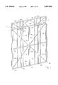
- FIG. 1 illustrates a side wall panel subassembly for the first floor of a multi-story building structure in perspective view
- FIG. 2 illustrates a side wall panel subassembly for the top floor wall of a multi-story building structure in isometric view that is the same width as the subassembly of FIG. 1 and is to be mounted atop that subassembly;
- FIG. 3 illustrates in plan view of the subassemblies depicted in FIGS. 1 and 2 taken along the line 1--1;
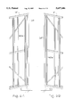
- FIG. 4 is an elevational view of a first floor side wall half panel subassembly, drawn at the same scale as FIGS. 1 and 2, that employs the same construction techniques used in the subassemblies of FIGS. 1 and 2;
- FIG. 4A is a perspective view of the half panel depicted in FIG. 4;
- FIG. 5A illustrates a top floor wall half panel subassembly drawn at the same scale as FIG. 4 and employs the same construction techniques used in the subassemblies of FIGS. 1 and 2;
- FIG. 5B illustrates in plan view of the subassemblies depicted in FIGS. 4 and 5B taken along line 5--5;
- FIG. 5C is a perspective view of of the half panel subassembly depicted in FIG. 5.
- FIG. 6A is a partial perspective view of a side wall end top floor panel
- FIG 6B is a partial perspective view of an end wall top floor panel
- FIG. 7 is an elevational view of a floor truss attached orthogonal to the panel subassembly depicted in FIG. 1 drawn to the same scale;
- FIG. 8 is an elevational view of a gable end roof truss for a sloped roof
- FIG. 9 is an elevational view of an intermediate roof truss for a sloped roof
- FIG. 10 is an elevational view of a short floor truss header for joining ends of floor trusses of a shorter length than that depicted in FIG. 7 drawn to scale equal to that floor truss;
- FIG. 11, 12 and 13 respectively illustrate in elevational view to an equal scale an end roof panel subassembly, an intermediate roof panel subassembly and an intermediate roof half panel subassembly-- which corresponds to those side wall panel subassemblies depicted in FIGS. 4 and 5A, all of which are bolted atop the roof trusses of the building structure.
- FIG. 14 is a partial perspective view illustrating the relationship between the subassemblies of FIGS. 1 and 2 and a floor truss illustrated in FIG. 7 as assembled in a multi-story build structure;
- FIG. 15 is a partial perspective view illustrating the relationship between the subassembly of FIG. 2, the gable end roof truss of FIG. 9 and the end roof panel subassembly of FIG. 11 at a corner wherein the illustrations of FIGS. 6A and 6B are joined and viewed from the opposite side, all as assembled in a multi-story building or single story building;
- FIG. 16 is a partial perspective view illustrating the relationship between the panel subassembly of FIG. 2, the intermediate roof truss of FIG. 8, two of the roof panel subassembly of FIG. 12, and a first type saddle connector member;
- FIG. 17A and 17B show that saddle connector member in elevational and plan view, respectively;
- FIG. 18 is a partial perspective view illustrating the relationship of the subassembly of FIG. 2, the intermediate roof truss of FIG. 8, the roof panel subassembly of FIG. 12 and a second type saddle connector member;
- FIG. 19A and 19B show that saddle connector member in an elevational and plan view, respectively;
- FIG. 20 is a partial section view illustrating the rigid connection of the panel subassembly to a preformed concrete foundation
- FIG. 1 illustrates in isometric view a side wall panel subassembly 2, showing a rigid rectangular frame formed of steel tubing members of, essentially, a square cross section.
- An upper frame member, 3, at the top and a lower frame member, 5, at the bottom are each welded on its under side and upper side surfaces, respectively, at a right angle to the upright or vertical frame member, 7, on the left side, and to the upright or vertical frame member, 9, on the right side.
- a vertical dividing member, 11, located midway between and parallel to the left side, 7, and right side, 9, vertical frame members, is also welded in place between upper frame member 3, and lower frame member 5.
- a pair of horizontal dividing members 13a and 13b are welded between vertical frame member 7 and vertical dividing member 11 and between vertical dividing member 11 and vertical frame member 9.
- the horizontal members in the pair are aligned horizontally and are formed of the same tubular material as the frame members.
- Such horizontal dividing members are also located a short distance below upper frame member 3 to form a floor truss riser region. Since this subassembly is intended to assist in the support of a second story to the building, the narrow rectangular region between upper frame member 3 and horizontal dividing members 13a and 13b provides for the connection of a floor support truss as later discussed.
- Steel tubing used as frame material is not typically cylindrical in shape, but is rectangular in cross section.
- a rectangle is a parallelogram, a four sided figure, in which all angles connecting the sides are at right angles, ninety degrees. Where those sides are equal in length, the figure is referred to as a square.
- Another pair of horizontal dividing members, 15a and 15b, are welded into place between the same three vertical members, 7, 9 and 11 with the members in the pair being aligned horizontally.
- the second pair of members as shown bisect the essentially square area formed by the first pair of horizontal dividing members, 13a and 13b, lower frame member 5, and vertical frame members 7 and 9 within the larger rectangular frame.
- the horizontal dividing members are suitably of the same tubular material as the frame members 3, 5, 7, and 9 and, hence, are the same cross section in shape.
- a series of vertical support members 17a, 17b, 17c, and 17d are welded in place with member 17a and 17b, horizontally spaced evenly between vertical frame member 7 and vertical dividing member 11 and welded between horizontal dividing members 13a and 15a with vertical support members 17c and 17d being horizontally spaced evenly between vertical frame member 9 and vertical dividing member 11 and welded between horizontal dividing members 13b and 15b.
- a like series of vertical support members 19a, 19b, 19c, and 19d are located below horizontal dividing members 15a and 15b with 19a and 19b, being spaced evenly between vertical frame member 7 and vertical dividing member 11 and welded between horizontal dividing member 15a and lower frame member 5, and vertical support members 19c and 19d being spaced evenly between vertical frame member 9 and vertical dividing member 11, and welded between horizontal dividing member 15b and lower frame member 5.
- the vertical support members of the second series are aligned with the corresponding vertical support members of the first series.
- strut 21a is welded at one end to the underside of horizontal dividing member 13a at the juncture of vertical frame member 7 and horizontal dividing member 13a; at its other end it is welded to the left side of vertical dividing member 11 at the juncture of vertical dividing member 11 and horizontal dividing member 15a; strut 21b is welded at one end to the underside of horizontal dividing member 13b at the juncture of vertical frame member 9 and horizontal dividing member 13b; at its other end it is welded to the right side of vertical dividing member 11 at the juncture of vertical dividing member 11 and horizontal dividing member 15b; strut 21c is welded at one end to the left side of vertical frame member 7 at the juncture of vertical frame member 7 and lower
- a pair of short vertical risers 23a and 23b are respectively located equidistant between members 7 and 11 and members 11 and 9 and are welded between upper end member 3 and horizontal members 13a and 13b, respectively.
- a first pair of short vertical support members 25a and 25b are oriented in vertical alignment with their corresponding vertical support member 17a and 17b, respectively, at each side of riser 23a and welded into place as such.
- a like pair of short vertical support members 25c and 25d are oriented in vertical alignment with their corresponding vertical support member 17c and 17d, respectively, at each side of riser 23b and welded into place as such.
- the upper section of the subassembly is further braced by struts 29a, 29b, 29c, and 29d.
- Each of the struts extends from an upper corner area to a diagonally opposite lower corner at the associated vertical riser 23.
- strut 29a is welded to the under side of upper end member 3 at the juncture of vertical frame member 7 and upper end member 3; at the other end, strut 29a is welded to the left side of vertical riser 23aat the juncture of riser 23a and horizontal dividing member 13a.
- Strut 29b is welded to the under side of upper end member 3 at the juncture of vertical dividing member 11 and upper end member 3; at the other end, strut 29b is welded to the right side of vertical riser 23a at the juncture of riser 23a and horizontal dividing member 13a.
- Strut 29c is welded to the under side of upper end member 3 at the juncture of vertical dividing member 11 and upper end member 3; at the other end, strut 29c is welded to the left side of vertical riser 23b at the juncture of riser 23b and horizontal dividing member 13b.
- Strut 29d is welded to the under side of upper end member 3 at the juncture of vertical frame member 9 and upper end member 3; at the other end, strut 29d is welded to the right side of vertical riser 23b at the juncture of riser 23b and horizontal dividing member 13b.
- each of the struts are also welded to the vertical support members across which it traverses.
- strut 21a is welded to vertical support members 17a and 17b.
- the remaining struts are likewise welded into place.
- the result is a rigid assembly that is strong and capable of supporting a large weight and which should not distort as a result of shear force with the subassembly bolted into place along its bottom frame member to the prepared concrete foundation, for example, such as a force applied to the top of vertical frame member 9 pushing toward the bottom of vertical frame member 7.
- the frame members define a somewhat shallow rectanguloid volume, much like the sides of a sand box, with a rectangular front and back face and of short depth equal to the thickness of the frame members.
- the most distant side of that defined volume in the figure which corresponds to the outside surface of the panel subassembly is referred to as the front face. That side of the volume in the figure closest to the reader is referred to as the back face or inside surface of the panel subassembly.
- Each of the vertical support members 17, 19, 25 and strut members 21 and 29 lie within that defined volume.
- FIG. 3 shows the subassembly in plan view and better illustrates the shallow rectanguloid shape.
- the vertical support members are formed of steel tubing and are of a square cross section, but that cross section is smaller in area than the cross section of than of frame members 7 and 9, upper and lower members 3 and 5, vertical dividing member 11, vertical risers 23a and 23b, and horizontal dividing members 15a, 15b, 13a and 13b.
- a flat surface of the vertical support members is flush with the front face of the subassembly, leaving a slight clearance between the opposed flat surface of that vertical support member and the edge of horizontal dividing members 13a and 15a and the frame member 5 on the inside surface of the subassembly.
- That clearance is sufficient to receive the cross section of the diagonal struts 21a, 21b, 21c and 21d, which are smaller still in cross section than the vertical support members.
- the respective struts thus cross over the vertical dividing members with one surface of the strut in contact with that vertical member and welded to it, while the opposed or outer surface of such struts are flush with the back face of the subassembly.
- U-shaped channel members 31a, 31b, 31c, 31d and 31e which serve as posts in application, are carried by the frame and are rigidly connected to that frame, suitably by welds.
- floor trusses hereafter described, are oriented orthogonal to the subassembly and are bolted at end frame members to the vertical dividing member, vertical frame members and vertical risers. The bottom of the truss may abut the top of the posts, which thus serve as supplementary support to that provided by the subassembly frame.
- two rectangular tubular steel mounting brackets 27a and 27b are located just below horizontal dividing members 13a and 13b, respectively, and are rigidly connected between vertical support members 17a and 17b and between vertical support members 17c and 17d, respectively, and are oriented horizontal.
- Channel members 31b and 31d are of a length sufficient to extend between the respective support brackets 27a and 27b and the upper edge bottom frame member 5, leaving the bottom end of the channel recessed form the bottom of the frame subassembly, This creates, leaving the bottom end of the channel recessed form the bottom of the frame subassembly, This creates a step at the bottom end of the panel subassembly, the significance of which is later discussed.
- the remaing channel members are of the same length as the aforementioned channel members.
- Channel members 31b and 31d are of a length sufficient to extend between the respective support brackets 27a and 27b and the upper edge of lower frame member 5 leaving the bottom end of the channel recessed from the bottom of the panel subassembly. This creates a step at the bottom end of the frame, the significance of which is later discussed.
- the remaining channel members are of the same length as the aforementioned channel members and are horizontally aligned. It may be noted that the U-shaped channel members are preferred since they are lower in cost than rectangular cross section tubular steel members and are sufficient to accomplish the task. Additionally, the throat of the channel assists in holding thermal insulation in place, should it be desired to insulate the building. However, steel tubes of rectangular or square cross section may be substituted if desired or required.
- Channel members 31a and 31e are aligned with and overlie left and right vertical frame members 7 and 9, respectively.
- Channel member 31c is aligned with and overlies vertical dividing member 11.
- Channel member 31b is welded to support bracket 27a, horizontal member 15b, struts 21a and 21c, and the lower frame member 5 and is located in horizontal alignment with riser 23a.
- the channel member is located midway between vertical members 7 and 11.
- channel member 31d is located midway between vertical members 9 and 11, in line with vertical riser 23b and is welded to support bracket 27b, horizontal member 15b, struts 21b and 21d, and lower frame member 5.
- channel members 31a and 31e face in toward channel member 31c, while the orientation of the openings of the remaining channel members, 31b, 31c, and 31d are arbitrary. Those opening allow the channel members to at least partially hold thermal insulating material, should it be desired to insulate the walls of the building. It is also recognized that the channel members may be made greater in depth than illustrated in FIG. 1, so as to accommodate a thicker wall section and more thermal insulation material. It is further recognized that the channel members may be made greater in length than illustrated in FIG. 1, in which case support brackets 27a and 27b may be omitted. Instead the top edge of the channel member would be rigidly connected to the bottom edge of horizontal dividing members 13a and 13b, respectively. Channel members 31a and 31e are oriented so as to allow the flat side of the channel to abut an adjacent channel member of and adjacent panel subassembly.
- the associated channel members are spaced a short distance from the vertical side member and do not overlie those frame members as later discussed in connection with FIG. 6.
- Suitable bolt holes are formed in the bottom frame member to anchor the panel subassembly to the concrete foundation.
- Bolt holes are also formed in the vertical risers and the upper end of the vertical dividing member and frame members to provide for the connection of the second floor trusses.
- Additional bolt holes are formed in the vertical frame member extending transversely of the subassembly to permit the subassembly to be bolted to adjacent panel subassemblies during the construction of the building structure.
- the steel tubing elements may be varied in size and thickness in accordance with the present invention.
- the frame members may be formed of 11/2" square eighteen gauge steel
- the vertical support members may be formed of 1" square eighteen gauge steel
- the struts may be formed of 1/2" by 1" eighteen gauge steel.
- the channel members may be formed of 13/8" by 31/4" eighteen gauge steel.
- the wall panel subassembly 4 illustrated in FIG. 2 incorporates the same principal elements heretofore considered in the subassembly of FIG. 1 and serves either as a top floor wall in a multi-story building structure that incorporates the subassembly of FIG. 1 as the wall panel subassembly for the first floor; or as the first floor wall subassembly for a single story structure.
- the subassembly contains the upper horizontal frame member 14, the lower horizontal frame member 16, right and left vertical frame members, 18 and 20, welded together and defining the rectangular frame, vertical dividing member 22, horizontal dividing members 26a and 26b, the first series of vertical support members 28a, 28b, 28c and 28d, and the second series 30a through 30d, and the strut members 32a through 32d. Also, five channel members 42a, 42b, 42c, 42d, and 42e, which serve as posts or support columns are included. To accommodate channel members 42b and 42d, two horizontal rectangular mounting braces are welded between vertical support members 30a and 30b, and 30c and 30d, respectively, a short distance above lower horizontal frame member 16.
- the channel members are positioned on the frame so that they are raised above the frame bottom by a distance that allows insertion not only of the floor truss member, but also insertion of the actual flooring material, such as a sheet of wood or metal floor decking to receive light weight concrete or the like. This permits the bottom of the channel member to abut the finished floor. It is recognized that in other embodiments the length of the channel member may be greater so that its bottom extends to the top surface of the lower horizontal frame member 16, in which the channels bottom end would abut the top of the floor truss.
- the foregoing panel subassembly is formed of steel tubing of the same square cross section as in the preceding figure, which, for one, minimizes the variety of steel materials that the manufacturer is required to procure and inventory.
- the foregoing are rigidly connected with welds in the same manner and relationship as the subassembly of FIG. 1 with the exception that the upper end of the first series of vertical support members, the vertical dividing member and the diagonal struts are welded to the upper frame member 14, instead of the horizontal dividing members necessitated by the riser section in the prior subassembly.
- the channel members in this panel subassembly includes two types of saddle connectors 40a through 40e, each of which is connected to the upper member 14 and a respective channel member 42a through 42e suitably by welds.
- Each saddle member contains bolt openings intended to permit an end of the roof truss, which when assembled extend orthogonal to the subassembly, to be bolted to the panel subassembly.
- One type of saddle member is located on the right most channel member, 42a, and left most channel member, 42e, and a second type is connected to the intermediate ones, 42b through 42d, as later herein described.
- the saddle member extends slightly above the end of the respective channel member to the top edge of the frame.
- FIG. 3 illustrates in an equal scale a section of FIG. 1 taken along the line 1--1 in FIG. 1.
- vertical frame members vertical frame members 7 and 9 define the width of the shallow rectanguloid volume.
- Vertical support members 17a through 17d have their outer surface flush with, that is lying in the same plan as the outer surface of the rectanguloid volume defined by the straight line representing the horizontal dividing members 15a and 15b, and lower frame member 5 below.
- the struts, such as strut 21a has its outer surface flush with the inner face of the rectanguloid volume and its opposed face in contact with the vertical support members.
- the appended channel members 31a through 31e are seen to protrude orthogonal from the inner surface of the rectanguloid volume.
- FIGS. 1 and 2 show a perspective view of FIGS. 4A and 5A, respectively, wherein the channel members are added to illustrate their position and orientation.
- the buildings wall is essentially required to be a multiple number of full panel subassemblies plus a half panel subassembly in length.
- FIG. 5B shows a section of FIG. 5A taken along the line 5--5 in FIG. 5A, with the channel members added to illustrate their position and orientation. Since the half panel subassembly does not include a vertical dividing member corresponding to vertical dividing member 22 of FIG. 2, channel member 42b' is located midway between the vertical frame members, 7" and 9". The construction and materials used in this half panel subassembly are the same as that in FIGS. 1 and 2 and need not be further described. It should be noted that 6 of FIG. 4 depicts a first floor wall panel subassembly while 8 of FIG. 5A depicts the corresponding second floor panel subassembly aligned and overlying 6.
- FIGS. 1 and 2 are to be located at a corner of the building in which a vertical frame member of either subassembly is to be at a corner and abut a corresponding vertical frame member of another like subassembly oriented at a fight angle thereto, the channel members, which overlie such vertical frame members must be displaced in position as the channels would interfere with one another and cannot share the same space. Accordingly, the panel subassembly for those corner locations differ slightly in construction, by essentially displacing the end channel member in position as illustrated in the partial perspective views of FIGS. 6A and 6B to which reference is made.
- FIG. 6A shows a section of the end of and upper floor panel subassembly in which channel member 40e' is laterally displaced a predetermined distance, D1, from the vertical frame member 20'. This is for a corner at the side wall of the building structure, where the wall underlies the eaves of the roof.
- FIG. 6B shows a similar view of an upper story wall assembly for a corner at the end wall of the building structure, one which is parallel to the roof truss and orthogonal to the adjacent side wall corner panel.
- the channel member 40e" is laterally displaced a predetermined distance, D2, from vertical frame member 20".
- the channel member of the side wall subassembly is displaced a slightly larger distance from the end of the associated vertical frame member, meaning D1>D2.
- FIG. 7 illustrates a typical floor truss, 10, in elevational view and to a reduced scale.
- the truss is a rectangular section of short height, corresponding in height to the riser section of the subassembly in FIG. 1.
- the truss is formed of the same rectangular cross section tubular steel employed in the construction of the frame portion of the wall panel subassemblies.
- the truss contains outer frame members, intermediate vertical supports and diagonal struts, for bracing between the supports, as illustrated and are welded together to form a rigid skeleton.
- the aforementioned vertical supports are spaced in a manner so as to be consistent with the spacing of the vertical frame members within the subassemblies comprising the end wall of a building.
- the floor truss 10 is indicative of an end wall assembly of a building containing two full wall panel subassemblies and one half panel subassembly, wherein the full panels lie to each side of the half panel in the middle.
- the length of the truss may be equal to the distance between the side walls or, if greater width is desired, one or more truss may be joined together by bolting them in line to assemble a truss of greater length as taught in the prior Ressel Patent, all the while maintaining consistency between the vertical members of the end wall assembly and the vertical supports of the floor truss. It should be noted that the joining together or splicing inline of trusses is determined by the desire to maintain easily transportable component sizes in a building structure.
- FIG. 8 illustrates a gable end roof truss, 12, in elevational view.
- FIG. 9 is a like view of an intermediate roof truss, 22 also in elevational view.
- the trusses are of a triangular shape and define the slope of a sloped roof.
- a roof truss may be fabricated in one piece as illustrated, or, two or three pieces that are bolted together at the building site prior to installation.
- the roof trusses are formed of the same tubular material as the frame portion of the wall panel subassemblies and are essentially the same as that construction described in the prior Ressel Patent, which may be referred to for additional details.
- a short floor truss, 24, is illustrated in elevational view in FIG. 10.
- This truss is bolted between separate floor trusses or between a floor truss and an end wall of a building and serves as and end or header to intermediate, short floor trusses, not illustrated, that are bolted at an end orthogonal to this truss.
- this is used in those buildings in which one desires to form a floor opening for a stairwell.
- some floor trusses may extend across the full width of the building, to form an opening in the floor a number of short floor trusses are used, with the ends thereof bolted to the short floor truss header 24.
- the length of the short floor truss is determined by the desired opening's width. That desired width is augmented in consideration of maintaining the consistency of the alignment of the vertical members within the end wall assembly and the vertical members of all floor trusses.
- the desired length of the opening is augmented in consideration of the spacing of the floor trusses.
- the trusses, and header(s) framing an opening for stairs are doubled, hence, two floor truss headers, 24 of FIG. 10. are bolted to one another as are two floor trusses, 10 of FIG. 7, offering increased bearing capacity of the floor around the opening.
- FIG. 11 A roof panel, 34, the skeletal frame that is to be placed atop the roof trusses to support the covering roof materials applied in finishing the building, is illustrated in FIG. 11 in elevational view.
- the roof panel is seen to contain the same elements as those found to be successful in the wall panel subassemblies earlier described. It also contains two narrow rectangular sections that are to provide the overhang found in a building structure with a sloped roof. Assuming that a building structure is to be of a length that requires more than two roof panel in a side by side relationship, intermediate roof panels, those located between the front and back ends of the building, do not include the rectangular section that defines the overhang at the end wall, as shown by 36 of FIG. 12, but otherwise are of the same construction illustrated.
- FIG. 11 presents a roof end panel subassembly 34, which is placed over the gable end roof truss at a corner of a building system.
- the subassembly includes short rectangular portions on its bottom, to provide for overhang of the building's side wall and on its left side, to provide for overhang of the building's end wall.
- Subassembly 34 contains the vertical supports and struts, all of which fit within the shallow rectanguloid volume defined by the outer frame members as earlier described in connection with the wall panel subassemblies of FIGS. 1 and 2.
- the intermediate roof panel subassembly 36 of FIG. 12 only the bottom portion, that which provides for overhang of the building's side wall is included.
- the width of the intermediate roof panel subassemblies is equal to the width of the wall panel subassemblies 2 and 4 in FIGS. 1 and 2, respectively.
- a like half roof panel subassembly, 38 is illustrated in FIG. 13.
- the roof panel subassembly are formed of the same steel tubing as described in connection with wall panel subassemblies 2 and 4 in FIGS. 1 and 2, respectively, with the same cross section size for the corresponding elements.
- the roof panel subassemblies provide the support for any finish roofing material desired and its underlayment. Those materials are conventional and need not be described, although one may reference the Ressel Patent for additional details as needed.
- FIG. 14 Views a portion of the building frame assembly from a vantage point just above the second story floor trusses.
- the first floor wall panel subassembly of FIG. 1, the second story wall panel subassembly of FIG. 2 and the floor truss of FIG. 4, as well as like adjacent subassemblies, not separately numbered for clarity, are assembled together as illustrated in the partial view.
- the elements appearing in this view are identified by the same numbers used in preceding views.
- FIG. 15 As assembled in the multi-story building, two of the second story wall panel subassembly of FIG. 2, as described in association with FIGS. 6A and 6B, the roof trusses 12 and 22 of FIGS. 8 and 9, respectively, and the end roof panel subassembly, 34, of FIG. 11 are assembled together as illustrated in the partial perspective view of FIG. 15 to which references may be briefly made.
- the perspective of the view is from the outside of the building slightly above the second story wall assembly. This view aids in the understanding of the conjunction of the wall panel subassemblies at a corner of a building by showning the opposed view, albeit assembled, of those shown in FIGS. 6A and 6B. To ease in understanding the elements are identified by the same number used in the preceding views.
- FIG. 16 illustrates, in partial perspective view, looking up toward the roof frame, the conjunction of the upper floor wall panel subassemblies 4 and 4', roof truss 22, roof panel subassemblies 36 and 36', and a first type saddle connector 40e in an assembled relationship.
- Saddle member 40e comprises one half of the saddle connector prior to assembly. It is fabricated from a flat rectangular shaped piece of plate steel of a predetermined thickness, that is formed into one half of a U-shaped channel, similar to an ⁇ L ⁇ , and welded into place at the top of channel member 42e and upper end member 14, of wall panel subassembly 4. As better illustrated in the end view of FIG. 17A and the top view of FIG.
- saddle member 40e cooperates with a like saddle member 40a', which is welded to the corresponding channel member 42a' and upper end member 14', of the adjacent wall panel subassembly 4'.
- saddle members 40e and 40a' form the U-shaped saddle connector to receive the elongate horizontal member of the overlying truss 22.
- Each saddle members contains two bolt hole openings. Bolts 43a and 43b, in FIGS.
- FIG. 18 illustrates a like partial perspective view, looking up toward the roof frame, the conjunction of the upper floor wall panel subassembly 4, roof truss 22, roof panel subassembly 36', and a second type saddle connector, 40c in an assembled relationship.
- Saddle member 40c is essentially the assembled saddle members 40e and 40a' of FIG. 16 and is welded to the top of channel member 42c, which is attached to the vertical dividing member 22 of FIG. 2, and the upper end member 14.
- Saddle member 40c is a rectangular shaped piece of plate steel formed into a U-shaped channel wherein the two flanges each contain a pair of bolt holes. As illustrated in the end view of FIG.
- bolts 45a and 45b are inserted through saddle member 40c and the elongate horizontal member of roof truss 22 and in a compressive manner rigidly attaches the elongate horizontal member of roof truss 22' to the saddle connector 40c of wall panel subassembly 4.
- each panel assembly used in the assembly of the first floor is mounted to the preformed foundation and to the adjacent panel assembly by bolts.
- the preformed foundation at its perimeter contains a depressed portion, or step, that is recessed below the finished concrete floor so as to accommodate the lower member 5 of a wall panel subassembly and allow the channel member 42c to rest upon the finished concrete floor.
- Two bolts, such as bolt 47, are anchored in that depressed portion as illustrated.
- the bottom of the subassembly rests on the bottom of the depressed portion, while the bottom end of the posts of that subassembly are elevated and rest upon the finished concrete floor.
- the subassemblies may be treated with an ant-corrosive wash, and painted with a chromate primer and a finish coat, if necessary, prior to assembly.
- the first floor wall panel subassemblies are placed in upstanding position on the foundation and are bolted to the foundation, as partially illustrated in FIG. 20.
- Adjacent wall panel subassemblies are also bolted to one another, with the appropriate side and end corner type wall panel subassemblies, as mentioned in connection with the discussion of FIGS. 6A and 6B, located at the buildings corners. Any of the subassemblies containing windows or doors are appropriately located in the series as required by the particular building design.
- the floor trusses discussed in connection with FIG.
- any half panel subassemblies as in FIG. 5A and any subassemblies containing windows or doors for the second floor are appropriately located according to the building design and are bolted to the underlying first floor wall panel subassemblies, leaving a slight clearance between the foot of the channel members of the second floor wall panel subassemblies, as illustrated by channel member 42d and 42e of FIG. 14.
- Gable end roof trusses and intermediate roof trusses of FIGS. 8 and 9 are mounted between parallel side walls and orthogonal thereto, resting the ends of the trusses within in the appropriate saddle connector, rigidly connected thereto, atop the associated channel member as illustrated in FIGS. 16 and 18.
- the various roof panel subassemblies of FIGS. 11, 12 and 13 are mounted atop the roof trusses and are bolted thereto, to one another and to the side wall subassemblies to essentially complete the building structure, readying same for finishing. And an appropriate stairwell, not illustrated, extending between the second and first floors can then be installed.
- an appropriate number of sheets of flooring material are attached to the tops of the floor trusses, appropriately with self drilling screws or the like, placing the edge thereof within the clearance under the foot of the channel members on the second floor wall panel subassemblies.
- the clearance may allow for a loose fit in wherein the channel's foot end does not contact the flooring material, or alternatively, may allow a tight fit so that the channel's foot end remains in contact with that material for providing additional support to the channel member.
- exterior sheeting is attached to the outside face of the panel subassemblies, the separation between vertical support members, vertical frame members, and vertical dividing members being a customary industry spacing or otherwise being know to that person performing the labor.
- Thermal insulation blankets or other thermal insulation material may be added between the channels on the inside face of the subassemblies, with the blankets or the like oriented vertically. Dry wall panels are then fastened to the flange of the channel members with self drilling screw or the like, with the spacing between the channel members being a customary industry spacing or otherwise know to the person performing that labor, to finish the interior walls of both the upper and lower floors. Appropriate sheets of roofing material, standard plywood, wafer board, cement board and the like are place upon the roof panel subassemblies and fastened down with self drilling screws or the like. As is appreciated, the preformed subassemblies provide quick and easy assembly of a strong, integrated, and reliable structural frame.
Abstract
Description
Claims (21)
Priority Applications (1)
| Application Number | Priority Date | Filing Date | Title |
|---|---|---|---|
| US08/149,477 US5657606A (en) | 1993-11-09 | 1993-11-09 | Building system |
Applications Claiming Priority (1)
| Application Number | Priority Date | Filing Date | Title |
|---|---|---|---|
| US08/149,477 US5657606A (en) | 1993-11-09 | 1993-11-09 | Building system |
Publications (1)
| Publication Number | Publication Date |
|---|---|
| US5657606A true US5657606A (en) | 1997-08-19 |
Family
ID=22530461
Family Applications (1)
| Application Number | Title | Priority Date | Filing Date |
|---|---|---|---|
| US08/149,477 Expired - Lifetime US5657606A (en) | 1993-11-09 | 1993-11-09 | Building system |
Country Status (1)
| Country | Link |
|---|---|
| US (1) | US5657606A (en) |
Cited By (54)
| Publication number | Priority date | Publication date | Assignee | Title |
|---|---|---|---|---|
| US5867964A (en) * | 1995-12-20 | 1999-02-09 | Perrin; Arthur | Prefabricated construction panels and modules for multistory buildings and method for their use |
| US6003280A (en) * | 1996-08-02 | 1999-12-21 | Inter-Steel Structures, Inc. | Modular frame building |
| US6073413A (en) * | 1994-06-28 | 2000-06-13 | Tongiatama; Paul P. | Structural bracing for buildings |
| US6098358A (en) * | 1997-05-15 | 2000-08-08 | Steelcase Development Inc. | Knock-down portable partition system |
| US6152428A (en) * | 1997-12-18 | 2000-11-28 | Simioni; Lino | Fence system |
| US6185898B1 (en) * | 1998-07-10 | 2001-02-13 | Robert F. Pratt | High strength wall frames and system utilizing same |
| WO2001046531A2 (en) * | 1999-12-21 | 2001-06-28 | Inter-Steel Structures, Inc. | Modular building frame |
| US6276654B1 (en) | 1997-12-29 | 2001-08-21 | Thomas Allen Perkins | Wall panel mount |
| US6301846B1 (en) | 1996-12-24 | 2001-10-16 | Steelcase Development Inc. | Knock-down portable partition system |
| US6308469B1 (en) | 1999-10-15 | 2001-10-30 | Shear Force Systems Inc. | Shear wall panel |
| US6460305B1 (en) | 1998-03-03 | 2002-10-08 | Steelmasters Inc. | Basement wall system |
| US6484460B2 (en) | 1998-03-03 | 2002-11-26 | Vanhaitsma Steve J. | Steel basement wall system |
| US20030009964A1 (en) * | 2001-06-21 | 2003-01-16 | Shear Force Wall Systems Inc. | Prefabricated shearwall having improved structural characteristics |
| US6546684B2 (en) | 1998-04-15 | 2003-04-15 | Steelcase Development Corporation | Partition panel |
| US20030167722A1 (en) * | 2002-03-08 | 2003-09-11 | Klein James A. | Versa-track wall/floor joist assembly and method |
| US20040068947A1 (en) * | 1997-06-12 | 2004-04-15 | Commins Alfred D. | Diaphragm with perimeter edging on structural panels |
| US6826885B2 (en) * | 2002-02-06 | 2004-12-07 | Stephen S. Raskin | System for reinforcing extruded beams |
| US6892504B1 (en) * | 2002-01-28 | 2005-05-17 | The Steel Network, Inc. | Wall structure with corner connectors |
| US20050144855A1 (en) * | 1996-12-24 | 2005-07-07 | Waalkes Michael L. | Knock-down portable partition system |
| US6931364B1 (en) * | 2000-01-14 | 2005-08-16 | G. Douglas Anturna | Volume detailed building structure |
| US20050193678A1 (en) * | 2005-04-25 | 2005-09-08 | Cortek, Inc. | Load-bearing system for fill material structure formation |
| US20050235594A1 (en) * | 2004-04-21 | 2005-10-27 | John Hildreth | Framing system |
| US20070022701A1 (en) * | 2005-07-29 | 2007-02-01 | Surowiecki Matt F | Diagonally braced sheet metal framing wall |
| US20070256392A1 (en) * | 2006-04-14 | 2007-11-08 | Mifsud Vincent D | Automatic pinning process for building panel assembly |
| US20080104894A1 (en) * | 2006-11-07 | 2008-05-08 | Kramer William J | Pre-fabricated post frame panel |
| US20090044480A1 (en) * | 2007-02-16 | 2009-02-19 | Intersteel Structures, Inc. | Insulated Modular Building Frame |
| US20090272051A1 (en) * | 2008-05-05 | 2009-11-05 | Weldon Saylor Sipe | Prefabricated temporary building system consisting of interchangeable panels and a plurality of connectors used to construct walls, roofs, and floors without the need of fasteners, or tools or heavy construction equipment |
| US20100011677A1 (en) * | 2006-12-08 | 2010-01-21 | Bancha Kampanatsanyakorn | Industrialized construction system and method |
| US7665251B1 (en) * | 2004-06-09 | 2010-02-23 | Steven Lang | Structural steel framed houses with gable end frames, intermediate frames, and wall and roof panels having perimeters of C-shaped steel channels |
| US20100058689A1 (en) * | 2006-12-04 | 2010-03-11 | Ronald Weldon Campbell | Modular building for deployment in disaster regions |
| US7788878B1 (en) * | 2008-04-03 | 2010-09-07 | The Steel Network, Inc. | Device and method for bracing a wall structure |
| US20100287848A1 (en) * | 2009-05-14 | 2010-11-18 | Technostructur Inc. | Wall module, housing module and building made of such wall module |
| US20110146201A1 (en) * | 2009-12-18 | 2011-06-23 | John Louis Vanker | Panelized structural system for building construction |
| WO2011144941A2 (en) | 2010-05-21 | 2011-11-24 | Alan Dawson | Pre-fabricated building structure |
| US8112968B1 (en) | 1995-12-14 | 2012-02-14 | Simpson Strong-Tie Company, Inc. | Pre-assembled internal shear panel |
| US20120311955A1 (en) * | 2011-06-08 | 2012-12-13 | Brian Wade Johnson | Construction panel and related methods |
| US20130008116A1 (en) * | 2011-07-06 | 2013-01-10 | Turner Iii Henry Clay | Construction assembly including stackable substructure frames and distinct combined tie connection and reinforcing means |
| US8397454B2 (en) | 1997-11-21 | 2013-03-19 | Simpson Strong-Tie Company, Inc. | Building wall for resisting lateral forces |
| US8528268B1 (en) * | 2010-12-02 | 2013-09-10 | Component Manufacturing Company | Trilateral bracing structure for reinforcing a building frame structure |
| US8688411B2 (en) | 2009-12-18 | 2014-04-01 | John Louis Vanker | Method and system of using standardized structural components |
| US8739475B2 (en) | 2010-08-06 | 2014-06-03 | Blu Homes, Inc. | Foldable building units |
| US8943759B2 (en) | 2011-01-26 | 2015-02-03 | Blu Homes, Inc. | Dual-side unfoldable building modules |
| US9009011B2 (en) | 2009-12-18 | 2015-04-14 | Patco, Inc. | Integrated construction platform |
| WO2017030453A1 (en) * | 2015-08-14 | 2017-02-23 | Jacinto Ramon P | Typhoon resilient pre-fabricated steel frame housing |
| WO2017063041A1 (en) * | 2015-10-13 | 2017-04-20 | Bluescope Steel Limited | Steel frame system |
| US20190100908A1 (en) * | 2017-10-03 | 2019-04-04 | 500 Group, Inc. | Customizable Transportable Structures and Components Therefor |
| US20200080297A1 (en) * | 2018-08-21 | 2020-03-12 | John David Wright | Insulatable, Insulative Framework Apparatus and Methods of Making and Using Same |
| US10683661B2 (en) | 2018-01-30 | 2020-06-16 | William H. Bigelow | Building module with pourable foam and cable |
| US11118344B2 (en) | 2019-02-14 | 2021-09-14 | Build Ip Llc | Foldable building structures with utility channels and laminate enclosures |
| US20210301528A1 (en) * | 2020-03-27 | 2021-09-30 | Nexii Building Solutions Inc. | Systems and methods for constructing a single-storey building |
| US20220136229A1 (en) * | 2020-11-04 | 2022-05-05 | Kyle Tompane | Frame arrangement for wood framed buildings |
| US20220220736A1 (en) * | 2020-10-29 | 2022-07-14 | Guangdong Oppo Mobile Telecommunications Corp., Ltd. | Wall panel apparatus |
| US11718984B2 (en) | 2021-01-12 | 2023-08-08 | Build Ip Llc | Liftable foldable transportable buildings |
| US11739547B2 (en) | 2021-01-12 | 2023-08-29 | Build Ip Llc | Stackable foldable transportable buildings |
Citations (10)
| Publication number | Priority date | Publication date | Assignee | Title |
|---|---|---|---|---|
| US1748794A (en) * | 1928-06-04 | 1930-02-25 | White Castle System | Portable building |
| US1818418A (en) * | 1928-02-04 | 1931-08-11 | Mcclintic Marshall Corp | Steel frame house construction |
| US1858701A (en) * | 1929-07-25 | 1932-05-17 | Armstrong Cork Co | Building construction |
| US3611664A (en) * | 1969-08-11 | 1971-10-12 | Edmund C Barbera | Building wall construction |
| US3998016A (en) * | 1975-03-13 | 1976-12-21 | H. H. Robertson Company | Blow-in/blow-out wall structure |
| US4235054A (en) * | 1977-11-14 | 1980-11-25 | Angeles Metal Trim Co. | Building wall structure |
| US4455792A (en) * | 1981-02-10 | 1984-06-26 | Roland Pasco | Process for erecting a building and building erected in accordance therewith |
| US4559748A (en) * | 1983-01-28 | 1985-12-24 | Ressel Dennis E | Pre-formed building systems |
| US4817356A (en) * | 1984-02-08 | 1989-04-04 | Scott Christopher R | Construction systems and elements thereof |
| US4890437A (en) * | 1987-07-09 | 1990-01-02 | Quaile Allan T | Segmented arch structure |
-
1993
- 1993-11-09 US US08/149,477 patent/US5657606A/en not_active Expired - Lifetime
Patent Citations (10)
| Publication number | Priority date | Publication date | Assignee | Title |
|---|---|---|---|---|
| US1818418A (en) * | 1928-02-04 | 1931-08-11 | Mcclintic Marshall Corp | Steel frame house construction |
| US1748794A (en) * | 1928-06-04 | 1930-02-25 | White Castle System | Portable building |
| US1858701A (en) * | 1929-07-25 | 1932-05-17 | Armstrong Cork Co | Building construction |
| US3611664A (en) * | 1969-08-11 | 1971-10-12 | Edmund C Barbera | Building wall construction |
| US3998016A (en) * | 1975-03-13 | 1976-12-21 | H. H. Robertson Company | Blow-in/blow-out wall structure |
| US4235054A (en) * | 1977-11-14 | 1980-11-25 | Angeles Metal Trim Co. | Building wall structure |
| US4455792A (en) * | 1981-02-10 | 1984-06-26 | Roland Pasco | Process for erecting a building and building erected in accordance therewith |
| US4559748A (en) * | 1983-01-28 | 1985-12-24 | Ressel Dennis E | Pre-formed building systems |
| US4817356A (en) * | 1984-02-08 | 1989-04-04 | Scott Christopher R | Construction systems and elements thereof |
| US4890437A (en) * | 1987-07-09 | 1990-01-02 | Quaile Allan T | Segmented arch structure |
Cited By (101)
| Publication number | Priority date | Publication date | Assignee | Title |
|---|---|---|---|---|
| US6073413A (en) * | 1994-06-28 | 2000-06-13 | Tongiatama; Paul P. | Structural bracing for buildings |
| US9085901B2 (en) | 1995-12-14 | 2015-07-21 | Simpson Strong-Tie Company, Inc. | Pre-assembled internal shear panel |
| US8112968B1 (en) | 1995-12-14 | 2012-02-14 | Simpson Strong-Tie Company, Inc. | Pre-assembled internal shear panel |
| US5867964A (en) * | 1995-12-20 | 1999-02-09 | Perrin; Arthur | Prefabricated construction panels and modules for multistory buildings and method for their use |
| US6003280A (en) * | 1996-08-02 | 1999-12-21 | Inter-Steel Structures, Inc. | Modular frame building |
| US20050144855A1 (en) * | 1996-12-24 | 2005-07-07 | Waalkes Michael L. | Knock-down portable partition system |
| US6301846B1 (en) | 1996-12-24 | 2001-10-16 | Steelcase Development Inc. | Knock-down portable partition system |
| US6098358A (en) * | 1997-05-15 | 2000-08-08 | Steelcase Development Inc. | Knock-down portable partition system |
| US20040068947A1 (en) * | 1997-06-12 | 2004-04-15 | Commins Alfred D. | Diaphragm with perimeter edging on structural panels |
| US8397454B2 (en) | 1997-11-21 | 2013-03-19 | Simpson Strong-Tie Company, Inc. | Building wall for resisting lateral forces |
| US8479470B2 (en) | 1997-11-21 | 2013-07-09 | Simpson Strong-Tie Company, Inc. | Building wall for resisting lateral forces |
| US6152428A (en) * | 1997-12-18 | 2000-11-28 | Simioni; Lino | Fence system |
| US6276654B1 (en) | 1997-12-29 | 2001-08-21 | Thomas Allen Perkins | Wall panel mount |
| US6460305B1 (en) | 1998-03-03 | 2002-10-08 | Steelmasters Inc. | Basement wall system |
| US6484460B2 (en) | 1998-03-03 | 2002-11-26 | Vanhaitsma Steve J. | Steel basement wall system |
| US6546684B2 (en) | 1998-04-15 | 2003-04-15 | Steelcase Development Corporation | Partition panel |
| US6185898B1 (en) * | 1998-07-10 | 2001-02-13 | Robert F. Pratt | High strength wall frames and system utilizing same |
| US6308469B1 (en) | 1999-10-15 | 2001-10-30 | Shear Force Systems Inc. | Shear wall panel |
| WO2001046531A2 (en) * | 1999-12-21 | 2001-06-28 | Inter-Steel Structures, Inc. | Modular building frame |
| US7992352B2 (en) * | 1999-12-21 | 2011-08-09 | Bonds Delton J | Modular building frame |
| US6460297B1 (en) | 1999-12-21 | 2002-10-08 | Inter-Steel Structures, Inc. | Modular building frame |
| WO2001046531A3 (en) * | 1999-12-21 | 2001-11-15 | Inter Steel Structures Inc | Modular building frame |
| US6931364B1 (en) * | 2000-01-14 | 2005-08-16 | G. Douglas Anturna | Volume detailed building structure |
| US6931804B2 (en) * | 2001-06-21 | 2005-08-23 | Shear Force Wall Systems Inc. | Prefabricated shearwall having improved structural characteristics |
| US20030009964A1 (en) * | 2001-06-21 | 2003-01-16 | Shear Force Wall Systems Inc. | Prefabricated shearwall having improved structural characteristics |
| US6892504B1 (en) * | 2002-01-28 | 2005-05-17 | The Steel Network, Inc. | Wall structure with corner connectors |
| US6941718B1 (en) * | 2002-01-28 | 2005-09-13 | The Steel Network, Inc. | Wall structure |
| US6826885B2 (en) * | 2002-02-06 | 2004-12-07 | Stephen S. Raskin | System for reinforcing extruded beams |
| US20030167722A1 (en) * | 2002-03-08 | 2003-09-11 | Klein James A. | Versa-track wall/floor joist assembly and method |
| WO2005106145A3 (en) * | 2004-04-21 | 2007-01-04 | Engineered Framing Systems | Improved framing system |
| WO2005106145A2 (en) * | 2004-04-21 | 2005-11-10 | Engineered Framing Systems | Improved framing system |
| US20050235594A1 (en) * | 2004-04-21 | 2005-10-27 | John Hildreth | Framing system |
| US7299596B2 (en) * | 2004-04-21 | 2007-11-27 | John Hildreth | Framing system |
| US20080066418A1 (en) * | 2004-04-21 | 2008-03-20 | John Hildreth | Framing system |
| US7665251B1 (en) * | 2004-06-09 | 2010-02-23 | Steven Lang | Structural steel framed houses with gable end frames, intermediate frames, and wall and roof panels having perimeters of C-shaped steel channels |
| US20050193678A1 (en) * | 2005-04-25 | 2005-09-08 | Cortek, Inc. | Load-bearing system for fill material structure formation |
| US20110016800A1 (en) * | 2005-04-25 | 2011-01-27 | Cortek, Inc. | Load-Bearing System for Fill Material Structure Formation |
| US7805908B2 (en) | 2005-04-25 | 2010-10-05 | Cortek, Inc. | Load-bearing system for fill material structure formation |
| US20070022701A1 (en) * | 2005-07-29 | 2007-02-01 | Surowiecki Matt F | Diagonally braced sheet metal framing wall |
| US7894920B2 (en) | 2006-04-14 | 2011-02-22 | Genesis TP, Inc. | Information technology process for prefabricated building panel assembly |
| US20070264108A1 (en) * | 2006-04-14 | 2007-11-15 | Mifsud Vincent D | Bi-directional roller table |
| US20070260345A1 (en) * | 2006-04-14 | 2007-11-08 | Mifsud Vincent D | Component manufacturing system for a prefabricated building panel |
| US20070262040A1 (en) * | 2006-04-14 | 2007-11-15 | Mifsud Vincent D | Overhead gantry for use in building panel construction |
| US20070265724A1 (en) * | 2006-04-14 | 2007-11-15 | Mifsud Vincent D | Information technology process for prefabricated building panel assembly |
| US20070264107A1 (en) * | 2006-04-14 | 2007-11-15 | Mifsud Vincent D | Material transport system for building panel assembly |
| US20070271870A1 (en) * | 2006-04-14 | 2007-11-29 | Mifsud Vincent D | Manufacturing method for a prefabricated building panel |
| US7835810B2 (en) | 2006-04-14 | 2010-11-16 | Genesistp, Inc. | Tools and methods for designing a structure using prefabricated panels |
| US20070256392A1 (en) * | 2006-04-14 | 2007-11-08 | Mifsud Vincent D | Automatic pinning process for building panel assembly |
| US20070261318A1 (en) * | 2006-04-14 | 2007-11-15 | Mifsud Vincent D | Kit for manufacturing an enclosure from prefabricated panels |
| US20080104894A1 (en) * | 2006-11-07 | 2008-05-08 | Kramer William J | Pre-fabricated post frame panel |
| US20100058689A1 (en) * | 2006-12-04 | 2010-03-11 | Ronald Weldon Campbell | Modular building for deployment in disaster regions |
| US20100011677A1 (en) * | 2006-12-08 | 2010-01-21 | Bancha Kampanatsanyakorn | Industrialized construction system and method |
| US20090044480A1 (en) * | 2007-02-16 | 2009-02-19 | Intersteel Structures, Inc. | Insulated Modular Building Frame |
| AU2008219174B2 (en) * | 2007-02-16 | 2014-12-11 | Issi Holding Company, Llc | Insulated modular building frame |
| US8381484B2 (en) * | 2007-02-16 | 2013-02-26 | Issi Holding Company, Llc | Insulated modular building frame |
| US7788878B1 (en) * | 2008-04-03 | 2010-09-07 | The Steel Network, Inc. | Device and method for bracing a wall structure |
| US20090272051A1 (en) * | 2008-05-05 | 2009-11-05 | Weldon Saylor Sipe | Prefabricated temporary building system consisting of interchangeable panels and a plurality of connectors used to construct walls, roofs, and floors without the need of fasteners, or tools or heavy construction equipment |
| US20100287848A1 (en) * | 2009-05-14 | 2010-11-18 | Technostructur Inc. | Wall module, housing module and building made of such wall module |
| US8276328B2 (en) | 2009-05-14 | 2012-10-02 | Technostructur Inc. | Wall module, housing module and building made of such wall module |
| US9081916B2 (en) | 2009-12-18 | 2015-07-14 | Patco, Llc | Method and system of using standardized structural components |
| US9424375B2 (en) | 2009-12-18 | 2016-08-23 | Patco, Llc | Method and system of using standardized structural components |
| US8528294B2 (en) * | 2009-12-18 | 2013-09-10 | Patco, Llc | Panelized structural system for building construction |
| US9677272B2 (en) | 2009-12-18 | 2017-06-13 | Patco, Llc | Panelized structural system for building construction |
| US8688411B2 (en) | 2009-12-18 | 2014-04-01 | John Louis Vanker | Method and system of using standardized structural components |
| US9424374B2 (en) | 2009-12-18 | 2016-08-23 | Patco, Llc | Integrated construction portal |
| US8887472B2 (en) * | 2009-12-18 | 2014-11-18 | Patco, LL | Panelized structural system for building construction |
| US20110146201A1 (en) * | 2009-12-18 | 2011-06-23 | John Louis Vanker | Panelized structural system for building construction |
| US9009011B2 (en) | 2009-12-18 | 2015-04-14 | Patco, Inc. | Integrated construction platform |
| WO2011144941A2 (en) | 2010-05-21 | 2011-11-24 | Alan Dawson | Pre-fabricated building structure |
| US8739475B2 (en) | 2010-08-06 | 2014-06-03 | Blu Homes, Inc. | Foldable building units |
| US8528268B1 (en) * | 2010-12-02 | 2013-09-10 | Component Manufacturing Company | Trilateral bracing structure for reinforcing a building frame structure |
| US8943759B2 (en) | 2011-01-26 | 2015-02-03 | Blu Homes, Inc. | Dual-side unfoldable building modules |
| US20120311955A1 (en) * | 2011-06-08 | 2012-12-13 | Brian Wade Johnson | Construction panel and related methods |
| US10184241B2 (en) * | 2011-06-08 | 2019-01-22 | Brian W. Johnson | Construction panel and related methods |
| US20130008116A1 (en) * | 2011-07-06 | 2013-01-10 | Turner Iii Henry Clay | Construction assembly including stackable substructure frames and distinct combined tie connection and reinforcing means |
| WO2017030453A1 (en) * | 2015-08-14 | 2017-02-23 | Jacinto Ramon P | Typhoon resilient pre-fabricated steel frame housing |
| WO2017063041A1 (en) * | 2015-10-13 | 2017-04-20 | Bluescope Steel Limited | Steel frame system |
| AU2016340035B2 (en) * | 2015-10-13 | 2022-03-31 | Bluescope Steel Limited | Steel frame system |
| US10688906B2 (en) * | 2017-10-03 | 2020-06-23 | 500 Group, Inc. | Customizable transportable structures and components therefor |
| US20190100908A1 (en) * | 2017-10-03 | 2019-04-04 | 500 Group, Inc. | Customizable Transportable Structures and Components Therefor |
| US20200269744A1 (en) * | 2017-10-03 | 2020-08-27 | 500 Group, Inc. | Customizable Transportable Structures and Components Therefor |
| US10829029B2 (en) | 2017-10-03 | 2020-11-10 | Build Ip Llc | Customizable transportable structures and components therefor |
| US10926689B2 (en) * | 2017-10-03 | 2021-02-23 | Build Ip Llc | Customizable transportable structures and components therefor |
| US10683661B2 (en) | 2018-01-30 | 2020-06-16 | William H. Bigelow | Building module with pourable foam and cable |
| US20200080297A1 (en) * | 2018-08-21 | 2020-03-12 | John David Wright | Insulatable, Insulative Framework Apparatus and Methods of Making and Using Same |
| US11066826B2 (en) * | 2018-08-21 | 2021-07-20 | John David Wright | Insulatable, insulative framework apparatus and methods of making and using same |
| US11808031B2 (en) | 2018-08-21 | 2023-11-07 | J. David Wright LLC | Insulatable, insulative framework apparatus and methods of making and using same |
| US11578482B2 (en) | 2019-02-14 | 2023-02-14 | Build Ip Llc | Foldable enclosure members joined by hinged I-beam |
| US11591789B2 (en) | 2019-02-14 | 2023-02-28 | Build Ip Llc | Foldable building structures with utility channels and laminate enclosures |
| US11821196B2 (en) | 2019-02-14 | 2023-11-21 | Boxabl Inc. | Foldable building structures with utility channels and laminate enclosures |
| US11525256B2 (en) | 2019-02-14 | 2022-12-13 | Build Ip Llc | Foldable enclosure members joined by hinged perimeter sections |
| US11560707B2 (en) | 2019-02-14 | 2023-01-24 | Build Ip Llc | Enclosure component perimeter structures |
| US11566413B2 (en) | 2019-02-14 | 2023-01-31 | Build Ip Llc | Enclosure members joined by hinged I-beam to fold flat |
| US11566414B2 (en) | 2019-02-14 | 2023-01-31 | Build Ip Llc | Enclosure component perimeter structures |
| US11118344B2 (en) | 2019-02-14 | 2021-09-14 | Build Ip Llc | Foldable building structures with utility channels and laminate enclosures |
| US20210301528A1 (en) * | 2020-03-27 | 2021-09-30 | Nexii Building Solutions Inc. | Systems and methods for constructing a single-storey building |
| US20220220736A1 (en) * | 2020-10-29 | 2022-07-14 | Guangdong Oppo Mobile Telecommunications Corp., Ltd. | Wall panel apparatus |
| US20220136229A1 (en) * | 2020-11-04 | 2022-05-05 | Kyle Tompane | Frame arrangement for wood framed buildings |
| US20230392373A1 (en) * | 2020-11-04 | 2023-12-07 | Kyle Tompane | Frame arrangement for wood framed buildings |
| US11718984B2 (en) | 2021-01-12 | 2023-08-08 | Build Ip Llc | Liftable foldable transportable buildings |
| US11739547B2 (en) | 2021-01-12 | 2023-08-29 | Build Ip Llc | Stackable foldable transportable buildings |
Similar Documents
| Publication | Publication Date | Title |
|---|---|---|
| US5657606A (en) | Building system | |
| US4275534A (en) | Hexagonal building structures | |
| US6050045A (en) | Framing system for building construction | |
| US4514950A (en) | Building framing system and method | |
| US7716899B2 (en) | Building construction systems and methods | |
| US6298617B1 (en) | High rise building system using steel wall panels | |
| US6003280A (en) | Modular frame building | |
| US6470632B1 (en) | Modified A-frame building and truss for same | |
| US20030024174A1 (en) | Modular building frame | |
| US4559748A (en) | Pre-formed building systems | |
| US5337535A (en) | Panel system and method for building construction | |
| CA2111149A1 (en) | Wood frame construction system with prefabricated components | |
| JP2003512546A (en) | Frameless building systems | |
| US20040040234A1 (en) | Constructional element, building system and method of construction | |
| US4335558A (en) | Prefabricated polygonal building | |
| US4809480A (en) | Building metal support apparatus and method | |
| US5996296A (en) | Prefabricated structural panel | |
| US4610114A (en) | Metal frame homes | |
| US5718093A (en) | Floor panel joint structure and method of making a wooden building with the same | |
| US3466828A (en) | Modular wall construction | |
| WO1995009954A1 (en) | Structural member and building structures | |
| JPH0633055Y2 (en) | Exterior wall panel joint structure | |
| US20040040255A1 (en) | Building method and structure | |
| US3212221A (en) | Prefabricated house construction | |
| JPH0525982B2 (en) |
Legal Events
| Date | Code | Title | Description |
|---|---|---|---|
| STCF | Information on status: patent grant |
Free format text: PATENTED CASE |
|
| REMI | Maintenance fee reminder mailed | ||
| FPAY | Fee payment |
Year of fee payment: 4 |
|
| SULP | Surcharge for late payment | ||
| REMI | Maintenance fee reminder mailed | ||
| FPAY | Fee payment |
Year of fee payment: 8 |
|
| SULP | Surcharge for late payment |
Year of fee payment: 7 |
|
| AS | Assignment |
Owner name: DENNIS EDWARD RESSEL, CALIFORNIA Free format text: ASSIGNMENT OF ASSIGNORS INTEREST;ASSIGNOR:NUNO, VALENTE COVARRUBIAS;REEL/FRAME:017794/0751 Effective date: 20050714 |
|
| AS | Assignment |
Owner name: ALLIED TUBE & CONDUIT CORPORATION, ILLINOIS Free format text: ASSIGNMENT OF ASSIGNORS INTEREST;ASSIGNOR:RESSEL, DENNIS EDWARD;REEL/FRAME:017706/0517 Effective date: 20060531 |
|
| FPAY | Fee payment |
Year of fee payment: 12 |
|
| AS | Assignment |
Owner name: UBS AG STAMFORD BRANCH, CONNECTICUT Free format text: ABL NOTICE AND CONFIRMATION OF GRANT OF SECURITY INTEREST IN PATENTS;ASSIGNOR:ALLIED TUBE & CONDUIT CORPORATION;REEL/FRAME:025562/0221 Effective date: 20101222 |
|
| AS | Assignment |
Owner name: WILMINGTON TRUST FSB, CONNECTICUT Free format text: NOTE NOTICE AND CONFIRMATION OF GRANT OF SECURITY INTEREST IN PATENTS;ASSIGNOR:ALLIED TUBE & CONDUIT CORPORATION;REEL/FRAME:025571/0387 Effective date: 20101222 |
|
| AS | Assignment |
Owner name: ALLIED TUBE & CONDUIT CORPORATION, ILLINOIS Free format text: TERMINATION AND RELEASE OF SECURITY INTERST IN PATENTS;ASSIGNOR:WILMINGTON TRUST, NATIONAL ASSOCIATION, SUCCESSOR IN INTEREST TO WILMINGTON TRUST FSB;REEL/FRAME:032644/0054 Effective date: 20140409 |
|
| AS | Assignment |
Owner name: DEUTSCHE BANK AG, NEW YORK BRANCH, NEW YORK Free format text: NOTICE AND CONFIRMATION OF GRANT OF SECURITY INTEREST IN PATENTS (SECOND LIEN);ASSIGNOR:ALLIED TUBE & CONDUIT CORPORATION;REEL/FRAME:032689/0253 Effective date: 20140409 Owner name: DEUTSCHE BANK AG, NEW YORK BRANCH, NEW YORK Free format text: NOTICE AND CONFIRMATION OF GRANT OF SECURITY INTEREST IN PATENTS (FIRST LIEN);ASSIGNOR:ALLIED TUBE & CONDUIT CORPORATION;REEL/FRAME:032688/0542 Effective date: 20140409 |
|
| AS | Assignment |
Owner name: ALLIED TUBE & CONDUIT CORPORATION, ILLINOIS Free format text: RELEASE BY SECURED PARTY;ASSIGNOR:DEUTSCHE BANK AG NEW YORK BRANCH;REEL/FRAME:041178/0655 Effective date: 20161222 Owner name: ATKORE INTERNATIONAL, INC., ILLINOIS Free format text: RELEASE BY SECURED PARTY;ASSIGNOR:DEUTSCHE BANK AG NEW YORK BRANCH;REEL/FRAME:041178/0655 Effective date: 20161222 Owner name: UNISTRUT INTERNATIONAL CORPORATION, MICHIGAN Free format text: RELEASE BY SECURED PARTY;ASSIGNOR:DEUTSCHE BANK AG NEW YORK BRANCH;REEL/FRAME:041178/0655 Effective date: 20161222 Owner name: WPFY, INC., MASSACHUSETTS Free format text: RELEASE BY SECURED PARTY;ASSIGNOR:DEUTSCHE BANK AG NEW YORK BRANCH;REEL/FRAME:041178/0655 Effective date: 20161222 Owner name: ATKORE STEEL COMPONENTS, INC., ILLINOIS Free format text: RELEASE BY SECURED PARTY;ASSIGNOR:DEUTSCHE BANK AG NEW YORK BRANCH;REEL/FRAME:041178/0655 Effective date: 20161222 Owner name: FLEXHEAD INDUSTRIES INC., MASSACHUSETTS Free format text: RELEASE BY SECURED PARTY;ASSIGNOR:DEUTSCHE BANK AG NEW YORK BRANCH;REEL/FRAME:041178/0655 Effective date: 20161222 Owner name: AFC CABLE SYSTEMS, INC., MASSACHUSETTS Free format text: RELEASE BY SECURED PARTY;ASSIGNOR:DEUTSCHE BANK AG NEW YORK BRANCH;REEL/FRAME:041178/0655 Effective date: 20161222 Owner name: AMERICAN PIPE & PLASTICS, INC., NEW YORK Free format text: RELEASE BY SECURED PARTY;ASSIGNOR:DEUTSCHE BANK AG NEW YORK BRANCH;REEL/FRAME:041178/0655 Effective date: 20161222 |
|
| AS | Assignment |
Owner name: WELLS FARGO BANK, NATIONAL ASSOCIATION, ILLINOIS Free format text: SECURITY INTEREST;ASSIGNOR:UBS AG, STAMFORD BRANCH;REEL/FRAME:053634/0323 Effective date: 20200828 |
|
| AS | Assignment |
Owner name: ALLIED TUBE & CONDUIT CORPORATION, ILLINOIS Free format text: RELEASE BY SECURED PARTY;ASSIGNOR:DEUTSCHE BANK AG NEW YORK BRANCH, AS COLLATERAL AGENT;REEL/FRAME:056377/0512 Effective date: 20210526 |